CN111553051A - A Reconfigurable Method for Rectangular Microstrip Patch RFID Tag Encoding - Google Patents
A Reconfigurable Method for Rectangular Microstrip Patch RFID Tag Encoding Download PDFInfo
- Publication number
- CN111553051A CN111553051A CN202010256498.3A CN202010256498A CN111553051A CN 111553051 A CN111553051 A CN 111553051A CN 202010256498 A CN202010256498 A CN 202010256498A CN 111553051 A CN111553051 A CN 111553051A
- Authority
- CN
- China
- Prior art keywords
- sub
- microstrip patch
- coding
- rectangular microstrip
- label
- Prior art date
- Legal status (The legal status is an assumption and is not a legal conclusion. Google has not performed a legal analysis and makes no representation as to the accuracy of the status listed.)
- Granted
Links
Images


Classifications
-
- G—PHYSICS
- G06—COMPUTING OR CALCULATING; COUNTING
- G06F—ELECTRIC DIGITAL DATA PROCESSING
- G06F30/00—Computer-aided design [CAD]
- G06F30/20—Design optimisation, verification or simulation
-
- G—PHYSICS
- G06—COMPUTING OR CALCULATING; COUNTING
- G06K—GRAPHICAL DATA READING; PRESENTATION OF DATA; RECORD CARRIERS; HANDLING RECORD CARRIERS
- G06K19/00—Record carriers for use with machines and with at least a part designed to carry digital markings
- G06K19/06—Record carriers for use with machines and with at least a part designed to carry digital markings characterised by the kind of the digital marking, e.g. shape, nature, code
- G06K19/067—Record carriers with conductive marks, printed circuits or semiconductor circuit elements, e.g. credit or identity cards also with resonating or responding marks without active components
- G06K19/07—Record carriers with conductive marks, printed circuits or semiconductor circuit elements, e.g. credit or identity cards also with resonating or responding marks without active components with integrated circuit chips
- G06K19/077—Constructional details, e.g. mounting of circuits in the carrier
- G06K19/07749—Constructional details, e.g. mounting of circuits in the carrier the record carrier being capable of non-contact communication, e.g. constructional details of the antenna of a non-contact smart card
Landscapes
- Engineering & Computer Science (AREA)
- Physics & Mathematics (AREA)
- Theoretical Computer Science (AREA)
- Computer Hardware Design (AREA)
- General Physics & Mathematics (AREA)
- Evolutionary Computation (AREA)
- Geometry (AREA)
- General Engineering & Computer Science (AREA)
- Microelectronics & Electronic Packaging (AREA)
- Near-Field Transmission Systems (AREA)
- Waveguide Aerials (AREA)
Abstract
一种矩形微带贴片射频识别标签编码可重构方法,先将工作频带划分成N个子带,每个子带对应一个子编码,然后设置若干编码单元,通过在编码单元不同位置添加二极管以达到重构编码的目的,二极管位置不同,重构的编码也不同。本发明创新性的将二极管引入RFID微带贴片天线,利用编码单元的长度不同对射频信号滤波情况不同的特点实现灵活的编码重构,实现超过编码单元位数的编码,从而打破编码式RFID应变标签编码难以改变的局面,使得标签编码的检测更加方便灵活,抗干扰能力更强。
A rectangular microstrip patch radio frequency identification label coding reconfigurable method, firstly dividing the working frequency band into N sub-bands, each sub-band corresponding to a sub-code, and then setting a number of coding units, by adding diodes in different positions of the coding unit to achieve The purpose of reconstructing the coding, the position of the diode is different, and the reconstructed coding is also different. The invention innovatively introduces the diode into the RFID microstrip patch antenna, realizes flexible coding reconstruction by utilizing the characteristics of different lengths of coding units and different filtering conditions of radio frequency signals, and realizes coding exceeding the number of bits of coding units, thereby breaking the coded RFID The situation that the label coding is difficult to change makes the detection of the label coding more convenient and flexible, and the anti-interference ability is stronger.
Description
技术领域technical field
发明属于无芯片RFID微带天线技术领域,设计一种基于无芯片RFID微带天线的编码式RFID应变标签的编码可重构方法。The invention belongs to the technical field of chipless RFID microstrip antennas, and designs a coding reconfigurable method for coded RFID strain tags based on chipless RFID microstrip antennas.
背景技术Background technique
射频识别(Radio Frequency Identification,RFID)技术是一种无需人工干预的自动识别技术,因为可以适应恶劣环境,检测方便,现在被广泛应用于军事、物流、交通、资产管理等领域。原理是通过配套的阅读器发射射频信号,经过设计好的天线使射频信号按设定的规律被调制,随后信号被阅读器回收,读取数据后识别信息。近几年随着射频识别技术的飞速发展,射频识别逐渐标签趋势化、高频化、网络化与多能化,射频识别标签体积越来越小,识别距离越来越远,数据交换速度越来越快,对外界的抗干扰能力也越来越强。在大数据的背景下,将射频识别系统网络化使得其功能更加强大与多元,于此同时,成本也在不断降低,利于其大范围的推行。Radio Frequency Identification (RFID) technology is an automatic identification technology that does not require manual intervention. Because it can adapt to harsh environments and is convenient for detection, it is now widely used in military, logistics, transportation, asset management and other fields. The principle is to transmit the radio frequency signal through the matching reader, and the designed antenna makes the radio frequency signal modulated according to the set rule, and then the signal is recovered by the reader, and the information is identified after reading the data. In recent years, with the rapid development of radio frequency identification technology, radio frequency identification has gradually become a trend, high frequency, networked and multi-functional. The faster it comes, the stronger the anti-interference ability to the outside world. In the context of big data, the networked RFID system makes its functions more powerful and diverse, and at the same time, the cost is also continuously reduced, which is conducive to its wide-scale implementation.
无芯片RFID技术是目前一种前景广泛的RFID技术,它一边保留着传统RFID的非接触性读取、灵活等特点,一边因为没有内置芯片,极大削减了生产成本。无芯片RFID标签是指不含有硅芯片的射频识别标签,一般基于普通的印刷电路技术,可以被直接印刷在物体衬底上,制作方便快捷,结构简单易懂。无芯片RFID技术的出现与发展将不断填补传统RFID技术的一些局限和短处,促进物联网技术的进步。Chipless RFID technology is a promising RFID technology at present. It retains the non-contact reading and flexibility of traditional RFID, and at the same time, because there is no built-in chip, the production cost is greatly reduced. Chipless RFID tags refer to radio frequency identification tags that do not contain silicon chips. They are generally based on common printed circuit technology and can be directly printed on the object substrate. The production is convenient and fast, and the structure is simple and easy to understand. The emergence and development of chipless RFID technology will continue to fill some of the limitations and shortcomings of traditional RFID technology and promote the advancement of IoT technology.
发明内容SUMMARY OF THE INVENTION
本发明的目的object of the present invention
为了改变传统编码标签天线设计中编码一旦固定就不可更改的情况,拓展单个天线载体的编码量,本发明公开了一种对应于编码式RFID标签传感器的编码可重构方式,将工作频带划分成若干个子频带,利用矩形微带天线谐振频率与矩形长度之间的关系与弯折后两边电流密度不同的情况,通过在不同的位置设置二极管开关,不同程度地改变矩形微带贴片组成的编码单元的谐振频率,使得谐振频率的频移可以跨越子频带,以实现凭借单编码传感器获得多种编码结果的目的。In order to change the situation that the code cannot be changed once fixed in the traditional coded tag antenna design, and to expand the coding amount of a single antenna carrier, the invention discloses a coding reconfigurable method corresponding to the coded RFID tag sensor, which divides the working frequency band into For several sub-bands, using the relationship between the resonant frequency of the rectangular microstrip antenna and the length of the rectangle and the different current densities on both sides after bending, by setting diode switches at different positions, the codes composed of the rectangular microstrip patches can be changed to varying degrees. The resonant frequency of the unit, so that the frequency shift of the resonant frequency can span sub-bands to achieve the purpose of obtaining multiple encoding results with a single encoding sensor.
本发明技术方案Technical scheme of the present invention
方法原理:一种矩形微带贴片射频识别标签编码可重构方法,先将工作频带划分成N个子带,每个子带对应一个子编码,然后设置若干编码单元,通过在编码单元不同位置添加二极管以达到重构编码的目的,二极管位置不同,重构的编码也不同。具体实现时,本发明创新性的将二极管引入RFID微带贴片天线,利用编码单元的长度不同对射频信号滤波情况不同的特点实现灵活的编码重构,实现超过编码单元位数的编码,从而打破编码式RFID应变标签编码难以改变的局面,使得标签编码的检测更加方便灵活,抗干扰能力更强。Principle of the method: A reconfigurable method for coding a rectangular microstrip patch radio frequency identification tag. First, the working frequency band is divided into N sub-bands, each sub-band corresponds to a sub-code, and then a number of coding units are set. Diodes are used to achieve the purpose of reconstructing the coding. The position of the diode is different, and the reconstructed coding is also different. In the specific implementation, the present invention innovatively introduces a diode into the RFID microstrip patch antenna, and realizes flexible encoding reconstruction by utilizing the characteristics of different lengths of encoding units to filter radio frequency signals, so as to realize encoding exceeding the number of bits of encoding units, thereby realizing flexible encoding reconstruction. Breaking the situation that the coding of coded RFID strain tags is difficult to change, the detection of tag coding is more convenient and flexible, and the anti-interference ability is stronger.
本发明创新性的在弯折矩形微带贴片谐振结构的不同位置设置开关,利用谐振结构不同位置的电流密度差异,通过改变谐振结构有效电长度来改变其谐振频率,得到不同程度的谐振频率变化,配合将工作频带划分,实现可重构编码。射频信号由宽带天线接收,由传输线经一边馈电点进入标签编码,由馈线依次通过谐振结构,此时谐振结构利用滤波原理对射频询问信号进行调制,随后由另一边馈电点流出,通过宽带天线返回阅读器。The invention innovatively sets switches at different positions of the resonant structure of the bent rectangular microstrip patch, uses the difference in current density at different positions of the resonant structure, and changes the resonant frequency of the resonant structure by changing the effective electrical length of the resonant structure to obtain different degrees of resonant frequency. change, and cooperate with dividing the working frequency band to realize reconfigurable coding. The RF signal is received by the broadband antenna, enters the tag code from the transmission line through the feeding point on one side, and passes through the resonant structure in turn by the feeder. At this time, the resonant structure uses the filtering principle to modulate the RF interrogation signal, and then flows out from the feeding point on the other side, through the broadband The antenna returns to the reader.
需要保护的方法技术方案:Methods and technical solutions to be protected:
一种矩形微带贴片的RFID标签编码可重构方法,其特征在于:将工作频带划分为N个子频带,一个子频带对应一位编码,编码单元则以弯折矩形微带贴片标签为基础设计,数量少于子频带数,在弯折矩形微带贴片标签的不同位置设置二极管开关,通过二极管开关控制标矩形微带贴片标签的有效电长度,从而改变编码单元的谐振频率,通过控制谐振频率在不同子频带上的偏移,谐振频率能够跨越子频带,即重构了编码,实现可重构的超过编码单元位数的编码。A reconfigurable method for RFID label coding of rectangular microstrip patch, which is characterized in that: a working frequency band is divided into N sub-bands, one sub-band corresponds to a bit of code, and the encoding unit is a bent rectangular microstrip patch label as Basic design, the number is less than the number of sub-bands, diode switches are set at different positions of the bent rectangular microstrip patch label, and the effective electrical length of the standard rectangular microstrip patch label is controlled by the diode switch, thereby changing the resonant frequency of the coding unit, By controlling the offset of the resonant frequency on different sub-bands, the resonant frequency can cross the sub-bands, that is, the coding is reconstructed, and the reconfigurable coding exceeding the number of bits of the coding unit is realized.
频带划分,其特征在于:划分一段能够囊括标签编码所有谐振频率点并有空余的频带作为该标签编码的工作频带,将其划分为合适的子频带,一个子频带对应一个信息位,如果有一个编码单元的谐振频率落入该子频带,则该位信息位记“1”,反之记“0”;子频带的划分关系到编码单元的设计和开关位置的设计。Frequency band division, which is characterized in that: dividing a section that can include all resonant frequency points of tag coding and has a spare frequency band as the working frequency band of the tag coding, and divide it into appropriate sub-bands, each sub-band corresponds to an information bit, if there is a If the resonant frequency of the coding unit falls into the sub-band, the bit information bit is marked as "1", otherwise it is marked as "0"; the division of the sub-band is related to the design of the coding unit and the design of the switch position.
结构设计,其特征在于:该标签编码的金属上辐射面,由若干个弯折矩形微带贴片谐振结构与使它们与馈电点相连的馈线组成;将矩形微带贴片谐振结构部分弯折是使标签编码小型化的措施,能够有效减少标签编码的长度;弯折矩形微带贴片谐振结构负责编码信息,在不同位置设置开关,通过开关的通断改变弯折矩形微带贴片谐振结构的有效电长度,有效电长度变长,弯折矩形微带贴片谐振结构的谐振频率将减小,有效电长度变短,则增大,当有效电长度变短到一定程度,该编码单元不能正常编码,或者其谐振频率偏移出原来的子频带,则该信息位记“0”;馈线连接弯折矩形微带贴片谐振结构与馈电点,作为询问信号流通路径,两端焊接SAM接口以方便连接测试;该标签编码的金属下辐射面作为屏蔽层,避免编码信息受到附着物以及环境的影响;上下辐射面之间为介质基板。The structure design is characterized in that: the radiating surface on the metal encoded by the tag is composed of several bent rectangular microstrip patch resonant structures and feeders that connect them to the feeding point; the rectangular microstrip patch resonant structure is partially bent Folding is a measure to miniaturize the label code, which can effectively reduce the length of the label code; the resonant structure of the bent rectangular microstrip patch is responsible for encoding information, and switches are set at different positions to change the bent rectangular microstrip patch through the on-off of the switch. The effective electrical length of the resonant structure, the effective electrical length becomes longer, the resonant frequency of the bent rectangular microstrip patch resonant structure will decrease, and the effective electrical length becomes shorter, then increases, when the effective electrical length becomes shorter to a certain extent, the The encoding unit cannot encode normally, or its resonant frequency deviates from the original sub-band, then the information bit is marked as "0"; the feeder connects the bent rectangular microstrip patch resonant structure and the feed point, and serves as the interrogation signal flow path. The SAM interface is welded at the end to facilitate the connection test; the metal lower radiating surface of the tag code is used as a shielding layer to prevent the encoded information from being affected by attachments and the environment; the upper and lower radiating surfaces are dielectric substrates.
所述金属上辐射面的弯折矩形微带贴片谐振结构的排列,需要按照降低互耦影响的原则实施,遵循相邻谐振频率的编码单体在物理位置上尽量不相邻的原则,以避免相邻弯折矩形微带贴片谐振结构之间出现耦合现象;弯折矩形微带贴片谐振结构长度不同导致谐振频率不同,使谐振频率相差不大的谐振结构相距尽可能远。The arrangement of the bent rectangular microstrip patch resonant structure on the radiating surface of the metal needs to be implemented in accordance with the principle of reducing the influence of mutual coupling, and the principle that the coding monomers of adjacent resonant frequencies should not be adjacent in physical position as much as possible, so as to reduce the mutual coupling effect. The coupling phenomenon between adjacent bent rectangular microstrip patch resonant structures is avoided; the different lengths of the bent rectangular microstrip patch resonant structures lead to different resonant frequencies, so that the resonant structures with similar resonant frequencies are as far apart as possible.
介质基板是高频板材材料。上辐射面的弯折矩形微带贴片谐振结构与馈线均为铜箔片。下辐射面全覆盖铜箔片。The dielectric substrate is a high frequency sheet material. Both the bent rectangular microstrip patch resonance structure and the feeder on the upper radiation surface are copper foils. The lower radiation surface is fully covered with copper foil.
谐振结构设计,其特征在于:对单个弯折矩形微带贴片谐振结构仿真其在谐振状态下的电流分布,由于弯折点左右部分在工作时的电流密度不同,远离与馈线连接处的一边电流密度小,靠近馈线连接处的一边电流密度大,因此断点设置在不同端产生的结果也不同:在电流密度小的一边,断口位置越靠近弯折点,有效电长度越小,谐振频率越高;在电脑密度大的一边,断口位置越靠近馈线连接点,有效电长度越小,谐振频率越高。但此处的断口靠近馈线连接点到一定位置时,谐振单元的谐振频率远超测量范围,或无法谐振,此信息位将记0处理。理论上有多少谐振单元就可以设置多少开关,各二极管均需要供电以支持其正常工作。The design of the resonant structure is characterized in that the current distribution of a single bent rectangular microstrip patch resonant structure is simulated under the resonance state. Since the current density of the left and right parts of the bending point is different during operation, the side away from the connection with the feeder The current density is small, and the current density is large on the side near the feeder connection, so the results of breaking points are different at different ends: on the side with low current density, the closer the fracture position is to the bending point, the smaller the effective electrical length, and the smaller the resonant frequency. The higher the density; the closer the fracture is to the connection point of the feeder, the smaller the effective electrical length and the higher the resonance frequency. However, when the fracture here is close to the connection point of the feeder to a certain position, the resonance frequency of the resonant unit is far beyond the measurement range, or it cannot resonate, and this information bit will be marked as 0 for processing. In theory, there are as many switches as there are resonant units, and each diode needs to be powered to support its normal operation.
每个标签具有不唯一的编码。编码容量取决于开关与谐振单元个数,而标签又对应了若干个子频带,则子频带划分情况不同,和各标签谐振频率偏移量不同,利用这两点可以实现编码的可重构。使用阅读器外设同时读取多个标签编码所包含的信息,标签也可以通过规律的改变编码传递变化信息。Each tag has a non-unique encoding. The encoding capacity depends on the number of switches and resonant units, and the tag corresponds to several sub-bands. The sub-band division is different, and the resonant frequency offset of each tag is different. Using these two points, the encoding can be reconfigured. Using the reader peripheral to read the information contained in multiple tag codes at the same time, the tags can also transmit changing information by changing the codes regularly.
所述的编码由弯折矩形微带贴片谐振结构作为编码单元,二极管开关用于改变编码单元有效电长度,一条馈线将两端馈电点与所有编码单元的底部相连,以上结构均被刻蚀在介质基板(4)上辐射面,下辐射面(5)铺满铜箔片。The described encoding uses a bent rectangular microstrip patch resonant structure as the encoding unit, the diode switch is used to change the effective electrical length of the encoding unit, and a feed line connects the feeding points at both ends with the bottom of all encoding units, and the above structures are all engraved. The upper radiation surface of the dielectric substrate (4) is etched, and the lower radiation surface (5) is covered with copper foil.
弯折矩形微带贴片谐振结构中弯折点左右的电流密度是不同的,使用二极管开关利用该特点能够实现对编码单元的谐振频率偏移程度的控制,谐振频率的偏移可以跨越子频带,通过对应子频带中谐振频率的有无实现“0”或“1”的编码,即实现使用较少编码单元表现超过编码单元位数信息的编码。其编码单元在初始情况下需与若干个子频带对应,如果设计的编码重构情况要跨越子频带,甚至是多个子频带,则需要为其谐振频率的偏移预留空间,要注意控制好子频带范围与编码单元谐振频率偏移程度的关系,避免出现一个子频带中出现多个谐振频率的情况。二极管开关需要供电以控制通断。The current density on the left and right sides of the bending point in the bent rectangular microstrip patch resonant structure is different. The diode switch can use this feature to control the degree of resonant frequency shift of the encoding unit, and the resonant frequency shift can span across sub-bands. , by corresponding to the presence or absence of the resonant frequency in the sub-band to realize the encoding of "0" or "1", that is, to realize the encoding that uses fewer encoding units to express information that exceeds the number of bits of the encoding unit. Its coding unit needs to correspond to several sub-bands in the initial situation. If the designed coding reconstruction situation spans sub-bands or even multiple sub-bands, it is necessary to reserve space for the offset of its resonant frequency, and pay attention to control the sub-bands. The relationship between the frequency band range and the degree of offset of the resonant frequency of the coding unit avoids the occurrence of multiple resonant frequencies in one sub-band. Diode switches require power to control on and off.
所述天线的激励为平面入射波激励,所述介质基板(4)材料为RT5880高频板材,介电常数为εr=2.20±0.02,损耗角正切tanδ=0.0014,厚度为0.508毫米。The excitation of the antenna is plane incident wave excitation, the material of the dielectric substrate (4) is RT5880 high-frequency plate, the dielectric constant is εr=2.20±0.02, the loss tangent tanδ=0.0014, and the thickness is 0.508 mm.
附图说明Description of drawings
图1射频标签识别编码结构图Figure 1 RFID tag identification code structure diagram
图2标签编码侧视图Figure 2 Side view of label coding
图3标签编码一正视图Figure 3 Label Code - Front View
图4标签编码二正视图Fig. 4 Front view of
图5标签编码主要参数标注示意图Figure 5 Schematic diagram of the main parameters of label coding
图6单个编码单元仿真电流密度图Figure 6 Simulation current density diagram of a single coding unit
图7标签编码一的S12参数仿真结果对比图Fig. 7 Comparison of S12 parameter simulation results of
图8标签编码二的S12参数仿真结果对比图Fig. 8 Comparison of S12 parameter simulation results of
图9应用在大型码头对集装箱的管理(应用例:编码器应用场景)Figure 9 is used in the management of containers in large terminals (application example: encoder application scenario)
数字标记:Digital markers:
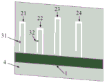
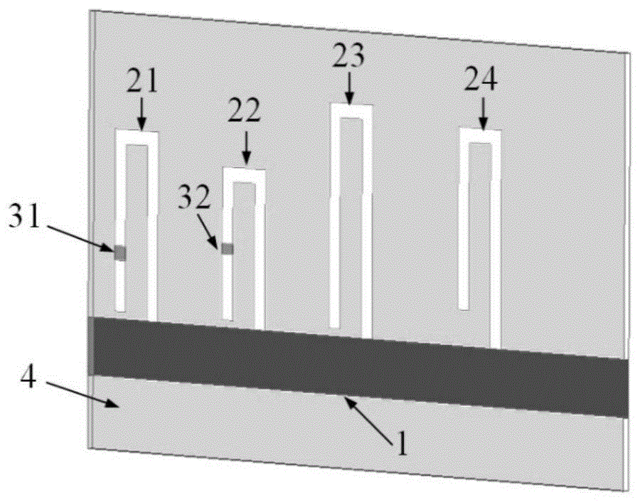
馈线(1)、编码单体(2)、弯折矩形微带贴片谐振结构(21,22,23,24)、开关(3)、弯折矩形微带贴片谐振结构(21)的开关(31)、弯折矩形微带贴片谐振结构(22)的开关(32)、介质基板(4)、下辐射面(5)Feeder (1), coding monomer (2), bent rectangular microstrip patch resonant structure (21, 22, 23, 24), switch (3), switch of the bent rectangular microstrip patch resonant structure (21) (31), the switch (32) of the bent rectangular microstrip patch resonant structure (22), the dielectric substrate (4), and the lower radiation surface (5)
具体实施方式Detailed ways
以下给出实施例,结合附图与具体仿真情况,对本发明技术方案做出进一步的说明。Embodiments are given below, and the technical solutions of the present invention are further described in conjunction with the accompanying drawings and specific simulation situations.
实施例Example
本实施例,矩形微带贴片RFID标签的可重构标签编码单体2如图1-图4的所示,仿真的介质基板材料选择RT5880高频板材料,10GHz IPC-TM 2.5.5.5标准下的相对介电常数εr,=2.20±0.02,损耗角正切tanδ=0.0014,标签编码的上辐射面由4个弯折矩形微带贴片谐振结构(21,22,23,24)与一条连接谐振结构和馈电的馈线(1)组成,它们与下辐射面(5)均选用铜箔片作为材料印刷到介质基板上。标签编码主要参数尺寸标注如图5,具体数据由下表1所示:In this embodiment, the reconfigurable
表1标签编码主要参数尺寸表Table 1 Label coding main parameter size table
本实施例的工作原理如下:The working principle of this embodiment is as follows:
由四个弯折矩形微带贴片谐振结构(21,22,23,24)构成主要编码结构,四个弯折矩形微带贴片谐振结构是滤波谐振器,总长度不同最终的谐振频率也不同,表征为一个4位标签编码,可以储存4位的信息量。当系统的阅读器天线发射出的射频询问信号流入标签编码的馈线时,经过不同长度的弯折矩形微带贴片谐振结构即会在相应的频点产生谐振。The main coding structure is composed of four bent rectangular microstrip patch resonant structures (21, 22, 23, 24). The four bent rectangular microstrip patch resonant structures are filter resonators, and the final resonant frequency is also different depending on the total length. Different, characterized by a 4-bit tag code, which can store 4-bit information. When the RF interrogation signal emitted by the reader antenna of the system flows into the feeder of the tag code, the resonant structure of the bent rectangular microstrip patch of different lengths will resonate at the corresponding frequency point.
其中弯折矩形微带贴片的谐振频率与总长度的关系有公式:The relationship between the resonant frequency of the bent rectangular microstrip patch and the total length has the formula:

其中等效介电常数是εe的介质基板,c为真空中的光速,在开关联通时的长度为b,如果开关断开则补偿长度为Δl,此时的谐振频率为fr。The equivalent dielectric constant is the dielectric substrate of ε e , c is the speed of light in vacuum, the length is b when the switch is on, the compensation length is Δl if the switch is off, and the resonant frequency at this time is fr .
标签的下辐射面(5)直接与被测对象即固体结构表面接触,全部印刷上铜箔片以保证上辐射面的编码结构不受贴面下的情况影响。The lower radiating surface (5) of the label is in direct contact with the measured object, that is, the surface of the solid structure, and all copper foils are printed to ensure that the coding structure of the upper radiating surface is not affected by the situation under the veneer.
标签编码一的开关(31,32)都设置在弯折点左边。The switches (31, 32) of
标签编码2的开关(31)设置在弯折点左边,开关(32)设置在弯折点右边。The switch (31) of the
仿真步骤Simulation steps
对于工作频段设定为1.50GHz至2.75GHz之间,这里方便讨论将其等分为五段(实际是否等分、分成几段可以灵活讨论):For the working frequency band set between 1.50GHz and 2.75GHz, it is convenient to discuss and divide it into five segments (whether it is actually divided into equal segments and divided into several segments can be discussed flexibly):
第一段(第一信息位):1.50GHz-1.75GHzThe first segment (first information bit): 1.50GHz-1.75GHz
第二段(第二信息位):1.75GHz-2.00GHzThe second segment (second information bit): 1.75GHz-2.00GHz
第三段(第三信息位):2.00GHz-2.25GHzThe third segment (third information bit): 2.00GHz-2.25GHz
第四段(第四信息位):2.25GHz-2.50GHzThe fourth segment (fourth information bit): 2.25GHz-2.50GHz
第五段(第五信息位):2.50GHz-2.75GHzFifth segment (fifth information bit): 2.50GHz-2.75GHz
对依据矩形微带贴片RFID标签标签编码的编码可重构方法设计的新型可重构标签编码进行仿真验证,在HFSS中选择RT5880高频板材(介电常数εr=2.29,损耗正切tanδ=0.0014)按照给出的尺寸制作模型,如图5所示。Simulation and verification of the new reconfigurable tag code based on the code reconfigurable method of rectangular microstrip patch RFID tag tag coding is carried out. In HFSS, RT5880 high-frequency plate (dielectric constant ε r =2.29, loss tangent tanδ = 0.0014) Make the model according to the given size, as shown in Figure 5.
在实例中为了对比添加一个不讨论可重构的含有四个编码单元的标签编码作为对照组,同时得到单个编码单元的电流密度如图6所示,颜色越深电流密度越大,颜色越浅电流密度越小。因此弯折点左边电流密度小,弯折点右边越靠近馈线连接处电流密度越大。In the example, a non-discussed reconfigurable tag code containing four coding units is added as a control group for comparison, and the current density of a single coding unit is obtained at the same time as shown in Figure 6. The darker the color, the higher the current density and the lighter the color. The lower the current density. Therefore, the current density on the left side of the bending point is small, and the closer the right side of the bending point is to the feeder connection, the higher the current density.
为了讨论二极管的通断,在标签编码一与标签编码二的弯折矩形微带贴片谐振结构(21)的弯折点左边设置Lumped RLC断口,在标签编码一的弯折矩形微带贴片谐振结构(22)的弯折点左边与标签编码二的弯折矩形微带贴片谐振结构(22)的弯折点右边设置Lumped RLC断口,参数设置为二极管断开时R=10MΩ,C=0.2pf,二极管导通时,R=0.5Ω,C=0。In order to discuss the on-off of the diode, a Lumped RLC fracture is set on the left side of the bending point of the bent rectangular microstrip patch resonant structure (21) of the
最终标签编码一与标签编码二得到的在开关断开时的S12参数图与对照组对比如图7、图8所示,其中分块阴影表示子频带,虚线划分出各编码单元的谐振频率偏移程度。由图可知:The S12 parameter map obtained when the switch is disconnected from the
对于标签编码一,两个二极管开关均在电流密度较小的弯折矩形微带贴片谐振结构弯折点左侧,当开关断开时,编码单元(21,22)的有效长度变短,依据谐振频率公式(1),谐振频率将升高,图中与对照组对比明显,编码单元(21,22)的谐振频率均有较大幅度的提高,谐振频率的间距也拉大了,其中编码单元(21)的谐振频率没有偏移出原先的子频带,因此这一子频带对应的信息位的编码信息仍然为“1”,而编码单元(22)的谐振频率偏移到了后一个子频带,则原先子频带对应的信息位的编码信息变成“0”,后一子频带对应的信息位编码信息变成“1”。而编码单元(23,24)由于电长度没有改变,谐振频率在其他编码单元的影响下仅发生极小的偏移,均未偏移出原子频带,携带的信息不变。For
测试结果:标签编码一携带的信息从“11110”经编码可重构变成了“11101”。Test result: The information carried by the tag encoding one changes from "11110" to "11101" after being encoded and reconstructed.
而对于标签编码二而言,谐振单元(21)的开关设置与标签编码一保持一致,而谐振单元(22)的开关设置位于电流密度较大的弯折矩形微带贴片谐振结构弯折点右侧,开关断开时,编码单元(21)由于有效电长度变短,谐振频率提高,但其谐振频率没有偏移出原先的子频带,因此这一子频带对应的信息位的编码信息仍然为“1”,编码单元(22)则由于电长度果断导致谐振频率过高,远超出该标签编码的测试范围,因此从工作频段范围消失,编码单元(23,24)受另外两个改变的编码单元的影响,在电长度不变的情况下谐振频率有小幅度的升高,均未偏移出原子频带,携带的信息不变。For the
测试结果:标签编码二携带的信息从“11110”经编码可重构变成了“11100”。Test result: The information carried by the
应用例Application example
应用在大型码头对集装箱的管理中,如图9所示,编码器附着于集装箱上,通过阅读器进行信号的发射与接收,传送回后台进行数据处理。It is used in the management of containers in large terminals. As shown in Figure 9, the encoder is attached to the container, and the signal is transmitted and received through the reader, and then sent back to the background for data processing.
对于该发明而言,可以适当分配标签实现多种信息的传输。不含二极管开关的标签是固定标签,可以用作为集装箱编码,每个集装箱可以对应一个独一无二的编码,而含有二极管开关的标签因为可以变动,能够灵活的传达多种信息。For this invention, it is possible to appropriately assign tags to realize the transmission of various information. Labels without diode switches are fixed labels and can be used as container codes. Each container can correspond to a unique code, while labels with diode switches can flexibly convey a variety of information because they can be changed.
结合本发明中的应用实例假设以下场景:In combination with the application examples in the present invention, the following scenarios are assumed:
集装箱编码(固定):Container code (fixed):
某个集装箱编号:“11”[对应于标签23,24,对应于第一与第二信息位]A certain container number: "11" [corresponding to
集装箱状态:Container Status:
1.集装箱有货物,第三信息位为“1”[对应于标签21]1. The container has cargo, the third information bit is "1" [corresponding to tag 21]
货物情况分类:Classification of goods:

2.集装箱内无货物,第三信息位为“0”[对应于标签21]2. There is no cargo in the container, the third information bit is "0" [corresponding to tag 21]
3.已经清空的集装箱中是否需要维修3. Whether maintenance is required in the emptied container

根据实际情况,标签、信息位的对应频带划分与编码位数都可以灵活改变以适应具体的应用。According to the actual situation, the corresponding frequency band division and coding number of tags and information bits can be flexibly changed to suit specific applications.
Claims (3)
Priority Applications (1)
| Application Number | Priority Date | Filing Date | Title |
|---|---|---|---|
| CN202010256498.3A CN111553051B (en) | 2020-04-02 | 2020-04-02 | A reconfigurable encoding method for rectangular microstrip patch RFID tags |
Applications Claiming Priority (1)
| Application Number | Priority Date | Filing Date | Title |
|---|---|---|---|
| CN202010256498.3A CN111553051B (en) | 2020-04-02 | 2020-04-02 | A reconfigurable encoding method for rectangular microstrip patch RFID tags |
Publications (2)
| Publication Number | Publication Date |
|---|---|
| CN111553051A true CN111553051A (en) | 2020-08-18 |
| CN111553051B CN111553051B (en) | 2024-03-19 |
Family
ID=71998239
Family Applications (1)
| Application Number | Title | Priority Date | Filing Date |
|---|---|---|---|
| CN202010256498.3A Active CN111553051B (en) | 2020-04-02 | 2020-04-02 | A reconfigurable encoding method for rectangular microstrip patch RFID tags |
Country Status (1)
| Country | Link |
|---|---|
| CN (1) | CN111553051B (en) |
Cited By (3)
| Publication number | Priority date | Publication date | Assignee | Title |
|---|---|---|---|---|
| CN112097963A (en) * | 2020-08-27 | 2020-12-18 | 西安电子科技大学 | A Stress Sensor Based on Chipless RFID Tag |
| CN115545138A (en) * | 2022-09-21 | 2022-12-30 | 重庆邮电大学 | Chipless RFID humidity sensing label of rectangular open ring |
| CN119443128A (en) * | 2024-10-29 | 2025-02-14 | 同济大学 | A radio frequency identification sensor controlled by a variable capacitance diode |
Citations (5)
| Publication number | Priority date | Publication date | Assignee | Title |
|---|---|---|---|---|
| US20020183013A1 (en) * | 2001-05-25 | 2002-12-05 | Auckland David T. | Programmable radio frequency sub-system with integrated antennas and filters and wireless communication device using same |
| US20080018475A1 (en) * | 2001-02-16 | 2008-01-24 | Automotive Technologies International, Inc. | Method and System for Obtaining Information about RFID-Equipped Objects |
| WO2008045151A1 (en) * | 2006-10-05 | 2008-04-17 | Pulse Finland Oy | Multi-band antenna with a common resonant feed structure and methods |
| KR101828219B1 (en) * | 2017-09-19 | 2018-02-12 | 한국지질자원연구원 | Tag for detecting a sink hole |
| WO2019143727A1 (en) * | 2018-01-17 | 2019-07-25 | Kymeta Corporation | Broad tunable bandwidth radial line slot antenna |
-
2020
- 2020-04-02 CN CN202010256498.3A patent/CN111553051B/en active Active
Patent Citations (5)
| Publication number | Priority date | Publication date | Assignee | Title |
|---|---|---|---|---|
| US20080018475A1 (en) * | 2001-02-16 | 2008-01-24 | Automotive Technologies International, Inc. | Method and System for Obtaining Information about RFID-Equipped Objects |
| US20020183013A1 (en) * | 2001-05-25 | 2002-12-05 | Auckland David T. | Programmable radio frequency sub-system with integrated antennas and filters and wireless communication device using same |
| WO2008045151A1 (en) * | 2006-10-05 | 2008-04-17 | Pulse Finland Oy | Multi-band antenna with a common resonant feed structure and methods |
| KR101828219B1 (en) * | 2017-09-19 | 2018-02-12 | 한국지질자원연구원 | Tag for detecting a sink hole |
| WO2019143727A1 (en) * | 2018-01-17 | 2019-07-25 | Kymeta Corporation | Broad tunable bandwidth radial line slot antenna |
Non-Patent Citations (4)
| Title |
|---|
| 代一平;李增权;: "基于RCS的交叉极化编码", 通信技术, no. 09 * |
| 孙海静;陈强;杨娇;周玲;: "基于混合编码的射频识别无芯片标签设计", 电子科技, no. 06 * |
| 王金魁;邹传云;胥磊;: "基于方向独立无芯RFID标签的频域编码研究", 电子技术应用, no. 05 * |
| 耿朋;杨曙辉;陈迎潮;: "基于超材料结构实现5.8GHz RFID天线小型化设计", 电子器件, no. 05 * |
Cited By (5)
| Publication number | Priority date | Publication date | Assignee | Title |
|---|---|---|---|---|
| CN112097963A (en) * | 2020-08-27 | 2020-12-18 | 西安电子科技大学 | A Stress Sensor Based on Chipless RFID Tag |
| CN112097963B (en) * | 2020-08-27 | 2021-10-08 | 西安电子科技大学 | A Stress Sensor Based on Chipless RFID Tag |
| CN115545138A (en) * | 2022-09-21 | 2022-12-30 | 重庆邮电大学 | Chipless RFID humidity sensing label of rectangular open ring |
| CN119443128A (en) * | 2024-10-29 | 2025-02-14 | 同济大学 | A radio frequency identification sensor controlled by a variable capacitance diode |
| CN119443128B (en) * | 2024-10-29 | 2025-11-07 | 同济大学 | Radio frequency identification sensor regulated by variable capacitance diode |
Also Published As
| Publication number | Publication date |
|---|---|
| CN111553051B (en) | 2024-03-19 |
Similar Documents
| Publication | Publication Date | Title |
|---|---|---|
| CN101378145B (en) | Tag antenna and tag | |
| US5182570A (en) | End fed flat antenna | |
| US7652637B2 (en) | Antenna, and radio-frequency identification tag | |
| CN111553051B (en) | A reconfigurable encoding method for rectangular microstrip patch RFID tags | |
| EP2525441A1 (en) | Miniaturized radio-frequency identification tag and microstrip patch antenna thereof | |
| CN101355195A (en) | UHF RFID Dual Band Anti-Metal Tag Antenna | |
| CN101777693A (en) | Ultrahigh frequency radio frequency identification anti-metal tag antenna with plane structure | |
| CN105305040A (en) | Antenna used for anti-metal tag and signal transmitting and receiving method of antenna | |
| CN103700931B (en) | A kind of small fractal crotch anti-metal tag antenna of loading opening resonant ring | |
| CN106785398A (en) | A kind of miniaturization hyperfrequency anti-metal paster antenna suitable on metal object | |
| KR100820544B1 (en) | RDF tag and its antenna | |
| CN202650044U (en) | A Chipless UHF RFID Tag Based on Multi-Resonant Dipole Antenna | |
| CN101901957A (en) | Micro radio frequency identification tag and micro strip patch antenna therein | |
| US8022815B2 (en) | Magnetic RFID coupler with balanced signal configuration | |
| CN106295775B (en) | A zigzag variable polarization chipless RFID tag and system | |
| CN108281773A (en) | A kind of customized circular polarisation anti-metal UHF RFID label antennas | |
| EP4478543A1 (en) | Antenna pattern and rfid inlay | |
| CN217641771U (en) | RFID reader antenna with degenerate mode separation unit | |
| KR20080070607A (en) | RFID tag antenna | |
| US7764240B2 (en) | Antenna configuration for RFID tags | |
| KR100860742B1 (en) | RFID tag antenna | |
| CN103280631A (en) | Planar inverted-F antenna (PIFA) for RFID (Radio Frequency Identification) special labels | |
| CN103401055B (en) | A kind of UHF anti-metal tag antenna of magnetic material substrate | |
| KR100867853B1 (en) | RFID antennas and RDF tags | |
| Sidén et al. | A distanced RFID dipole for a metallic supply chain label |
Legal Events
| Date | Code | Title | Description |
|---|---|---|---|
| PB01 | Publication | ||
| PB01 | Publication | ||
| SE01 | Entry into force of request for substantive examination | ||
| SE01 | Entry into force of request for substantive examination | ||
| GR01 | Patent grant | ||
| GR01 | Patent grant |