CN111545926B - Clamping device and method for laser cutting equipment - Google Patents
Clamping device and method for laser cutting equipment Download PDFInfo
- Publication number
- CN111545926B CN111545926B CN202010309033.XA CN202010309033A CN111545926B CN 111545926 B CN111545926 B CN 111545926B CN 202010309033 A CN202010309033 A CN 202010309033A CN 111545926 B CN111545926 B CN 111545926B
- Authority
- CN
- China
- Prior art keywords
- fixedly connected
- clamping
- cutting machine
- rotating
- shaped fixing
- Prior art date
- Legal status (The legal status is an assumption and is not a legal conclusion. Google has not performed a legal analysis and makes no representation as to the accuracy of the status listed.)
- Active
Links
- 238000003698 laser cutting Methods 0.000 title claims abstract description 41
- 238000000034 method Methods 0.000 title claims abstract description 13
- 238000005520 cutting process Methods 0.000 claims abstract description 48
- 230000008859 change Effects 0.000 claims description 8
- 230000005540 biological transmission Effects 0.000 claims description 5
- 230000008878 coupling Effects 0.000 claims description 2
- 238000010168 coupling process Methods 0.000 claims description 2
- 238000005859 coupling reaction Methods 0.000 claims description 2
- 230000000694 effects Effects 0.000 abstract description 8
- 239000002699 waste material Substances 0.000 abstract description 4
- 238000004519 manufacturing process Methods 0.000 description 2
- 230000006978 adaptation Effects 0.000 description 1
- 230000004075 alteration Effects 0.000 description 1
- 230000009286 beneficial effect Effects 0.000 description 1
- WABPQHHGFIMREM-UHFFFAOYSA-N lead(0) Chemical compound [Pb] WABPQHHGFIMREM-UHFFFAOYSA-N 0.000 description 1
- 230000005012 migration Effects 0.000 description 1
- 238000013508 migration Methods 0.000 description 1
- 238000012986 modification Methods 0.000 description 1
- 230000004048 modification Effects 0.000 description 1
- 230000003287 optical effect Effects 0.000 description 1
- 230000003068 static effect Effects 0.000 description 1
- 238000006467 substitution reaction Methods 0.000 description 1
Images


Classifications
-
- B—PERFORMING OPERATIONS; TRANSPORTING
- B23—MACHINE TOOLS; METAL-WORKING NOT OTHERWISE PROVIDED FOR
- B23K—SOLDERING OR UNSOLDERING; WELDING; CLADDING OR PLATING BY SOLDERING OR WELDING; CUTTING BY APPLYING HEAT LOCALLY, e.g. FLAME CUTTING; WORKING BY LASER BEAM
- B23K26/00—Working by laser beam, e.g. welding, cutting or boring
- B23K26/36—Removing material
- B23K26/38—Removing material by boring or cutting
-
- B—PERFORMING OPERATIONS; TRANSPORTING
- B23—MACHINE TOOLS; METAL-WORKING NOT OTHERWISE PROVIDED FOR
- B23K—SOLDERING OR UNSOLDERING; WELDING; CLADDING OR PLATING BY SOLDERING OR WELDING; CUTTING BY APPLYING HEAT LOCALLY, e.g. FLAME CUTTING; WORKING BY LASER BEAM
- B23K26/00—Working by laser beam, e.g. welding, cutting or boring
- B23K26/08—Devices involving relative movement between laser beam and workpiece
- B23K26/0823—Devices involving rotation of the workpiece
-
- B—PERFORMING OPERATIONS; TRANSPORTING
- B23—MACHINE TOOLS; METAL-WORKING NOT OTHERWISE PROVIDED FOR
- B23K—SOLDERING OR UNSOLDERING; WELDING; CLADDING OR PLATING BY SOLDERING OR WELDING; CUTTING BY APPLYING HEAT LOCALLY, e.g. FLAME CUTTING; WORKING BY LASER BEAM
- B23K26/00—Working by laser beam, e.g. welding, cutting or boring
- B23K26/08—Devices involving relative movement between laser beam and workpiece
- B23K26/0869—Devices involving movement of the laser head in at least one axial direction
- B23K26/0876—Devices involving movement of the laser head in at least one axial direction in at least two axial directions
-
- B—PERFORMING OPERATIONS; TRANSPORTING
- B23—MACHINE TOOLS; METAL-WORKING NOT OTHERWISE PROVIDED FOR
- B23K—SOLDERING OR UNSOLDERING; WELDING; CLADDING OR PLATING BY SOLDERING OR WELDING; CUTTING BY APPLYING HEAT LOCALLY, e.g. FLAME CUTTING; WORKING BY LASER BEAM
- B23K26/00—Working by laser beam, e.g. welding, cutting or boring
- B23K26/70—Auxiliary operations or equipment
- B23K26/702—Auxiliary equipment
-
- B—PERFORMING OPERATIONS; TRANSPORTING
- B23—MACHINE TOOLS; METAL-WORKING NOT OTHERWISE PROVIDED FOR
- B23K—SOLDERING OR UNSOLDERING; WELDING; CLADDING OR PLATING BY SOLDERING OR WELDING; CUTTING BY APPLYING HEAT LOCALLY, e.g. FLAME CUTTING; WORKING BY LASER BEAM
- B23K37/00—Auxiliary devices or processes, not specially adapted for a procedure covered by only one of the other main groups of this subclass
- B23K37/04—Auxiliary devices or processes, not specially adapted for a procedure covered by only one of the other main groups of this subclass for holding or positioning work
- B23K37/0426—Fixtures for other work
- B23K37/0435—Clamps
Landscapes
- Engineering & Computer Science (AREA)
- Physics & Mathematics (AREA)
- Optics & Photonics (AREA)
- Mechanical Engineering (AREA)
- Plasma & Fusion (AREA)
- Laser Beam Processing (AREA)
Abstract
The invention discloses a clamping device for laser cutting equipment, which comprises a fixed base, wherein the upper surface of the fixed base is fixedly connected with a cutting case, the side surface of the cutting case is provided with a rotating motor, the inner bottom wall of the cutting case is provided with a controller, and the inner side wall of the cutting case is provided with a speed changing case; the invention also provides a use method of the clamping device for the laser cutting equipment, which comprises the following steps: s1, the telescopic rod is controlled to enable the two first movable blocks and the two second movable blocks to expand and move through the cross-shaped clamping grooves, and the two first V-shaped fixing frames and the two second V-shaped fixing frames drive the two first clamping rods and the two second clamping rods to move. According to the clamping device for the collecting ring and the laser cutting equipment, the telescopic rod is arranged to lift the first movable block, the second movable block, the first V-shaped fixing frame, the second V-shaped fixing frame, the first clamping rod and the second clamping rod, so that the cut object can be clamped between the four clamping rods, the effect of firmly clamping the cut object can be achieved, and the generation of cutting waste products is reduced.
Description
Technical Field
The invention relates to the technical field of laser cutting machinery, in particular to a clamping device and a clamping method for laser cutting equipment.
Background
The collecting ring is also called conducting ring, slip ring, collecting ring, etc. it can be used in the electromechanical system which requires continuous rotation and needs to be communicated and transmitted from fixed position to rotating position, the collecting ring is generally used in the motor, the electric energy of the coil rotating by the motor rotor is respectively connected to the conducting wire of the collecting ring from one end by the lead wire, the conducting wire respectively transmits the electric energy to the slip ring of the collecting ring, when the slip ring rotates, no matter the slip ring rotates, the electric energy is always transmitted by the contact of the outer circle of the slip ring and the static electric brush, the cutting is needed in the processing course of the collecting ring, generally the laser cutting is used.
Laser cutting is to follow the laser that the laser instrument launches, through optical path system, focuses on the laser beam of high power density, need use clamping device to grasp collecting ring before carrying out laser cutting, and current clamping device can only be usually from both sides treat the cutting piece centre gripping, and the clamping effect is not good, and is unstable inadequately, produces the waste product easily.
Thus. We provide a clamping device and method for a laser cutting apparatus.
Disclosure of Invention
The present invention is directed to a clamping device and a method for a laser cutting apparatus, so as to solve the problems of the background art.
In order to achieve the purpose, the invention provides the following technical scheme: a clamping device and a method for laser cutting equipment comprise a fixed base, wherein the upper surface of the fixed base is fixedly connected with a cutting machine box, the side surface of the cutting machine box is provided with a rotating motor, the inner bottom wall of the cutting machine box is provided with a controller, the inner side wall of the cutting machine box is provided with a speed changing machine box, the side surface of the speed changing machine box is provided with a rotating shaft, the side surface of the cutting machine box is fixedly connected with a fixed disc, the side surface of the fixed disc is fixedly connected with an air pressure disc, the side surface of the air pressure disc is fixedly connected with a fixed block, the side surface of the fixed block is fixedly connected with a rotary disc sleeve, the side surface of the rotary disc sleeve is provided with a pneumatic universal joint, the side surface of the rotary disc sleeve is provided with a rotary chuck, the inside of the rotary chuck is provided with a shaft sleeve, the surface of the shaft sleeve is provided with a rotating shaft, the inner bottom wall of the rotary chuck is provided with a telescopic rod, the front of rotating chuck is provided with first movable block, the first V type mount of side fixedly connected with of first movable block, the first clamping rod of top fixedly connected with of first V type mount, the side of rotating chuck is provided with the second movable block, the side fixedly connected with second V type mount of second movable block, the top fixedly connected with second clamping rod of second V type mount, cross draw-in groove has been seted up to the side of rotating chuck, the side of rotating chuck is provided with the collecting ring.
Preferably, the last fixed surface of cutting machine case is connected with the laser tool bit case, the lower fixed surface of laser tool bit case is connected with horizontal sharp slip table, the lower surface of horizontal sharp slip table is provided with vertical sharp slip table, the lower fixed surface of vertical sharp slip table is connected with laser cutting machine, laser cutting machine's lower surface is provided with the cutting head, horizontal sharp slip table, vertical sharp slip table and laser cutting machine all with controller coupling connection.
Preferably, the front of the cutting case is provided with a control panel, the side of the cutting case is provided with a through hole matched with the output shaft of the rotating motor, the output shaft of the rotating motor passes through the through hole and extends into the transmission case, and the rotating shaft is in transmission connection with the transmission case.
Preferably, the side of fixed disk, air pressure dish and carousel cover all seted up with the through-hole of axis of rotation adaptation, the axis of rotation passes through the through-hole and extends to the side and the axle sleeve fixed connection of carousel cover.
Preferably, the number of the pneumatic universal joints is two, through holes matched with the pneumatic universal joints are formed in the side face of the rotary plate sleeve, and the two pneumatic universal joints are fixedly connected with the telescopic rod through the through holes.
Preferably, the quantity of telescopic link is four, four the telescopic link all sets up in the inside of rotating chuck, and the telescopic link is pneumatic telescoping rod.
Preferably, the number of the first movable blocks is two, two the first movable blocks are respectively and fixedly connected to the top ends of the telescopic rods on the two opposite surfaces, the number of the first V-shaped fixing frames is two, and the first V-shaped fixing frames are respectively and fixedly connected to the side surfaces of the two first movable blocks.
Preferably, the number of the second movable blocks is two, two the second movable blocks are respectively and fixedly connected to the top ends of the telescopic rods on the two opposite surfaces, the number of the second V-shaped fixing frames is two, and the second V-shaped fixing frames are respectively and fixedly connected to the side surfaces of the two second movable blocks.
Preferably, the number of the first clamping rods and the second clamping rods is two, and the first clamping rods and the second clamping rods are fixedly connected to the top ends of the two first V-shaped fixing frames and the top ends of the two second V-shaped fixing frames.
The invention also provides a use method of the clamping device for the laser cutting equipment, which comprises the following steps:
s1, firstly, the telescopic rod is controlled to enable the two first movable blocks and the two second movable blocks to expand and move through the cross-shaped clamping grooves, and the two first V-shaped fixed frames and the two second V-shaped fixed frames drive the two first clamping rods and the two second clamping rods to move;
s2, placing the collecting ring in the middle of the rotating chuck, and starting the four telescopic rods to enable the two first clamping rods and the two second clamping rods to clamp the collecting ring from four directions;
and S3, starting the rotating motor and the laser cutting machine to cut.
Advantageous effects
The invention provides a clamping device and a method for laser cutting equipment, which have the following beneficial effects:
1. this clamping device for collecting ring and laser cutting equipment, through setting up atmospheric pressure dish and pneumatic universal joint, can provide atmospheric pressure for the telescopic link, through setting up first movable block and second movable block, be convenient for first V type mount and second V type mount can remove, through setting up first clamping bar and second clamping bar, can carry out the centre gripping in four faces by the cutting article, be convenient for can be tightly pressed from both sides between four clamping bars by the cutting article, thereby reach the effect that can firmly press from both sides tight article, the production of cutting waste product has been reduced.
2. This clamping device for collecting ring and laser cutting equipment rotates the motor through setting up, is convenient for make and rotates the chuck and can rotate, drives and is rotated by the thing, through setting up horizontal sharp slip table and vertical sharp slip table, can make laser cutting machine horizontal and vertical horizontal migration, through setting up the cutting head, is convenient for cut tight article to when reaching cutting article, can diversely carry out the effect of cutting.
Drawings
FIG. 1 is a schematic front sectional view of the present invention;
FIG. 2 is an enlarged schematic view of the structure at A in FIG. 1;
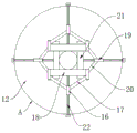
fig. 3 is a side view of the spin chuck.
In the figure: 1 unable adjustment base, 2 cutting machine casees, 3 rotate the motor, 4 controllers, 5 gear boxes, 6 axis of rotation, 7 fixed disks, 8 pneumatic disks, 9 fixed blocks, 10 carousel cover, 11 pneumatic universal joints, 12 rotating chuck, 13 axle sleeves, 14 pivots, 15 telescopic links, 16 first movable blocks, 17 first V type mount, 18 first clamp rod, 19 second movable blocks, 20 second V type mount, 21 second clamp rod, 22 cross draw-in grooves, 23 collecting rings, 24 laser tool bit casees, 25 horizontal straight line slip tables, 26 vertical straight line slip tables, 27 laser cutting machine, 28 cutting heads.
Detailed Description
The technical solutions in the embodiments of the present invention will be clearly and completely described below with reference to the drawings in the embodiments of the present invention, and it is obvious that the described embodiments are only a part of the embodiments of the present invention, and not all of the embodiments. All other embodiments, which can be derived by a person skilled in the art from the embodiments given herein without making any creative effort, shall fall within the protection scope of the present invention.
Referring to fig. 1-3, the present invention provides a technical solution: a clamping device and a method for laser cutting equipment comprise a fixed base 1, wherein the upper surface of the fixed base 1 is fixedly connected with a cutting machine case 2, the front surface of the cutting machine case 2 is provided with a control panel, the side surface of the cutting machine case 2 is provided with a through hole matched with the output shaft of a rotating motor 3, the output shaft of the rotating motor 3 passes through the through hole and extends into the interior of a speed change machine case 5, a rotating shaft 6 is in transmission connection with the speed change machine case 5, the rotating chuck 12 can rotate by arranging the rotating motor 3 to drive a cut object to rotate, the side surface of the cutting machine case 2 is provided with the rotating motor 3, the inner bottom wall of the cutting machine case 2 is provided with a controller 4, the inner side wall of the cutting machine case 2 is provided with the speed change machine case 5, the side surface of the speed change machine case 5 is provided with the rotating shaft 6, the side surface of the cutting machine case 2 is fixedly connected with a fixed disc 7, and the side surface of the fixed disc 7 is fixedly connected with an air pressure disc 8, the side surfaces of the fixed disc 7, the air pressure disc 8 and the rotary disc sleeve 10 are all provided with through holes matched with the rotating shaft 6, the rotating shaft 6 passes through the through holes and extends to the side surface of the rotary disc sleeve 10 to be fixedly connected with a shaft sleeve 13, the side surface of the air pressure disc 8 is fixedly connected with a fixed block 9, the side surface of the fixed block 9 is fixedly connected with the rotary disc sleeve 10, the side surface of the rotary disc sleeve 10 is provided with two pneumatic universal joints 11, the side surface of the rotary disc sleeve 10 is provided with through holes matched with the pneumatic universal joints 11, the two pneumatic universal joints 11 are fixedly connected with telescopic rods 15 through the through holes, the side surface of the rotary disc sleeve 10 is provided with a rotary chuck 12, the inside of the rotary chuck 12 is provided with the shaft sleeve 13, the surface of the shaft sleeve 13 is provided with a rotating shaft 14, the inner bottom wall of the rotary chuck 12 is provided with the telescopic rods 15, the number of the telescopic rods 15 is four, and the four telescopic rods 15 are all arranged inside the rotary chuck 12, the telescopic rod 15 is an air pressure telescopic rod, the front surface of the rotating chuck 12 is provided with a first movable block 16, the number of the first movable blocks 16 is two, the two first movable blocks 16 are respectively and fixedly connected with the top ends of the telescopic rods 15 at two opposite surfaces, the side surface of the first movable block 16 is fixedly connected with a first V-shaped fixed frame 17, the number of the first V-shaped fixed frames 17 is two, the two first V-shaped fixed frames 17 are respectively and fixedly connected with the side surfaces of the two first movable blocks 16, the top end of the first V-shaped fixed frame 17 is fixedly connected with a first clamping rod 18, the number of the first clamping rod 18 and the number of the second clamping rod 21 are both two, the two first clamping rods 18 and the two second clamping rods 21 are respectively and fixedly connected with the top ends of the two first V-shaped fixed frames 17 and the two second V-shaped fixed frames 20, the side surface of the rotating chuck 12 is provided with a second movable block 19, and the number of the second movable block 19 is two, two second movable blocks 19 are respectively and fixedly connected with the top ends of the two opposite telescopic rods 15, the side surfaces of the second movable blocks 19 are fixedly connected with two V-shaped fixed frames 20, the number of the second V-shaped fixed frames 20 is two, the two second V-shaped fixed frames 20 are respectively and fixedly connected with the side surfaces of the two second movable blocks 19, the top end of the second V-shaped fixed frame 20 is fixedly connected with a second clamping rod 21, the side surface of the rotating chuck 12 is provided with a cross-shaped clamping groove 22, the side surface of the rotating chuck 12 is provided with a collecting ring 23, the upper surface of the cutting machine case 2 is fixedly connected with a laser tool bit case 24, the lower surface of the laser tool bit case 24 is fixedly connected with a transverse linear sliding table 25, the lower surface of the transverse linear sliding table 25 is provided with a vertical linear sliding table 26, and the laser cutting machine 27 can horizontally and vertically move by arranging the transverse linear sliding table 25 and the vertical linear sliding table 26, the lower surface fixedly connected with laser cutting machine 27 of vertical straight line slip table 26, laser cutting machine 27's lower surface is provided with cutting head 28, through setting up cutting head 28, is convenient for cut the article that is pressed from both sides tightly to when reaching cutting article, can diversified cutting effect. The transverse linear sliding table 25, the vertical linear sliding table 26 and the laser cutting machine 27 are all coupled with the controller 4.
Through setting up pneumatic disk 8 and pneumatic universal joint 11, can provide atmospheric pressure for telescopic link 15, through setting up first movable block 16 and second movable block 19, be convenient for first V type mount 17 and second V type mount 20 can remove, through setting up first clamp lever 18 and second clamp lever 21, can carry out the centre gripping in four faces by the thing piece of being cut, be convenient for by the cutting thing can be pressed from both sides tightly between four clamp levers, thereby reach the effect that can firmly press from both sides the thing, the production of cutting waste product has been reduced.
The invention also provides a use method of the clamping device for the laser cutting equipment, which comprises the following steps:
s1, firstly, the telescopic rod 15 is controlled to enable the two first movable blocks 16 and the two second movable blocks 19 to expand and move through the cross-shaped clamping grooves 22, and the two first V-shaped fixed frames 17 and the two second V-shaped fixed frames 20 drive the two first clamping rods 18 and the two second clamping rods 21 to move;
s2, the collecting ring 23 is placed in the middle of the rotating chuck 12, and the four telescopic rods 15 are started to enable the two first clamping rods 18 and the two second clamping rods 21 to clamp the collecting ring 23 from four directions;
and S3, starting the rotating motor 3 and the laser cutting machine 27 to cut.
The working principle is as follows: when the clamping device for the collecting ring and the laser cutting equipment is used, firstly, the telescopic rod 15 is controlled to enable the two first movable blocks 16 and the two second movable blocks 19 to expand and move through the cross-shaped clamping groove 22, the two first V-shaped fixing frames 17 and the two second V-shaped fixing frames 20 drive the two first clamping rods 18 and the two second clamping rods 21 to move, the collecting ring 23 is placed in the middle of the rotating chuck 12, the four telescopic rods 15 are started to enable the two first clamping rods 18 and the two second clamping rods 21 to clamp the collecting ring 23 from four directions, and then the rotating motor 3 and the laser cutting machine 27 are started to cut the collecting ring, so that the effect of firmly clamping a cut object and performing laser cutting is achieved.
Although embodiments of the present invention have been shown and described, it will be appreciated by those skilled in the art that changes, modifications, substitutions and alterations can be made in these embodiments without departing from the principles and spirit of the invention, the scope of which is defined in the appended claims and their equivalents.
Claims (4)
1. The utility model provides a clamping device for laser cutting equipment, includes unable adjustment base (1), its characterized in that: the cutting machine is characterized in that a cutting machine box (2) is fixedly connected to the upper surface of a fixed base (1), a rotating motor (3) is arranged on the side surface of the cutting machine box (2), a controller (4) is arranged on the inner bottom wall of the cutting machine box (2), a speed change machine box (5) is arranged on the inner side wall of the cutting machine box (2), a rotating shaft (6) is arranged on the side surface of the speed change machine box (5), a fixed disc (7) is fixedly connected to the side surface of the cutting machine box (2), an air pressure disc (8) is fixedly connected to the side surface of the fixed disc (7), a fixed block (9) is fixedly connected to the side surface of the air pressure disc (8), a rotating disc sleeve (10) is fixedly connected to the side surface of the fixed block (9), a pneumatic universal joint (11) is arranged on the side surface of the rotating disc sleeve (10), a rotating chuck (12) is arranged on the side surface of the rotating disc sleeve (10), and a shaft sleeve (13) is arranged in the rotating chuck (12), the surface of the shaft sleeve (13) is provided with a rotating shaft (14), the inner bottom wall of the rotating chuck (12) is provided with a telescopic rod (15), the front face of the rotating chuck (12) is provided with a first movable block (16), the side face of the first movable block (16) is fixedly connected with a first V-shaped fixing frame (17), the top end of the first V-shaped fixing frame (17) is fixedly connected with a first clamping rod (18), the side face of the rotating chuck (12) is provided with a second movable block (19), the side face of the second movable block (19) is fixedly connected with a second V-shaped fixing frame (20), the top end of the second V-shaped fixing frame (20) is fixedly connected with a second clamping rod (21), the side face of the rotating chuck (12) is provided with a cross-shaped clamping groove (22), and the side face of the rotating chuck (12) is provided with a collecting ring (23);
the side surfaces of the fixed disc (7), the air pressure disc (8) and the rotary disc sleeve (10) are all provided with through holes matched with the rotating shaft (6), and the rotating shaft (6) passes through the through holes and extends to the side surface of the rotary disc sleeve (10) to be fixedly connected with the shaft sleeve (13);
the number of the pneumatic universal joints (11) is two, through holes matched with the pneumatic universal joints (11) are formed in the side face of the turntable sleeve (10), and the two pneumatic universal joints (11) are fixedly connected with the telescopic rod (15) through the through holes;
the number of the telescopic rods (15) is four, the four telescopic rods (15) are all arranged in the rotating chuck (12), and the telescopic rods (15) are air pressure telescopic rods;
the number of the first movable blocks (16) is two, the two first movable blocks (16) are respectively and fixedly connected to the top ends of the telescopic rods (15) on the two opposite surfaces, the number of the first V-shaped fixed frames (17) is two, and the two first V-shaped fixed frames (17) are respectively and fixedly connected to the side surfaces of the two first movable blocks (16);
the number of the second movable blocks (19) is two, the two second movable blocks (19) are respectively and fixedly connected to the top ends of the telescopic rods (15) on the two opposite surfaces, the number of the second V-shaped fixing frames (20) is two, and the two second V-shaped fixing frames (20) are respectively and fixedly connected to the side surfaces of the two second movable blocks (19);
the number of the first clamping rods (18) and the second clamping rods (21) is two, and the first clamping rods (18) and the second clamping rods (21) are fixedly connected to the top ends of the two first V-shaped fixing frames (17) and the top ends of the two second V-shaped fixing frames (20).
2. The clamping device for the laser cutting equipment as set forth in claim 1, wherein: the last fixed surface of cutting machine case (2) is connected with laser tool bit case (24), the horizontal sharp slip table of lower fixed surface (25) of laser tool bit case (24) is connected with, the lower surface of horizontal sharp slip table (25) is provided with vertical sharp slip table (26), the lower fixed surface of vertical sharp slip table (26) is connected with laser cutting machine (27), the lower surface of laser cutting machine (27) is provided with cutting head (28), horizontal sharp slip table (25), vertical sharp slip table (26) and laser cutting machine (27) all with controller (4) coupling connection.
3. The clamping device for the laser cutting equipment as set forth in claim 2, wherein: the front of the cutting machine case (2) is provided with a control panel, a through hole matched with an output shaft of the rotating motor (3) is formed in the side face of the cutting machine case (2), the output shaft of the rotating motor (3) passes through the through hole and extends to the inside of the speed change case (5), and the rotating shaft (6) is in transmission connection with the speed change case (5).
4. The use method of the clamping device for the laser cutting equipment as claimed in claim 3, characterized in that: the method comprises the following steps:
s1, firstly, controlling the telescopic rod (15) to enable the two first movable blocks (16) and the two second movable blocks (19) to expand and move through the cross-shaped clamping grooves (22), and enabling the two first V-shaped fixing frames (17) and the two second V-shaped fixing frames (20) to drive the two first clamping rods (18) and the two second clamping rods (21) to move;
s2, placing the collecting ring (23) in the middle of the rotating chuck (12), and starting the four telescopic rods (15) to enable the two first clamping rods (18) and the two second clamping rods (21) to clamp the collecting ring (23) from four directions;
s3, and then starting the rotating motor (3) and the laser cutting machine (27) to cut.
Priority Applications (1)
| Application Number | Priority Date | Filing Date | Title |
|---|---|---|---|
| CN202010309033.XA CN111545926B (en) | 2020-04-19 | 2020-04-19 | Clamping device and method for laser cutting equipment |
Applications Claiming Priority (1)
| Application Number | Priority Date | Filing Date | Title |
|---|---|---|---|
| CN202010309033.XA CN111545926B (en) | 2020-04-19 | 2020-04-19 | Clamping device and method for laser cutting equipment |
Publications (2)
| Publication Number | Publication Date |
|---|---|
| CN111545926A CN111545926A (en) | 2020-08-18 |
| CN111545926B true CN111545926B (en) | 2021-12-21 |
Family
ID=72003844
Family Applications (1)
| Application Number | Title | Priority Date | Filing Date |
|---|---|---|---|
| CN202010309033.XA Active CN111545926B (en) | 2020-04-19 | 2020-04-19 | Clamping device and method for laser cutting equipment |
Country Status (1)
| Country | Link |
|---|---|
| CN (1) | CN111545926B (en) |
Families Citing this family (1)
| Publication number | Priority date | Publication date | Assignee | Title |
|---|---|---|---|---|
| CN114346481B (en) * | 2022-03-17 | 2022-05-31 | 深圳水滴激光科技有限公司 | A spare part cutting device for laser cleaning machine |
Family Cites Families (6)
| Publication number | Priority date | Publication date | Assignee | Title |
|---|---|---|---|---|
| DE2425349A1 (en) * | 1974-05-25 | 1975-12-04 | Messer Griesheim Gmbh | PIPE CUTTING AND / OR WELDING MACHINE |
| CN203944996U (en) * | 2014-06-26 | 2014-11-19 | 武汉天琪激光设备制造有限公司 | A kind of laser pipe cutter |
| CN206047367U (en) * | 2016-08-23 | 2017-03-29 | 东莞市飞越激光设备有限公司 | A laser cutting machine for high-precision machining of long round tubes |
| CN108213479A (en) * | 2018-03-20 | 2018-06-29 | 武汉冠油科技有限公司 | A kind of four paws automatic centering air spider |
| CN209094786U (en) * | 2018-07-16 | 2019-07-12 | 徐州亚鸿数控设备制造厂 | A kind of numerical control tube sheet all-in-one machine |
| CN209867706U (en) * | 2019-02-28 | 2019-12-31 | 常州优特卡机械有限公司 | Be used for dedicated pneumatic double acting full stroke chuck of laser pipe cutting |
-
2020
- 2020-04-19 CN CN202010309033.XA patent/CN111545926B/en active Active
Also Published As
| Publication number | Publication date |
|---|---|
| CN111545926A (en) | 2020-08-18 |
Similar Documents
| Publication | Publication Date | Title |
|---|---|---|
| CN111545926B (en) | Clamping device and method for laser cutting equipment | |
| CN105522860A (en) | Four-shaft character carving machine for tire molds and character carving method thereof | |
| CN213615440U (en) | Double-sided milling machine device for surface processing of speed reducer body | |
| CN109551119A (en) | A kind of dimension laser cutting intelligent robot | |
| CN112731591A (en) | Optical fiber stripping, cleaning and cutting integrated machine and optical fiber stripping, cleaning and cutting method | |
| CN214151125U (en) | Optical fiber stripping, cleaning and cutting integrated machine | |
| CN209999493U (en) | stone profiling abrasive cutting machine | |
| CN104338968B (en) | Multifunctional processing equipment for products | |
| CN220093282U (en) | Clamping tool for gear shaping machine | |
| CN215747698U (en) | High efficiency cutting and punching equipment of pipe fitting production and processing | |
| CN113199050B (en) | Recyclable model machining system | |
| CN214685384U (en) | Be applied to apron processing tool of peritoneal dialysis machine | |
| CN214603032U (en) | Quick-change tool machining equipment for repairing cast parts | |
| CN213003708U (en) | Automatic bore hinge pinhole device | |
| CN213411187U (en) | Novel perforating machine | |
| CN212577632U (en) | Spare part cutting equipment convenient to use | |
| CN204621570U (en) | A kind of self-centering type centre frame | |
| CN203900647U (en) | Multi-shaft tapping machine | |
| CN210360535U (en) | Waste cleaning device for radial drilling machine | |
| CN210755785U (en) | Locking rod hole cutting machine | |
| CN216451268U (en) | Stator glue filling device for motor production | |
| CN206317190U (en) | A kind of tenon process equipment | |
| CN210818387U (en) | Combined machining workbench | |
| CN211991814U (en) | Nine-axis linkage machining center is with processing work piece drive arrangement | |
| CN219666472U (en) | Automobile part horizontal assembly angle adjusting device |
Legal Events
| Date | Code | Title | Description |
|---|---|---|---|
| PB01 | Publication | ||
| PB01 | Publication | ||
| SE01 | Entry into force of request for substantive examination | ||
| SE01 | Entry into force of request for substantive examination | ||
| TA01 | Transfer of patent application right | ||
| TA01 | Transfer of patent application right |
Effective date of registration: 20211201 Address after: 756000 small and medium-sized enterprise science and technology entrepreneurship Park, Jianye street, Guyuan Economic Development Zone, Ningxia Hui Autonomous Region Applicant after: Guyuan Ningnan Sifang Technology Co.,Ltd. Address before: 550025 Guizhou University, 2708 south section of Huaxi Avenue, Huaxi District, Guiyang City, Guizhou Province Applicant before: Niu Jiankang |
|
| GR01 | Patent grant | ||
| GR01 | Patent grant |