CN111542501B - Method for the biological processing of hydrocarbonaceous materials and system for carrying out the method - Google Patents
Method for the biological processing of hydrocarbonaceous materials and system for carrying out the method Download PDFInfo
- Publication number
- CN111542501B CN111542501B CN201880069908.4A CN201880069908A CN111542501B CN 111542501 B CN111542501 B CN 111542501B CN 201880069908 A CN201880069908 A CN 201880069908A CN 111542501 B CN111542501 B CN 111542501B
- Authority
- CN
- China
- Prior art keywords
- tank
- coal slurry
- water
- creosote
- combustion gas
- Prior art date
- Legal status (The legal status is an assumption and is not a legal conclusion. Google has not performed a legal analysis and makes no representation as to the accuracy of the status listed.)
- Active
Links
Images


Classifications
-
- C—CHEMISTRY; METALLURGY
- C10—PETROLEUM, GAS OR COKE INDUSTRIES; TECHNICAL GASES CONTAINING CARBON MONOXIDE; FUELS; LUBRICANTS; PEAT
- C10G—CRACKING HYDROCARBON OILS; PRODUCTION OF LIQUID HYDROCARBON MIXTURES, e.g. BY DESTRUCTIVE HYDROGENATION, OLIGOMERISATION, POLYMERISATION; RECOVERY OF HYDROCARBON OILS FROM OIL-SHALE, OIL-SAND, OR GASES; REFINING MIXTURES MAINLY CONSISTING OF HYDROCARBONS; REFORMING OF NAPHTHA; MINERAL WAXES
- C10G1/00—Production of liquid hydrocarbon mixtures from oil-shale, oil-sand, or non-melting solid carbonaceous or similar materials, e.g. wood, coal
- C10G1/02—Production of liquid hydrocarbon mixtures from oil-shale, oil-sand, or non-melting solid carbonaceous or similar materials, e.g. wood, coal by distillation
-
- B—PERFORMING OPERATIONS; TRANSPORTING
- B01—PHYSICAL OR CHEMICAL PROCESSES OR APPARATUS IN GENERAL
- B01D—SEPARATION
- B01D53/00—Separation of gases or vapours; Recovering vapours of volatile solvents from gases; Chemical or biological purification of waste gases, e.g. engine exhaust gases, smoke, fumes, flue gases, aerosols
- B01D53/14—Separation of gases or vapours; Recovering vapours of volatile solvents from gases; Chemical or biological purification of waste gases, e.g. engine exhaust gases, smoke, fumes, flue gases, aerosols by absorption
- B01D53/1418—Recovery of products
-
- B—PERFORMING OPERATIONS; TRANSPORTING
- B01—PHYSICAL OR CHEMICAL PROCESSES OR APPARATUS IN GENERAL
- B01D—SEPARATION
- B01D5/00—Condensation of vapours; Recovering volatile solvents by condensation
- B01D5/0033—Other features
- B01D5/0036—Multiple-effect condensation; Fractional condensation
-
- B—PERFORMING OPERATIONS; TRANSPORTING
- B01—PHYSICAL OR CHEMICAL PROCESSES OR APPARATUS IN GENERAL
- B01D—SEPARATION
- B01D5/00—Condensation of vapours; Recovering volatile solvents by condensation
- B01D5/0078—Condensation of vapours; Recovering volatile solvents by condensation characterised by auxiliary systems or arrangements
- B01D5/009—Collecting, removing and/or treatment of the condensate
-
- B—PERFORMING OPERATIONS; TRANSPORTING
- B01—PHYSICAL OR CHEMICAL PROCESSES OR APPARATUS IN GENERAL
- B01D—SEPARATION
- B01D5/00—Condensation of vapours; Recovering volatile solvents by condensation
- B01D5/0078—Condensation of vapours; Recovering volatile solvents by condensation characterised by auxiliary systems or arrangements
- B01D5/0093—Removing and treatment of non condensable gases
-
- B—PERFORMING OPERATIONS; TRANSPORTING
- B01—PHYSICAL OR CHEMICAL PROCESSES OR APPARATUS IN GENERAL
- B01D—SEPARATION
- B01D53/00—Separation of gases or vapours; Recovering vapours of volatile solvents from gases; Chemical or biological purification of waste gases, e.g. engine exhaust gases, smoke, fumes, flue gases, aerosols
- B01D53/14—Separation of gases or vapours; Recovering vapours of volatile solvents from gases; Chemical or biological purification of waste gases, e.g. engine exhaust gases, smoke, fumes, flue gases, aerosols by absorption
- B01D53/18—Absorbing units; Liquid distributors therefor
-
- C—CHEMISTRY; METALLURGY
- C02—TREATMENT OF WATER, WASTE WATER, SEWAGE, OR SLUDGE
- C02F—TREATMENT OF WATER, WASTE WATER, SEWAGE, OR SLUDGE
- C02F11/00—Treatment of sludge; Devices therefor
- C02F11/02—Biological treatment
-
- C—CHEMISTRY; METALLURGY
- C02—TREATMENT OF WATER, WASTE WATER, SEWAGE, OR SLUDGE
- C02F—TREATMENT OF WATER, WASTE WATER, SEWAGE, OR SLUDGE
- C02F11/00—Treatment of sludge; Devices therefor
- C02F11/18—Treatment of sludge; Devices therefor by thermal conditioning
-
- C—CHEMISTRY; METALLURGY
- C02—TREATMENT OF WATER, WASTE WATER, SEWAGE, OR SLUDGE
- C02F—TREATMENT OF WATER, WASTE WATER, SEWAGE, OR SLUDGE
- C02F3/00—Biological treatment of water, waste water, or sewage
- C02F3/34—Biological treatment of water, waste water, or sewage characterised by the microorganisms used
-
- C—CHEMISTRY; METALLURGY
- C05—FERTILISERS; MANUFACTURE THEREOF
- C05F—ORGANIC FERTILISERS NOT COVERED BY SUBCLASSES C05B, C05C, e.g. FERTILISERS FROM WASTE OR REFUSE
- C05F17/00—Preparation of fertilisers characterised by biological or biochemical treatment steps, e.g. composting or fermentation
- C05F17/20—Preparation of fertilisers characterised by biological or biochemical treatment steps, e.g. composting or fermentation using specific microorganisms or substances, e.g. enzymes, for activating or stimulating the treatment
-
- C—CHEMISTRY; METALLURGY
- C05—FERTILISERS; MANUFACTURE THEREOF
- C05F—ORGANIC FERTILISERS NOT COVERED BY SUBCLASSES C05B, C05C, e.g. FERTILISERS FROM WASTE OR REFUSE
- C05F17/00—Preparation of fertilisers characterised by biological or biochemical treatment steps, e.g. composting or fermentation
- C05F17/40—Treatment of liquids or slurries
-
- C—CHEMISTRY; METALLURGY
- C10—PETROLEUM, GAS OR COKE INDUSTRIES; TECHNICAL GASES CONTAINING CARBON MONOXIDE; FUELS; LUBRICANTS; PEAT
- C10G—CRACKING HYDROCARBON OILS; PRODUCTION OF LIQUID HYDROCARBON MIXTURES, e.g. BY DESTRUCTIVE HYDROGENATION, OLIGOMERISATION, POLYMERISATION; RECOVERY OF HYDROCARBON OILS FROM OIL-SHALE, OIL-SAND, OR GASES; REFINING MIXTURES MAINLY CONSISTING OF HYDROCARBONS; REFORMING OF NAPHTHA; MINERAL WAXES
- C10G1/00—Production of liquid hydrocarbon mixtures from oil-shale, oil-sand, or non-melting solid carbonaceous or similar materials, e.g. wood, coal
- C10G1/002—Production of liquid hydrocarbon mixtures from oil-shale, oil-sand, or non-melting solid carbonaceous or similar materials, e.g. wood, coal in combination with oil conversion- or refining processes
-
- C—CHEMISTRY; METALLURGY
- C10—PETROLEUM, GAS OR COKE INDUSTRIES; TECHNICAL GASES CONTAINING CARBON MONOXIDE; FUELS; LUBRICANTS; PEAT
- C10G—CRACKING HYDROCARBON OILS; PRODUCTION OF LIQUID HYDROCARBON MIXTURES, e.g. BY DESTRUCTIVE HYDROGENATION, OLIGOMERISATION, POLYMERISATION; RECOVERY OF HYDROCARBON OILS FROM OIL-SHALE, OIL-SAND, OR GASES; REFINING MIXTURES MAINLY CONSISTING OF HYDROCARBONS; REFORMING OF NAPHTHA; MINERAL WAXES
- C10G31/00—Refining of hydrocarbon oils, in the absence of hydrogen, by methods not otherwise provided for
- C10G31/06—Refining of hydrocarbon oils, in the absence of hydrogen, by methods not otherwise provided for by heating, cooling, or pressure treatment
-
- C—CHEMISTRY; METALLURGY
- C10—PETROLEUM, GAS OR COKE INDUSTRIES; TECHNICAL GASES CONTAINING CARBON MONOXIDE; FUELS; LUBRICANTS; PEAT
- C10G—CRACKING HYDROCARBON OILS; PRODUCTION OF LIQUID HYDROCARBON MIXTURES, e.g. BY DESTRUCTIVE HYDROGENATION, OLIGOMERISATION, POLYMERISATION; RECOVERY OF HYDROCARBON OILS FROM OIL-SHALE, OIL-SAND, OR GASES; REFINING MIXTURES MAINLY CONSISTING OF HYDROCARBONS; REFORMING OF NAPHTHA; MINERAL WAXES
- C10G31/00—Refining of hydrocarbon oils, in the absence of hydrogen, by methods not otherwise provided for
- C10G31/08—Refining of hydrocarbon oils, in the absence of hydrogen, by methods not otherwise provided for by treating with water
-
- C—CHEMISTRY; METALLURGY
- C10—PETROLEUM, GAS OR COKE INDUSTRIES; TECHNICAL GASES CONTAINING CARBON MONOXIDE; FUELS; LUBRICANTS; PEAT
- C10G—CRACKING HYDROCARBON OILS; PRODUCTION OF LIQUID HYDROCARBON MIXTURES, e.g. BY DESTRUCTIVE HYDROGENATION, OLIGOMERISATION, POLYMERISATION; RECOVERY OF HYDROCARBON OILS FROM OIL-SHALE, OIL-SAND, OR GASES; REFINING MIXTURES MAINLY CONSISTING OF HYDROCARBONS; REFORMING OF NAPHTHA; MINERAL WAXES
- C10G32/00—Refining of hydrocarbon oils by electric or magnetic means, by irradiation, or by using microorganisms
-
- B—PERFORMING OPERATIONS; TRANSPORTING
- B01—PHYSICAL OR CHEMICAL PROCESSES OR APPARATUS IN GENERAL
- B01D—SEPARATION
- B01D2252/00—Absorbents, i.e. solvents and liquid materials for gas absorption
- B01D2252/10—Inorganic absorbents
- B01D2252/103—Water
-
- B—PERFORMING OPERATIONS; TRANSPORTING
- B01—PHYSICAL OR CHEMICAL PROCESSES OR APPARATUS IN GENERAL
- B01D—SEPARATION
- B01D2257/00—Components to be removed
- B01D2257/20—Halogens or halogen compounds
- B01D2257/202—Single element halogens
- B01D2257/2025—Chlorine
-
- B—PERFORMING OPERATIONS; TRANSPORTING
- B01—PHYSICAL OR CHEMICAL PROCESSES OR APPARATUS IN GENERAL
- B01D—SEPARATION
- B01D2257/00—Components to be removed
- B01D2257/30—Sulfur compounds
-
- B—PERFORMING OPERATIONS; TRANSPORTING
- B01—PHYSICAL OR CHEMICAL PROCESSES OR APPARATUS IN GENERAL
- B01D—SEPARATION
- B01D2257/00—Components to be removed
- B01D2257/40—Nitrogen compounds
- B01D2257/406—Ammonia
-
- B—PERFORMING OPERATIONS; TRANSPORTING
- B01—PHYSICAL OR CHEMICAL PROCESSES OR APPARATUS IN GENERAL
- B01D—SEPARATION
- B01D2258/00—Sources of waste gases
- B01D2258/02—Other waste gases
- B01D2258/0283—Flue gases
-
- C—CHEMISTRY; METALLURGY
- C02—TREATMENT OF WATER, WASTE WATER, SEWAGE, OR SLUDGE
- C02F—TREATMENT OF WATER, WASTE WATER, SEWAGE, OR SLUDGE
- C02F2303/00—Specific treatment goals
- C02F2303/06—Sludge reduction, e.g. by lysis
-
- C—CHEMISTRY; METALLURGY
- C02—TREATMENT OF WATER, WASTE WATER, SEWAGE, OR SLUDGE
- C02F—TREATMENT OF WATER, WASTE WATER, SEWAGE, OR SLUDGE
- C02F2305/00—Use of specific compounds during water treatment
- C02F2305/04—Surfactants, used as part of a formulation or alone
-
- C—CHEMISTRY; METALLURGY
- C02—TREATMENT OF WATER, WASTE WATER, SEWAGE, OR SLUDGE
- C02F—TREATMENT OF WATER, WASTE WATER, SEWAGE, OR SLUDGE
- C02F2305/00—Use of specific compounds during water treatment
- C02F2305/06—Nutrients for stimulating the growth of microorganisms
-
- Y—GENERAL TAGGING OF NEW TECHNOLOGICAL DEVELOPMENTS; GENERAL TAGGING OF CROSS-SECTIONAL TECHNOLOGIES SPANNING OVER SEVERAL SECTIONS OF THE IPC; TECHNICAL SUBJECTS COVERED BY FORMER USPC CROSS-REFERENCE ART COLLECTIONS [XRACs] AND DIGESTS
- Y02—TECHNOLOGIES OR APPLICATIONS FOR MITIGATION OR ADAPTATION AGAINST CLIMATE CHANGE
- Y02W—CLIMATE CHANGE MITIGATION TECHNOLOGIES RELATED TO WASTEWATER TREATMENT OR WASTE MANAGEMENT
- Y02W10/00—Technologies for wastewater treatment
- Y02W10/20—Sludge processing
-
- Y—GENERAL TAGGING OF NEW TECHNOLOGICAL DEVELOPMENTS; GENERAL TAGGING OF CROSS-SECTIONAL TECHNOLOGIES SPANNING OVER SEVERAL SECTIONS OF THE IPC; TECHNICAL SUBJECTS COVERED BY FORMER USPC CROSS-REFERENCE ART COLLECTIONS [XRACs] AND DIGESTS
- Y02—TECHNOLOGIES OR APPLICATIONS FOR MITIGATION OR ADAPTATION AGAINST CLIMATE CHANGE
- Y02W—CLIMATE CHANGE MITIGATION TECHNOLOGIES RELATED TO WASTEWATER TREATMENT OR WASTE MANAGEMENT
- Y02W30/00—Technologies for solid waste management
- Y02W30/40—Bio-organic fraction processing; Production of fertilisers from the organic fraction of waste or refuse
Landscapes
- Chemical & Material Sciences (AREA)
- Engineering & Computer Science (AREA)
- Life Sciences & Earth Sciences (AREA)
- Oil, Petroleum & Natural Gas (AREA)
- Organic Chemistry (AREA)
- Chemical Kinetics & Catalysis (AREA)
- General Chemical & Material Sciences (AREA)
- Microbiology (AREA)
- Environmental & Geological Engineering (AREA)
- Hydrology & Water Resources (AREA)
- Water Supply & Treatment (AREA)
- Health & Medical Sciences (AREA)
- Molecular Biology (AREA)
- Wood Science & Technology (AREA)
- Biotechnology (AREA)
- Biochemistry (AREA)
- Biodiversity & Conservation Biology (AREA)
- Physics & Mathematics (AREA)
- Thermal Sciences (AREA)
- Analytical Chemistry (AREA)
- Tropical Medicine & Parasitology (AREA)
- Fertilizers (AREA)
- Processing Of Solid Wastes (AREA)
- Treating Waste Gases (AREA)
- Medicines Containing Material From Animals Or Micro-Organisms (AREA)
Abstract
本公开内容涉及用于含烃物质的生物加工的系统和方法。在特定的实施方案中,本文中的系统和方法涉及含烃物质的预消化以及对该含烃物质的进一步加工以产生烃燃料、肥料和其他产物。
The present disclosure relates to systems and methods for bioprocessing of hydrocarbonaceous materials. In particular embodiments, the systems and methods herein relate to the predigestion of hydrocarbonaceous material and further processing of the hydrocarbonaceous material to produce hydrocarbon fuels, fertilizers, and other products.
Description
Cross Reference to Related Applications
The present application claims priority in accordance with 35U.S. C. ≡119 from U.S. provisional patent application Ser. No. 62/555,410, filed on 7 at 9 at 2017 and entitled "Method for Biological Processing of Hydrocarbon-Containing Substances and System for Realization Thereof", and from U.S. provisional patent application Ser. No. 62/568,874, filed on 6 at 10 at 2017 and entitled "Systems and Methods for Biological Processing of Hydrocarbon-Containing Substances", the disclosures of which are incorporated by reference in their entireties as if fully set forth herein.
Technical Field
The present disclosure relates generally to systems and methods for the bio-processing (biological processing) of hydrocarbonaceous materials.
Background
With the growing population, the predicted energy consumption will continue to increase, leading to the possibility of natural resource shortages. With this increasing demand, there is a need for multipurpose energy sources with low impact on the environment. Advances in science and technology have enabled the exploration of alternative sources of energy generation, such as the use of hydrocarbons. However, there is increasing concern about: hydrocarbon resources may be exhausted and there is a need to develop more efficient recovery processes and/or use of available hydrocarbons.
In addition, relatively high waste yields are emerging and waste management is of increasing concern, as improvements in technology and recycling systems have not evolved to adequately offset the increase in waste production. Furthermore, if not properly treated, recycling of the waste may lead to the generation of residues containing highly toxic materials such as heavy metals and industrial solvents.
Thus, there is a long-felt but unresolved need for a system or method for converting hydrocarbonaceous materials into multiple types of sustainable fuels, gases, and fertilizers, thereby producing valuable products while improving and protecting the environment.
Brief description of the disclosure
Briefly described, and in accordance with one embodiment, aspects of the present disclosure relate generally to systems and methods for the bioprocessing of hydrocarbonaceous materials.
According to a first aspect, a method for converting waste into hydrocarbon fuel comprises: a) Generating a predigested coal slurry by mixing coal fines, water, urea, a culture of Bacillus Firmus bacteria and a dispersant in a predigesting tank; b) Transferring the pre-digested coal slurry to a vacuum digester, the vacuum digester including a first burner lance; c) Heating the pre-digested coal slurry via a first burner lance to produce combustion gases and a first naphtha (naptha) vapor; d) Condensing and storing a first naphtha vapor; e) Heating the combustion gas via a second burner lance in an atmospheric digester (atmospheric digester) to produce a second naphtha vapor; and F) condensing and storing the second naphtha vapor.
According to a second aspect, the method of the first aspect or any other aspect, wherein: a) Heating the pre-digested coal slurry to further produce a first creosote solid; and B) the method further comprises transporting the first creosote solids to a chemical tote (chemical tote bin).
According to a third aspect, the method of the second aspect or any other aspect, wherein the method further comprises producing a creosote mixture by mixing the first creosote with water, bacteria and urea.
According to the fourth aspect, the method of the third aspect or any other aspect, wherein the method further comprises stirring the creosote mixture at regular intervals for at least one week to produce a fertilizer.
According to a fifth aspect, the method of the fourth aspect or any other aspect, wherein: a) The combustion gas is a first combustion gas; b) Heating the first combustion gas via a second burner lance to produce a second combustion gas; and C) the method further comprises delivering the second combustion gas to at least one scrubber tank for scrubbing the second combustion gas.
According to a sixth aspect, the method of the fifth aspect or any other aspect, wherein: a) At least one scrubber tank produces scrubber water (scrubber water) containing electrolyte; and B) the process further comprises adding scrubber water to the creosote mixture.
According to a seventh aspect, the method of the sixth aspect or any other aspect, wherein at least one scrubber tank is operatively connected to the at least one injector for scrubbing the second combustion gas.
According to the eighth aspect, the seventh aspect or any other aspect, wherein the pre-digestion tank is about 500bbl capacity and comprises glass fibers.
According to the ninth aspect, the method of the eighth or any other aspect, wherein the dispersant is liquid dish soap (liquid dish soap) or a chemical equivalent thereof.
According to the tenth aspect, the ninth aspect or any other aspect, wherein the predigested coal slurry has a pH of about 7-9.
According to the eleventh aspect, the method of the tenth aspect or any other aspect, wherein the predigested coal slurry comprises about 0.66% urea by weight.
According to the twelfth aspect, the method of the eleventh or any other aspect, wherein the predigested coal slurry comprises from about 3% to 6% by weight liquid dishwashing soap.
According to the thirteenth aspect, the method of the twelfth aspect or any other aspect, wherein the predigested coal slurry comprises about 150ml to 300ml of 15-15-15 plant fertilizer.
According to a fourteenth aspect, the method of the thirteenth aspect or any other aspect, wherein the method further comprises transferring the predigested coal slurry to a day tank.
According to a fifteenth aspect, the method of the fourteenth or any other aspect, wherein the method further comprises adding one or more of the group comprising coal fines, wood chips, and recycled carpet (recycled carpet) to the pre-digested coal slurry in the day tank.
According to a sixteenth aspect, the method of the fifteenth aspect or any other aspect, wherein the method further comprises adding 1lb-3lb urea and 30 gallons-60 gallons of water to the predigested coal slurry in the day tank.
According to the seventeenth aspect, the method of the sixteenth aspect or any other aspect, wherein the method further comprises pumping or discharging the predigested coal slurry from the day tank to the vacuum digester.
According to an eighteenth aspect, a system for converting waste into hydrocarbon fuel comprises: a) A pre-digestion tank for producing a pre-digested coal slurry by mixing coal fines, water, urea, a culture of bacillus firmus bacteria, and a dispersant; b) A vacuum digester operatively connected to the pre-digestion tank and comprising a burner lance for heating the pre-digested coal slurry via the first burner lance to produce combustion gas and a first naphtha vapor; c) A double tube heat exchanger fluidly connected to the vacuum digester for condensing the first naphtha vapor; d) A first naphtha tank fluidly connected to the dual tube heat exchanger for storing condensed first naphtha vapor; e) A second burner lance in an atmospheric digester fluidly connected to the vacuum digester for producing a second naphtha vapor from the combustion gas; f) A condenser fluidly connected to the atmospheric digester for condensing a second naphtha vapor; and G) a second naphtha tank for storing condensed second naphtha vapor.
According to a nineteenth aspect, the system of the eighteenth aspect or any other aspect, wherein the system further comprises a chemical tote for storing creosote solids produced by the vacuum digester or the atmospheric digester.
According to a twentieth aspect, the system of the nineteenth aspect or any other aspect, wherein the system further comprises at least one scrubber tank for scrubbing the combustion gases.
According to a twentieth aspect, the system of the twentieth aspect or any other aspect, wherein the at least one scrubber tank is operatively connected to the at least one injector for scrubbing the second combustion gas.
According to a twenty-second aspect, the system of the twenty-first aspect or any other aspect, wherein the pre-digestion tank is about 500bbl capacity and comprises glass fibers.
According to a twenty-third aspect, the system of the twenty-second aspect or any other aspect, wherein the system further comprises at least one column operatively connected to the vacuum digester for delivering the second naphtha vapor to the condenser.
These and other aspects, features and advantages of the claimed invention will become apparent from the following detailed written description of embodiments and aspects in conjunction with the following drawings, although variations and modifications of the described aspects, features and advantages may be effected without departing from the spirit and scope of the novel concepts of the disclosure.
Brief Description of Drawings
The accompanying drawings illustrate one or more embodiments and/or aspects of the present disclosure and, together with the written description, serve to explain the principles of the disclosure. Wherever possible, the same reference numbers are used throughout the drawings to refer to the same or like elements of an embodiment and wherein:
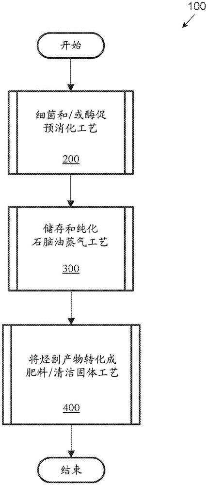
fig. 1 illustrates an exemplary high-outline process (high-level overview process) according to one embodiment of the present disclosure.
Fig. 2 is a flow chart of a predigestion process according to one embodiment of the present disclosure.
Fig. 3 is a flow chart of a process for storing and purifying naphtha vapors in accordance with one embodiment of the present disclosure.
Fig. 4 is a flow chart of an exemplary process for converting hydrocarbons to fertilizer according to one embodiment of the disclosure.
Fig. 5 illustrates a number of exemplary system components according to one embodiment of the present disclosure.
Fig. 6 illustrates exemplary system components according to one embodiment of the present disclosure.
Fig. 7 illustrates exemplary system components according to one embodiment of the present disclosure.
FIG. 8 illustrates an exemplary chemical tote component, in accordance with one embodiment of the present disclosure.
Detailed description of the preferred embodiments
For the purposes of promoting an understanding of the principles of the disclosure, reference will now be made to the embodiments illustrated in the drawings and specific language will be used to describe the same. However, it will be understood that it is not thereby intended to limit the scope of the present disclosure; any alterations and further modifications in the described or illustrated embodiments, and any further applications of the principles of the disclosure as illustrated therein are contemplated as would normally occur to one skilled in the art to which the disclosure relates. All limitations of scope should be determined from the claims and as expressed in the claims.
Whether a term is capitalized is not to be considered a limitation or restriction on the meaning of the term. As used in this document, capitalized terms shall have the same meaning as non-capitalized terms unless the context in which they are used specifically indicates a more restrictive meaning intended for the capitalized terms. However, unless the context clearly indicates that such limitation is intended, capitalization or absence of capitalization in the remainder of this document is not intended to be necessarily limiting.
Furthermore, as used in this specification including the appended claims, the singular forms "a," "an," and "the" include plural referents, and reference to a particular numerical value includes at least the particular value unless the context clearly dictates otherwise. Ranges may be expressed herein as from "about" or "about" one particular value and/or to "about" or "about" another particular value. When such a range is expressed, another embodiment includes from the one particular value and/or to the other particular value. Similarly, when values are expressed as approximations, by use of the antecedent "about," it will be understood that the particular value forms another embodiment.
As will be appreciated by one of ordinary skill in the art, the steps and processes described herein may operate simultaneously and continuously, are typically asynchronous and independent, and do not necessarily occur in the order discussed.
These and other aspects, features and advantages of the claimed disclosure will become apparent from the following detailed written description of embodiments and aspects, taken in conjunction with the following drawings, although variations and modifications of the described aspects, features and advantages may be effected without departing from the spirit and scope of the novel concepts of the disclosure.
Overview of the invention
An exemplary process begins with pretreatment of a hydrocarbonaceous material. The hydrocarbonaceous material can undergo hydrolysis and acidification in order to reduce macromolecules and form organic acids. In various embodiments, a working mixture of bacteria, urea, and water (e.g., "disentangled") may be used to break down (e.g., "disentan") hydrocarbons.
Typically, the process continues with the conversion of the components of the hydrocarbon-containing liquid mixture into gases and vapors. The process may be carried out in an anaerobic digester or the like and may be run at any suitable temperature for converting the hydrocarbonaceous liquid into various types of combustion gases. During this process, some molecules, such as water, amines, and carbonates, can resist decomposition and can be discharged for a variety of additional uses. In some embodiments, the carbonaceous chemical (carbonaceous chemical) creosote may be collected and converted to fertilizer (as discussed herein).
In various embodiments, the disclosed system comprises: a reservoir (e.g., a pre-digestion tank) for preparing the working mixture and biodegrading hydrocarbonaceous material; a plurality of tank collectors (tank collectors) for the viscous material; a pump; a plurality of digesters; a heating reservoir (heating reservoir); a collector for separated combustible fractions of hydrocarbons; a conduit for supplying and removing combustion products; a collector for residual material; a gas condenser; a gas compressor and a plurality of tanks for purifying the combustion products.
In various embodiments, the system may purify the combustion gases through a series of compressors and tanks. The process may continue with the use of a gas scrubber tank or the like designed to effectively and efficiently remove gas contaminants (e.g., ammonia, chlorine, or sulfur compounds). In some embodiments, the gas scrubber tank filled with water functions by dissolving and/or absorbing contaminants into a scrubbing liquid (scrubbing liquid). In various embodiments, the scrubber tank incorporates a recycle drum (recycle drum) and pump to ensure that removal of contaminants is achieved effectively. Typically, the gas may enter a scrubber tank where it contacts a scrubbing liquid (scrubbing fluid) and traps contaminants, which results in the final product of purified water loaded with electrolyte. In various embodiments, the electrolyte-loaded water along with creosote may be stored in a chemical tote to which the above-mentioned working mixture may be added to produce a fertilizer solution.
As will be appreciated, the present disclosure is not limited in terms of the type of tank (e.g., buffer tank manufactured by Global Industrial of Port Washington, NY), digester (e.g., vacuum digester manufactured by Alibaba of china), compressor (e.g., gas compressor manufactured by extaran of Houston, TX), and Pump (e.g., feed Pump manufactured by Pump Supply Inc of Elgin, IL) used (and further discussed below).
Exemplary applications of the disclosed systems and methods generally include the use of end products (e.g., fertilizers, gases, and vapors). In various embodiments, markets for the end products may include industries such as refineries (e.g., use of naphtha streams due to low sulfur content) and agriculture (e.g., use of fertilizers). As will occur to those of ordinary skill in the art, the present disclosure is not limited in its application to the disclosed products in the systems and methods described herein.
Exemplary embodiments
For purposes of illustrating and explaining the basic processes and components of the disclosed systems and methods, referring now to the drawings, with reference to fig. 1, fig. 1 illustrates an exemplary high-level generalized process 100 of one embodiment of the present disclosure. As will be appreciated and appreciated, the exemplary high-level generalized process 100 illustrated in fig. 1 represents only one manner or embodiment of the system and method of the present invention. Various exemplary processes discussed in fig. 1-4 will be further discussed in conjunction with fig. 5-8.
The present disclosure provides processes (and systems) for converting waste materials (e.g., coal, carpet waste (carpet), wood, lump coal, weeds, and plastic pieces of cell phones) into hydrocarbon fuels and fertilizers. The exemplary process 100 includes: bacterial and/or enzymatic pre-digestion process 200; a storage and purification naphtha vapor process 300; and converting the hydrocarbon by-product to fertilizer process 400. In various embodiments, the process 200 may generally produce a solid hydrocarbon and an activated coal slurry. In some embodiments, process 300 may include producing naphtha vapor via a catalytic reduction process, which may be condensed, dehydrated, and stored and/or purified. In some embodiments, process 400 may include converting hydrocarbon byproducts to fertilizer, or other uses. Each of these processes will be discussed in turn.
Turning now to fig. 2, a flow diagram of a predigestion process 200 is shown, according to one embodiment of the present disclosure. The system begins at step 202, where step 202 includes mixing a slurry of raw materials, such as coal fines, with water. In various embodiments, at step 206, the raw material mixture is introduced into a holding tank. In at least one embodiment, the raw materials and water are mixed directly in the holding tank.
In some embodiments, the process continues at step 210, step 210 comprising adding a culture of the specialized bacteria, urea (or amine), and a dispersant to the holding tank. The present disclosure does not address the use of bacteria (e.g., bacillus firmus) and dispersants (e.g., soap or->
 Soap) is limited. In various embodiments, the mixture may have a pH in the range of 7-9. In at least one embodiment, no external heating or cooling is present and the process is run at ambient temperature and pressure. Furthermore, in some embodiments, the mixture breaks down (e.g., "untwists") the hydrocarbons without stirring or further mixing (although in some embodiments, the mixture may be stirred at suitable intervals).
In various embodiments, at step 214, the bacterial culture is multiplied (multiple) and various enzymes (e.g., lipases) may be produced that attack the coal particles, solubilize and extract some hydrocarbons while converting other hydrocarbons into shorter chain hydrocarbons, proteins, or alcohols. In some embodiments, after a suitable time interval, bacteria and enzymes may extract some hydrocarbons, crack other hydrocarbons into shorter chain hydrocarbons, proteins, or alcohols, and generally weaken and degrade the structure of the coal fines, which makes possible further separation of hydrocarbons from the remaining rock/mineral matrix of the coal. As will be appreciated from the discussion herein, the time interval may be any suitable time interval, such as one day, two days, one week, one month, etc.
After step 214, the "predigested" hydrocarbon mixture is further processed to produce naphtha vapors and fertilizer, as discussed further herein.
Turning now to fig. 3, a flow diagram of a process 300 for storing and purifying naphtha vapors in accordance with one embodiment of the present disclosure is shown. Beginning with step 302, the system receives a coal slurry mixture (e.g., a predigested mixture from FIG. 2) in a buffer tank. In at least one embodiment, any free water is withdrawn from the mixture for removal and urea is added and mixed into the contents.
At step 304, the coal slurry is pumped and/or discharged into a vacuum digester where hydrocarbons are further converted to shorter chain hydrocarbons, proteins, and/or alcohols, and water is separated.
At step 306, the lighter components from the coal slurry are removed by catalytic reduction to produce naphtha vapor.
Continuing with the process of the present invention, at step 308, the naphtha vapor is condensed to produce a plurality of liquids including a liquid hydrocarbon mixture.
At step 310, the liquid hydrocarbon mixture may be purified by a series of compressors and tanks.
Fig. 4 depicts a flowchart of an exemplary process 400 for converting hydrocarbons to naphtha vapors and fertilizer according to one embodiment of the disclosure.
The process begins at step 402, where a digester tank (digester tank) receives and processes a hydrocarbon mixture, such as a coal slurry mixture from the process associated with FIG. 2 or combustion gas from the process of FIG. 3. At step 406, the hydrocarbon mixture is vaporized into lighter naphtha vapor. The process continues at step 410 with the naphtha vapors being condensed and separated in step 410 and sent to a naphtha or kerosene pump and stored.
As will be appreciated, at step 402, the digester tank may not vaporize all of the gases produced from the hydrocarbon mixture, and any remaining combustion gases are further processed. In various embodiments, at step 414, the combustion gases are treated in an off-gas accumulator tank (exhaust accumulator tank).
At step 416, a series of scrubber tanks purify and clean the combustion gases and produce electrolyte-loaded water. At step 420, the electrolyte-loaded water along with carbonaceous material (carbonaceous material) creosote formed during process 300 may be stored in a chemical tote. At step 424, additional amounts of urea, dispersant, and specialized bacterial cultures are added to the chemical tote.
At step 428, a fertilizer solution is generated. In various embodiments, the generation of the fertilizer solution at step 428 is initiated by the reaction of a bacterial enzyme and scrubber water with a creosote stream, additional details of which will be discussed in connection with the description of fig. 7 and 8.
Fig. 5-8 illustrate exemplary components of the systems discussed herein. In addition, fig. 5-8 and the discussion related thereto may help explain how the exemplary processes discussed herein may be accomplished via various system components.
Turning now to fig. 5, various exemplary components of a system for accomplishing the processes described herein are shown. In the exemplary embodiment shown in fig. 5, system 500 includes: an enzymatic pre-digestion tank 506, a buffer day tank 520, a tank 518, a vacuum digester 530, a column 548, a condenser 556, a separator tank 560, a gas-liquid separation tank 564, a gas compressor 572, and propane tanks 574, 578.
Typically, tank 506 is used to prepare the working mixture (process 502) and is connected to tank 520 for further biodegradation (process 510) and pump 526. In some embodiments, tank 520 is connected to a vacuum digester 530, vacuum digester 530 being used to collect viscous materials 512, 508, and 528 via pump 526 (process 522). In some embodiments, vacuum digester 530 is connected to heating reservoir 532 and U-shaped tube 536 for collecting combustion gases 538, overflow products 540, and creosote 542. In various embodiments, vacuum digester 530 is connected to column 548 for separating lighter components from heavier components, allowing the vaporized mixture to pass through condenser 556 and separator tank 560, separator tank 560 separating droplets of liquid having a lower vapor pressure (process 554). In further embodiments, separator tank 560 is connected to a gas-liquid separator tank 564 and a gas compressor 572 for separating the vapor into separate components, such as natural gas and propane 574, 578 (process 570).
In various embodiments, at process 502, a combination of slurry of coal fines, water, and a culture of specialized bacteria is introduced into an enzymatic pre-digestion containment tank 506 for decomposing hydrocarbonaceous materials for further processing. In various embodiments, the holding tank 506 may be of any suitable size and may be constructed of any suitable material. In a particular embodiment, the holding tank 506 may have a capacity of 500bbl, be constructed of fiberglass, and may be closed with a roof panel (roof).
In some embodiments, any suitable amounts of urea (or amine) and dispersant (e.g. Soap or->
 Soap) to promote mixing without agitation. Typically, the mixture will achieve a pH in the range of 7-9. In various embodiments, no external heating or cooling need be present, and the process may be run at any suitable ambient temperature and pressure.
In various embodiments, biodegradation of the coal fines may be initiated by any suitable bacteria (e.g., bacillus firmus, etc.). In some embodiments, the mixture added to the pulverized coal may include bacteria, about 0.66% urea by weight (e.g., at least one embodiment, wherein urea treatment is performed daily), about 3% -6% liquid dishwasher soap (liquid dishwasher soap) as an emulsifier (e.g., or->
or-> ) And about 150mL-300mL of 15-15-15 plant fertilizer (e.g., I/O)>
 Or similar fertilizers having 15% nitrogen, 15% phosphorus, and 15% potassium by weight). In at least one embodiment, the mixture may be blended with any suitable crude oil and/or engine oil at 50/50. In some embodiments, during pre-digestion of coal fines, the bacterial culture proliferates and may produce multiple enzymes (e.g., extracellular lipases, etc.).
In a particular embodiment, bacillus firmus bacterial biomass having a weight equal to 5.07 x 10 is supplied to tank 506 in an amount of 0.2wt.% to facilitate the biodegradation process 5 Number of Colony Forming Units (CFU) per gram of biomass. Typically, the number of CFUs increases to 8.15×10 in 24 to 48 hours 9 Amount of biomass per gram. In some embodiments, bacteria may begin to synthesize extracellular enzymes of lipases, which may attack coal particles and solubilize and extract some hydrocarbons while converting other hydrocarbons. In various embodiments, after a suitable time interval, bacteria and enzymes may extract some hydrocarbons, lyse other hydrocarbons, and generally weaken and degrade the structure of the coal fines, which makes it possible for the vacuum digester 530 to separate hydrocarbons from the remaining rock/mineral matrix of the coal.
In some embodiments, at process 510, hydrocarbon and activated coal slurry 508 (from process 502) is pumped to day tank 520. In some embodiments, any suitable amounts of urea (e.g., 1lb-3 lb) and water (e.g., 30 gallons-60 gallons) are additionally added to tank 520. In various embodiments, coal fines, wood chips, and/or recycled carpet 512 may be placed into tank 518 and mixed with any suitable amount of urea (e.g., 1lb-3 lb) and water (e.g., 30 gallons-60 gallons). In various embodiments, canister 520 and canister 518 may be of any suitable size and composed of any suitable material.
In various embodiments, at process 522, the activated coal slurry 508 is pumped/discharged 526 from day tank 520 to vacuum digester 530. In some embodiments, material 512 from tank 518 may be pumped/discharged 526 to vacuum digester 530. In one embodiment, carbonaceous material (e.g., coal slurry 508, coal fines, wood chips, and/or recycled carpet 512, and/or cell phone (or portion thereof) 528) is fed into a vacuum digester 530, and the vacuum digester 530 may comprise a closed vessel equipped with a U-shaped diesel fuel burner lance 536.
In particular embodiments, the U-shaped tubular system within digester 530 allows for movement of carbonaceous material, and during the transport movement, vaporized product vapors are extracted under constant vacuum. In some embodiments, the burner 532 is used to indirectly heat the carbonaceous material and may not be in direct contact with the material. In one embodiment, other solid materials, such as wood, lump coal, chopped carpet fiber (chopped carpet fiber), plastic bottles, weeds, and cell phones 528, may be loaded into the vacuum digester 520 for reduction and consumption. In various embodiments, the carbonaceous material (508, 512, 528) is further converted to a hydrocarbon fuel with the addition of urea and water. In some embodiments, the larger material settles onto a support grid 534 located just above the firetube assembly (firetube assembly). In further embodiments, multiple types of combustion gases (e.g., CO 2 CO, NOX, etc.) 538 may be generated and captured from diesel fuel burner lances 536.
Continuing with process 522, lighter components are released from the carbonaceous material and other feedstock (508, 512, 528) and may rise through any suitable one or more column apparatus 548. In various embodiments, as the temperature inside the vacuum digester 530 increases, heavier hydrocarbons are released and may condense at a double tube heat exchanger (not shown) while lighter components may rise through column 548. In some embodiments, catalytic reduction may occur in the vacuum digester 530. In some embodiments, via catalytic reduction, naphtha vapor 544 can be produced and can also rise through column 548. In particular embodiments, column 548 may be filled with Raschig rings of any suitable size (e.g., 1 inch) and any suitable material (e.g., aluminum).
In some embodiments, a line (not shown) extends from column 548, allowing naphtha vapor 544 and other vapors to travel for further processing. In various embodiments, the lines extending from column 548 may be of any suitable size (e.g., 2 inches) and may be constructed of any suitable material. In various embodiments, from the bottom of the vacuum digester 530, the drain 542 removes creosote, while another drain 540 may be used to drain water, amines, and carbonates.
In various embodiments, at process 554, the released naphtha vapor 544 may exit the packed column 548 and travel to a series of double-tube water-cooled heat exchangers (not shown) where some components may condense and fall into a vertical tank 560. In various embodiments, any suitable condenser and vertical tank apparatus may be used in the process. In some embodiments, the captured liquid product may include water, amines, olefins, alkanes, possibly alcohols, and ketones. As will be appreciated, when the coal is dissolved, a variety of hydrocarbon products are produced.
In some embodiments, vapor that is too light to be effectively condensed with a cooling water facility (e.g., at a double-tube water-cooled heat exchanger) may travel through a vapor-liquid separator tank 564 (last accumulator) to a gas compressor 572, the gas compressor 572 being a motor-driven positive-displacement unit (positive-displacement unit). In various embodiments, any suitable vapor-liquid separation tank apparatus may be used in the process. In further embodiments, any suitable gas compressor device that can reach any suitable ambient atmospheric pressure (e.g., 125psig discharge) can be used in the process. In various embodiments, the compressed vapor may travel to bullet reservoirs (storage bullet tank) 574 and 578.
In some embodiments, there is a manual discharge from the gas-liquid separation tank 564 and "float mud" (e.g., lithium compounds, cobalt compounds, copper compounds, nickel compounds) is stored in a settling tank with a skimmer (skimmer) 568.
In various embodiments, the gas compressor 572 is strong enough to draw vacuum (about 18 "hg) back to the vacuum digester 530 and typically draws naphtha vapor forward through the double tube heat exchanger and the receiver/vapor-liquid separation tank 564. In some embodiments (not shown), the system includes saturated gas equipment to clean and separate the vapor into separate components such as natural gas and propane (which may also be stored in tanks 574 and 578).
Fig. 6 depicts additional system components according to one embodiment of the present disclosure. In the exemplary embodiment shown in fig. 6, the system includes: atmospheric digester lance 604, atmospheric digester 606, column 618, condenser 628, separator tank 630, kerosene pump 636, and naphtha pump 640. Typically, atmospheric digesters 606 are connected to column 618 for purification of the vapor (process 604). In some embodiments, column 618 is connected to condenser 628 and separator tank 630, where the vapor is further separated by either a kerosene pump 636 or a naphtha pump 640 (process 624).
In various embodiments, at process 604, combustion gases from diesel fuel burner lance 604 may be captured. Continuing with process 604, combustion gas 538, diesel fuel 602 may be accumulated in atmospheric digester 606. In various embodiments, creosote 610 is removed from the bottom of atmospheric digester 606, and another drain 614 may be used to drain water, amines, and carbonates. In some embodiments, the mixture of gases is vaporized, allowing the lighter naphtha vapor 620 and/or lighter components to be released and rise through any suitable packed column equipment 618. In at least one embodiment, the combustion gas 645 can be captured and delivered to the scrubber systems discussed herein.
In a particular embodiment, at process 624, the naphtha vapor 620 from the packed column 618 proceeds to a series of double-tube water-cooled heat exchangers 628, where some components condense and proceed into a separator tank 630. In various embodiments, any suitable separator tank (e.g., vertical or horizontal) constructed of any suitable material having a wide range of pressure requirements may be used in the process. In some embodiments, separator tank 630 may be equipped with a filter (not shown) that filters the contents that may reach and/or leave the tank. In one embodiment, separation and/or filtration of the contents may be based on density, force, temperature, direction, velocity, and/or pressure. In various embodiments, the tank 630 is connected to a kerosene pump 636 and a naphtha pump 640, which can further separate naphtha vapors from kerosene. The naphtha vapor and/or kerosene may then be stored in a suitable tank.
FIG. 7 illustrates exemplary system components including: an exhaust gas accumulator tank 704, injectors (712, 716), scrubber tanks (722, 726), scrubber recirculation drum 734, scrubber recirculation pump 738, and internal combustion engine 742. Typically, the off-gas accumulator tank 704 (process 706) is connected to injectors 712, 716, the injectors 712, 716 being used to pump gas and/or vapor to scrubber tanks 722, 726 (process 710). In some embodiments, scrubber tanks 722, 726 produce water loaded with electrolyte and are connected to scrubber recirculation drum 734, scrubber recirculation pump 738, and internal combustion engine 742 (process 730).
In various embodiments, at process 706, the system captures combustion exhaust gases (538, 540) and treats them with: CO produced by combusting diesel at a rate of 5 gallons per hour 2 Water that may be provided to the scrubber tanks (722, 726) and any unburned hydrocarbons or emissions (emissions) that may be drawn to the off-gas accumulator tank 704 by vacuum. In various embodiments, the scrubber tanks (722, 726) may be about 3,000 gallons to 7,000 gallons in capacity and sealed. At process 710, compounds from the off-gas accumulator tank 704 are delivered to injectors (712, 716). In some embodiments, the exhaust gas from the injectors (712, 716) is delivered to a pair of scrubber tanks (722, 726) filled with water and amine. In various embodiments, any suitable scrubber tank (e.g., venturi, orifice tower, spray tower, cyclone spray tower, dynamic tower, tray tower, etc.) may be used in the process.
In at least one embodiment, tank 722 is equipped with an electrical grid 720. In various embodiments, the design of the power grid 720 includes a series of PVC pipes spaced about 1 inch to 2 inches apart and any combination of any suitable material (e.g., copper)A suitable wire. In particular embodiments, the copper wire may be wrapped around the PVC pipe in any suitable direction that allows water to circulate around each individual wire. In some embodiments, the power grid 720 provides an electric field to facilitate the reduction of hydrogen to active ionized species that will react to drive the reaction of carbonate with amine. In some embodiments, the exhaust gas reacts with the amine-water solution and produces urea and/or ammonia, while the CO 2 Is converted into carbonate material in water. In some embodiments, the scrubber system may produce some hydrogen and methane, which are used to help fuel the gasoline engine, which may drive the scrubber pump 738. In at least one embodiment, at higher loads, the scrubber produces nearly enough hydrogen and methane to replace gasoline and completely fuel the engine 742 with scrubber gas. In certain embodiments, a trace amount of gasoline remains in the manifold to power the engine.
In various embodiments, the scrubber water overflows into a buffer tank 726, where the scrubber water is fed to a scrubber pump 728. In at least one embodiment, the system includes a scrubber recirculation pump 734, the scrubber recirculation pump 734 driving two eductor venturi (712, 716) to help facilitate removal of particulate matter, which in turn creates a vacuum to draw off gas vapor to the accumulator vessel 704. In various embodiments, the system recirculates the wash liquor so as to reduce the solids content of the wash liquor. In some embodiments, the scrubber water eventually accumulates electrolyte, which may saturate and precipitate in the scrubber, affecting its operation. Thus, in at least one embodiment, the scrubber can be dumped before the scrubber water reaches saturation, and the accumulated electrolyte can be used in a creosote conversion process (discussed herein).
FIG. 8 illustrates an exemplary chemical tote 804, where the chemical tote 804 will be described in connection with process 802. In various embodiments, at process 802, scrubber water loaded with electrolyte from tanks 722, 726 is converted to fertilizer along with creosote (542, 610). In some embodiments, the creosote oil stream from the digester is stored in any suitable chemical tote 804. In a particular embodiment, the chemical tote 804 can be a four foot cubic polypropylene tank with a threaded top cap and bottom valve.
In various embodiments, creosote (542, 610) is mixed with water, urea, dispersant, and bacterial culture (e.g., bacillus firmus) from scrubber tanks (722, 726). In some embodiments, the bacterial enzymes and scrubber water react with the creosote oil stream to produce a thick fertilizer solution rich in nitrate, carbonate and mineral nutrients. In various embodiments, the mixture may discharge five to ten gallons per day from the bottom valve and back through the top cover, effectively being a stirring/mixing process. In some embodiments, the batch is converted once or twice a day for one to two weeks, occasionally with more urea added as needed. In a particular embodiment, after about two weeks, urea stops producing nitrate and begins producing ammonia, ammonia smell being a signal that conversion is complete and fertilizer is ready for sale.
While various aspects have been described, additional aspects, features, and methods of the claimed disclosure will be readily identifiable to one of ordinary skill in the art in light of the description herein. Many embodiments and adaptations of the present disclosure and the claimed embodiments, as well as many variations, modifications and equivalent arrangements and methods, other than those described herein, will be apparent from or reasonably suggested by the present disclosure and the foregoing description thereof, without departing from the substance or scope of the claims. Furthermore, any order and/or chronological order of the steps of various processes described and claimed herein is considered to be those of the best mode contemplated for carrying out the claimed disclosure. It should also be appreciated that while the steps of various processes may be shown and described as being performed in a preferred order or sequence of times, the steps of any such process are not limited to being performed in any particular order or sequence, and that no such particular indication of achieving a particular desired result is present. In most cases, the steps of such processes may be performed in a variety of different orders and sequences while still falling within the scope of the claimed disclosure. In addition, some steps may be performed simultaneously (simultaneously), contemporaneously (contemporaneous), or in synchronization with other steps.
The embodiments were chosen and described in order to explain the principles of the claimed disclosure and its practical application to enable one skilled in the art to utilize the invention and various embodiments and with various modifications as are suited to the particular use contemplated. Alternative embodiments will become apparent to those skilled in the art to which the claimed disclosure pertains without departing from the spirit and scope of the claimed disclosure. The scope of the claimed disclosure is, therefore, indicated by the appended claims rather than by the foregoing description and the exemplary embodiments described herein.
Claims (17)
Applications Claiming Priority (5)
| Application Number | Priority Date | Filing Date | Title |
|---|---|---|---|
| US201762555410P | 2017-09-07 | 2017-09-07 | |
| US62/555,410 | 2017-09-07 | ||
| US201762568874P | 2017-10-06 | 2017-10-06 | |
| US62/568,874 | 2017-10-06 | ||
| PCT/US2018/050031 WO2019051280A1 (en) | 2017-09-07 | 2018-09-07 | Methods for biological processing of hydrocarbon-containing substances and system for realization thereof |
Publications (2)
| Publication Number | Publication Date |
|---|---|
| CN111542501A CN111542501A (en) | 2020-08-14 |
| CN111542501B true CN111542501B (en) | 2023-05-30 |
Family
ID=65635270
Family Applications (1)
| Application Number | Title | Priority Date | Filing Date |
|---|---|---|---|
| CN201880069908.4A Active CN111542501B (en) | 2017-09-07 | 2018-09-07 | Method for the biological processing of hydrocarbonaceous materials and system for carrying out the method |
Country Status (7)
| Country | Link |
|---|---|
| US (4) | US11104850B2 (en) |
| EP (2) | EP3678999A4 (en) |
| CN (1) | CN111542501B (en) |
| CA (1) | CA3075302A1 (en) |
| RU (1) | RU2020112487A (en) |
| WO (1) | WO2019051280A1 (en) |
| ZA (1) | ZA202002319B (en) |
Family Cites Families (64)
| Publication number | Priority date | Publication date | Assignee | Title |
|---|---|---|---|---|
| GB1481799A (en) * | 1973-11-30 | 1977-08-03 | Coal Ind | Manufacture of coke |
| US4551224A (en) | 1983-12-16 | 1985-11-05 | Texaco Inc. | Coal liquefaction process |
| US5232679A (en) | 1989-05-22 | 1993-08-03 | Jha Mahesh C | Process for production of value-added coproducts from coal and other carbonaceous materials |
| US5336395A (en) | 1989-12-21 | 1994-08-09 | Exxon Research And Engineering Company | Liquefaction of coal with aqueous carbon monoxide pretreatment |
| US5885825A (en) | 1990-08-24 | 1999-03-23 | Brookhaven Science Associates | Biochemical transformation of coals |
| US5256278A (en) | 1992-02-27 | 1993-10-26 | Energy And Environmental Research Center Foundation (Eerc Foundation) | Direct coal liquefaction process |
| US5308477A (en) | 1992-09-03 | 1994-05-03 | University Of Utah | Method for coal liquefaction |
| US5783065A (en) | 1992-09-03 | 1998-07-21 | University Of Utah Research Foundation | Method for coal liquefaction |
| US5338441A (en) | 1992-10-13 | 1994-08-16 | Exxon Research And Engineering Company | Liquefaction process |
| US5454934A (en) | 1992-12-23 | 1995-10-03 | Exxon Research & Engineering Co. | Coal liquefaction using atomically dispersed metals |
| US5490634A (en) | 1993-02-10 | 1996-02-13 | Michigan Biotechnology Institute | Biological method for coal comminution |
| US5332489A (en) | 1993-06-11 | 1994-07-26 | Exxon Research & Engineering Co. | Hydroconversion process for a carbonaceous material |
| JPH0753965A (en) | 1993-08-09 | 1995-02-28 | Nkk Corp | Liquefaction method of coal |
| EP0817763A4 (en) | 1995-03-13 | 2000-05-31 | Jerry W Finney | Biomass reduction and bioremediation processes and products |
| AUPN910296A0 (en) | 1996-04-03 | 1996-05-02 | Environmental Solutions International Ltd | Process and apparatus for the conversion of sludge |
| US6683227B2 (en) * | 2001-06-13 | 2004-01-27 | Gerald M. Platz | Resource recovery of waste organic chemicals by thermal catalytic conversion |
| US6869979B1 (en) | 2001-09-28 | 2005-03-22 | John W. Rich, Jr. | Method for producing ultra clean liquid fuel from coal refuse |
| US7301060B2 (en) * | 2003-03-28 | 2007-11-27 | Ab-Cwt, Llc | Process for conversion of organic, waste, or low-value materials into useful products |
| CN1257252C (en) | 2004-07-30 | 2006-05-24 | 神华集团有限责任公司 | Method for directly liquefying coal |
| US20070272538A1 (en) | 2006-05-26 | 2007-11-29 | Satchell Donald P | Flash pyrolosis method for carbonaceous materials |
| CN101144021B (en) | 2007-02-16 | 2011-11-09 | 淮北中润生物能源技术开发有限公司 | Technique for producing cellulose biomass coal chemical industry fuel |
| US8449632B2 (en) | 2007-05-24 | 2013-05-28 | West Virginia University | Sewage material in coal liquefaction |
| US8597382B2 (en) | 2007-05-24 | 2013-12-03 | West Virginia University | Rubber material in coal liquefaction |
| US8882862B2 (en) | 2007-05-24 | 2014-11-11 | West Virginia University | Method of forming a mesophase pitch from a coal extract suitable for processing to a high value coke |
| US8465561B2 (en) | 2007-05-24 | 2013-06-18 | West Virginia University | Hydrogenated vegetable oil in coal liquefaction |
| US8066785B2 (en) | 2007-07-30 | 2011-11-29 | Recarbon Corp. | Process for recycling waste materials |
| US8404108B2 (en) | 2007-09-20 | 2013-03-26 | Green Source Energy Llc | Extraction of hydrocarbons from hydrocarbon-containing materials and/or processing of hydrocarbon-containing materials |
| EP2220193A1 (en) | 2007-11-16 | 2010-08-25 | Accelergy Shanghai R & D Center Co., Ltd. | Integrated coal-to-liquids process |
| US9708548B2 (en) | 2007-12-04 | 2017-07-18 | Exxonmobil Research And Engineering Company | Hydrocarbon hydroprocessing using bulk catalyst composition |
| US8920639B2 (en) | 2008-02-13 | 2014-12-30 | Hydrocoal Technologies, Llc | Process for improved combustion of fuel solids |
| US9139791B2 (en) | 2008-02-13 | 2015-09-22 | Hydrocoal Technologies, Llc | Processing device for improved utilization of fuel solids |
| US8298404B2 (en) | 2010-09-22 | 2012-10-30 | Auterra, Inc. | Reaction system and products therefrom |
| CO5980161A1 (en) | 2008-09-02 | 2008-11-28 | Univ Nac De Colombia | PREPARATION PROCESS OF USEFUL CATALYSTS IN DIRECT CARBON LICUEFACTION AND THE CATALYST SO OBTAINED |
| AU2009301573B2 (en) | 2008-10-09 | 2013-09-26 | Synfuels China Technology Co., Ltd. | Method and equipment for multistage liquefying of carbonaceous solid fuel |
| US9284494B2 (en) | 2008-11-15 | 2016-03-15 | Uop Llc | Solids management in slurry hydroprocessing |
| WO2010077459A2 (en) * | 2008-12-30 | 2010-07-08 | Jrst, Llc | Microorganism mediated liquid fuels |
| US8674152B1 (en) | 2009-08-19 | 2014-03-18 | Savannah River Nuclear Solutions, Llc | Coal liquefaction by base-catalyzed hydrolysis with CO2 capture |
| US8226821B2 (en) | 2009-08-19 | 2012-07-24 | Macarthur James B | Direct coal liquefaction with integrated product hydrotreating and catalyst cascading |
| CA3011693C (en) | 2009-09-08 | 2021-03-09 | The Ohio State University Research Foundation | Synthetic fuels and chemicals production with in-situ co2 capture |
| CN101665783A (en) * | 2009-09-27 | 2010-03-10 | 福建师范大学 | Method for preparing degradant of Venetian acinetobacter tetradecane by semisolid fermentation method based on using bagasse as immobilized carrier |
| WO2011072180A1 (en) | 2009-12-09 | 2011-06-16 | Green Technology Llc | Separation and extraction of desired recoverable materials from source materials |
| FR2957607B1 (en) | 2010-03-18 | 2013-05-03 | Inst Francais Du Petrole | PROCESS AND CONVERSION PRODUCTS OF CHARCOAL COMPRISING TWO STEPS OF DIRECT LIQUEFACTION IN BOILING BED AND A FIXED BED HYDROCRACKING STEP |
| US8673135B2 (en) | 2010-05-28 | 2014-03-18 | Axens | Coal liquefaction complex with minimal carbon dioxide emissions |
| WO2011163300A2 (en) * | 2010-06-22 | 2011-12-29 | Quantex Research Corporation | Novel hydrogenated solvents for coal liquefaction |
| US9677014B2 (en) | 2011-01-19 | 2017-06-13 | Exxonmobil Chemical Patents Inc. | Process and apparatus for converting hydrocarbons |
| CA2838873C (en) | 2011-06-10 | 2018-08-21 | Steen Brummerstedt Iversen | Process and apparatus for producing liquid hydrocarbon |
| EP2737021A2 (en) | 2011-07-29 | 2014-06-04 | Saudi Arabian Oil Company | Process for stabilization of heavy hydrocarbons |
| US9550943B2 (en) | 2011-10-27 | 2017-01-24 | Raymond Roger Wallage | Efficient oil shale recovery method |
| US9074139B2 (en) | 2011-12-07 | 2015-07-07 | IFP Energies Nouvelles | Process for coal conversion comprising at least one step of liquefaction for the manufacture of aromatics |
| US9163180B2 (en) | 2011-12-07 | 2015-10-20 | IFP Energies Nouvelles | Process for the conversion of carbon-based material by a hybrid route combining direct liquefaction and indirect liquefaction in the presence of hydrogen resulting from non-fossil resources |
| US9045707B2 (en) | 2012-05-17 | 2015-06-02 | Beijing Jinjiao Biomass Chemical Industry Co., Ltd. | Environmental-friendly liquid fuel and production process thereof |
| CN102757127B (en) | 2012-07-13 | 2013-10-23 | 浙江汉蓝环境科技有限公司 | Method for treating coal water slurry gasification wastewater with microbes |
| KR101646890B1 (en) | 2012-10-01 | 2016-08-12 | 그레이트포인트 에너지, 인크. | Agglomerated particulate low-rank coal feedstock and uses thereof |
| US9707532B1 (en) | 2013-03-04 | 2017-07-18 | Ivanhoe Htl Petroleum Ltd. | HTL reactor geometry |
| AU2014238435B2 (en) * | 2013-03-15 | 2017-09-14 | The Board Of Regents Of The University Of Texas System | Processes for liquefying carbonaceous feedstocks and related compositions |
| CN103509596B (en) | 2013-09-29 | 2015-08-26 | 中国石油大学(北京) | A kind of method of processing inferior heavy oil |
| US9222034B2 (en) | 2013-11-19 | 2015-12-29 | Uop Llc | Process for removing a product from coal tar |
| CN103666608A (en) | 2013-11-20 | 2014-03-26 | 中国东方电气集团有限公司 | Alkali lignin gasification coal-water slurry dispersing agent and preparation method thereof |
| FR3014897B1 (en) | 2013-12-17 | 2017-04-07 | Ifp Energies Now | NEW INTEGRATED PROCESS FOR THE TREATMENT OF PETROLEUM LOADS FOR THE PRODUCTION OF LOW SULFUR AND SEDIMENT FIELDS |
| US9669382B2 (en) | 2013-12-20 | 2017-06-06 | Uop Llc | Methods and apparatuses for isomerizing hydrocarbons |
| US9534176B2 (en) | 2014-12-12 | 2017-01-03 | Quantex Research Corporation | Process for depolymerizing coal to co-produce pitch and naphthalene |
| US9732290B2 (en) | 2015-03-10 | 2017-08-15 | Uop Llc | Process and apparatus for cracking hydrocarbons with recycled catalyst to produce additional distillate |
| CN105038836B (en) | 2015-08-21 | 2017-10-20 | 兴阳新能源(宿迁)有限公司 | Coal slime produces light oil processed, combustion gas cracking technology |
| UA112720C2 (en) * | 2015-08-21 | 2016-10-10 | Кероб Лендрушович Арутюнян | METHOD OF BIOLOGICAL PROCESSING OF CARBON SUBSTANCES AND INSTALLATION FOR ITS PERFORMANCE |
-
2018
- 2018-09-07 CN CN201880069908.4A patent/CN111542501B/en active Active
- 2018-09-07 US US16/090,983 patent/US11104850B2/en active Active
- 2018-09-07 RU RU2020112487A patent/RU2020112487A/en unknown
- 2018-09-07 CA CA3075302A patent/CA3075302A1/en active Pending
- 2018-09-07 WO PCT/US2018/050031 patent/WO2019051280A1/en not_active Ceased
- 2018-09-07 EP EP18854214.6A patent/EP3678999A4/en active Pending
- 2018-09-07 EP EP23152822.5A patent/EP4186870A1/en active Pending
-
2020
- 2020-05-04 ZA ZA2020/02319A patent/ZA202002319B/en unknown
-
2021
- 2021-07-21 US US17/381,605 patent/US11655420B2/en active Active
-
2023
- 2023-05-23 US US18/322,029 patent/US12084618B2/en active Active
-
2024
- 2024-08-01 US US18/792,142 patent/US20250188359A1/en active Pending
Non-Patent Citations (1)
| Title |
|---|
| 吴鹏 等主编.煤的液化.《全国煤炭高职高专(成人)"十二五"规划教材 化学工程与工艺》.2013, * |
Also Published As
| Publication number | Publication date |
|---|---|
| RU2020112487A (en) | 2021-10-07 |
| US11655420B2 (en) | 2023-05-23 |
| CA3075302A1 (en) | 2019-03-14 |
| US20210163825A1 (en) | 2021-06-03 |
| ZA202002319B (en) | 2022-12-21 |
| EP3678999A4 (en) | 2021-05-26 |
| EP3678999A1 (en) | 2020-07-15 |
| US20210348059A1 (en) | 2021-11-11 |
| EP4186870A1 (en) | 2023-05-31 |
| US20240110105A1 (en) | 2024-04-04 |
| US11104850B2 (en) | 2021-08-31 |
| US12084618B2 (en) | 2024-09-10 |
| CN111542501A (en) | 2020-08-14 |
| WO2019051280A1 (en) | 2019-03-14 |
| US20250188359A1 (en) | 2025-06-12 |
| RU2020112487A3 (en) | 2021-11-16 |
Similar Documents
| Publication | Publication Date | Title |
|---|---|---|
| US8287732B2 (en) | Integration of anaerobic digestion in an algae-based biofuel system | |
| CN101068906A (en) | Process for conversion of organic waste, or low-value materials into useful products | |
| CN102173508B (en) | Method for producing biogas for vehicles by utilizing high concentration organic wastewater and waste residues | |
| KR20060002888A (en) | Methods and apparatus for converting organics, wastes or low value substances into useful products | |
| BR102013021902A2 (en) | Ethanol and biogas production method, and ethanol installation for ethanol and biogas production | |
| CN103068961A (en) | System for supporting algae growth with adsorbed carbon dioxide | |
| US20140134710A1 (en) | System for the treatment and purification of biogas with elimination of airflow from a scrubber system | |
| CN101017022A (en) | Novel technology for directly using charring gas of biomass as boiler fuel | |
| US8690993B2 (en) | Caustic scrubber system and method for biogas treatment | |
| CN106753483B (en) | A kind of biomass extrusion catalytic pyrolysis device and method containing catalyst separation and regeneration | |
| US20070224669A1 (en) | Self-Pressurizing, Self-Purifying System and Method for Methane Production by Anaerobic Digestion | |
| CN111542501B (en) | Method for the biological processing of hydrocarbonaceous materials and system for carrying out the method | |
| HK40035634B (en) | Methods for biological processing of hydrocarbon-containing substances and system for realization thereof | |
| US9650275B2 (en) | Integrated process for the production of bio-oil from sludge coming from a wastewater purification plant | |
| HK40035634A (en) | Methods for biological processing of hydrocarbon-containing substances and system for realization thereof | |
| Medvedeva et al. | Mathematical modeling of the process of the gas generation and gas purification of the biogas on polygon of residential solid waste | |
| CN105420139B (en) | Halophilic desulfurization strain and application thereof | |
| JP6795707B2 (en) | Organic substance manufacturing equipment | |
| CN106694445A (en) | Device and method for removing oil stain by adopting carbon tetrachloride | |
| Kalsum et al. | Analysis of Flow Rate and Concentration of Mono Ethanol Amine (MEA) in the Biogas Purification Using Absorption Column with Pall Ring Packing. | |
| Katariya et al. | Biogas up-gradation by using packed bed water scrubber. | |
| ZABAVA et al. | Advanced methods of biogas purification–a review | |
| WO2025144070A1 (en) | Waste processing device | |
| US20130032511A1 (en) | Apparatus and processes for production of coal derived oil products | |
| Fang et al. | Research and development at the pilot and scale-up levels for the recovery of high-value bioenergy in MSTP |
Legal Events
| Date | Code | Title | Description |
|---|---|---|---|
| PB01 | Publication | ||
| PB01 | Publication | ||
| SE01 | Entry into force of request for substantive examination | ||
| SE01 | Entry into force of request for substantive examination | ||
| REG | Reference to a national code |
Ref country code: HK Ref legal event code: DE Ref document number: 40035634 Country of ref document: HK |
|
| GR01 | Patent grant | ||
| GR01 | Patent grant |