CN111494023A - Posterior Cruciate Ligament Tibial Guide - Google Patents
Posterior Cruciate Ligament Tibial Guide Download PDFInfo
- Publication number
- CN111494023A CN111494023A CN201910090572.6A CN201910090572A CN111494023A CN 111494023 A CN111494023 A CN 111494023A CN 201910090572 A CN201910090572 A CN 201910090572A CN 111494023 A CN111494023 A CN 111494023A
- Authority
- CN
- China
- Prior art keywords
- guide
- arm
- cruciate ligament
- posterior cruciate
- tibial
- Prior art date
- Legal status (The legal status is an assumption and is not a legal conclusion. Google has not performed a legal analysis and makes no representation as to the accuracy of the status listed.)
- Pending
Links
Images


Classifications
-
- A—HUMAN NECESSITIES
- A61—MEDICAL OR VETERINARY SCIENCE; HYGIENE
- A61B—DIAGNOSIS; SURGERY; IDENTIFICATION
- A61B90/00—Instruments, implements or accessories specially adapted for surgery or diagnosis and not covered by any of the groups A61B1/00 - A61B50/00, e.g. for luxation treatment or for protecting wound edges
- A61B90/10—Instruments, implements or accessories specially adapted for surgery or diagnosis and not covered by any of the groups A61B1/00 - A61B50/00, e.g. for luxation treatment or for protecting wound edges for stereotaxic surgery, e.g. frame-based stereotaxis
- A61B90/11—Instruments, implements or accessories specially adapted for surgery or diagnosis and not covered by any of the groups A61B1/00 - A61B50/00, e.g. for luxation treatment or for protecting wound edges for stereotaxic surgery, e.g. frame-based stereotaxis with guides for needles or instruments, e.g. arcuate slides or ball joints
Landscapes
- Health & Medical Sciences (AREA)
- Surgery (AREA)
- Life Sciences & Earth Sciences (AREA)
- Heart & Thoracic Surgery (AREA)
- Pathology (AREA)
- Oral & Maxillofacial Surgery (AREA)
- Engineering & Computer Science (AREA)
- Biomedical Technology (AREA)
- Nuclear Medicine, Radiotherapy & Molecular Imaging (AREA)
- Medical Informatics (AREA)
- Molecular Biology (AREA)
- Animal Behavior & Ethology (AREA)
- General Health & Medical Sciences (AREA)
- Public Health (AREA)
- Veterinary Medicine (AREA)
- Prostheses (AREA)
Abstract
本发明提供一种后交叉韧带胫骨导向器,涉及医疗器械技术领域,用于解决目前后十字韧带重建手术治疗效果差的技术问题。该后交叉韧带胫骨导向器包括设有导向孔和摆臂滑道的支座;滑动安装在所述导向孔中的导向杆,所述导向杆内设有贯穿其两端的导针滑道;具有调节臂和连接臂的偏心定位摆臂,所述调节臂滑动安装在所述摆臂滑道中,所述连接臂的后端与所述调节臂的远导向孔端连接,所述连接臂的前端设有弯向所述导向杆的胫骨挂钩,所述胫骨挂钩到所述导向杆的轴线的垂直距离为2‑7mm。本发明提供的后交叉韧带胫骨导向器用于辅助确定后十字韧带重建在胫骨平台上的附着点。
The invention provides a posterior cruciate ligament tibial guide, which relates to the technical field of medical devices and is used to solve the technical problem of poor treatment effect of the current posterior cruciate ligament reconstruction surgery. The posterior cruciate ligament tibial guide includes a support provided with a guide hole and a swing arm slideway; a guide rod slidably installed in the guide hole, the guide rod is provided with a guide pin slideway running through both ends thereof; The eccentric positioning swing arm of the adjusting arm and the connecting arm, the adjusting arm is slidably installed in the swing arm slideway, the rear end of the connecting arm is connected with the distal guide hole end of the adjusting arm, and the front end of the connecting arm A tibial hook bent toward the guide rod is provided, and the vertical distance from the tibial hook to the axis of the guide rod is 2-7 mm. The posterior cruciate ligament tibial guide provided by the present invention is used to assist in determining the attachment point of the posterior cruciate ligament reconstruction on the tibial plateau.
Description
技术领域technical field
本发明涉及医疗器械技术领域,尤其涉及一种后十字韧带修复手术用的后交叉韧带胫骨导向器。The invention relates to the technical field of medical devices, in particular to a posterior cruciate ligament tibial guide for posterior cruciate ligament repair surgery.
背景技术Background technique
膝关节是负责支撑人体体重以及使下肢进行屈伸活动的重要关节,其包括股骨远端的股骨髁部、胫骨近端的胫骨平台以及连接股骨髁部和胫骨平台的前十字韧带和后十字韧带,其中,前十字韧带由股骨髁部的后方延伸至胫骨平台的髁间隆起的前方,用于限制胫骨向前移位;后十字韧带由股骨髁部的前方延伸至胫骨平台的髁间隆起的后方,用于限制胫骨向后移位;通过前十字韧带和后十字韧带保持膝关节前后方向的稳定性。The knee joint is an important joint responsible for supporting the body weight and flexing and extending the lower limbs. It includes the femoral condyle at the distal end of the femur, the tibial plateau at the proximal end of the tibia, and the anterior cruciate ligament and the posterior cruciate ligament that connect the femoral condyle and the tibial plateau. Among them, the anterior cruciate ligament extends from the back of the femoral condyle to the front of the intercondylar eminence of the tibial plateau, which is used to limit the anterior displacement of the tibia; the posterior cruciate ligament extends from the front of the femoral condyle to the rear of the intercondylar eminence of the tibial plateau. , used to limit the posterior displacement of the tibia; maintain the stability of the knee joint in the anterior and posterior directions through the anterior cruciate ligament and the posterior cruciate ligament.
由于膝关节是人体内重要的负重关节之一,当人体在行走或剧烈运动时,膝关节需要在短时间内交替受到全身体重和运动加速度的作用,在肌肉保护不力的情况下容易引起膝关节内的十字韧带损伤,例如出现后十字韧带断裂或损伤的现象,在出现后十字韧带断裂或损伤后,常需要通过后十字韧带重建手术治疗。由于后十字韧带的附着点位置(胫骨止点)对后十字韧带束的张力以及维持胫骨向后稳定性具有显著影响,因此,后十字韧带重建手术的难点之一是确定后十字韧带重建在胫骨平台上的附着点。目前常采用依据中心点定位法设计的后交叉韧带胫骨导向器来辅助确定后十字韧带重建的附着点,该后交叉韧带胫骨导向器包括支座以及安装在支座上的导向杆和摆臂,在后十字韧带重建手术过程中,后交叉韧带胫骨导向器的摆臂在膝关节的内侧植入关节腔内,摆臂的前端置于胫骨平台后方距离胫骨止点约10mm处,导向杆的前端定靠在胫骨上,在导向杆的导向滑道内穿入导针,当导针穿透胫骨平台时,导针穿出胫骨平台处为重建韧带的附着点。Since the knee joint is one of the important weight-bearing joints in the human body, when the human body is walking or exercising vigorously, the knee joint needs to be alternately affected by the body weight and movement acceleration in a short period of time, which is easy to cause the knee joint in the case of insufficient muscle protection. Internal cruciate ligament injury, such as the phenomenon of posterior cruciate ligament rupture or injury, often requires posterior cruciate ligament reconstruction surgery after posterior cruciate ligament rupture or injury. Because the location of the attachment point of the posterior cruciate ligament (tibial insertion) has a significant impact on the tension of the posterior cruciate ligament bundle and the maintenance of the posterior stability of the tibia, one of the difficulties in posterior cruciate ligament reconstruction surgery is to determine the location of the posterior cruciate ligament reconstruction in the tibia. An attachment point on the platform. At present, the posterior cruciate ligament tibial guide designed according to the center point positioning method is often used to assist in determining the attachment point of the posterior cruciate ligament reconstruction. During the reconstruction of the posterior cruciate ligament, the swing arm of the posterior cruciate ligament tibial guide is implanted into the joint cavity on the inside of the knee joint. It is fixed on the tibia, and the guide pin is inserted into the guide slide of the guide rod. When the guide pin penetrates the tibial plateau, the place where the guide pin passes through the tibial plateau is the attachment point of the reconstructed ligament.
然而,上述摆臂的前端置于胫骨平台后方距离胫骨止点约10mm处是根据不同的人体平均值获得的,但由于人体个体存在差异,对于不同的人体来说,将摆臂的前端插在胫骨平台后方距离胫骨止点10mm处所确定的后十字韧带重建的附着点差异较大,由此所确定的后十字韧带重建的附着点可能不是理想附着点,导致后十字韧带重建手术治疗效果差。However, the front end of the above-mentioned swing arm is placed about 10mm behind the tibial plateau and the tibial insertion point is obtained according to the average value of different human bodies. The posterior cruciate ligament reconstruction attachment points determined at a distance of 10 mm from the tibial insertion point behind the tibial plateau are quite different, and the determined attachment points of the posterior cruciate ligament reconstruction may not be the ideal attachment point, resulting in poor surgical treatment effect of the posterior cruciate ligament reconstruction.
发明内容SUMMARY OF THE INVENTION
本发明的目的在于提供一种后交叉韧带胫骨导向器,用于确定后十字韧带重建在胫骨平台上的理想附着点,提高后十字韧带重建手术治疗效果。The purpose of the present invention is to provide a posterior cruciate ligament tibial guide, which is used to determine the ideal attachment point of the posterior cruciate ligament reconstruction on the tibial plateau and improve the surgical treatment effect of the posterior cruciate ligament reconstruction.
为了实现上述目的,本发明提供如下技术方案:In order to achieve the above object, the present invention provides the following technical solutions:
本发明提供一种后交叉韧带胫骨导向器,其包括:设有导向孔和摆臂滑道的支座;滑动安装在所述导向孔中的导向杆,所述导向杆内设有贯穿其两端的导针滑道;具有调节臂和连接臂的偏心定位摆臂,所述调节臂滑动安装在所述摆臂滑道中,所述连接臂的后端与所述调节臂的远导向孔端连接,所述连接臂的前端设有弯向所述导向杆的胫骨挂钩,所述胫骨挂钩到所述导向杆的轴线的垂直距离为2-7mm。The invention provides a posterior cruciate ligament tibial guide, which comprises: a support provided with a guide hole and a swing arm slideway; a guide rod slidably installed in the guide hole, the guide rod is provided with a guide rod extending through the two guide rods. The eccentric positioning swing arm with an adjusting arm and a connecting arm, the adjusting arm is slidably installed in the swing arm slideway, and the rear end of the connecting arm is connected with the distal guide hole end of the adjusting arm , the front end of the connecting arm is provided with a tibial hook bent toward the guide rod, and the vertical distance from the tibial hook to the axis of the guide rod is 2-7 mm.
与现有技术相比,本发明提供的后交叉韧带胫骨导向器具有如下优点:Compared with the prior art, the posterior cruciate ligament tibial guide provided by the present invention has the following advantages:
在本发明提供的后交叉韧带胫骨导向器中,由于偏心定位摆臂的前端设有在后十字韧带重建手术过程中钩挂在胫骨平台后侧的胫骨挂钩,由此可以从胫骨平台后侧偏移一定的距离来确定后十字韧带重建在胫骨平台上的理想附着点。由于本发明提供的后交叉韧带胫骨导向器是基于“后十字韧带在胫骨平台上的附着点越靠近胫骨平台的后侧面,越有利于恢复原韧带的作用及关节稳定性”的解剖发现,来确定后十字韧带重建在胫骨平台上的理想附着点,因此,与现有技术相比,采用本发明提供的后交叉韧带胫骨导向器所确定的后十字韧带的附着点比较理想,因此明显提高了后十字韧带重建手术治疗效果。In the posterior cruciate ligament tibial guide provided by the present invention, since the front end of the eccentrically positioned swing arm is provided with a tibial hook that is hooked on the posterior side of the tibial plateau during reconstruction of the posterior cruciate ligament, it can be offset from the posterior side of the tibial plateau. Move a certain distance to determine the ideal attachment point of the posterior cruciate ligament reconstruction on the tibial plateau. Because the posterior cruciate ligament tibial guide provided by the present invention is based on the anatomical discovery that "the attachment point of the posterior cruciate ligament on the tibial plateau is closer to the posterior side of the tibial plateau, the more conducive to restoring the function of the original ligament and joint stability." The ideal attachment point of the posterior cruciate ligament reconstruction on the tibial plateau is determined. Therefore, compared with the prior art, the attachment point of the posterior cruciate ligament determined by the posterior cruciate ligament tibial guide provided by the present invention is more ideal, so the improvement is obviously improved. The effect of posterior cruciate ligament reconstruction surgery.
作为本发明上述后交叉韧带胫骨导向器的一种改进,所述胫骨挂钩到所述导向杆的轴线的垂直距离为5mm。As an improvement of the above-mentioned posterior cruciate ligament tibial guide of the present invention, the vertical distance from the tibial hook to the axis of the guide rod is 5 mm.
作为本发明上述后交叉韧带胫骨导向器的一种改进,所述摆臂滑道为圆弧形滑道,所述调节臂为圆弧形臂。As an improvement of the above-mentioned posterior cruciate ligament tibial guide according to the present invention, the slideway of the swing arm is an arc-shaped slideway, and the adjustment arm is an arc-shaped arm.
作为本发明上述后交叉韧带胫骨导向器的进一步改进,所述调节臂上设有显示所述连接臂与所述导向杆之间夹角的刻度标识,所述摆臂滑道的一侧边缘设置有与所述刻度标识配合的指向标。As a further improvement of the posterior cruciate ligament tibial guide of the present invention, the adjustment arm is provided with a scale mark indicating the angle between the connecting arm and the guide rod, and one edge of the swing arm slideway is provided There are pointers matched with the scale marks.
作为本发明上述后交叉韧带胫骨导向器的进一步改进,所述调节臂上的刻度标识范围为40°-70°。As a further improvement of the above-mentioned posterior cruciate ligament tibial guide of the present invention, the scale mark on the adjustment arm ranges from 40° to 70°.
作为本发明上述后交叉韧带胫骨导向器的另一种改进,所述摆臂滑道为燕尾形滑道,所述调节臂为与所述燕尾形滑道适配的梯形滑轨。As another improvement of the posterior cruciate ligament tibial guide of the present invention, the swing arm slideway is a dovetail slideway, and the adjustment arm is a trapezoid slideway adapted to the dovetail slideway.
作为本发明上述后交叉韧带胫骨导向器的另一种改进,自所述连接臂的前端起,向所述连接臂的后端延伸的一段所述连接臂弯向所述导向杆,且该段所述连接臂的形状与胫骨髁间隆起形状相同或相似。As another improvement of the posterior cruciate ligament tibial guide of the present invention, from the front end of the connecting arm, a section of the connecting arm extending toward the rear end of the connecting arm is bent toward the guide rod, and this section is The shape of the connecting arm is the same as or similar to the shape of the tibial intercondylar eminence.
作为本发明上述后交叉韧带胫骨导向器的另一种改进,所述支座设有与所述摆臂滑道相通的锁紧螺孔,所述锁紧螺孔内设有可与所述调节臂相抵的锁紧螺栓。As another improvement of the above posterior cruciate ligament tibial guide of the present invention, the support is provided with a locking screw hole that communicates with the swing arm slideway, and the locking screw hole is provided with an adjustable arm against the locking bolt.
作为本发明上述后交叉韧带胫骨导向器的另一种改进,所述支座设有与所述摆臂滑道相通的安装孔,所述安装孔内枢装有套管,所述套管伸出所述安装孔外的一端固设有螺母,所述套管内设有内螺纹,所述套管内设有与所述内螺纹适配的螺柱,且所述螺柱可与所述调节臂相抵。As another improvement of the posterior cruciate ligament tibial guide of the present invention, the support is provided with an installation hole communicating with the swing arm slideway, and a sleeve is pivotally installed in the installation hole, and the sleeve extends A nut is fixed at one end out of the mounting hole, an inner thread is arranged in the sleeve, and a stud adapted to the inner thread is arranged in the sleeve, and the stud can be connected with the adjusting arm offset.
作为本发明上述后交叉韧带胫骨导向器的另一种改进,所述支座上设有与所述导向孔相通的调节螺孔,所述调节螺孔内依次设有顶丝、弹簧和挡块,所述弹簧的两端分别与所述顶丝和所述挡块相连,所述导向杆与所述挡块相对侧设有沿所述导向杆轴向分布的锁定凹槽,所述挡块与所述导向杆相对侧设有与所述锁定凹槽相配合的凸齿。As another improvement of the posterior cruciate ligament tibial guide of the present invention, the support is provided with an adjustment screw hole that communicates with the guide hole, and the adjustment screw hole is sequentially provided with a jack wire, a spring and a stopper , the two ends of the spring are respectively connected with the top wire and the block, the opposite side of the guide rod and the block is provided with locking grooves distributed along the axial direction of the guide rod, the block The opposite side of the guide rod is provided with protruding teeth matched with the locking groove.
除了上面所描述的本发明解决的技术问题、构成技术方案的技术特征以及由这些技术方案的技术特征所带来的有益效果外,本发明提供的后交叉韧带胫骨导向器所能解决的其他技术问题、技术方案中包含的其他技术特征以及这些技术特征带来的有益效果,将在具体实施方式中作出进一步详细的说明。In addition to the technical problems solved by the present invention described above, the technical features constituting the technical solutions, and the beneficial effects brought about by the technical features of these technical solutions, other technologies that can be solved by the posterior cruciate ligament tibial guide provided by the present invention The problems, other technical features included in the technical solution, and the beneficial effects brought about by these technical features will be described in further detail in the specific embodiments.
附图说明Description of drawings
为了更清楚地说明本发明实施例或现有技术中的技术方案,下面将对实施例或现有技术描述中所需要使用的附图作一简单地介绍,显而易见地,下面描述中的附图是本发明的一些实施例,对于本领域普通技术人员来讲,在不付出创造性劳动的前提下,还可以根据这些附图获得其他的附图。In order to more clearly illustrate the embodiments of the present invention or the technical solutions in the prior art, the following briefly introduces the accompanying drawings that need to be used in the description of the embodiments or the prior art. Obviously, the accompanying drawings in the following description These are some embodiments of the present invention. For those of ordinary skill in the art, other drawings can also be obtained according to these drawings without creative efforts.
图1为本发明实施例提供的后交叉韧带胫骨导向器的结构示意图;1 is a schematic structural diagram of a posterior cruciate ligament tibial guide provided by an embodiment of the present invention;
图2为图1中支座的结构示意图;Fig. 2 is the structural representation of the support in Fig. 1;
图3为图1中偏心定位摆臂的结构示意图;Fig. 3 is the structural schematic diagram of the eccentric positioning swing arm in Fig. 1;
图4为图1中B-B向的剖视图;Fig. 4 is a sectional view taken along the direction B-B in Fig. 1;
图5为图1中C区的局部剖视图;Fig. 5 is the partial cross-sectional view of C area in Fig. 1;
图6为图1中D处的局部视图。FIG. 6 is a partial view at D in FIG. 1 .
附图标记说明:Description of reference numbers:
1-支座, 2-导向杆,1-Support, 2-Guide rod,
3-偏心定位摆臂, 4-螺母,3-eccentric positioning swing arm, 4-nut,
5-套管, 6-顶丝,5-Sleeve, 6-Top wire,
7-弹簧, 8-挡块,7-spring, 8-stop,
9-螺柱, 10-支座主体,9- Stud, 10- Standoff Body,
11-导向孔, 12-摆臂滑道,11- Guide hole, 12- Swing arm slideway,
13-连接部, 14-凸台部,13-Connecting part, 14-Boss part,
15-指向标, 21-导针滑道,15- Pointer, 21- Guide pin slide,
22-锁定凹槽, 23-滚花旋钮,22- Locking groove, 23- Knurled knob,
24-锯齿, 31-调节臂,24-Sawtooth, 31-Adjusting Arm,
32-连接臂, 33-胫骨挂钩,32 - connecting arm, 33 - tibial hook,
81-凸齿, 16-导针,81-convex, 16-guide pin,
161-定位部, 321-定位孔。161-positioning part, 321-positioning hole.
具体实施方式Detailed ways
在后十字韧带重建手术过程中,目前主要采用依据中心点定位法设计的后交叉韧带胫骨导向器来确定后十字韧带重建在胫骨平台上的附着点,但由于不同人体的个体差异存在差异,因此对于不同的手术对象,采用该后交叉韧带胫骨导向器很难找到理想附着点,导致后十字韧带重建手术治疗效果差。In the process of posterior cruciate ligament reconstruction surgery, the posterior cruciate ligament tibial guide designed according to the center point positioning method is mainly used to determine the attachment point of the posterior cruciate ligament reconstruction on the tibial plateau. For different surgical objects, it is difficult to find an ideal attachment point using the posterior cruciate ligament tibial guide, resulting in poor surgical treatment effect of posterior cruciate ligament reconstruction.
为了解决上述问题,本发明实施例提供了一种依据偏心定位法设计的后交叉韧带胫骨导向器,该后交叉韧带胫骨导向器是依据“后十字韧带在胫骨平台上的附着点越靠近胫骨平台的后侧面,越有利于恢复原韧带的作用及关节稳定性”的解剖发现,该后交叉韧带胫骨导向器包括支座以及滑动安装在支座上的导向杆和偏心定位摆臂,偏心定位摆臂的前端设有胫骨挂钩。在后十字韧带重建手术过程中,偏心定位摆臂前端的胫骨挂钩钩挂在胫骨平台的后侧,自该胫骨挂钩起向胫骨平台的髁间隆起偏移设定距离即为后十字韧带重建在胫骨平台上的理想附着点,因此明显提高了后十字韧带重建手术治疗效果。In order to solve the above problems, the embodiment of the present invention provides a posterior cruciate ligament tibial guide designed according to the eccentric positioning method. The posterior side of the posterior cruciate ligament is more conducive to restoring the function of the original ligament and joint stability.” Anatomical findings, the posterior cruciate ligament tibial guide includes a support, a guide rod slidably installed on the support, and an eccentric positioning swing arm. The front end of the arm is provided with a tibial hook. During the reconstruction of the posterior cruciate ligament, the tibial hook at the front end of the eccentrically positioned swing arm is hooked on the back of the tibial plateau, and the set distance from the tibial hook to the intercondylar eminence of the tibial plateau is the posterior cruciate ligament reconstruction in the posterior cruciate ligament. An ideal attachment point on the tibial plateau, thus significantly improving the surgical outcome of posterior cruciate ligament reconstruction.
为了使本发明实施例的上述目的、特征和优点能够更加明显易懂,下面将结合本发明实施例中的附图,对本发明实施例中的技术方案进行清楚、完整地描述。显然,所描述的实施例仅仅是本发明的一部分实施例,而不是全部的实施例。基于本发明中的实施例,本领域普通技术人员在没有作出创造性劳动的前提下所获得的所有其它实施例,均属于本发明保护的范围。In order to make the above objects, features and advantages of the embodiments of the present invention more clearly and easily understood, the technical solutions in the embodiments of the present invention will be clearly and completely described below with reference to the accompanying drawings in the embodiments of the present invention. Obviously, the described embodiments are only some, but not all, embodiments of the present invention. Based on the embodiments of the present invention, all other embodiments obtained by those of ordinary skill in the art without creative work fall within the protection scope of the present invention.
此外,需要说明的是,以下实施例中所使用的“近侧或近端”“远侧或远端”“前侧”、“后侧”、“内侧”以及“外侧”等,均依照解剖学姿势与指示方向的定义,亦即,以朝向人体头部的一侧称为近侧,朝向脚部的一侧称为远侧;以朝向身体的腹侧称为前侧,朝向身体的背侧称为后侧,以朝向身体的中央线称为内侧,以远离身体的中央线称为外侧。另外,本发明下述实施例虽以人类患者的膝关节为例进行说明,但本发明并不以此为限,亦即,本发明下述实施例中所提供的人体膝关节,也可以适用于其它具有相同或相似解剖结构的动物的膝关节中。In addition, it should be noted that “proximal or proximal”, “distal or distal”, “anterior”, “posterior”, “medial” and “lateral” used in the following embodiments are all based on anatomy The definition of learning posture and indicating direction, that is, the side facing the human head is called the proximal side, the side facing the feet is called the distal side; the side facing the body is called the front side, and the side facing the body is called the back side. The side is called the posterior side, the center line toward the body is called the inside, and the center line away from the body is called the outside. In addition, although the following embodiments of the present invention are described by taking the knee joint of a human patient as an example, the present invention is not limited to this, that is, the human knee joint provided in the following embodiments of the present invention can also be applied in the knee joints of other animals with the same or similar anatomy.
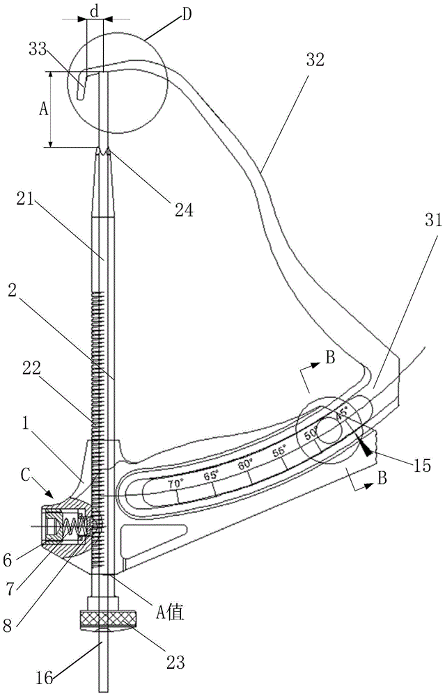
请参阅图1-图3,本发明实施例提供的后交叉韧带胫骨导向器包括支座1、导向杆2和偏心定位摆臂3,其中,支座1设有导向孔11和摆臂滑道12,导向杆2滑动安装在导向孔12中,导向杆2内设有贯穿其两端的导针滑道21;偏心定位摆臂3包括调节臂31和连接臂32,调节臂31滑动安装在摆臂滑道12中,连接臂32的后端与调节臂31的远导向孔端连接,连接臂32的前端设有弯向导向杆2的胫骨挂钩33,胫骨挂钩33到导向杆2的轴线的垂直距离为2-7mm。1-3, the posterior cruciate ligament tibial guide provided by the embodiment of the present invention includes a
具体实施时,支座1包括支座主体10和摆臂支撑部13和和凸台部14,其中,支座主体10内设有导向孔11,摆臂支撑部13和凸台部14位于支座主体10的两侧,且均与支座主体10相连,摆臂支撑部13上形成有摆臂滑道12,在摆臂滑道12的底面以及摆臂滑道外的摆臂支撑部13上还设有多个通孔,以减轻支座1的重量。设置凸台部14,一方面便于在后十字韧带重建手术过程中手持后交叉韧带胫骨导向器,另一方面为了设置下文所述的导向杆锁定装置。上述支座主体10和摆臂支撑部13和和凸台部14可以为铸造成型的一体结构,也可以是采用焊接等方式连为一体的机加件。支座1一般由不锈钢材料制成,例如由沉淀、硬化、马氏体不锈钢(05Cr17Ni4Cu4Nb)制成,使得支座1具有高强度、硬度和抗腐蚀等特性。In specific implementation, the
导向杆2为圆柱状杆,其内部设有与导向杆2的两端贯通的导针滑道21,导针滑道21用于对后十字韧带重建手术过程中使用的导针16进行导向,以便在胫骨平台上有理想的出针点。导向杆2滑动安装在导向孔12中,导向杆2的前端设有便于与胫骨卡和的锯齿24,导向杆的后端设有便于调节导向杆2在导向孔11中位置的滚花旋钮23,且滚花旋钮23为中空结构,以便于导针16进入导针滑道21。导向杆2一般由不锈钢材料制成,例如由沉淀、硬化、马氏体不锈钢(05Cr17Ni4Cu4Nb)制成,使得导向杆2具有高强度、硬度和抗腐蚀等特性。The
偏心定位摆臂3包括调节臂31、连接臂32和胫骨挂钩33,其中,调节臂31和连接臂32的后端连接,两者构成一个“镰刀”状结构。调节臂31安装在摆臂滑道12中,并可在摆臂滑道12中滑动;调节臂31远导向孔端(可滑出摆臂滑道12的一端)与连接臂32的后端连接,连接臂32的前端与胫骨挂钩33连接,胫骨挂钩33到导向杆2的轴线的垂直距离d为2-7mm。该偏心定位摆臂3的设计机理主要是依据“后十字韧带在胫骨平台上的附着点越靠近胫骨平台的后侧面,越有利于恢复原韧带的作用及关节稳定性”解剖发现;以及考虑如果后十字韧带在胫骨平台上的附着点过于靠近近胫骨平台的后侧面,由此形成的胫骨隧道强度可能会不足等情况,因此,本申请发明人依据大量临床经验以及膝关节的解剖试验确定距离d一般为2-7mm,较佳地,胫骨挂钩33到导向杆2的轴线的垂直距离d为5mm。The eccentric positioning swing arm 3 includes an adjusting
当在后十字韧带重建手术中使用上述后交叉韧带胫骨导向器时,在关节镜的帮助下,将偏心定位摆臂3的前端从膝关节的后侧置入关节腔内,将胫骨挂钩33钩挂于胫骨平台的后侧,胫骨平台的后侧距离胫骨平台上后十字韧带的附着点的中心位置(导针16在胫骨平台的出针点位于后十字韧带的附着点的中心位置)距离为5mm左右。然后将导向杆2的前端锯齿24顶靠在胫骨上,从导向杆2的后端,将导针16穿入导针滑道21内,并将导针16植入胫骨内,导针16尖端在胫骨平台上的出针点位置距离胫骨挂钩33的垂直距离为5mm,依据导针16导向建立后十字韧带的植入通道以及后十字韧带重建在胫骨平台上的附着点。When the above-mentioned posterior cruciate ligament tibial guide is used in posterior cruciate ligament reconstruction surgery, with the help of arthroscope, the front end of the eccentric positioning swing arm 3 is placed into the joint cavity from the back side of the knee joint, and the
根据上述描述可知,在本发明实施例中,由于偏心定位摆臂3的前端设有在后十字韧带手术过程中钩挂在胫骨平台后侧的胫骨挂钩33,由此可以从胫骨平台后侧偏移一定的距离来确定重建后十字韧带的在胫骨平台上的附着点。由于利用该后交叉韧带胫骨导向器确定的后十字韧带的附着点符合“后十字韧带在胫骨平台上的附着点越靠近胫骨平台的后侧面,越有利于恢复原韧带的作用及关节稳定性”的解剖发现,因此,利用该后交叉韧带胫骨导向器确定的后十字韧带的附着点比较理想,因此明显提高了后十字韧带重建手术治疗效果。As can be seen from the above description, in the embodiment of the present invention, since the front end of the eccentric positioning swing arm 3 is provided with a
调节臂31在摆臂滑道12内滑动时,可以改变连接臂32与导向杆2之间的夹角,为了便于调整该夹角,优选地,摆臂滑道12为圆弧形滑道,调节臂31为圆弧形臂。此外,为了使操作人员较直观的观察到连接臂32与导向杆2之间的夹角,在一较佳实施例中,调节臂31上设有显示连接臂32与导向杆2之间夹角的刻度标识,调节臂31上的刻度标识范围为40°-70°,如图3中的45°、50°、55°……70°等,摆臂滑道12的一侧边缘设置有与所述刻度标识配合的指向标15,该指向标15指向的刻度标识即为连接臂32与导向杆2之间夹角,例如图1中指向标15指向45°,表示连接臂32与导向杆2之间的夹角为45°。When the adjusting
摆臂滑道12的具体结构形式有多种,例如为矩形滑道、倒三角形滑道或燕尾形滑道,请参阅图4,在一较佳地实施例中,摆臂滑道12为燕尾形滑道,调节臂为与燕尾形滑道适配的梯形滑轨。如此设计,可以防止调节臂31从摆臂滑道12中脱离,以及提高摆臂滑道12对调节臂31的导向准确性。There are many specific structural forms of the
为了便于将胫骨挂钩33钩挂胫骨平台的后侧,防止连接臂32晃动,请参阅图1和图3,在一较佳实施例中,在自连接臂32的前端起,向连接臂32的后端延伸的一段连接臂32弯向导向杆2,且该段连接臂32的形状与胫骨髁间隆起形状相同或相似。也就是说,从连接臂32的前端起的一部分连接臂是弯曲的,且该部分连接臂的弯曲程度与胫骨平台的髁间隆起程度相同或相似,使得胫骨挂钩33钩挂胫骨平台的后侧时,由于连接臂32与胫骨平台的髁间隆起接触的部分的形状与胫骨平台的髁间隆起相同或相似,从而使得连接臂32可与胫骨平台的髁间隆起紧密贴合,防止连接臂32晃动,从而确定出理想的导针16出针点,进而确定后十字韧带重建在胫骨平台上的理想附着点。In order to easily hook the
在后十字韧带重建手术过程中,当连接臂32与导向杆2之间的夹角选定后,一般需要锁定连接臂32与导向杆2之间的夹角。锁定连接臂32与导向杆2之间的夹角的方式有多种,例如,在支座1上设有与摆臂滑道相通的锁紧螺孔,锁紧螺孔内设有可与调节臂相抵的锁紧螺栓。当连接臂32与导向杆2之间的夹角选定后,向锁紧螺孔内侧旋转锁紧螺栓,使锁紧螺栓抵顶在调节臂31上,从而锁定连接臂32与导向杆2之间的夹角。当向锁紧螺孔外侧旋转锁紧螺栓时,锁紧螺栓与调节臂31分离,从而可以接触对连接臂32与导向杆2之间的夹角锁定。During the reconstruction of the posterior cruciate ligament, after the angle between the connecting
在一较佳实施例中,请参阅图1和图4,支座1设有与摆臂滑道12相通的安装孔,安装孔内枢装有套管5,套管5伸出安装孔外的一端固设有螺母4,套管5内设有内螺纹,套管5内设有与内螺纹适配的螺柱9,且螺柱9可与调节臂31相抵。具体地,套管5安装在支座1的安装孔内,并可相对其轴线在该安装孔内转动,套管5的一端伸出支座的安装孔外,并与螺母4固定连接,转动螺母4时带动套管5转动;套管5的内壁设有内螺纹,套管5内设置有与该内螺纹匹配的螺柱9,当套管5转动时,螺柱9可以朝向或远离调节臂31移动,例如,当顺时针旋转螺母4时,螺柱9朝向调节臂31移动,当螺柱9抵顶在调节臂31上后将调节臂31锁定在摆臂滑道12中,从而锁定连接臂32与导向杆2之间的夹角。当逆时针旋转螺母4时,螺柱9远离调节臂31,当螺柱9与调节臂31分离后,调节臂31可以在摆臂滑道12中滑动,从而可以接触对连接臂32与导向杆2之间的夹角锁定。In a preferred embodiment, please refer to FIG. 1 and FIG. 4, the
请继续参阅图1,导向杆2可在导向孔11中滑动,为了便于观察导向杆2的前端到连接臂31的距离A,导向杆2的外表面沿其轴向设置有刻度标识,可以通过观察从支座1后端露出的导向杆2上的刻度标识,确定导向杆2的前端到连接臂31的距离A值。Please continue to refer to FIG. 1, the
当导向杆2的前端到连接臂31的距离A确定后,一般需要将导向杆2锁定在导向孔11中。在一较佳实施例中,请参阅图1和图5,支座1上设有与导向孔11相通的调节螺孔,调节螺孔内依次设有顶丝6、弹簧7和挡块8,弹簧7的两端分别与顶丝6和挡块8相连,导向杆2与挡块8相对侧设有沿导向杆2轴向分布的锁定凹槽22,挡块8与导向杆2相对侧设有与锁定凹槽22相配合的凸齿81。具体地,顶丝6、弹簧7和挡块8设置在调节螺孔内,其中,顶丝6位于最外侧,并与调节螺孔螺纹配合,挡块8位于最内侧,弹簧7位于顶丝6和挡块8之间,且两端分别与顶丝6和挡块8连接。当向调节螺孔内侧旋转顶丝6时,弹簧7将顶丝6向调节螺孔内侧的压力传递给挡块8,挡块8朝向导向杆2移动,直至挡块8的凸齿81与导向杆2的锁定凹槽22卡合,从而将导向杆2锁定在导向孔11中。当向调节螺孔外侧旋转顶丝6时,挡块8远离导向杆2,直至挡块8的凸齿81与导向杆2的锁定凹槽22分离,从而将导向杆2解锁。需要说明的是,弹簧7用于缓解顶丝6对挡块8的压力,避免挡块8对导向杆2的压力过大而损坏导向杆2或导向杆2变形,提高导向杆使用寿命。After the distance A from the front end of the
需要补充的是,上述各实施例中的螺母4、套管5、顶丝6、挡块8和螺柱9均是由不锈钢材料制成,例如由沉淀、硬化、马氏体不锈钢(05Cr17Ni4Cu4Nb)制成,以使上述各部件具有高强度、硬度和抗腐蚀等特性。此外,弹簧7一般采用302不锈钢,以使弹簧具有较佳的弹性;偏心定位摆臂3可选用马氏体不锈钢,例如32Cr13Mo,以使偏心定位摆臂3具有高强度和耐蚀性。It should be added that the
图6为图1中D处的局部视图,请参照图6,导针16都包括在导针16端部形成的定位部161,相应的在连接臂32上设置有定位孔321,使用时导针16端部的定位部161可以插入到定位孔321内,可以对导针16进行精准定位。进一步地,连接臂32上具有定位面,定位孔321开设在定位面上。6 is a partial view of D in FIG. 1 , please refer to FIG. 6 , the guide needles 16 all include a
本说明书中各实施例或实施方式采用递进的方式描述,每个实施例重点说明的都是与其他实施例的不同之处,各个实施例之间相同相似部分相互参见即可。The embodiments or implementations in this specification are described in a progressive manner, and each embodiment focuses on the differences from other embodiments, and the same and similar parts between the various embodiments may be referred to each other.
在本说明书的描述中,参考术语“一个实施方式”、“一些实施方式”、“示意性实施方式”、“示例”、“具体示例”、或“一些示例”等的描述意指结合实施方式或示例描述的具体特征、结构、材料或者特点包含于本发明的至少一个实施方式或示例中。在本说明书中,对上述术语的示意性表述不一定指的是相同的实施方式或示例。而且,描述的具体特征、结构、材料或者特点可以在任何的一个或多个实施方式或示例中以合适的方式结合。In the description of this specification, reference to the terms "one embodiment," "some embodiments," "exemplary embodiment," "example," "specific example," or "some examples", etc., is meant to incorporate the embodiments A particular feature, structure, material, or characteristic described or exemplified is included in at least one embodiment or example of the present invention. In this specification, schematic representations of the above terms do not necessarily refer to the same embodiment or example. Furthermore, the particular features, structures, materials or characteristics described may be combined in any suitable manner in any one or more embodiments or examples.
最后应说明的是:以上各实施例仅用以说明本发明的技术方案,而非对其限制;尽管参照前述各实施例对本发明进行了详细的说明,本领域的普通技术人员应当理解:其依然可以对前述各实施例所记载的技术方案进行修改,或者对其中部分或者全部技术特征进行等同替换;而这些修改或者替换,并不使相应技术方案的本质脱离本发明各实施例技术方案的范围。Finally, it should be noted that the above embodiments are only used to illustrate the technical solutions of the present invention, but not to limit them; although the present invention has been described in detail with reference to the foregoing embodiments, those of ordinary skill in the art should understand that: The technical solutions described in the foregoing embodiments can still be modified, or some or all of the technical features thereof can be equivalently replaced; and these modifications or replacements do not make the essence of the corresponding technical solutions deviate from the technical solutions of the embodiments of the present invention. scope.
Claims (10)
Priority Applications (1)
| Application Number | Priority Date | Filing Date | Title |
|---|---|---|---|
| CN201910090572.6A CN111494023A (en) | 2019-01-30 | 2019-01-30 | Posterior Cruciate Ligament Tibial Guide |
Applications Claiming Priority (1)
| Application Number | Priority Date | Filing Date | Title |
|---|---|---|---|
| CN201910090572.6A CN111494023A (en) | 2019-01-30 | 2019-01-30 | Posterior Cruciate Ligament Tibial Guide |
Publications (1)
| Publication Number | Publication Date |
|---|---|
| CN111494023A true CN111494023A (en) | 2020-08-07 |
Family
ID=71865215
Family Applications (1)
| Application Number | Title | Priority Date | Filing Date |
|---|---|---|---|
| CN201910090572.6A Pending CN111494023A (en) | 2019-01-30 | 2019-01-30 | Posterior Cruciate Ligament Tibial Guide |
Country Status (1)
| Country | Link |
|---|---|
| CN (1) | CN111494023A (en) |
Cited By (1)
| Publication number | Priority date | Publication date | Assignee | Title |
|---|---|---|---|---|
| CN115721374A (en) * | 2022-11-17 | 2023-03-03 | 北京积水潭医院 | Tibia guiding device |
Citations (9)
| Publication number | Priority date | Publication date | Assignee | Title |
|---|---|---|---|---|
| FR2918554A1 (en) * | 2007-07-09 | 2009-01-16 | Amplitude Soc Par Actions Simp | Adjustable drilling jig for drilling posterolateral beam inserting femoral tunnel, has plate whose axis is inclined with respect to arm plane, so that axis of plate is coincidence with large axis of insertion zone in lateral condyle of knee |
| CN201353165Y (en) * | 2009-02-24 | 2009-12-02 | 张强 | Knee joint posterior cruciate ligament tibia locator |
| CN201426740Y (en) * | 2009-06-19 | 2010-03-24 | 南京医科大学附属南京第一医院 | Knee Posterior Cruciate Ligament Reconstruction Positioner |
| CN201664336U (en) * | 2010-04-16 | 2010-12-08 | 邵汝谊 | Tibia sight for rebuilding posterior cruciate ligament |
| CN202604902U (en) * | 2012-03-06 | 2012-12-19 | 北京积水潭医院 | Posterior cruciate ligament merging fossa tendon reconstruction guider under arthroscope |
| CN105395223A (en) * | 2015-12-30 | 2016-03-16 | 山东威高骨科材料股份有限公司 | Tibia guider for conducting eccentric positioning |
| CN105816248A (en) * | 2016-05-02 | 2016-08-03 | 哈尔滨市第医院 | Anterior cruciate ligament tibia end positioning device |
| US20180168665A1 (en) * | 2016-12-21 | 2018-06-21 | University Of Virginia Patent Foundation | Adjustable device for identifying a target location for a tibial tunnel and related method thereof |
| CN209933009U (en) * | 2019-01-30 | 2020-01-14 | 北京大学第三医院(北京大学第三临床医学院) | Posterior cruciate ligament tibia guider |
-
2019
- 2019-01-30 CN CN201910090572.6A patent/CN111494023A/en active Pending
Patent Citations (9)
| Publication number | Priority date | Publication date | Assignee | Title |
|---|---|---|---|---|
| FR2918554A1 (en) * | 2007-07-09 | 2009-01-16 | Amplitude Soc Par Actions Simp | Adjustable drilling jig for drilling posterolateral beam inserting femoral tunnel, has plate whose axis is inclined with respect to arm plane, so that axis of plate is coincidence with large axis of insertion zone in lateral condyle of knee |
| CN201353165Y (en) * | 2009-02-24 | 2009-12-02 | 张强 | Knee joint posterior cruciate ligament tibia locator |
| CN201426740Y (en) * | 2009-06-19 | 2010-03-24 | 南京医科大学附属南京第一医院 | Knee Posterior Cruciate Ligament Reconstruction Positioner |
| CN201664336U (en) * | 2010-04-16 | 2010-12-08 | 邵汝谊 | Tibia sight for rebuilding posterior cruciate ligament |
| CN202604902U (en) * | 2012-03-06 | 2012-12-19 | 北京积水潭医院 | Posterior cruciate ligament merging fossa tendon reconstruction guider under arthroscope |
| CN105395223A (en) * | 2015-12-30 | 2016-03-16 | 山东威高骨科材料股份有限公司 | Tibia guider for conducting eccentric positioning |
| CN105816248A (en) * | 2016-05-02 | 2016-08-03 | 哈尔滨市第医院 | Anterior cruciate ligament tibia end positioning device |
| US20180168665A1 (en) * | 2016-12-21 | 2018-06-21 | University Of Virginia Patent Foundation | Adjustable device for identifying a target location for a tibial tunnel and related method thereof |
| CN209933009U (en) * | 2019-01-30 | 2020-01-14 | 北京大学第三医院(北京大学第三临床医学院) | Posterior cruciate ligament tibia guider |
Cited By (1)
| Publication number | Priority date | Publication date | Assignee | Title |
|---|---|---|---|---|
| CN115721374A (en) * | 2022-11-17 | 2023-03-03 | 北京积水潭医院 | Tibia guiding device |
Similar Documents
| Publication | Publication Date | Title |
|---|---|---|
| JP6557008B2 (en) | Femoral sizing jig, femoral resection system, and method | |
| JP5312047B2 (en) | Guide assembly for guiding cutting to femur and tibia during knee joint replacement | |
| US8828012B2 (en) | Anterior cortex referencing extramedullary femoral cut guide | |
| US8523949B2 (en) | Extracapsular surgical procedure and surgical referencing instrument therefor | |
| US7094241B2 (en) | Method and apparatus for achieving correct limb alignment in unicondylar knee arthroplasty | |
| US4759350A (en) | Instruments for shaping distal femoral and proximal tibial surfaces | |
| US7842042B2 (en) | Convergent tunnel guide apparatus and method | |
| CN104095664B (en) | Distal femur clamp assembly and the distal femur cutting device with this assembly | |
| US5542947A (en) | Slotted patella resection guide and stylus | |
| US20080119938A1 (en) | Knee joint prosthesis for bi-compartmental knee replacement and surgical devices thereof | |
| US9370375B2 (en) | Artificial knee joint and surgical instrument used in artificial knee joint replacement surgery | |
| US20100174379A1 (en) | Knee prostheses | |
| CN104013456A (en) | Femoral orthopaedic surgical instrument including a measurement device and method of use of same | |
| JPH051017B2 (en) | ||
| JP2008540057A (en) | Patellar femoral implant and device | |
| WO2006029346A2 (en) | Extracapsular surgical procedure and surgical referencing instrument therefor | |
| CN107961056A (en) | A kind of line of force measurement angle positioner for knee joint peripheral osteotomy | |
| US11759197B2 (en) | Systems and methods for anchor placement | |
| CN209933009U (en) | Posterior cruciate ligament tibia guider | |
| CN111494023A (en) | Posterior Cruciate Ligament Tibial Guide | |
| GB2398011A (en) | Alignment device for use in orthapaedic surgery | |
| US11529245B2 (en) | Kinematic-axis locating device for knee arthroplasty | |
| CN209951262U (en) | Shin bone cuts bone size measurement ware | |
| CN223569362U (en) | Tibia sagittal osteotomy guide | |
| US20100049199A1 (en) | Tibial guide for acl repair having moveable distal features |
Legal Events
| Date | Code | Title | Description |
|---|---|---|---|
| PB01 | Publication | ||
| PB01 | Publication | ||
| SE01 | Entry into force of request for substantive examination | ||
| SE01 | Entry into force of request for substantive examination |