CN111486421A - Indoor quick detach type L ED controlling means - Google Patents
Indoor quick detach type L ED controlling means Download PDFInfo
- Publication number
- CN111486421A CN111486421A CN202010410555.9A CN202010410555A CN111486421A CN 111486421 A CN111486421 A CN 111486421A CN 202010410555 A CN202010410555 A CN 202010410555A CN 111486421 A CN111486421 A CN 111486421A
- Authority
- CN
- China
- Prior art keywords
- face shell
- control device
- led control
- sliding
- indoor quick
- Prior art date
- Legal status (The legal status is an assumption and is not a legal conclusion. Google has not performed a legal analysis and makes no representation as to the accuracy of the status listed.)
- Pending
Links
Images


Classifications
-
- F—MECHANICAL ENGINEERING; LIGHTING; HEATING; WEAPONS; BLASTING
- F21—LIGHTING
- F21V—FUNCTIONAL FEATURES OR DETAILS OF LIGHTING DEVICES OR SYSTEMS THEREOF; STRUCTURAL COMBINATIONS OF LIGHTING DEVICES WITH OTHER ARTICLES, NOT OTHERWISE PROVIDED FOR
- F21V23/00—Arrangement of electric circuit elements in or on lighting devices
- F21V23/003—Arrangement of electric circuit elements in or on lighting devices the elements being electronics drivers or controllers for operating the light source, e.g. for a LED array
- F21V23/004—Arrangement of electric circuit elements in or on lighting devices the elements being electronics drivers or controllers for operating the light source, e.g. for a LED array arranged on a substrate, e.g. a printed circuit board
-
- F—MECHANICAL ENGINEERING; LIGHTING; HEATING; WEAPONS; BLASTING
- F21—LIGHTING
- F21V—FUNCTIONAL FEATURES OR DETAILS OF LIGHTING DEVICES OR SYSTEMS THEREOF; STRUCTURAL COMBINATIONS OF LIGHTING DEVICES WITH OTHER ARTICLES, NOT OTHERWISE PROVIDED FOR
- F21V23/00—Arrangement of electric circuit elements in or on lighting devices
- F21V23/06—Arrangement of electric circuit elements in or on lighting devices the elements being coupling devices, e.g. connectors
-
- F—MECHANICAL ENGINEERING; LIGHTING; HEATING; WEAPONS; BLASTING
- F21—LIGHTING
- F21Y—INDEXING SCHEME ASSOCIATED WITH SUBCLASSES F21K, F21L, F21S and F21V, RELATING TO THE FORM OR THE KIND OF THE LIGHT SOURCES OR OF THE COLOUR OF THE LIGHT EMITTED
- F21Y2115/00—Light-generating elements of semiconductor light sources
- F21Y2115/10—Light-emitting diodes [LED]
Landscapes
- Engineering & Computer Science (AREA)
- General Engineering & Computer Science (AREA)
- Microelectronics & Electronic Packaging (AREA)
- Casings For Electric Apparatus (AREA)
Abstract
Description
技术领域technical field
本发明涉及室内电源控制装置技术领域,尤其涉及一种室内快拆型LED控制装置。The invention relates to the technical field of indoor power supply control devices, in particular to an indoor quick-release LED control device.
背景技术Background technique
目前主流的灯具电源盒,都采用外壳加PCBA(PCBA为printed circuit boardassembly的英文缩写,即装配印刷电路板意思)加固定侧盖(需要工具才能拆卸)加电缆线组成,这种现有的电源盒存在以下缺陷:At present, the mainstream lighting power supply boxes are composed of shell plus PCBA (PCBA is the English abbreviation of printed circuit board assembly, that is, the meaning of assembling printed circuit board), fixed side cover (requires tools to disassemble) and cables. The box has the following defects:
(1)需要专用工具拆卸,给售后安装及维修带来不便,同时增加的人工成本是很大的;(1) Special tools are required for disassembly, which brings inconvenience to after-sales installation and maintenance, and at the same time increases labor costs;
(2)安装时都必须要用特制的工具来撬开侧盖后,才能有效安装接线,而维修时必须重复撬开侧盖才能正常处理,这样既浪费时间也破环了外壳与侧盖的保护,多次操作就会失效;(2) During installation, special tools must be used to pry open the side cover, so that the wiring can be effectively installed. During maintenance, the side cover must be repeatedly opened to handle it normally, which is a waste of time and damages the casing and the side cover. protection, multiple operations will fail;
(3)安装及拆卸的工作效率低。(3) The work efficiency of installation and disassembly is low.
针对上述的不足,我们发明了一种室内快拆型LED控制装置。In view of the above shortcomings, we have invented an indoor quick-release LED control device.
发明内容SUMMARY OF THE INVENTION
本发明的发明目的在于解决现有电源盒存在需要专用工具拆卸,给售后安装及维修带来不便,同时增加人工成本很大,安装和维修时重复撬开侧盖,易使外壳与侧盖的保护作用失效,安装及拆卸的工作效率低的问题。具体解决方案如下:The purpose of the invention is to solve the problem that the existing power box needs special tools to be disassembled, which brings inconvenience to after-sales installation and maintenance, and at the same time increases labor costs. The protection function is invalid, and the work efficiency of installation and disassembly is low. The specific solutions are as follows:
一种室内快拆型LED控制装置,包括面壳,设于面壳两端的盖板,盖板靠面壳中间的这端,设有按柄,盖板的下方设有接线仓,接线仓位于面壳的两端,面壳内部设有电路板组件,电路板组件两端的接线柱,分别设于面壳两端的接线仓内,底壳设于电路板组件的下方,并扣合于面壳的底部。An indoor quick-release LED control device comprises a face shell, a cover plate arranged at both ends of the face shell, the end of the cover plate near the middle of the face shell is provided with a push handle, a wiring compartment is arranged under the cover plate, and the wiring compartment is located in the middle of the face shell. The two ends of the face case, the inside of the face case are provided with circuit board assemblies, the terminals at both ends of the circuit board assemblies are respectively set in the wiring compartments at both ends of the face case, and the bottom case is arranged below the circuit board assembly and is fastened to the face case. bottom of.
进一步地,所述盖板为滑动盖,滑动盖的两侧分别设有一条滑轨。Further, the cover plate is a sliding cover, and two sides of the sliding cover are respectively provided with a sliding rail.
进一步地,所述接线仓的上端两侧,设有水平平行的两条滑槽,供所述滑轨装入。Further, two horizontal and parallel sliding grooves are provided on both sides of the upper end of the wiring compartment for the sliding rails to be loaded into.
进一步地,所述滑动盖的上面设有下凹的指模。Further, the upper surface of the sliding cover is provided with a concave finger mold.
进一步地,所述按柄的外围设有回弹槽。Further, the periphery of the handle is provided with a rebound groove.
进一步地,所述按柄包括按压台和卡扣销,按柄的一端与面壳连接。Further, the push handle includes a pressing table and a snap pin, and one end of the push handle is connected to the face shell.
进一步地,所述卡扣销与所述滑动盖的前端下侧的卡扣定位条卡接。Further, the latching pin is latched with the latching positioning strip on the lower side of the front end of the sliding cover.
进一步地,所述滑动盖的后端两侧分别设有一个定位块,定位块与所述滑轨的端部连接并形成凸起,该定位块与所述滑槽的端部设置的定位槽匹配并靠接。Further, two sides of the rear end of the sliding cover are respectively provided with a positioning block, the positioning block is connected with the end of the sliding rail and forms a protrusion, and the positioning block is connected with the positioning groove provided at the end of the sliding groove. Match and dock.
进一步地,所述滑动盖的后端端部,设有向下的压线板,压线板的下方为所述面壳端部的线槽。Further, the rear end of the sliding cover is provided with a downward pressure plate, and the lower part of the pressure plate is the wire groove of the end of the face shell.
进一步地,所述接线仓由所述面壳端部内部的L型隔离墙,及面壳两侧板围接而成。Further, the wiring compartment is formed by enclosing an L-shaped partition wall inside the end of the face shell and two side plates of the face shell.
综上所述,采用本发明的技术方案具有以下有益效果:To sum up, adopting the technical scheme of the present invention has the following beneficial effects:
本发明解决了现有电源盒存在需要专用工具拆卸,给售后安装及维修带来不便,同时增加人工成本很大,安装和维修时重复撬开侧盖,易使外壳与侧盖的保护作用失效,安装及拆卸的工作效率低的问题。为了克服现有的固定侧盖安装方式的缺陷,提高安装效率,减少人工付出,杜绝重复维修的不安全性。本发明采用了滑动盖快拆装置的特殊结构,具有以下的优点:The invention solves the problem that the existing power box needs special tools to be disassembled, which brings inconvenience to after-sales installation and maintenance, and at the same time increases labor costs. , The problem of low efficiency of installation and disassembly. In order to overcome the defects of the existing fixed side cover installation methods, improve the installation efficiency, reduce labor costs, and eliminate the unsafety of repeated maintenance. The present invention adopts the special structure of the sliding cover quick release device, and has the following advantages:
(1)可在不使用工具的情况下,用手指轻轻按下按柄,同时推动滑动盖上的指模处,就能快速拆装滑动盖,既提高了工作效率,并且反复拆装滑动盖与面壳,也不会使LED控制装置受任何损伤。弹性的按柄及回弹槽结构,不仅方便滑动盖拆开,按柄上的卡扣销可锁紧滑动盖下侧的卡扣定位条,确保了滑动盖不会松开。(1) The sliding cover can be disassembled and assembled quickly by pressing the handle lightly with your fingers and pushing the finger mold on the sliding cover without using tools, which not only improves the work efficiency, but also can be disassembled and assembled repeatedly. The cover and face case will not cause any damage to the LED control device. The elastic push handle and rebound groove structure not only facilitates the disassembly of the sliding cover, but also the buckle pin on the handle can lock the buckle positioning strip on the lower side of the sliding cover, ensuring that the sliding cover will not be loosened.
(2)打破了传统化的侧盖结构,降低了系列产品的开发成本,及售后安装与维修成本,更提高了产品的安全性。(2) It breaks the traditional side cover structure, reduces the development cost of series products, as well as the after-sales installation and maintenance cost, and improves the safety of the product.
(3)面壳壳体与滑动盖采用卡扣滑动式结构,安全高效,实现了快拆的功能。(3) The shell shell and the sliding cover adopt a snap-on sliding structure, which is safe and efficient, and realizes the function of quick release.
(4)全新的快拆卡扣滑动式结构设计,使用同一个卡扣滑动盖式结构,可用于在不同的领域中,其外形可以根据结构变化而变化,快速的拆装可达到投入少、样式多,打破传统式固定结构,突出整个行业独一无二的卖点。(4) The new quick-release buckle sliding structure design uses the same buckle sliding cover structure, which can be used in different fields, and its shape can be changed according to structural changes, and rapid disassembly and assembly can achieve less investment, There are many styles, breaking the traditional fixed structure and highlighting the unique selling point of the entire industry.
(5)本发明的实用性强、通用性好。(5) The present invention has strong practicability and good versatility.
附图说明Description of drawings
为了更清楚地说明本发明实施例的技术方案,下面将对本发明实施例的描述中所需要使用的附图作简单地介绍。显而易见地,下面描述中的附图仅仅是本发明的一部分实施例,对于本领域普通技术人员来讲,在不付出创造性劳动性的前提下,还能够根据这些附图获得其他的附图。In order to illustrate the technical solutions of the embodiments of the present invention more clearly, the following briefly introduces the accompanying drawings that are used in the description of the embodiments of the present invention. Obviously, the drawings in the following description are only a part of the embodiments of the present invention, and for those of ordinary skill in the art, other drawings can also be obtained from these drawings without creative effort.
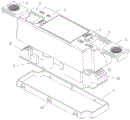
图1为本发明一种室内快拆型LED控制装置的爆炸图;1 is an exploded view of an indoor quick-release LED control device of the present invention;
图2为本发明一种室内快拆型LED控制装置的局部结构图;2 is a partial structural diagram of an indoor quick-release LED control device according to the present invention;
图3为本发明的滑动盖的结构图;Fig. 3 is the structure diagram of the sliding cover of the present invention;
图4为本发明的面壳的结构图。FIG. 4 is a structural diagram of the face shell of the present invention.
附图标记说明:Description of reference numbers:
1-面壳,2-按柄,3-接线仓,4-电路板组件,5-底壳,6-滑动盖,11-回弹槽,12-线槽,13-L型隔离墙,14-螺钉槽,15-扣孔,16-支撑柱,21-按压台,22-卡扣销,31-滑槽,32-定位槽,41-接线柱,51-扣块,61-滑轨,62-指模,63-卡扣定位条,64-定位块,65-压线板。1-face shell, 2-press handle, 3-connection compartment, 4-circuit board assembly, 5-bottom shell, 6-slide cover, 11-rebound groove, 12-wire groove, 13-L-shaped partition wall, 14 -Screw slot, 15-Button hole, 16-Support column, 21-Press table, 22-Snap pin, 31-Slide slot, 32-Location slot, 41-Binding post, 51-Button block, 61-Slide rail, 62-finger die, 63-buckle positioning strip, 64-positioning block, 65-crimping plate.
具体实施方式Detailed ways
下面将结合本发明实施例中的附图,对本发明实施例中的技术方案进行清楚、完整地描述。显然,所描述的实施例仅仅是本发明一部分实施例,而不是全部的实施例。基于本发明中的实施例,本领域普通技术人员在没有作出创造性劳动前提下所获得的所有其他实施例,都属于本发明保护的范围。The technical solutions in the embodiments of the present invention will be clearly and completely described below with reference to the accompanying drawings in the embodiments of the present invention. Obviously, the described embodiments are only some, but not all, embodiments of the present invention. Based on the embodiments of the present invention, all other embodiments obtained by those of ordinary skill in the art without creative efforts shall fall within the protection scope of the present invention.
如图1至4所示,一种室内快拆型LED控制装置,包括面壳1,设于面壳1两端的盖板,盖板靠面壳1中间的这端,设有按柄2,盖板的下方设有接线仓3,接线仓3位于面壳1的两端(实际上接线仓3与面壳1为一体的结构),面壳1内部设有电路板组件4(电路板组件4包括电路板和元器件),电路板组件4两端的接线柱41,分别设于面壳1两端的接线仓3内,底壳5设于电路板组件4的下方,并扣合于面壳1的底部(面壳1的底部内侧设有多个扣孔15,底壳5两侧向外设有多个扣块51,扣块51与扣孔15匹配并扣合固定)。面壳1的两对角上,分别设有一个螺钉槽14,供LED控制装置安装固定之用。As shown in Figures 1 to 4, an indoor quick-release LED control device includes a
进一步地,盖板为滑动盖6,滑动盖6的两侧分别设有一条滑轨61。Further, the cover plate is a
进一步地,接线仓3的上端两侧,设有水平平行的两条滑槽31,供滑轨61装入。Further, two horizontal and parallel sliding
进一步地,滑动盖6的上面设有下凹的指模62。Further, the upper surface of the sliding
进一步地,按柄2的外围设有回弹槽11,回弹槽11为槽孔结构。Further, a
进一步地,按柄2包括按压台21和卡扣销22,按柄2的一端与面壳1连接。(实际上按柄2与面壳1为一体的结构)Further, the
进一步地,卡扣销22与滑动盖6的前端(先插入滑槽31的这端为前端)下侧的卡扣定位条63卡接。Further, the latching
进一步地,滑动盖6的后端两侧,分别设有一个定位块64,定位块64与滑轨61的端部(指后端端部)连接并形成凸起,该定位块64与滑槽31的端部(指靠外的这端端部)设置的定位槽32匹配并靠接。Further, two sides of the rear end of the sliding
进一步地,滑动盖6的后端端部,设有向下的压线板65,压线板的下方为面壳1端部的线槽12,线槽12供接于接线柱41上的导线(图中未画出)通过,压线板65具有压紧导线,不让其松动的作用。实际上,滑轨61、指模62、卡扣定位条63、定位块64、压线板65均为一体的结构设计,组成一个整体的滑动盖6。Further, the rear end of the sliding
进一步地,接线仓3由面壳1端部内部的L型隔离墙13(提高安全间隔级别之用),及面壳两侧板围接而成。接线仓3及滑动盖6的闭合式设计,提高了LED控制装置的安全性。Further, the
本发明的两个接线仓3、两个滑动盖6、底壳5,为对称式设计,可节约模具及生产的成本。面壳1的内部,设有电路板组件4的多个支撑柱16(同时支撑柱16兼有面壳1加强筯的作用),省去了用螺钉固定电路板组件4的麻烦,同时加快了装配速度。The two
综上所述,采用本发明的技术方案具有以下有益效果:To sum up, adopting the technical scheme of the present invention has the following beneficial effects:
本发明解决了现有电源盒存在需要专用工具拆卸,给售后安装及维修带来不便,同时增加人工成本很大,安装和维修时重复撬开侧盖,易使外壳与侧盖的保护作用失效,安装及拆卸的工作效率低的问题。为了克服现有的固定侧盖安装方式的缺陷,提高安装效率,减少人工付出,杜绝重复维修的不安全性。本发明采用了滑动盖快拆装置的特殊结构,具有以下的优点:The invention solves the problem that the existing power box needs special tools to be disassembled, which brings inconvenience to after-sales installation and maintenance, and at the same time increases labor costs. , The problem of low efficiency of installation and disassembly. In order to overcome the defects of the existing fixed side cover installation methods, improve the installation efficiency, reduce labor costs, and eliminate the unsafety of repeated maintenance. The present invention adopts the special structure of the sliding cover quick release device, and has the following advantages:
(1)可在不使用工具的情况下,用手指轻轻按下按柄2(也就是按压按压台21),同时推动滑动盖6上的指模62处,就能快速拆装滑动盖6,既提高了工作效率,并且反复拆装滑动盖6与面壳1,也不会使LED控制装置受任何损伤。弹性的按柄2及回弹槽11结构,不仅方便滑动盖6拆开,按柄2上的卡扣销22可锁紧滑动盖6下侧的卡扣定位条63,确保了滑动盖6不会松开。(1) The sliding
(2)打破了传统化的侧盖结构,降低了系列产品的开发成本,及售后安装与维修成本,更提高了产品的安全性。(2) It breaks the traditional side cover structure, reduces the development cost of series products, as well as the after-sales installation and maintenance cost, and improves the safety of the product.
(3)面壳1壳体与滑动盖6采用卡扣滑动式结构,安全高效,实现了快拆的功能。(3) The
(4)全新的快拆卡扣滑动式结构设计,使用同一个卡扣滑动盖式结构,可用于在不同的领域中,其外形可以根据结构变化而变化,快速的拆装可达到投入少、样式多,打破传统式固定结构,突出整个行业独一无二的卖点。(4) The new quick-release buckle sliding structure design uses the same buckle sliding cover structure, which can be used in different fields, and its shape can be changed according to structural changes, and rapid disassembly and assembly can achieve less investment, There are many styles, breaking the traditional fixed structure and highlighting the unique selling point of the entire industry.
(5)本发明的实用性强、通用性好。(5) The present invention has strong practicability and good versatility.
以上所述的实施方式,并不构成对该技术方案保护范围的限定。任何在上述实施方式的精神和原则之内所作的修改、等同替换和改进等,均应包含在该技术方案的保护范围之内。The above-mentioned embodiments do not constitute a limitation on the protection scope of the technical solution. Any modifications, equivalent replacements and improvements made within the spirit and principles of the above-mentioned embodiments shall be included within the protection scope of this technical solution.
Claims (10)
Priority Applications (1)
| Application Number | Priority Date | Filing Date | Title |
|---|---|---|---|
| CN202010410555.9A CN111486421A (en) | 2020-05-15 | 2020-05-15 | Indoor quick detach type L ED controlling means |
Applications Claiming Priority (1)
| Application Number | Priority Date | Filing Date | Title |
|---|---|---|---|
| CN202010410555.9A CN111486421A (en) | 2020-05-15 | 2020-05-15 | Indoor quick detach type L ED controlling means |
Publications (1)
| Publication Number | Publication Date |
|---|---|
| CN111486421A true CN111486421A (en) | 2020-08-04 |
Family
ID=71792047
Family Applications (1)
| Application Number | Title | Priority Date | Filing Date |
|---|---|---|---|
| CN202010410555.9A Pending CN111486421A (en) | 2020-05-15 | 2020-05-15 | Indoor quick detach type L ED controlling means |
Country Status (1)
| Country | Link |
|---|---|
| CN (1) | CN111486421A (en) |
Cited By (1)
| Publication number | Priority date | Publication date | Assignee | Title |
|---|---|---|---|---|
| CN114237116A (en) * | 2021-12-16 | 2022-03-25 | 深圳市蓝蓝软件有限公司 | USB communication control device and communication control method for numerical control machine tool |
Citations (5)
| Publication number | Priority date | Publication date | Assignee | Title |
|---|---|---|---|---|
| CN201576411U (en) * | 2009-12-11 | 2010-09-08 | 深圳雷曼光电科技股份有限公司 | Box body and led display module |
| CN201995252U (en) * | 2011-01-31 | 2011-09-28 | 亚洲光学股份有限公司 | Protective cover assembly of electronic device |
| CN206165045U (en) * | 2016-10-13 | 2017-05-10 | 广州视源电子科技股份有限公司 | Shell cover plate and electronic product thereof |
| US20180315356A1 (en) * | 2017-04-27 | 2018-11-01 | Manufacturing Resources International, Inc. | Field serviceable and replaceable display assembly |
| CN211952691U (en) * | 2020-05-15 | 2020-11-17 | 天宝电子(惠州)有限公司 | An indoor quick-release LED control device |
-
2020
- 2020-05-15 CN CN202010410555.9A patent/CN111486421A/en active Pending
Patent Citations (5)
| Publication number | Priority date | Publication date | Assignee | Title |
|---|---|---|---|---|
| CN201576411U (en) * | 2009-12-11 | 2010-09-08 | 深圳雷曼光电科技股份有限公司 | Box body and led display module |
| CN201995252U (en) * | 2011-01-31 | 2011-09-28 | 亚洲光学股份有限公司 | Protective cover assembly of electronic device |
| CN206165045U (en) * | 2016-10-13 | 2017-05-10 | 广州视源电子科技股份有限公司 | Shell cover plate and electronic product thereof |
| US20180315356A1 (en) * | 2017-04-27 | 2018-11-01 | Manufacturing Resources International, Inc. | Field serviceable and replaceable display assembly |
| CN211952691U (en) * | 2020-05-15 | 2020-11-17 | 天宝电子(惠州)有限公司 | An indoor quick-release LED control device |
Cited By (1)
| Publication number | Priority date | Publication date | Assignee | Title |
|---|---|---|---|---|
| CN114237116A (en) * | 2021-12-16 | 2022-03-25 | 深圳市蓝蓝软件有限公司 | USB communication control device and communication control method for numerical control machine tool |
Similar Documents
| Publication | Publication Date | Title |
|---|---|---|
| CN211952691U (en) | An indoor quick-release LED control device | |
| CN101752759A (en) | Connector device | |
| CN111486421A (en) | Indoor quick detach type L ED controlling means | |
| TW358860B (en) | Double or multiple auger suction unit for hoods, ovens and similar appliances | |
| CN101853750A (en) | Miniature circuit breakers for side plug-in installation | |
| CN206441964U (en) | A kind of power outlet of improvement type | |
| CN201408719Y (en) | Miniature circuit breaker with plug-in structure | |
| CN215419030U (en) | Outdoor power distribution cabinet of ordered power utilization control system | |
| CN214673585U (en) | Electric automatization distribution cabinet | |
| CN109066234A (en) | A kind of modular switch socket | |
| CN214957479U (en) | A power plug that is easy to disassemble and repair | |
| CN207947986U (en) | A kind of mounting structure of integrated circuit board | |
| CN221467047U (en) | Combined structure of electronic element mounting plate and distribution box | |
| CN208722110U (en) | A kind of computer circuit board | |
| CN209643145U (en) | A kind of PLC rack being easily changed element | |
| CN219267958U (en) | Power plug convenient to dismouting | |
| CN210958646U (en) | Insert wall repeater | |
| US3210609A (en) | Explosion-proof panel board with offset mounting | |
| CN219760345U (en) | Distribution cabinet terminal arrangement structure | |
| CN205105081U (en) | Power module of circuit breaker intelligent control ware | |
| CN214504301U (en) | Heat dissipation type hanging industrial computer | |
| CN218940325U (en) | Pin-connected panel block terminal convenient to dismantle | |
| CN218300654U (en) | Split type block terminal | |
| CN222089900U (en) | Circuit board mounting housing | |
| CN219268149U (en) | A circuit breaker protection measurement and control device |
Legal Events
| Date | Code | Title | Description |
|---|---|---|---|
| PB01 | Publication | ||
| PB01 | Publication | ||
| SE01 | Entry into force of request for substantive examination | ||
| SE01 | Entry into force of request for substantive examination | ||
| CB02 | Change of applicant information |
Country or region after: China Address after: 516005 Shuikou Industrial Zone, Shuikou, Zhenlong, Guangdong, Huizhou Applicant after: Guangdong Tianbao Electronic Technology Co.,Ltd. Applicant after: Huizhou Tianbao Chuang Neng Technology Co.,Ltd. Applicant after: HUIZHOU JINHU INDUSTRIAL DEVELOPMENT Co.,Ltd. Address before: Dongjiang Industrial Zone, Shuikou Town, Huicheng District, Huizhou City, Guangdong Province Applicant before: TEN PAO ELECTRONICS (HUIZHOU) Co.,Ltd. Country or region before: China Applicant before: Huizhou Tianbao Chuang Neng Technology Co.,Ltd. Applicant before: HUIZHOU JINHU INDUSTRIAL DEVELOPMENT Co.,Ltd. |
|
| CB02 | Change of applicant information | ||
| RJ01 | Rejection of invention patent application after publication |
Application publication date: 20200804 |
|
| RJ01 | Rejection of invention patent application after publication |