Picture processing method, device, electronic equipment and computer readable medium
Technical Field
Embodiments of the present disclosure relate to the field of computer technology, and in particular, to a method, an apparatus, an electronic device, and a computer readable medium for processing a picture.
Background
The picture processing technology can comprise a technology that a computer or a terminal automatically clips pictures according to clipping proportion required by a user. Compared with the traditional picture cutting, the method omits the operation step of cutting by a user, thereby simplifying the cutting step.
However, for pictures of different purposes, the importance degree of the foreground object is different, and the clipping result of the automatic clipping cannot be different according to the importance degree of the foreground object, so that the requirement of a user is difficult to meet. Furthermore, in the case of a plurality of foreground objects densely distributed, the clipping results of the automatic clipping described above tend to be unexpected clipping to important foreground objects.
Disclosure of Invention
This summary is provided to introduce a selection of concepts in a simplified form that are further described below in the detailed description. This summary is not intended to identify key features or essential features of the claimed subject matter, nor is it intended to be used to limit the scope of the claimed subject matter.
Some embodiments of the present disclosure propose a picture processing method, apparatus, device/terminal/server and computer readable medium to solve the technical problems mentioned in the background section above.
In a first aspect, some embodiments of the present disclosure provide a picture processing method, including: detecting an object displayed in a target picture to obtain object information, wherein the object information comprises range information for representing the display range of the object; constructing a score map according to the range information, wherein the numerical value at the corresponding position of the display range of the object in the score map is different from the numerical value at the position outside the display range of the object; generating a direction position vector associated with the direction; and determining a clipping region of the target picture according to the direction position vector and the score diagram.
In a second aspect, some embodiments of the present disclosure provide a picture processing apparatus, the apparatus including: a detection unit configured to detect an object displayed in a target picture to obtain object information, the object information including range information for characterizing a display range of the object; a construction unit configured to construct a score map in which a numerical value at a corresponding position of a display range of an object is different from a numerical value at a position outside the display range of the object, based on the range information; a first generation unit configured to generate a direction position vector relating to a direction; and a determining unit configured to determine a clipping region of the target picture based on the score map.
In a third aspect, some embodiments of the present disclosure provide an electronic device comprising: one or more processors; and a storage device having one or more programs stored thereon, which when executed by the one or more processors cause the one or more processors to implement the method as in any of the first aspects.
In a fourth aspect, some embodiments of the present disclosure provide a computer readable medium having a computer program stored thereon, wherein the program, when executed by a processor, implements a method as in any of the first aspects.
One of the above embodiments of the present disclosure has the following advantageous effects: first, by detecting an object displayed in a target picture, object information, which may include range information, can be obtained. Then, a score map is constructed based on the object information. Next, a direction position vector associated with the direction is generated. And finally, determining a clipping region of the target picture according to the direction position vector and the score map. Specifically, the importance degree of the object displayed in the target picture can be represented by the score map. Further, by the above-described directional position vector, it can be determined whether or not the object in the target picture can be cut out. Therefore, according to the direction position vector and the clipping region determined by the importance degree, not only is the importance degree of the object reflected by the clipped result picture, but also whether the display range of the object can be clipped can be distinguished, and the pertinence of the clipping region is improved.
Drawings
The above and other features, advantages, and aspects of embodiments of the present disclosure will become more apparent by reference to the following detailed description when taken in conjunction with the accompanying drawings. The same or similar reference numbers will be used throughout the drawings to refer to the same or like elements. It should be understood that the figures are schematic and that elements and components are not necessarily drawn to scale.
1-5 are schematic diagrams of one application scenario of a method for processing pictures according to some embodiments of the present disclosure;
FIG. 6 is a flow chart of some embodiments of a method for processing pictures according to the present disclosure;
FIG. 7 is a flow chart of further embodiments of a method for processing pictures according to the present disclosure;
FIG. 8 is a schematic illustration of an application scenario of some embodiments of adjusting clipping regions according to the present disclosure;
fig. 9 is a schematic structural view of some embodiments of an apparatus for processing pictures according to the present disclosure;
fig. 10 is a schematic structural diagram of an electronic device suitable for use in implementing some embodiments of the present disclosure.
Embodiments of the present disclosure will be described in more detail below with reference to the accompanying drawings. While certain embodiments of the present disclosure are shown in the drawings, it should be understood that the present disclosure may be embodied in various forms and should not be construed as limited to the embodiments set forth herein. Rather, these embodiments are provided so that this disclosure will be thorough and complete. It should be understood that the drawings and embodiments of the present disclosure are for illustration purposes only and are not intended to limit the scope of the present disclosure.
It should be noted that, for convenience of description, only the portions related to the present invention are shown in the drawings. Embodiments of the present disclosure and features of embodiments may be combined with each other without conflict.
It should be noted that the terms "first," "second," and the like in this disclosure are merely used to distinguish between different devices, modules, or units and are not used to define an order or interdependence of functions performed by the devices, modules, or units.
It should be noted that references to "one", "a plurality" and "a plurality" in this disclosure are intended to be illustrative rather than limiting, and those of ordinary skill in the art will appreciate that "one or more" is intended to be understood as "one or more" unless the context clearly indicates otherwise.
The names of messages or information interacted between the various devices in the embodiments of the present disclosure are for illustrative purposes only and are not intended to limit the scope of such messages or information.
The present disclosure will be described in detail below with reference to the accompanying drawings in conjunction with embodiments.
Fig. 1-5 are schematic diagrams of an application scenario of a picture processing method according to some embodiments of the present disclosure.
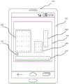
As shown in fig. 1, a user may first determine a target picture 103 on a page 102 displayed by a computing device 101.
As shown in fig. 2, the computing device 101 detects an object displayed in the target picture 103 determined by the user to obtain range information of a display range of the object. For example, by detecting the "person" object, the "article" object, and the "text" object in the target picture 103, the range information 104 of the "person" object, the range information 105 of the "article" object, and the range information 106 of the "text" object are obtained.
As shown in fig. 3, the computing device 101 constructs a "person" score map 107, an "article" score map 108, and a "letter" score map 109 from the above-described range information 104 of the "person" object, range information 105 of the "article" object, and range information 106 of the "letter" object. The size of the "person" score map 107 matches the display range of the "person" object, and similarly, the size of the "article" score map 108 matches the display range of the "article" object. The size of the "letter" score map 109 is adapted to the display range of the "letter" object. Further, the numerical values of the display range of the "person" object, the display range of the "article" object, and the "text" object in the display range of the score map may be "1". And the numerical value at a position outside the display range of the "person" object, the display range of the "article" object, and the display range of the "letter" object may be "0". As an example, the number of the above-described numerical values may be the same as the number of pixels in the display range of the object.
As shown in fig. 4, computing device 101 may generate a horizontal directional position vector 110. As an example, an "item" object may be cut.
The computing device 101 may determine the sum of the values in the "persona" score map 107, the "item" score map 108, and the "literal" score map 109 described above. Referring to fig. 4, the sum of the values is "30", "9" and "5", respectively. The numerical value is highest in the display range of the character object, and the character object is most important to be characterized. Therefore, the display range of the "person" object is generally within the clipping section. Since the "article" object can be cut, the element value of the element in the directional position vector corresponding to the display range of the "article" object is "0". The "text" object cannot be cut, and the element value of the element in the direction position vector corresponding to the display range of the "text" object is "1". Thus, the directional position vector may be [1,1,1,1,1,1,0,0,0,0,0,0,1,0 ]. Finally, as shown in fig. 5, the clipping region 111 may be a determined clipping region.
It is to be understood that the computing device 101 of the method for processing a picture may be a terminal device, a server, a device formed by integrating the terminal device and the server through a network, or various software. By way of example, computing device 101 may be a variety of electronic devices having information processing capabilities, including but not limited to smartphones, tablets, electronic book readers, laptop and desktop computers, and the like. When the execution subject is software, the execution subject can be installed in the electronic device enumerated above. It may be implemented as a plurality of software or software modules, for example, for providing distributed services, or as a single software or software module. The present invention is not particularly limited herein.
It should be understood that the number of computing devices in fig. 1 is merely illustrative. There may be any number of computing devices, as desired for an implementation.
With continued reference to fig. 6, a flow 600 of some embodiments of a picture processing method according to the present disclosure is shown. The picture processing method comprises the following steps:
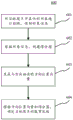
in step 601, an object displayed in the target picture is detected, and object information is obtained.
In some embodiments, an execution subject of the picture processing method (e.g., the computing device 101 shown in fig. 1) may detect an object displayed in the target picture selected by the user through a deep learning detection method, resulting in object information. The execution subject can also detect the object displayed in the target picture selected by the user through the deep learning image segmentation network to obtain object information. The deep learning detection method may include, but is not limited to, at least one of the following: SSD algorithm (Single Shot MultiBox Detector, target detection algorithm), R-CNN algorithm (Region-Convolutional Neural Networks, target detection algorithm), fastR-CNN algorithm (Fast Region-Convolutional Neural Networks, target detection algorithm), SPP-NET algorithm (Spatial Pyramid Pooling Network, target detection algorithm), yolo algorithm (You Only Look Once, target detection algorithm), FPN algorithm (Feature Pyramid Networks, target detection algorithm), DCN algorithm (Deformable ConvNets, variable convolution algorithm), retinaNet target detection algorithm. The deep-learning image segmentation network described above may include, but is not limited to, at least one of: FCN network (Fully Convolutional Networks, full convolution network), segNet network (Semantic Segmentation Network, image semantic segmentation network), deep lab semantic segmentation network, PSPNet network (Pyramid Scene Parsing Network, semantic segmentation network), mask-RCNN network (Mask-Region-CNN, image instance segmentation network).
Specifically, the object information may include range information for characterizing a display range of the object. It should be noted that, the target picture may be a picture specified by the user or determined by default settings of the terminal. The target picture may be a picture selected by the user from the local or may be a picture downloaded from the network.
Step 602, constructing a score graph according to the object information.
In some embodiments, the execution subject may construct a score map of the same size as the target picture. Specifically, the positions of the numerical values in the score map may correspond to the positions of the pixel points in the target picture one by one. In this way, the number of pixels included in the width direction or the height direction of the target picture corresponds to the number of values in the score map.
Further, the numerical value at the corresponding position of the display range of the object in the above score chart may be different from the numerical value at a position outside the display range of the object. As described with reference to fig. 3, as shown in fig. 3, the numerical value at the corresponding position of the display range of the "person" object, the display range of the "article" object, and the display range of the "letter" object in the score map may be "1". And the numerical value at a position outside the display range of the "person" object, the display range of the "article" object, and the display range of the "letter" object in the score map may be "0". When there is overlap of the objects in the display range in the score map, the numerical value at the corresponding position in the display range in the score map may be "2". I.e. the sum of the values at the corresponding positions of the overlapping display ranges. Note that the corresponding position may be a pixel position within the display range.
Further, the execution body may construct a plurality of object score maps using values at corresponding positions of the display ranges of the different objects. As an example, this is explained in connection with fig. 3. As shown in fig. 3, the target picture includes a display range of a "person" object, a display range of an "article" object, and a display range of a "text" object. The execution subject constructs the "person" score map 107 using the numerical values included in the display range of the "person" object. The execution body constructs the "item" score map 108 using the numerical values included in the display range of the "item" object. The execution subject constructs the "letter" score map 109 using the numerical values included in the display range of the "letter" object. The size of the "person" score map 107 is adapted to the display range of the "person" object, and similarly, the size of the "article" score map 108 is adapted to the display range of the "article" object. The size of the "letter" score map 109 is adapted to the display range of the "letter" object.
Optionally, the object information may further include object category information. The object category information may indicate categories of the "person" object, the "object, and the" text "object. Further, different values may be set at positions corresponding to the display ranges of the different category objects according to the object category information. As an example, the execution subject may set a numerical value at a corresponding position of the display range of the "person" object of the "person category", for example, set the above numerical value to "100". The corresponding position may be a pixel position within the display range. The numerical value at the corresponding position of the display range of the "text" object of the "text category" is set, and for example, the numerical value may be "10". The numerical value at the corresponding position of the display range of the "item" object of the "item category" is set, and for example, the numerical value may be "20". The value at the corresponding position outside the object display range may be "0". The execution subject may default the numerical values at the corresponding positions of the display ranges of the "person" object, the "article" object, and the "text" object, or may set the numerical values by the user. Specifically, the numerical value set by the user described above can be acquired by detecting an input operation by the user on the display screen.
Step 603, generating a direction position vector associated with the direction.
In some embodiments, the executing entity may generate the directional position vector with the same width as the target picture, for example, in a horizontal direction or a vertical direction. The above-described directional position vector is used to characterize whether an object can be cropped. Optionally, the number of elements of the direction position vector is equal to the number of pixels of the target picture in the above direction. The element value of the element of the direction position vector is set according to whether or not an object exists in a direction perpendicular to the above direction from the pixel point corresponding to the element in the target picture or whether or not the object can be cut. As an example, if there is no object in a direction perpendicular to the direction from a pixel point corresponding to an element in the target picture, the element value of the element of the direction position vector may be "0". If an object is present, the element value of the element of the directional position vector may be "1".
Further, if an object existing in a direction perpendicular to the above direction from a pixel point corresponding to an element in the target picture can be clipped, the element value of the element of the direction position vector may also be "0". Whether the object can be cut or not may be preset by the user, may be acquired by the execution subject through an input operation performed by the user on the display screen, or may be set by the execution subject by default. Further, the element value corresponding to the junction of different objects can be set to "0".
Step 604, determining a clipping region of the target picture according to the direction position vector and the score map.
In some embodiments, the execution subject may sum values at corresponding positions of the display range of different objects. The sum of the above values characterizes the importance of the object. The clipping region should generally include a display range of the object characterized by the sum of the values. As an example, the following is explained in connection with fig. 4. The sum of the values of the display ranges of the "person" object is "30", the sum of the values of the display ranges of the "article" object is "9", and the sum of the values of the display ranges of the "letter" object is "5". By comparing the sum of the values, it can be determined that the importance of the "person" object is highest, and therefore, the clipping region should include the display range of the "person" object.
The clipping region may then be further adjusted based on the directional position vector, for example, such that edges of the clipping region may pass over objects that can be clipped. As an example, this is explained in connection with fig. 4. As shown in fig. 4, the element value of the element of the directional position vector corresponding to the "article" object is "0". The characterization "item" object may be cropped. The element value of the element of the direction position vector corresponding to the "text" object is "1". The token "literal" object cannot be cropped. As an example, the clipping region may be from the left boundary of the display range of the "character" object to the left boundary of the display range of the "text" object.
In some alternative implementations of some embodiments, a direction score vector may also be generated that is related to the direction. The direction may be the same direction as the direction position vector. The above direction may be a horizontal direction or a vertical direction. The execution subject may sum in the score map of the target picture in the horizontal direction or the vertical direction to generate a direction score vector related to the direction. Specifically, the number of elements of the direction score vector is equal to the number of pixels in the direction in the clipping section. The element values of the elements of the direction score vector are generated by summing up the element values in a direction perpendicular to the direction from the position corresponding to the element in the score map.
As an example, the direction may be a horizontal direction, and then a direction perpendicular to the horizontal direction is a vertical direction, as described with reference to fig. 4. Taking the element 112 of the direction score vector as an example in connection with fig. 4, the element value of the element is determined by summing the values in the score map in the vertical direction from the position of the element 112. The element value of the element 112 of the direction score vector is 5. The number of pixels included in the display range of the "person" object in the horizontal direction is 6, and then the number of elements of the direction score vector corresponding to the display range of the "person" object is equal to 6. Taking the example that the cropping interval is equal to the complete target picture, the direction score vector may be [5,5,5,5,5,5,0,0,3,3,3,0,5,0].
Further, the first clipping position and the second clipping position may be determined according to a sum of element values of elements of the direction score vector included in a direction position vector, a first clipping position of a target picture in the direction, and a second clipping position. Further, a cropping area of the target picture is determined according to the first cropping position and the second cropping position. As shown in fig. 4, in the direction position vector [1,1,1,1,1,1,0,0,0,0,0,0,1,0 ], the element value of the element of the direction position vector corresponding to the "article" display range is "0". The representation "item" object may be cropped. As an example, in the case where the clipping width is set to a predetermined number (e.g., 9) of pixels, it may be determined that the width of the clipping region may include the width of the full display range of the "person" object and the width of the partial display range of the "article" object. To ensure that the sum of the values included in the clipping region is maximized.
According to the picture processing method disclosed by some embodiments of the present disclosure, object information can be obtained by detecting an object displayed in a target picture, where the object information may include range information. Then, a score map is constructed based on the object information. Next, a direction position vector associated with the direction is generated. And finally, determining a clipping region of the target picture according to the direction position vector and the score map. Specifically, the importance degree of each displayed object in the target picture can be represented by the score map. Further, by the above-described directional position vector, it can be determined that the object in the target picture can be cut out. Therefore, according to the direction position vector and the clipping region determined by the importance degree, not only is the importance degree of the object reflected by the clipped result picture, but also whether the display range of the object can be clipped can be distinguished, and the pertinence of the clipping region is improved.
With further reference to fig. 7, a flow 700 of further embodiments of a picture processing method is shown. The process 700 of the picture processing method includes the following steps:
in step 701, an object displayed in the target picture is detected, and object information is obtained.
Step 702, constructing a score graph according to the object information.
In step 703, a direction position vector associated with the direction is generated.
Step 704, determining a clipping region of the target picture according to the direction position vector and the score map.
In some embodiments, the specific implementation of steps 701-704 and the technical effects thereof may refer to steps 601-604 in those embodiments corresponding to fig. 6, which are not described herein.
Step 705, adjusting the clipping region according to the picture clipping information.
In some embodiments, the above-described picture cropping information may include a cropping width. The clipping region determined in step 704 is adjusted according to the clipping width. As an example, when the width of the clipping region is larger than the clipping width, the width of the clipping region is adjusted by the direction position vector. When some objects cannot be cut, it may occur that the width of the adjusted cut area is still greater than the above-mentioned cut width. At this time, the reduced picture region may be adapted to the clipping width by performing reduction processing on the picture region corresponding to the original clipping region.
Optionally, when the width of the adjusted clipping region is still greater than the clipping width, the clipping region may be adjusted by:
first, each pixel is given weight according to the numerical value of the score map.
Pixels with high values are weighted higher than pixels with low values. Next, a target width is set, which is the same as the above-described clipping width.
And secondly, adjusting the clipping region according to the weight.
The pixel deformation amount with high weight is smaller, the pixel deformation amount with low weight is larger, and the width of the deformed clipping region is consistent with the clipping width.
As an example, the width of the clipping region may include 10 pixel points. The clipping width includes 7 pixels. Wherein, the value corresponding to 8 pixel points in the 10 pixel points is 1. The value corresponding to the 2 pixel points is 0. The weight of 8 pixels may be set to 0.8,2 pixels and 0.2. And adjusting the pixel points according to the weights, so that the width of the adjusted clipping region is consistent with the clipping width.
Therefore, for the region with high representation importance, the deformation is smaller, and the processing mode for determining the shape variable according to the importance ensures the picture quality of the object display range in the clipping region.
In alternative implementations of some embodiments, the above clipping regions may also be adjusted by:
and a first step of generating a connection line of the pixel points according to the numerical value corresponding to each pixel point in the clipping region.
Wherein, the number of the pixel points in the display range of the object in the score graph is higher than the number of the pixel points outside the display range of the object. Specifically, the description is given with reference to fig. 8. Fig. 8 is a schematic diagram of an application scenario of some embodiments of adjusting clipping regions according to the present disclosure. As shown in fig. 8, the value of the pixel in the display range of the object may be "1", and the value of the pixel outside the display range of the object may be "0". The connection line of the pixel points may be a connection line that starts from the uppermost pixel point and connects the pixel points of the next layer adjacent to the pixel point, thereby generating a plurality of pixel points.
And secondly, determining the sum of the values of the pixel points through which the connection line passes as the connection line value of the connection line.
Specifically, the description is given with reference to fig. 8. As shown in fig. 8, taking the connection 801 of the rightmost pixel point as an example, the sum of the values of the pixel points is "3", and "3" is determined as the connection value of the pixel segment connection 801, as shown by reference numeral 802.
And thirdly, deleting the connecting lines with the connecting line values meeting preset conditions, and adjusting the cutting area.
Specifically, the predetermined condition may be when the value of the pixel point connection line is within a predetermined value range. The predetermined range of values may be set by a technician or may be set by a subject default. In this way, the clipping region is adjusted by deleting the connection line meeting the preset condition, so as to meet the clipping width.
In this way, the cutting interval can be adjusted in a targeted manner by deleting the connection line with the connection line value meeting the preset condition. The adjustment made for the display range of low characterization importance preserves the picture quality for the display range of high characterization importance.
In the picture processing method disclosed in some embodiments of the present disclosure, first, by detecting an object displayed in a target picture, object information can be obtained, where the object information may include range information. Then, a score map is constructed based on the object information. Next, a direction position vector associated with the direction is generated. And finally, determining a clipping region of the target picture according to the direction position vector and the score map. Specifically, the importance degree of each displayed object in the target picture can be represented by the score map. Further, by the above-described directional position vector, it can be determined that the object in the target picture can be cut out. Therefore, according to the direction position vector and the clipping region determined by the importance degree, not only is the importance degree of the object reflected by the clipped result picture, but also whether the display range of the object is within the range of the clipping region can be distinguished, and the pertinence of the clipping region is improved. In addition, the clipping region is further adjusted according to clipping information, so that objects with high clipping importance can be effectively avoided, clipping pertinence is improved, and user experience is improved.
With further reference to fig. 9, as an implementation of the method shown in the above figures, the present disclosure provides some embodiments of a picture processing apparatus, which correspond to those method embodiments shown in fig. 6, and which are particularly applicable in various electronic devices.
As shown in fig. 9, a picture processing apparatus 900 of some embodiments includes: a detection unit 901, a construction unit 902, a first generation unit 903 and a determination unit 904. The detecting unit 901 is configured to detect an object displayed in a target picture to obtain object information, where the object information includes range information for representing a display range of the object; the construction unit 902 is configured to construct a score map based on the above range information; the first generation unit 903 is configured to generate a direction position vector related to a direction; the determination unit 904 is configured to determine a clipping region of the target picture according to the score map.
In an alternative implementation of some embodiments, the picture processing apparatus 900 further includes: and an adjustment unit configured to adjust the clipping region according to the picture clipping information.
In an alternative implementation of some embodiments, the picture processing apparatus 900 further includes: and a second generation unit configured to generate a direction score vector related to a direction, the direction being a first direction or a second direction perpendicular to the first direction, wherein the number of elements of the direction score vector is equal to the number of pixels of the target picture in the direction, and element values of the elements of the direction score vector are generated by summing up in a direction perpendicular to the direction from a position corresponding to the elements in the score map.
In an alternative implementation of some embodiments, the determining unit 904 is further configured to: determining a first clipping position and a second clipping position of the target picture according to the sum of element values of elements of the direction score vector included in the direction position vector and the first clipping position and the second clipping position in the direction; and determining a clipping region of the target picture according to the first clipping position and the second clipping position.
In an alternative implementation of some embodiments, the adjustment unit is further configured to: generating a connection line of the pixel points according to the value corresponding to each pixel point in the clipping region, wherein the value of the pixel point in the display range of the object in the score graph is higher than the value of the pixel point outside the display range of the object; determining the sum of the values of the pixel points through which the connection line passes as the connection line value of the connection line; and deleting the connecting line with the connecting line value meeting the preset condition, and adjusting the cutting area.
In an alternative implementation manner of some embodiments, the number of elements of the direction position vector is equal to the number of pixels of the target picture in the direction, and the element value of the element of the direction position vector is set according to whether an object exists in a direction perpendicular to the direction or whether the object can be cropped starting from a pixel corresponding to the element in the target picture.
In some embodiments, the specific implementation of the detection unit 901, the construction unit 902, the first generation unit 903, and the determination unit 904 and the technical effects thereof included in the image processing apparatus 900 may refer to the corresponding embodiment of fig. 6, which is not described herein again.
Referring now to FIG. 10, a schematic diagram of a configuration of an electronic device (e.g., the computing device of FIG. 1) 1000 suitable for use in implementing some embodiments of the present disclosure is shown. The electronic devices in some embodiments of the present disclosure may include, but are not limited to, mobile terminals such as mobile phones, notebook computers, digital broadcast receivers, PDAs (personal digital assistants), PADs (tablet computers), PMPs (portable multimedia players), car terminals (e.g., car navigation terminals), and the like, as well as stationary terminals such as digital TVs, desktop computers, and the like. The electronic device shown in fig. 10 is merely an example, and should not impose any limitations on the functionality and scope of use of embodiments of the present disclosure.
As shown in fig. 10, the electronic device 1000 may include a processing means (e.g., a central processing unit, a graphics processor, etc.) 1001 that may perform various appropriate actions and processes according to a program stored in a Read Only Memory (ROM) 1002 or a program loaded from a storage means 1008 into a Random Access Memory (RAM) 1003. In the RAM 1003, various programs and data necessary for the operation of the electronic apparatus 1000 are also stored. The processing device 1001, the ROM 1002, and the RAM 1003 are connected to each other by a bus 1004. An input/output (I/O) interface 1005 is also connected to bus 1004.
In general, the following devices may be connected to the I/O interface 1005: input devices 1006 including, for example, a touch screen, touchpad, keyboard, mouse, camera, microphone, accelerometer, gyroscope, and the like; an output device 1007 including, for example, a Liquid Crystal Display (LCD), speaker, vibrator, etc.; and communication means 1009. The communication means 1009 may allow the electronic device 1000 to communicate wirelessly or by wire with other devices to exchange data. While fig. 10 shows an electronic device 1000 having various means, it is to be understood that not all of the illustrated means are required to be implemented or provided. More or fewer devices may be implemented or provided instead. Each block shown in fig. 10 may represent one device or a plurality of devices as needed.
In particular, according to some embodiments of the present disclosure, the processes described above with reference to flowcharts may be implemented as computer software programs. For example, some embodiments of the present disclosure include a computer program product comprising a computer program embodied on a computer readable medium, the computer program comprising program code for performing the method shown in the flow chart. In such embodiments, the computer program may be downloaded and installed from a network via communication device 1009, or from storage 1008, or from ROM 1002. The above-described functions defined in the methods of some embodiments of the present disclosure are performed when the computer program is executed by the processing device 1001.
It should be noted that, in some embodiments of the present disclosure, the computer readable medium may be a computer readable signal medium or a computer readable storage medium, or any combination of the two. The computer readable storage medium can be, for example, but not limited to, an electronic, magnetic, optical, electromagnetic, infrared, or semiconductor system, apparatus, or device, or a combination of any of the foregoing. More specific examples of the computer-readable storage medium may include, but are not limited to: an electrical connection having one or more wires, a portable computer diskette, a hard disk, a Random Access Memory (RAM), a read-only memory (ROM), an erasable programmable read-only memory (EPROM or flash memory), an optical fiber, a portable compact disc read-only memory (CD-ROM), an optical storage device, a magnetic storage device, or any suitable combination of the foregoing. In some embodiments of the present disclosure, a computer readable storage medium may be any tangible medium that can contain, or store a program for use by or in connection with an instruction execution system, apparatus, or device. In some embodiments of the present disclosure, however, the computer-readable signal medium may comprise a data signal propagated in baseband or as part of a carrier wave, with the computer-readable program code embodied therein. Such a propagated data signal may take any of a variety of forms, including, but not limited to, electro-magnetic, optical, or any suitable combination of the foregoing. A computer readable signal medium may also be any computer readable medium that is not a computer readable storage medium and that can communicate, propagate, or transport a program for use by or in connection with an instruction execution system, apparatus, or device. Program code embodied on a computer readable medium may be transmitted using any appropriate medium, including but not limited to: electrical wires, fiber optic cables, RF (radio frequency), and the like, or any suitable combination of the foregoing.
In some implementations, the clients, servers may communicate using any currently known or future developed network protocol, such as HTTP (HyperText Transfer Protocol ), and may be interconnected with any form or medium of digital data communication (e.g., a communication network). Examples of communication networks include a local area network ("LAN"), a wide area network ("WAN"), the internet (e.g., the internet), and peer-to-peer networks (e.g., ad hoc peer-to-peer networks), as well as any currently known or future developed networks.
The computer readable medium may be contained in the electronic device; or may exist alone without being incorporated into the electronic device. The computer readable medium carries one or more programs which, when executed by the electronic device, cause the electronic device to: detecting an object displayed in a target picture to obtain object information, wherein the object information comprises range information for representing the display range of the object; constructing a score map according to the range information, wherein the numerical value at the corresponding position of the display range of the object in the score map is different from the numerical value at the position outside the display range of the object; generating a direction position vector associated with the direction; and determining a clipping region of the target picture according to the direction position vector and the score diagram.
Computer program code for carrying out operations for some embodiments of the present disclosure may be written in one or more programming languages, including an object oriented programming language such as Java, smalltalk, C ++ and conventional procedural programming languages, such as the "C" programming language or similar programming languages. The program code may execute entirely on the user's computer, partly on the user's computer, as a stand-alone software package, partly on the user's computer and partly on a remote computer or entirely on the remote computer or server. In the case of a remote computer, the remote computer may be connected to the user's computer through any kind of network, including a Local Area Network (LAN) or a Wide Area Network (WAN), or may be connected to an external computer (for example, through the Internet using an Internet service provider).
The flowcharts and block diagrams in the figures illustrate the architecture, functionality, and operation of possible implementations of systems, methods and computer program products according to various embodiments of the present disclosure. In this regard, each block in the flowchart or block diagrams may represent a module, segment, or portion of code, which comprises one or more executable instructions for implementing the specified logical function(s). It should also be noted that, in some alternative implementations, the functions noted in the block may occur out of the order noted in the figures. For example, two blocks shown in succession may, in fact, be executed substantially concurrently, or the blocks may sometimes be executed in the reverse order, depending upon the functionality involved. It will also be noted that each block of the block diagrams and/or flowchart illustration, and combinations of blocks in the block diagrams and/or flowchart illustration, can be implemented by special purpose hardware-based systems which perform the specified functions or acts, or combinations of special purpose hardware and computer instructions.
The units described in some embodiments of the present disclosure may be implemented by means of software, or may be implemented by means of hardware. The described units may also be provided in a processor, for example, described as: a processor includes a detection unit, a construction unit, a first generation unit, and a determination unit. The names of these units do not limit the unit itself in some cases, and for example, the detection unit may also be described as "a unit that detects an object displayed in a target picture to obtain object information".
The functions described above herein may be performed, at least in part, by one or more hardware logic components. For example, without limitation, exemplary types of hardware logic components that may be used include: a Field Programmable Gate Array (FPGA), an Application Specific Integrated Circuit (ASIC), an Application Specific Standard Product (ASSP), a system on a chip (SOC), a Complex Programmable Logic Device (CPLD), and the like.
According to one or more embodiments of the present disclosure, there is provided a picture processing method including: detecting an object displayed in a target picture to obtain object information, wherein the object information comprises range information for representing the display range of the object; constructing a score map according to the range information, wherein the numerical value at the corresponding position of the display range of the object in the score map is different from the numerical value at the position outside the display range of the object; generating a direction position vector associated with the direction; and determining a clipping region of the target picture according to the direction position vector and the score diagram.
According to one or more embodiments of the present disclosure, the method further comprises: and adjusting the clipping region according to the picture clipping information.
According to one or more embodiments of the present disclosure, the method further comprises: and generating a direction score vector related to the direction, wherein the direction is a first direction or a second direction perpendicular to the first direction, the number of elements of the direction score vector is equal to the number of pixels of the target picture in the direction, and the element values of the elements of the direction score vector are generated by summing up along the direction perpendicular to the direction from the position corresponding to the elements in the score map.
According to one or more embodiments of the present disclosure, determining a cropping area of the target picture according to the score map includes: determining a first clipping position and a second clipping position of the target picture according to the sum of element values of elements of the direction score vector included in the direction position vector and the first clipping position and the second clipping position in the direction; and determining a clipping region of the target picture according to the first clipping position and the second clipping position.
According to one or more embodiments of the present disclosure, adjusting the cropping area according to the picture cropping information includes: generating a connection line of the pixel points according to the value corresponding to each pixel point in the clipping region, wherein the value of the pixel point in the display range of the object in the score graph is higher than the value of the pixel point outside the display range of the object; determining the sum of the values of the pixel points through which the connection line passes as the connection line value of the connection line; and deleting the connecting line with the connecting line value meeting the preset condition, and adjusting the cutting area.
According to one or more embodiments of the present disclosure, the number of elements of the direction position vector is equal to the number of pixels of the target picture in the direction, and the element values of the elements of the direction position vector are set according to whether an object exists in a direction perpendicular to the direction from the pixels corresponding to the elements in the target picture or whether the object can be cropped.
According to one or more embodiments of the present disclosure, there is provided a picture processing apparatus including: the detection unit 901 is configured to detect an object displayed in a target picture, and obtain object information, where the object information includes range information for characterizing a display range of the object; the construction unit 902 is configured to construct a score map based on the above range information; the first generation unit 903 is configured to generate a direction position vector related to a direction; the determination unit 904 is configured to determine a clipping region of the target picture according to the score map.
According to one or more embodiments of the present disclosure, the picture processing apparatus further includes: and an adjustment unit configured to adjust the clipping region according to the picture clipping information.
According to one or more embodiments of the present disclosure, the picture processing apparatus further includes: and a second generation unit configured to generate a direction score vector related to a direction, the direction being a first direction or a second direction perpendicular to the first direction, wherein the number of elements of the direction score vector is equal to the number of pixels of the target picture in the direction, and element values of the elements of the direction score vector are generated by summing up in a direction perpendicular to the direction from a position corresponding to the elements in the score map.
According to one or more embodiments of the present disclosure, the determining unit in the picture processing apparatus is further configured to: determining a first clipping position and a second clipping position of the target picture according to the sum of element values of elements of the direction score vector included in the direction position vector and the first clipping position and the second clipping position in the direction; and determining a clipping region of the target picture according to the first clipping position and the second clipping position.
According to one or more embodiments of the present disclosure, the adjusting unit in the picture processing apparatus is further configured to: generating a connection line of the pixel points according to the value corresponding to each pixel point in the clipping region, wherein the value of the pixel point in the display range of the object in the score graph is higher than the value of the pixel point outside the display range of the object; determining the sum of the values of the pixel points through which the connection line passes as the connection line value of the connection line; and deleting the connecting line with the connecting line value meeting the preset condition, and adjusting the cutting area.
According to one or more embodiments of the present disclosure, the number of elements of the direction position vector is equal to the number of pixels of the target picture in the direction, and the element values of the elements of the direction position vector are set according to whether an object exists in a direction perpendicular to the direction from the pixels corresponding to the elements in the target picture or whether the object can be cropped.
The foregoing description is only of the preferred embodiments of the present disclosure and description of the principles of the technology being employed. It will be appreciated by those skilled in the art that the scope of the invention in the embodiments of the present disclosure is not limited to the specific combination of the above technical features, but encompasses other technical features formed by any combination of the above technical features or their equivalents without departing from the spirit of the invention. Such as the above-described features, are mutually substituted with (but not limited to) the features having similar functions disclosed in the embodiments of the present disclosure.