CN111447860A - retail merchandise tray - Google Patents
retail merchandise tray Download PDFInfo
- Publication number
- CN111447860A CN111447860A CN201880077840.4A CN201880077840A CN111447860A CN 111447860 A CN111447860 A CN 111447860A CN 201880077840 A CN201880077840 A CN 201880077840A CN 111447860 A CN111447860 A CN 111447860A
- Authority
- CN
- China
- Prior art keywords
- pair
- spacers
- mounting
- retail merchandise
- load bearing
- Prior art date
- Legal status (The legal status is an assumption and is not a legal conclusion. Google has not performed a legal analysis and makes no representation as to the accuracy of the status listed.)
- Granted
Links
Images


Classifications
-
- A—HUMAN NECESSITIES
- A47—FURNITURE; DOMESTIC ARTICLES OR APPLIANCES; COFFEE MILLS; SPICE MILLS; SUCTION CLEANERS IN GENERAL
- A47F—SPECIAL FURNITURE, FITTINGS, OR ACCESSORIES FOR SHOPS, STOREHOUSES, BARS, RESTAURANTS OR THE LIKE; PAYING COUNTERS
- A47F1/00—Racks for dispensing merchandise; Containers for dispensing merchandise
- A47F1/04—Racks or containers with arrangements for dispensing articles, e.g. by means of gravity or springs
- A47F1/12—Racks or containers with arrangements for dispensing articles, e.g. by means of gravity or springs dispensing from the side of an approximately horizontal stack
- A47F1/125—Racks or containers with arrangements for dispensing articles, e.g. by means of gravity or springs dispensing from the side of an approximately horizontal stack with an article-pushing device
- A47F1/126—Racks or containers with arrangements for dispensing articles, e.g. by means of gravity or springs dispensing from the side of an approximately horizontal stack with an article-pushing device the pushing device being urged by spring means
-
- A—HUMAN NECESSITIES
- A47—FURNITURE; DOMESTIC ARTICLES OR APPLIANCES; COFFEE MILLS; SPICE MILLS; SUCTION CLEANERS IN GENERAL
- A47B—TABLES; DESKS; OFFICE FURNITURE; CABINETS; DRAWERS; GENERAL DETAILS OF FURNITURE
- A47B57/00—Cabinets, racks or shelf units, characterised by features for adjusting shelves or partitions
- A47B57/58—Cabinets, racks or shelf units, characterised by features for adjusting shelves or partitions with means for adjusting partitions horizontally
-
- A—HUMAN NECESSITIES
- A47—FURNITURE; DOMESTIC ARTICLES OR APPLIANCES; COFFEE MILLS; SPICE MILLS; SUCTION CLEANERS IN GENERAL
- A47F—SPECIAL FURNITURE, FITTINGS, OR ACCESSORIES FOR SHOPS, STOREHOUSES, BARS, RESTAURANTS OR THE LIKE; PAYING COUNTERS
- A47F5/00—Show stands, hangers, or shelves characterised by their constructional features
- A47F5/0018—Display racks with shelves or receptables
- A47F5/0025—Display racks with shelves or receptables having separate display containers or trays on shelves or on racks
-
- A—HUMAN NECESSITIES
- A47—FURNITURE; DOMESTIC ARTICLES OR APPLIANCES; COFFEE MILLS; SPICE MILLS; SUCTION CLEANERS IN GENERAL
- A47F—SPECIAL FURNITURE, FITTINGS, OR ACCESSORIES FOR SHOPS, STOREHOUSES, BARS, RESTAURANTS OR THE LIKE; PAYING COUNTERS
- A47F5/00—Show stands, hangers, or shelves characterised by their constructional features
- A47F5/0043—Show shelves
- A47F5/005—Partitions therefore
-
- A—HUMAN NECESSITIES
- A47—FURNITURE; DOMESTIC ARTICLES OR APPLIANCES; COFFEE MILLS; SPICE MILLS; SUCTION CLEANERS IN GENERAL
- A47F—SPECIAL FURNITURE, FITTINGS, OR ACCESSORIES FOR SHOPS, STOREHOUSES, BARS, RESTAURANTS OR THE LIKE; PAYING COUNTERS
- A47F1/00—Racks for dispensing merchandise; Containers for dispensing merchandise
- A47F1/04—Racks or containers with arrangements for dispensing articles, e.g. by means of gravity or springs
- A47F1/12—Racks or containers with arrangements for dispensing articles, e.g. by means of gravity or springs dispensing from the side of an approximately horizontal stack
Landscapes
- Freezers Or Refrigerated Showcases (AREA)
- Display Racks (AREA)
- Vending Machines For Individual Products (AREA)
- Details Of Rigid Or Semi-Rigid Containers (AREA)
Abstract
Description
技术领域technical field
本发明总体涉及零售商品展示装置,且更具体地,涉及被用来偏压零售商品向前的自饰面(self-facing)零售商品展示装置。The present invention relates generally to retail merchandise displays and, more particularly, to self-facing retail merchandise displays used to bias retail merchandise forward.
背景技术Background technique
自饰面零售商品展示装置是本领域普遍已知的。曾经这样的展示装置是推压器系统。常规推压器系统包含沿相应细长轨道座置的一个或多个推压器桨或推压器本体。弹簧连接在推压器本体与轨道的前导边缘之间。弹簧用来偏压推压器本体沿着轨道向前朝向轨道的前导边缘。Self-facing retail merchandise displays are generally known in the art. Once such a display device was the pusher system. Conventional pusher systems include one or more pusher paddles or pusher bodies seated along respective elongated rails. A spring is connected between the pusher body and the leading edge of the track. A spring is used to bias the pusher body forward along the track towards the leading edge of the track.
使用者可缩回推压器本体使之离开轨道的前导边缘并在轨道的顶部上且在轨道的前导边缘与推压器本体之间以成一直线排的方式定位零售商品项。由弹簧提供且施加在推压器本体上的偏压力服务于偏压零售商品的直线排向前以最终“前饰面”商品。The user can retract the pusher body away from the leading edge of the track and position the retail item of merchandise in an in-line row on top of the track and between the leading edge of the track and the pusher body. The biasing force provided by the spring and applied to the pusher body serves to bias the straight row of retail merchandise forward to ultimately "front finish" merchandise.
也就是,当消费者从商品的直线排中移除最前沿的商品项时,推压器本体将被弹簧向前拖拉,以使商品排向前转位(index),使得排中的下一商品项以美观的方式邻近轨道的前导边缘定位。这样的自动前饰面消除了零售店雇员手动进行商品饰面的必要,且因此最终降低了零售商的人工成本。That is, when the consumer removes the leading item of merchandise from the linear row of merchandise, the pusher body will be pulled forward by the spring to index the row of merchandise forward so that the next Merchandise items are positioned adjacent the leading edge of the track in an aesthetically pleasing manner. Such automatic front facing eliminates the need for retail store employees to manually finish merchandise, and thus ultimately reduces labor costs for the retailer.
上述推压器系统已被用于各种零售展示环境中。一个示例是零售搁架。通常,多个推压器本体及它们对应的轨道沿着搁架以并排方式布置。每个推压器本体及其对应的轨道通过分隔物分开以维持多个从搁架的前部延伸到后部的、大体顺直的商品排。在用于销售卫生物品(比如体香剂,作为一个示例)的许多零售店中可找到这种熟悉的配置。The pusher systems described above have been used in a variety of retail display environments. An example is retail shelving. Typically, multiple pusher bodies and their corresponding tracks are arranged in a side-by-side fashion along the shelf. Each pusher body and its corresponding track are separated by dividers to maintain a plurality of generally straight rows of merchandise extending from the front to the rear of the shelf. This familiar arrangement can be found in many retail stores for the sale of hygiene articles such as deodorants, as an example.
在另一种配置中,推压器系统可具体化为独立的推压器托盘。这些托盘可包括这样的器具,所述器具用于将托盘安装成从另一结构(比如条杆)的悬臂延伸部。这些托盘也可直接置于零售搁架上。另外,这些托盘可包括侧隔障,所述侧隔障能够调节以从而适应不同宽度的商品。在美国专利号9,254,049、9,241,583、8,720,702处可容易看到这些托盘的示例,所述美国专利中每件的全部内容通过引用的方式并入到本文中。In another configuration, the pusher system may be embodied as a separate pusher tray. These trays may include means for mounting the tray as a cantilevered extension from another structure, such as a bar. These trays can also be placed directly on retail shelves. Additionally, these trays may include side barriers that can be adjusted to accommodate different widths of merchandise. Examples of these trays can be readily seen in US Pat. Nos. 9,254,049, 9,241,583, 8,720,702, each of which is incorporated herein by reference in its entirety.
本发明涉及在以上所描述的推压器系统方面的、更具体地以上所描述的推压器托盘方面的改进。本发明的这些及其它优点以及另外的发明特征将从对本文中所提供的发明的描述中显见。The present invention relates to improvements in the pusher systems described above, and more particularly with the pusher trays described above. These and other advantages and additional inventive features of the present invention will be apparent from the description of the invention provided herein.
发明内容SUMMARY OF THE INVENTION
在一个方面中,本发明提供一种零售商品托盘,该零售商品托盘包含容易安装的线支撑结构。根据该方面的零售商品托盘具有这样的优点:无需任何焊接过程来将线支撑结构附接到托盘的其余部分。根据该方面的实施例包括一对相对的负载支承构件,并包括安装到所述一对负载支承构件的前止挡部。零售商品托盘的该实施例还包括线支撑结构,所述线支撑结构具有相反的第一端和第二端。线支撑结构在第一端处可移除地附连到前止挡部且在第二端处可移除地附连到所述一对负载支承构件。零售商品托盘的该实施例还包括推压器,所述推压器安装到线支撑结构并可沿着线支撑结构朝向及远离前止挡部沿第一轴线移动。还包括至少一个分隔物组件,且所述至少一个分隔物组件可相对于所述一对相对的负载支承构件沿与第一轴线垂直的第二轴线移动。一对间隔件沿着第一轴线对齐并介于所述一对负载支承构件之间且置于线支撑框架下方。In one aspect, the present invention provides a retail merchandise tray that includes an easily installed wire support structure. The retail merchandise tray according to this aspect has the advantage that no welding process is required to attach the wire support structure to the rest of the tray. Embodiments according to this aspect include a pair of opposing load bearing members, and include a front stop mounted to the pair of load bearing members. This embodiment of the retail merchandise tray also includes a wire support structure having opposing first and second ends. A wire support structure is removably attached to the front stop at a first end and to the pair of load bearing members at a second end. This embodiment of the retail merchandise tray also includes a pusher mounted to the wire support structure and movable along the first axis toward and away from the front stop along the wire support structure. At least one divider assembly is also included, and the at least one divider assembly is movable relative to the pair of opposing load support members along a second axis perpendicular to the first axis. A pair of spacers are aligned along the first axis and are interposed between the pair of load bearing members and positioned below the wire support frame.
在根据该方面的实施例中,所述至少一个分隔物组件包括一对分隔物组件,所述一对分隔物组件可关于第二轴线移动并布置成使得所述一对负载支承构件介于所述一对分隔物组件之间。所述至少一个分隔物组件包括分隔物壁和一对线支撑。所述一对线支撑通过弹性连接可移除地附连到分隔物。In embodiments according to this aspect, the at least one divider assembly includes a pair of divider assemblies moveable about the second axis and arranged such that the pair of load bearing members are interposed between the pair of divider assemblies. between the pair of spacer assemblies. The at least one divider assembly includes a divider wall and a pair of wire supports. The pair of wire supports are removably attached to the divider by elastic connections.
在根据该方面的实施例中,分隔物壁包括直立部,直立部具有相反两侧。凸缘从所述相反两侧中的至少一侧垂直于直立部延伸。至少一个分隔物组件包括挡板延伸部,所述挡板延伸部通过可滑动连接连接到至少一个凸缘。挡板延伸部通过可滑动连接被安装到所述一对间隔件中的每个使得,所述挡板延伸部能够相对于所述一对间隔件和相对于所述分隔物壁滑动。在挡板延伸部与至少一个凸缘之间的可滑动连接包括从凸缘向下悬伸(depend)的突部和在挡板延伸部中形成的接收突部的槽。在挡板延伸部与所述一对间隔件之间的可滑动连接包括在挡板延伸部中形成的一对夹具,而所述一对夹具中的一个夹具连接到所述一对间隔件中的一个间隔件且所述一对夹具中的另一夹具连接到所述一对间隔件中的另一间隔件。In an embodiment according to this aspect, the divider wall includes an upstanding portion having opposite sides. A flange extends perpendicular to the upright portion from at least one of the opposite sides. At least one divider assembly includes a baffle extension connected to at least one flange by a slidable connection. The baffle extension is mounted to each of the pair of spacers by a slidable connection such that the baffle extension is slidable relative to the pair of spacers and relative to the divider wall. The slidable connection between the baffle extension and the at least one flange includes a projection that depends downwardly from the flange and a slot formed in the baffle extension to receive the projection. The slidable connection between the baffle extension and the pair of spacers includes a pair of clips formed in the baffle extension, one clip of the pair of clips being connected to the pair of spacers one spacer of the pair and the other clamp of the pair of clamps is connected to the other spacer of the pair of spacers.
在根据该方面的实施例中,挡板连接到所述一对间隔件。挡板包括一对夹具,而所述一对夹具中的一个夹具连接到所述一对间隔件中的一个间隔件且所述一对夹具中的另一夹具连接到所述一对间隔件中的另一间隔件。In an embodiment according to this aspect, a baffle is connected to the pair of spacers. The baffle includes a pair of clips with one clip of the pair connected to one spacer of the pair of spacers and the other clip of the pair connected to the pair of spacers another spacer.
在根据该方面的实施例中,提供一种用于将零售商品托盘安装到搁架的搁架安装布置结构。所述搁架安装布置结构包括如下中的一者:安装板,所述安装板可移除地附连到所述一对间隔件中的一个。所述安装板具有延伸部,所述延伸部配置成延伸到搁架的孔口中以将托盘固定到搁架,或者安装轨,所述安装轨配置用于安装到零售搁架和至少一个安装突部,安装轨包括多个间隔开的齿,所述齿布置成在相邻的齿之间的空间中接收所述至少一个安装突部,所述至少一个安装突部在前止挡部上形成。In an embodiment according to this aspect, a shelf mounting arrangement for mounting a retail merchandise tray to a shelf is provided. The shelf mounting arrangement includes one of: a mounting plate removably attached to one of the pair of spacers. The mounting plate has an extension configured to extend into an aperture of the shelf to secure the tray to the shelf, or a mounting rail configured for mounting to a retail shelf and at least one mounting protrusion. the mounting rail includes a plurality of spaced teeth arranged to receive the at least one mounting tab in the space between adjacent teeth, the at least one mounting tab formed on the front stop .
在根据该方面的实施例中,前止挡部包括安装部和直立部。安装部是如下中的一种:与直立部一体形成为刚性的一件式部件,或者被形成为与直立部分开的部件、而在直立部与安装部之间形成铰链使得直立部可绕着铰链相对于安装部旋转。In an embodiment according to this aspect, the front stop portion includes a mounting portion and an upright portion. The mounting portion is one of a rigid one-piece component integrally formed with the upright portion, or formed as a separate component from the upright portion, with a hinge formed between the upright portion and the mounting portion so that the upright portion can wrap around The hinge rotates relative to the mounting portion.
在根据该方面的实施例中,线支撑结构包括侧向元件和从侧向元件延伸的至少一个纵向元件。侧向元件包括一对相反的端部,而键形成在所述相反的端部中的每一个附近。每个键布置成分别穿过在所述一对负载支承构件中的每一个中形成的键槽,使得所述一对负载支承构件介于在侧向构件的每个端部处形成的键之间。In embodiments according to this aspect, the wire support structure includes lateral elements and at least one longitudinal element extending from the lateral elements. The lateral elements include a pair of opposing ends, and a key is formed adjacent each of the opposing ends. Each key is arranged to pass through a keyway formed in each of the pair of load bearing members, respectively, such that the pair of load bearing members is interposed between the keys formed at each end of the lateral member .
在另一方面中,本发明提供一种零售商品托盘,该零售商品托盘采用分隔物组件,所述分隔物组件通过弹性连接组装。这具有避免关于分隔物组件的任何焊接的优点,并允许用于快速地更换分隔物组件的分隔物壁。根据该方面的实施例包括一对相对的负载支承构件,而前止挡部被安装到所述一对负载支承构件。零售商品托盘的该实施例还包括线支撑结构,所述线支撑结构包括侧向元件和从侧向元件延伸的至少一个纵向元件。所述至少一个纵向元件平行于所述一对负载支承构件延伸且介于所述一对负载支承构件之间。推压器安装到线支撑结构。推压器可沿着线支撑结构朝向及远离前止挡部沿第一轴线移动。零售商品托盘的该实施例还包括至少一个分隔物组件,所述至少一个分隔物组件可相对于所述一对相对的负载支承构件沿与第一轴线垂直的第二轴线移动。所述至少一个分隔物包括分隔物壁和一对线支撑,所述一对线支撑通过弹性连接可移除地附连到分隔物。一对间隔件沿着第一轴线对齐并介于所述一对负载支承构件之间且置于线支撑框架下方。所述一对间隔件接收所述至少一个分隔物的线支撑。In another aspect, the present invention provides a retail merchandise tray employing divider assemblies assembled by resilient connections. This has the advantage of avoiding any welding on the divider assembly and allows for quick replacement of the divider walls of the divider assembly. Embodiments according to this aspect include a pair of opposing load bearing members to which the front stop is mounted. This embodiment of the retail merchandise tray also includes a wire support structure including a lateral element and at least one longitudinal element extending from the lateral element. The at least one longitudinal element extends parallel to and between the pair of load bearing members. The pusher is mounted to the wire support structure. The pusher is movable along the first axis toward and away from the front stop along the wire support structure. This embodiment of the retail merchandise tray also includes at least one divider assembly movable relative to the pair of opposing load support members along a second axis perpendicular to the first axis. The at least one divider includes a divider wall and a pair of wire supports removably attached to the divider by elastic connections. A pair of spacers are aligned along the first axis and are interposed between the pair of load bearing members and positioned below the wire support frame. The pair of spacers receive a wire support of the at least one divider.
在根据该方面的实施例中,所述至少一个分隔物组件包括一对分隔物组件,所述一对分隔物组件可关于第二轴线移动并布置成使得所述一对负载支承构件介于所述一对分隔物组件之间。In embodiments according to this aspect, the at least one divider assembly includes a pair of divider assemblies moveable about the second axis and arranged such that the pair of load bearing members are interposed between the pair of divider assemblies. between the pair of spacer assemblies.
在根据该方面的实施例中,线支撑结构具有相反的第一端和第二端。线支撑结构在第一端处可移除地附连到前止挡部且在第二端处可移除地附连到所述一对负载支承构件。In embodiments according to this aspect, the wire support structure has opposite first and second ends. A wire support structure is removably attached to the front stop at a first end and to the pair of load bearing members at a second end.
在根据该方面的实施例中,分隔物壁包括直立部,直立部具有相反两侧。凸缘从所述相反两侧中的至少一侧垂直于直立部延伸。所述至少一个分隔物组件包括挡板延伸部,所述挡板延伸部通过可滑动连接连接到至少一个凸缘。挡板延伸部通过可滑动连接被安装到所述一对间隔件中的每个使得,挡板延伸部能够相对于所述一对间隔件和相对于所述分隔物壁滑动。在挡板延伸部与至少一个凸缘之间的可滑动连接包括从凸缘向下悬伸的突部和在挡板延伸部中形成的接收突部的槽。在挡板延伸部与所述一对间隔件之间的可滑动连接包括在挡板延伸部上形成的一对夹具,而所述一对夹具中的一个夹具连接到所述一对间隔件中的一个间隔件且所述一对夹具中的另一夹具连接到所述一对间隔件中的另一间隔件。In an embodiment according to this aspect, the divider wall includes an upstanding portion having opposite sides. A flange extends perpendicular to the upright portion from at least one of the opposite sides. The at least one divider assembly includes a baffle extension connected to at least one flange by a slidable connection. The baffle extension is mounted to each of the pair of spacers by a slidable connection such that the baffle extension can slide relative to the pair of spacers and relative to the divider wall. The slidable connection between the baffle extension and the at least one flange includes a tab depending downwardly from the flange and a slot formed in the baffle extension to receive the tab. The slidable connection between the baffle extension and the pair of spacers includes a pair of clips formed on the baffle extension, with one clip of the pair connected to the pair of spacers one spacer of the pair and the other clamp of the pair of clamps is connected to the other spacer of the pair of spacers.
在根据该方面的实施例中,挡板连接到所述一对间隔件。挡板包括一对夹具,而所述一对夹具中的一个夹具连接到所述一对间隔件中的一个间隔件且所述一对夹具中的另一夹具连接到所述一对间隔件中的另一间隔件。In an embodiment according to this aspect, a baffle is connected to the pair of spacers. The baffle includes a pair of clips with one clip of the pair connected to one spacer of the pair of spacers and the other clip of the pair connected to the pair of spacers another spacer.
在根据该方面的实施例中,提供一种用于将零售商品托盘安装到搁架的搁架安装布置结构。搁架安装布置结构包括如下中的一者:安装板,所述安装板可移除地附连到所述一对间隔件中的一个。安装板具有延伸部,所述延伸部配置成延伸到搁架的孔口中以将托盘固定到搁架,或者安装轨,所述安装轨配置用于安装到零售搁架和至少一个安装突部,所述安装轨包括多个间隔开的齿,所述齿布置成在相邻的齿之间的空间中接收所述至少一个安装突部,所述至少一个安装突部在前止挡部上形成。In an embodiment according to this aspect, a shelf mounting arrangement for mounting a retail merchandise tray to a shelf is provided. The shelf mounting arrangement includes one of: a mounting plate removably attached to one of the pair of spacers. the mounting plate has an extension configured to extend into an aperture of the shelf to secure the tray to the shelf, or a mounting rail configured for mounting to the retail shelf and at least one mounting tab, The mounting rail includes a plurality of spaced teeth arranged to receive the at least one mounting tab in the space between adjacent teeth, the at least one mounting tab formed on the front stop .
在根据该方面的实施例中,前止挡部包括安装部和直立部。安装部是如下中的一种:与直立部一体形成为刚性的一件式部件,或者被形成为与直立部分开的部件、而在直立部与安装部之间形成铰链使得直立部可绕着铰链相对于安装部旋转。In an embodiment according to this aspect, the front stop portion includes a mounting portion and an upright portion. The mounting portion is one of a rigid one-piece component integrally formed with the upright portion, or formed as a separate component from the upright portion, with a hinge formed between the upright portion and the mounting portion so that the upright portion can wrap around The hinge rotates relative to the mounting portion.
在根据该方面的实施例中,线支撑结构包括侧向元件和从侧向元件延伸的至少一个纵向元件。侧向元件包括一对相反的端部,而键形成在所述相反的端部中的每一个附近。每个键布置成分别穿过在所述一对负载支承构件中的每一个中形成的键槽,使得所述一对负载支承构件介于在侧向构件的每个端部处形成的键之间。In embodiments according to this aspect, the wire support structure includes lateral elements and at least one longitudinal element extending from the lateral elements. The lateral elements include a pair of opposing ends, and a key is formed adjacent each of the opposing ends. Each key is arranged to pass through a keyway formed in each of the pair of load bearing members, respectively, such that the pair of load bearing members is interposed between the keys formed at each end of the lateral member .
在仍另一方面中,本发明提供一种零售商品托盘,所述零售商品托盘有利地利用键连接布置结构,所述键连接布置结构用于安装线支撑结构。根据该方面的实施例包括一对相对的负载支承构件,而前止挡部被安装到所述一对负载支承构件。商品零售托盘的该实施例还包括线支撑结构,所述线支撑结构包括侧向元件和从侧向元件延伸的至少一个纵向元件。侧向元件包括一对相反的端部。键形成在所述相反的端部中的每一个附近。每个键布置成分别穿过在所述一对负载支承构件中的每一个中形成的键槽,使得所述一对负载支承构件介于在侧向构件的每个端部处形成的键之间。零售商品托盘的该实施例还包括推压器,所述推压器安装到线支撑结构。推压器可沿着线支撑结构朝向及远离前止挡部沿第一轴线移动。至少一个分隔物组件可相对于所述一对相对的负载支承构件沿与第一轴线垂直的第二轴线移动。一对间隔件沿着第一轴线对齐并介于所述一对负载支承构件之间且置于线支撑框架下方。In yet another aspect, the present invention provides a retail merchandise tray that advantageously utilizes a keyed connection arrangement for mounting a wire support structure. Embodiments according to this aspect include a pair of opposing load bearing members to which the front stop is mounted. This embodiment of the retail tray of merchandise also includes a wire support structure including a lateral element and at least one longitudinal element extending from the lateral element. The lateral elements include a pair of opposing ends. A key is formed near each of the opposite ends. Each key is arranged to pass through a keyway formed in each of the pair of load bearing members, respectively, such that the pair of load bearing members is interposed between the keys formed at each end of the lateral member . This embodiment of the retail merchandise tray also includes a pusher mounted to the wire support structure. The pusher is movable along the first axis toward and away from the front stop along the wire support structure. At least one divider assembly is movable relative to the pair of opposing load support members along a second axis perpendicular to the first axis. A pair of spacers are aligned along the first axis and are interposed between the pair of load bearing members and positioned below the wire support frame.
在根据该方面的实施例中,所述至少一个分隔物组件包括一对分隔物组件,所述一对分隔物组件可关于第二轴线移动且布置成使得所述一对负载支承构件介于所述一对分隔物组件之间。In embodiments according to this aspect, the at least one divider assembly includes a pair of divider assemblies movable about the second axis and arranged such that the pair of load bearing members are interposed between the pair of divider assemblies. between the pair of spacer assemblies.
在根据该方面的实施例中,线支撑结构具有相反的第一端和第二端。线支撑结构在第一端处可移除地附连到前止挡部且在第二端处可移除地附连到所述一对负载支承构件。In embodiments according to this aspect, the wire support structure has opposite first and second ends. A wire support structure is removably attached to the front stop at a first end and to the pair of load bearing members at a second end.
在根据该方面的实施例中,分隔物壁包括直立部,直立部具有相反两侧。凸缘从所述相反两侧中的至少一侧垂直于直立部延伸。至少一个分隔物组件包括挡板延伸部,挡板延伸部通过可滑动连接连接到至少一个凸缘。挡板延伸部通过可滑动连接被安装到所述一对间隔件中的每个使得,挡板延伸部能够相对于所述一对间隔件和相对于所述分隔物壁滑动。在挡板延伸部与至少一个凸缘之间的可滑动连接包括从凸缘向下悬伸的突部和在挡板延伸部中形成的接收突部的槽。在挡板延伸部与所述一对间隔件之间的可滑动连接包括在挡板延伸部上形成的一对夹具,而所述一对夹具中的一个夹具连接到所述一对间隔件中的一个间隔件且所述一对夹具中的另一夹具连接到所述一对间隔件中的另一间隔件。In an embodiment according to this aspect, the divider wall includes an upstanding portion having opposite sides. A flange extends perpendicular to the upright portion from at least one of the opposite sides. At least one divider assembly includes a baffle extension connected to the at least one flange by a slidable connection. The baffle extension is mounted to each of the pair of spacers by a slidable connection such that the baffle extension can slide relative to the pair of spacers and relative to the divider wall. The slidable connection between the baffle extension and the at least one flange includes a tab depending downwardly from the flange and a slot formed in the baffle extension to receive the tab. The slidable connection between the baffle extension and the pair of spacers includes a pair of clips formed on the baffle extension, with one clip of the pair connected to the pair of spacers one spacer of the pair and the other clamp of the pair of clamps is connected to the other spacer of the pair of spacers.
在根据该方面的实施例中,挡板连接到所述一对间隔件。挡板包括一对夹具,而所述一对夹具中的一个夹具连接到所述一对间隔件中的一个间隔件且所述一对夹具中的另一夹具连接到所述一对间隔件中的另一间隔件。In an embodiment according to this aspect, a baffle is connected to the pair of spacers. The baffle includes a pair of clips with one clip of the pair connected to one spacer of the pair of spacers and the other clip of the pair connected to the pair of spacers another spacer.
在根据该方面的实施例中,提供一种用于将零售商品托盘安装到搁架的搁架安装布置结构。搁架安装布置结构包括如下中的一者:安装板,所述安装板可移除地附连到所述一对间隔件中的一个。安装板具有延伸部,所述延伸部配置成延伸到搁架的孔口中以将托盘固定到搁架,或者安装轨,所述安装轨配置用于安装到零售搁架和至少一个安装突部,所述安装轨包括多个间隔开的齿,所述齿布置成在相邻的齿之间的空间中接收所述至少一个安装突部,所述至少一个安装突部在前止挡部上形成。In an embodiment according to this aspect, a shelf mounting arrangement for mounting a retail merchandise tray to a shelf is provided. The shelf mounting arrangement includes one of: a mounting plate removably attached to one of the pair of spacers. the mounting plate has an extension configured to extend into an aperture of the shelf to secure the tray to the shelf, or a mounting rail configured for mounting to the retail shelf and at least one mounting tab, The mounting rail includes a plurality of spaced teeth arranged to receive the at least one mounting tab in the space between adjacent teeth, the at least one mounting tab formed on the front stop .
在根据该方面的实施例中,前止挡部包括安装部和直立部。安装部是如下中的一种:与直立部一体形成为刚性的一件式部件,或者被形成为与直立部分开的部件、而在直立部与安装部之间形成铰链使得直立部可绕着铰链相对于安装部旋转。In an embodiment according to this aspect, the front stop portion includes a mounting portion and an upright portion. The mounting portion is one of a rigid one-piece component integrally formed with the upright portion, or formed as a separate component from the upright portion, with a hinge formed between the upright portion and the mounting portion so that the upright portion can wrap around The hinge rotates relative to the mounting portion.
在根据该方面的实施例中,所述至少一个分隔物组件包括分隔物壁和一对线支撑。所述一对线支撑通过弹性连接可移除地附连到分隔物。In embodiments according to this aspect, the at least one divider assembly includes a divider wall and a pair of wire supports. The pair of wire supports are removably attached to the divider by elastic connections.
当结合附图来理解时,从以下的详细描述中,本发明的其它方面、目的以及优点将变得更加显见。Other aspects, objects and advantages of the present invention will become more apparent from the following detailed description when read in conjunction with the accompanying drawings.
附图说明Description of drawings
包含在本说明书中且形成本说明书的一部分的附图图示出本发明的若干方面,并与描述一起用来说明本发明的原理。在附图中:The accompanying drawings incorporated in and forming a part of this specification illustrate several aspects of the invention and together with the description serve to explain the principles of the invention. In the attached image:
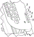
图1是根据本文中的教导的零售商品托盘的示例性实施例的立体图;1 is a perspective view of an exemplary embodiment of a retail merchandise tray in accordance with the teachings herein;
图2是图1的零售商品托盘的分解立体图;Figure 2 is an exploded perspective view of the retail merchandise tray of Figure 1;
图3是在间隔件的区域中截取的图1的零售商品托盘的截面;3 is a cross-section of the retail merchandise tray of FIG. 1 taken in the region of the spacer;
图4是图1的分隔物组件的局部立体图,图示出分隔物组件的弹性连接;FIG. 4 is a partial perspective view of the divider assembly of FIG. 1 illustrating the elastic connection of the divider assembly;
图5是图1的零售商品托盘的局部透视,图示出零售商品托盘的前止挡部;5 is a partial perspective view of the retail merchandise tray of FIG. 1, illustrating a front stop of the retail merchandise tray;
图6是图1的零售商品托盘的局部立体图,图示出零售商品托盘的推压器;6 is a partial perspective view of the retail merchandise tray of FIG. 1 illustrating a pusher of the retail merchandise tray;
图7是图6中所示的推压器的另一立体图;Figure 7 is another perspective view of the pusher shown in Figure 6;
图8是图1的零售商品托盘的局部立体图,图示出在零售商品托盘的线支撑结构与负载支承构件之间的可移除连接;8 is a partial perspective view of the retail merchandise tray of FIG. 1 illustrating the removable connection between the wire support structure and the load support member of the retail merchandise tray;
图9是图1的零售商品托盘另一实施例的局部立体图;9 is a partial perspective view of another embodiment of the retail merchandise tray of FIG. 1;
图10是图9的零售商品托盘的分解侧视图;Figure 10 is an exploded side view of the retail merchandise tray of Figure 9;
图11是图9的零售商品托盘的分隔物组件的局部立体图,图示出在分隔物组件的分隔物壁与挡板延伸部之间的可滑动连接;11 is a partial perspective view of the divider assembly of the retail merchandise tray of FIG. 9, illustrating the slidable connection between the divider wall and the baffle extension of the divider assembly;
图12是图11中所示的分隔物组件的局部立体图,图示出在零售商品托盘的挡板延伸部与间隔件之间的可滑动连接;12 is a partial perspective view of the divider assembly shown in FIG. 11, illustrating the slidable connection between the baffle extensions and the dividers of the retail merchandise tray;
图13是在挡板延伸部与间隔件之间的可滑动连接区域中截取的透视截面;Figure 13 is a perspective section taken in the area of the slidable connection between the baffle extension and the spacer;
图14是根据本文中的教导的零售商品托盘的另一实施例的立体图;14 is a perspective view of another embodiment of a retail merchandise tray in accordance with the teachings herein;
图15是图14的零售商品托盘的搁架安装布置结构的局部立体图,该搁架安装布置结构呈安装板的形式;Figure 15 is a partial perspective view of the shelf mounting arrangement of the retail merchandise tray of Figure 14 in the form of a mounting plate;
图16是图15的安装板的立体分解图;Figure 16 is an exploded perspective view of the mounting plate of Figure 15;
图17是图14的零售商品托盘的局部侧视图,图示出安装板将零售商品托盘安装到一搁架;Fig. 17 is a partial side view of the retail merchandise tray of Fig. 14, illustrating the mounting plate mounting the retail merchandise tray to a shelf;
图18是零售商品托盘的搁架安装布置结构的另一实施例的立体图,图示出多个零售商品托盘(比如图14中所示的这些)被安装到安装轨,所述安装轨接收至少一个安装突部;18 is a perspective view of another embodiment of a shelf mounting arrangement for a retail merchandise tray illustrating a plurality of retail merchandise trays, such as those shown in FIG. 14, mounted to mounting rails that receive at least a mounting tab;
图19是立体分解图,图示出图18的零售商品托盘中的一者自安装轨断开连接,以暴露零售商品托盘的被接收在安装轨的相邻的齿之间的至少一个安装突部;19 is an exploded perspective view illustrating one of the retail merchandise trays of FIG. 18 disconnected from the mounting rail to expose at least one mounting protrusion of the retail merchandise tray received between adjacent teeth of the mounting rail department;
图20是图1的零售商品托盘采用可折叠的前止挡部的立体图,图示出可折叠的前止挡部处在其操作位置中;20 is a perspective view of the retail merchandise tray of FIG. 1 employing a collapsible front stop, illustrating the collapsible front stop in its operative position;
图21是图20的零售商品托盘的立体图,图示出可折叠的前止挡部从其操作位置转变到加载位置;FIG. 21 is a perspective view of the retail merchandise tray of FIG. 20 illustrating the transition of the collapsible front stop from its operative position to the loading position;
图22是图20-21中所示的可折叠的前止挡部的局部立体图;以及Fig. 22 is a partial perspective view of the foldable front stop shown in Figs. 20-21; and
图23是图1的零售商品托盘采用分隔物壁组件的替代实施例的立体图。23 is a perspective view of an alternate embodiment of the retail merchandise tray of FIG. 1 employing a divider wall assembly.
虽然是结合某些优选实施例来描述本发明,然而并不意图将本发明限于这些实施例。相反,意图是涵盖在所附权利要求限定的本发明的精神和范围内包括的所有的替代、修改及等同物。While the present invention has been described in connection with certain preferred embodiments, it is not intended to limit the invention to these embodiments. On the contrary, the intention is to cover all alternatives, modifications and equivalents included within the spirit and scope of the invention as defined by the appended claims.
具体实施方式Detailed ways
现在转向附图,零售商品托盘的不同实施例被图示出。根据本文中的教导的零售商品托盘(下文中称为“托盘”)具有缩减的组装时间以及成本的优点,这部分归结于所述零售商品托盘的各种部件的免焊接互连。另外,根据本文中的教导的托盘呈现新的且改进的挡板方法学,在这之前挡板需要单独的板以利用它自身的独立安装定位在托盘下。仍另外的,根据本文中的教导的托盘呈现供直接安装到零售搁架的这些托盘使用的新的且改进的搁架安装配置。这些及其它的优点将从以下的详细描述中被理解。Turning now to the drawings, various embodiments of retail merchandise trays are illustrated. Retail merchandise trays (hereinafter "trays") in accordance with the teachings herein have the advantage of reduced assembly time and cost due in part to the solderless interconnection of the various components of the retail merchandise tray. Additionally, trays in accordance with the teachings herein present a new and improved baffle methodology, which previously required a separate plate to be positioned under the tray with its own independent mounting. Still additionally, trays in accordance with the teachings herein present new and improved shelf mounting configurations for use with these trays mounted directly to retail shelves. These and other advantages will be understood from the following detailed description.
首先转向图1,图1图示出托盘100,该托盘具有一对负载支承构件102。各负载支承构件102是相同的,因此对一者的描述同等地也适用于其它者。前止挡部104在托盘100的第一端114处连接到负载支承构件。前止挡部104可包括另外的一体结构或附连结构,比如价格通道挤出部、面板等。Turning first to FIG. 1 , FIG. 1 illustrates a
线支撑框架110(见图2)在托盘100的第二端116邻近处可移除地(附连)到负载支承构件。该线支撑框架在第一端114邻近处还可移除地附连到前止挡部104。换言之,线支撑框架具有分别邻近托盘100的第一端114和第二端116的、相反的第一端和第二端。A wire support frame 110 (see FIG. 2 ) is removably (attached) to the load support member adjacent the
线支撑框架110的第一端可移除地附连到前止挡部104,而第二端可移除地附连到负载支承构件102。如本文中所使用的,“可移除地附连”表示的是这样的附连:所述附连可容易地以非破坏性的方式拆解且过后以相同的方式重做。在该含义内,“可移除地附连”并不包括焊接、共同模制(comold)或需要破坏或损坏部件以进行拆解的其它永久形式的附连。A first end of the
推压器106安装到线支撑结构110并可在线支撑结构上沿着方向120、122滑动。推压器106可操作成将置于线支撑结构110和负载支承构件102的顶部上的一排或多排零售商品从托盘100的第二端116偏压到托盘100的第一端114。如由对图1的视查可以看到的,推压器106可采用蜂窝结构,以降低其总重。如以下将说明的,推压器106在盘簧或其它偏压元件的力下被偏压。The
一对可移动分隔物组件108位于托盘100的任一侧上。分隔物组件108可沿着方向124、126移动以调整分隔物组件108之间的宽度或距离。该侧向调节允许用于适应不同宽度的零售商品。如以下将说明的,分隔物组件108在它们的分隔物壁与线支撑之间采用可移除的附连。这有利地允许利用弹性连接或“卡合”连接来连接分隔物壁。因此,对于分隔物壁自身可采用轻质材料,而对于线支撑可采用更加坚固的材料。A pair of
如在图1中还可看到的,每个负载支承构件102包括切口118,切口尺寸设计成接收在冷藏柜或其它零售商品展示装置中为常见类型的零售商品条杆。这允许用于托盘100的悬臂式安装。As can also be seen in FIG. 1 , each
现在转向图2,以分解图图示出分隔物100。如在该视图中可以看到的,托盘100还包括间隔件112,间隔件一方面用来维持在负载支承构件102之间的侧向间距,且另一方面用来接收分隔物组件108的线支撑,如以下论述的。各间隔件112是相同的,因此对一者的描述同等地也适用于其它者。这些间隔件可由诸如塑料等的轻质材料形成,并且这些间隔件在它们的侧边缘处附连到负载支承构件102,使得间隔件102介于负载支承构件102之间。Turning now to FIG. 2 , the
所示的两个分隔物组件108是相同的。因此,对一者的描述同等地也适用于另一者。还将注意到的是,尽管示出的是两个分隔物组件108,然而在一些替代配置中会采用仅单个分隔物组件108,而在其它的替代配置中,分隔物组件108可整个被省去。The two
分隔物组件108包括分隔物壁132和可移除地附连到分隔物壁132的一对线支撑134。每个线支撑134利用弹性的“卡合”式连接连接到分隔物壁132,从而在操作期间将分隔物壁保持就位。分隔物壁还包括凸缘148,凸缘与分隔物壁的其余大体直立的呈现成垂直悬伸。该凸缘148可用来支撑侧向延伸超出负载支承构件102的商品。The
每个线支撑134包括顺直部136和与顺直部136大致成直角的弯折部138。弯折部138对应的槽140中被接收,槽140在分隔物壁132中形成。每个槽中形成有用于接收顺直部136的通路使得,顺直部136穿过分隔物壁132直至弯折部138在槽140中发生顶碰(bottomout)为止。该配置允许分隔物组件108具有多材料式的构造,其中线支撑134由诸如金属的刚性材料形成、而分隔物壁132可由诸如例如塑料的轻质材料形成。另外,如与推压器106的情况一样的,分隔物壁132也可采用蜂窝结构来降低其总重。Each
仍参考图2,线支撑结构110包括侧向构件154和与侧向构件154大体垂直延伸的一对纵向构件156。如其名称暗含的,线支撑结构110由金属线形成,而纵向构件156被焊接到侧向构件154。尽管图示的是两个纵向元件156,然而可根据托盘100的总宽采用更少或更多的纵向构件156。Still referring to FIG. 2 ,
现在参考图3,图3图示出通过图2中所示的最前部的间隔件112的截面。该视图图示出弯折部138在槽140中的接收。另外,该视图还图示出在分隔物壁132中形成的处在槽140内的通道144。在每个负载支承构件102中也形成对应的通道142,并且通道142与分隔物壁132的通道144对准。该对准允许用于顺直部136穿过分隔物壁132、通过负载支承构件102并进入到间隔件112的对应通道146中。每个间隔件112具有一对通道146,所述一对通道146相互重叠,如图所示。间隔件112经由紧固件(比如所示的这些)或任何其它机械权宜手段(expedient)附连到负载支承构件102。Referring now to FIG. 3 , FIG. 3 illustrates a cross-section through the
参考图4,每个槽140包括多个弹性突部148。这些突部在槽140内延伸使得,当弯折部138进入槽140时,这些突部将弹性地变形让路且然后回复到它们的原始位置,如在图4中所示的。这保持每个线支撑134相对于分隔物壁132就位。Referring to FIG. 4 , each
现在转向图5,前止挡部104安装到负载支承构件102,如图所示。尤其,前止挡部104包括与直立部162大体垂直延伸的安装部160,如图所示。该安装部包括侧向延伸的突部164,所述侧向延伸的突部在对应的开口槽166中被接收,所述槽166在负载支承构件102中形成。这些突部164与它们对应的槽166是U形的,使得这些突部与它们对应的槽无法相对于彼此旋转。这具有防止不期望的、前止挡部104相对于负载支承构件102的旋转的优点。另外,安装部160还可包括突起168,出于相同目的突起168被接收在对应的孔口170中。Turning now to FIG. 5 , the
安装部160还包括袋158,纵向构件156的终端在所述袋内从袋的下侧被接收和支撑。因此,线支撑结构110在任一端处都被支撑,如以上所介绍的。The mounting
参考图6,如以上提及的,推压器106可在线支撑结构110上滑动。为此,推压器106包括线接收通道178,纵向构件156通过所述线接收通道延伸。如根据对图6的视查可以推测的,推压器106完全由线结构110支撑。这带来推压器106与托盘100的其余部分的最低程度接触,由此降低或消除捆缚等的可能性。Referring to FIG. 6 , as mentioned above, the
弹簧开口182也通过推压器106形成,以用于进给盘簧180的展开部分,如图7中所示。该盘簧180在推压器106上歇置,并且盘簧的自由端穿过开口180并连接到前止挡部104、或连接到足以对推压器106施加偏压力而将推压器从图1中所示的第二端116牵引到第一端114的托盘100的任何其它部分。A
现在转向图8,侧向构件154包括处在侧向构件154的端部邻近处的键184。图8中示出侧向构件154的一端及其相应的键184。对于另一端,存在同样的配置。这些键形成且尺寸设计成使得键可穿过在负载支承构件102中形成的键槽186。Turning now to FIG. 8 , the
如图示的视图中所示的,最外侧的键184已穿过键槽186从而使负载支承构件102介于键184之间。该配置维持线支撑框架110相对于负载支承构件102的侧向定位。还可行的是,省去在侧向构件154的每个端部处的内键184且仅使用最外侧的键184,使得负载支承102介于这些最外侧的键184之间。As shown in the illustrated view, the
现在转向图9,示出了呈托盘200形式的托盘100的替代实施例。该实施例除了以下值得注意的不同之处以外与以上论述的托盘100的实施例相同。相应地,且为简洁起见,省略对以上已论述的相同结构的冗余描述。Turning now to FIG. 9 , an alternate embodiment of
事实上,托盘200也包括负载支承构件202、前止挡部204和推压器206以及间隔件212,这些部件在形式和功能上与以上关于图1-8论述的这些一样的部件是相同的。然而,分隔物组件208具有不同的构造。这些分隔物组件208是相同的,因此对一者的描述同等地也适用于其它者。另外,该实施例还包括沿着托盘200的下侧的挡板228。In fact,
首先转向以上两个值得注意的不同之处中的后者,挡板238可移除地附连到托盘200。尤其,且参考图10,挡板238包括弹性夹具250,所述弹性夹具在间隔件212上夹紧,如暂时参考回图9所示的。这允许挡板238卡合在托盘200上及从托盘脱开卡合。如本领域技术人员将理解的,现有的挡板通常是与任何托盘等分开的结构,且通常需要它们自身单独的、到零售商品展示装置的后部的安装。即刻的发明具有这样的优点:每个托盘200自含挡板238,挡板被直接安装到每个托盘。Turning first to the latter of the above two notable differences, the baffle 238 is removably attached to the
如本领域中还普遍理解的,挡板被用来防止冷藏环境中密度较大的冷空气迅速地穿越冷藏柜等中最上部的托盘。这样的挡板基本上使该冷空气流减缓,使得上部的托盘和下部的托盘大体上暴露于相同量的冷空气。在即刻的发明中维持该原理,分隔物组件208还采用它们自身的挡板延伸部使得,当分隔物组件208被延伸时,横贯托盘200的宽度呈现连续的挡板表面。该配置提供一样的减缓或防止不期望的冷空气流穿越托盘200的优点,但具有如以上所提及的自含挡阻布置结构的优点。As is also generally understood in the art, baffles are used to prevent the denser cold air in a refrigerated environment from rapidly passing through the uppermost trays in a refrigerated cabinet or the like. Such baffles substantially slow the flow of cool air so that the upper and lower trays are exposed to substantially the same amount of cool air. Maintaining this principle in the instant invention, the
为此,并且现在转向图11,每个分隔物组件208包括分隔物壁232,分隔物壁以与以上论述的相同方式附连到线支撑234。然而,分隔物组件还包括挡板延伸部230。在挡板延伸部230与分隔物壁232的凸缘248之间形成可滑动连接。该可滑动连接在凸缘248上成突部272的形式,突部272向下悬伸到对应的槽274中,槽274被形成到挡板延伸部中。因此,凸缘248和挡板延伸部230形成连续的挡板表面,如图所示。To this end, and turning now to FIG. 11 , each
现在转向图12,挡板延伸部也经由可滑动连接连接到间隔件212。因此,牵引分隔物壁232远离托盘200促使突部272在槽274内滑动、直至突部抵达图11中所示的位置为止。此后,分隔物壁232侧向远离托盘200的连续移动然后促使挡板延伸部230沿着间隔件212滑动以允许挡板延伸部230也侧向向外移动到图11中所示的位置。Turning now to Figure 12, the baffle extension is also connected to the
仍参考图12,挡板延伸部230相对于间隔件212的该可滑动连接由可滑动的夹具276形成。这些夹具276包括圆角部278,圆角部278部分地围绕间隔件212的对应圆角部夹紧。因此,挡板延伸部附接到间隔件212但可沿着间隔件滑动。Still referring to FIG. 12 , this slidable connection of the
现在转向图13,每个挡板延伸部230的侧向向外移动继续,直至挡板延伸部230的向下悬伸延伸部288抵接负载支承构件202为止,如图所示,所述延伸部288从挡板延伸部230的支撑部290大致垂直地悬伸。Turning now to FIG. 13, the lateral outward movement of each
参考图14,图14图示出托盘300,托盘300除如下方面外与托盘100相同:托盘300采用不同设计的负载支承构件302,并采用搁架安装布置结构,搁架安装布置结构用于使托盘300直接置于零售搁架的表面上。将依序论述这些特征中的每个。Referring to FIG. 14, a
如上所述,托盘300的其它部分与先前论述的托盘100相同,且因此,出于简洁的目的,省略对相同特征的冗余详细描述。事实上,托盘300也包括前止挡部304、推压器306、分隔物组件308、线支撑结构310和一对间隔件312(见图15),所述每个结构与以上关于托盘100所论述的这些一样的结构是相同的。As noted above, other portions of the
然而,负载支承构件302不再采用切口、比如图1中所示的切口118。事实上,负载支承构件302具有大致平坦的底部以便负载支承构件可直接坐置在搁架上。如先前提及的,托盘300还包含用于将托盘300固定到零售搁架上的搁架安装布置结构。However, the
图15中示出这样的搁架安装布置结构的一个实施例。该实施例包括安装板392,所述安装板392夹紧到托盘300的最前部的间隔件312上。安装板392包括一对延伸部394,所述一对延伸部具有大体钩形且配置成延伸到在零售搁架中形成的孔口中。One embodiment of such a shelf mounting arrangement is shown in FIG. 15 . This embodiment includes a mounting
参考图16,安装板392采用与以上描述的这些夹具相似的夹具396,夹具396用来将安装板392可移除地附连到间隔件312。尽管图示的是两个延伸部394,然而可采用更少或更多的延伸部。图17图示出托盘300被安装到搁架398。如在该视图中可以看到的,延伸部394延伸通过搁架中的孔口以将托盘300固定到搁架398。Referring to FIG. 16 , the mounting
图18图示出搁架安装布置结构的另一实施例。在该实施例中,多个托盘300被安装到安装轨500,安装轨500进而被直接安装到搁架398。如以下说明的,每个托盘300卡合到安装轨500中以将托盘300固定到搁架398。尽管示出的是两个托盘300,然而安装轨500可具有任何长度来适应更大数量的托盘300。Figure 18 illustrates another embodiment of a shelf mounting arrangement. In this embodiment, the plurality of
图19图示出从安装轨500分解出的一个托盘300。如在该视图中可以看到的,安装轨500包括多个齿,在每组相邻的齿之间形成有空间。这些空间504被配置来接收在前止挡部304上形成的突部506。在图示的实施例中,两个突部506被采用,然而也可采用更少或更多的突部506。每个突部506的宽度使得每个突部将紧密配合在每个空间504中。因此,托盘300可以可移除地附连到安装轨500。FIG. 19 illustrates a
图20图示出来自图1-8的托盘100采用不同实施例的前止挡部604。该前止挡部604可从图20中所示的操作位置折叠到图21中所示的加载位置。如在图21中可以看到的,在加载位置中,前止挡部604被旋转成大体平坦的呈现,以允许零售商品从托盘的前端114(见图1)加载到托盘100上。这呈现出优于具有非折叠前止挡部的其它设计的显著优点,因为在那些设计中,商品通常从托盘的后部加载或者因为非折叠前止挡部遮挡加载路径而难以从前部加载。Figure 20 illustrates the
图22图示出前止挡部604的后侧。前止挡部604包括安装部660和直立部662。然而,与前止挡部104不同,这些部分660、662并非一体形成。替代地,安装部660与直立部662分开并且铰链被形成在这些部件之间。事实上,铰链销704延伸通过安装部660并由铰链突耳708接收在直立部662上。直立部662可绕着铰链销704相对于安装部660旋转。弹簧706也与铰链销704关联并抵靠直立部662施加偏压力以维持直立部处于其直立位置中。该偏压力可通过推撞直立部662的前面、促使直立部绕铰链销704旋转来克服。该配置具有允许托盘100高速加载的优点。应注意的是,尽管前止挡部604与托盘100一起被图示,然而前止挡部604可与本文中所描述的任何托盘一起使用。FIG. 22 illustrates the rear side of the
图23图示出托盘800的另一实施例。该托盘在如下方面与以上描述的这些托盘相同:该托盘包括一对负载支承构件802、前止挡部804、推压器806、线支撑结构810和分隔物组件808。托盘800比之以上所描述的这些托盘的关键不同在于:托盘800采用仅单个分隔物组件808。该分隔物组件808在如下方面与以上描述的这些分隔物组件大体相同:分隔物组件808包括可移除地附连到线支撑834的分隔物壁832,如图所示。FIG. 23 illustrates another embodiment of a
然而,由于仅单个分隔物组件808被使用,因此该分隔物组件配置成被与也具有仅单个分隔物的相邻托盘(未示出)共享。换言之,分隔物壁832在两个相邻的托盘800之间共享。为此,分隔物壁832具有从它的两侧延伸的凸缘848。这允许分隔物壁832将商品支撑在如图所示的托盘800以及相邻的托盘800(未示出)上。此外,尽管未图示,然而还可构思的是,该单个分隔物壁可连接到两个挡板延伸部、比如以上关于托盘200所描述的这些挡板延伸部。在这样的配置中,凸缘848还将包括突部、比如以上所描述的这些突部,来实现与挡板延伸部的可滑动连接。更广义地,该单个分隔物组件配置可在本文中所描述的任何托盘上被采用。However, since only a
如在以上所论述的,根据本文中的教导的托盘呈现出优于现有配置的各种优点,仅举几个(示例)来说,比如:更轻以及较为不那么劳动密集的组装过程,可容易地适应托盘的分隔物壁移动的一体式挡板配置,直观的搁架安装布置结构,可折叠的前止挡部布置结构,以及可在托盘之间共享的单个分隔物组件布置结构。As discussed above, trays in accordance with the teachings herein exhibit various advantages over existing configurations, such as lighter and less labor-intensive assembly processes, to name just a few (examples), Integral baffle arrangement that easily accommodates divider wall movement of trays, intuitive shelf mounting arrangement, collapsible front stop arrangement, and a single divider assembly arrangement that can be shared between trays.
本文中引用的所有参考文献包括出版物、专利申请和专利由此通过引用的方式并入,就如同每篇参考文献被单独且专门地指示为通过引用的方式并入且在本文中陈述其全部内容一样。All references cited herein, including publications, patent applications, and patents, are hereby incorporated by reference as if each reference was individually and specifically indicated to be incorporated by reference and recited herein in its entirety Same content.
除非本文中另有说明或与语境明显矛盾,否认这术语“一”和“该”和“所述”及相似的指代物在描述本发明的语境下(尤其在所附权利要求的语境下)的使用将解释为涵盖单数形式和复数形式两者。除非另有指示,否则术语“包括”、“具有”、“包含”以及“含有”将解释为开放式术语(即,表示“包括但不限于”)。除非本文中另有说明,否则本文中对值的范围的引述仅意图服务作为独个指代落在该范围内的每个单独的值的速记法,并且每个单独的值被并入到本说明书中就如同其独个在本文中被引述一样。本文中描述的所有方法可以以任何适合的顺序被实施,除非本文中另有指示或另外与语境明显矛盾。本文中所提供的任何及所有的示例或示例性语言(例如,“诸如”)的使用仅意图用来更好地阐明本发明而并不对本发明的范围构成限制,除非另有声明。本说明书中的任何语言都不应被解释为指示任何未要求保护的元素为本发明的实践所必需的。Unless otherwise indicated herein or clearly contradicted by context, the terms "a" and "the" and "said" and similar referents are disclaimed in the context of describing the invention (particularly in the language of the appended claims) context) is to be construed to cover both the singular and the plural. The terms "including," "having," "including," and "containing" are to be construed as open-ended terms (ie, meaning "including, but not limited to,") unless otherwise indicated. Unless otherwise indicated herein, references to ranges of values herein are only intended to serve as shorthand for individually referring to each individual value falling within the range, and each individual value is incorporated herein by reference. in the specification as if individually cited herein. All methods described herein can be performed in any suitable order unless otherwise indicated herein or otherwise clearly contradicted by context. The use of any and all examples or exemplary language (eg, "such as") provided herein is intended only to better clarify the invention and is not intended to limit the scope of the invention unless otherwise stated. No language in this specification should be construed as indicating that any non-claimed element is essential to the practice of the invention.
本文中描述了本发明的优选实施例、包括发明人所已知的对于执行本发明最佳的模式。在阅读以上描述之后,这些优选实施例的变型对于本领域普通技术人员会变得显而易见。发明人期望本领域技术人员视具体情况采用这样的变型,并且发明人也意欲本发明被以除本文中所具体描述外的其它方式实践。相应地,本发明包括适用法律所允许的在所附权利要求中引述的主题的所有的修改及等同物。此外,在本发明的所有可行的变型中的上述元素的任何组合也被本发明所包括,除非本文中另有指示或另外与语境明显矛盾。Preferred embodiments of this invention are described herein, including the best mode known to the inventors for carrying out the invention. Variations of these preferred embodiments will become apparent to those of ordinary skill in the art upon reading the above description. The inventors expect those skilled in the art to employ such variations as appropriate, and the inventors intend for the invention to be practiced otherwise than as specifically described herein. Accordingly, this invention includes all modifications and equivalents of the subject matter recited in the claims appended hereto as permitted by applicable law. Furthermore, any combination of the above-described elements in all possible variations of the invention is also encompassed by the invention unless otherwise indicated herein or otherwise clearly contradicted by context.
Claims (30)
Priority Applications (1)
| Application Number | Priority Date | Filing Date | Title |
|---|---|---|---|
| CN202210485776.1A CN114831467B (en) | 2017-12-01 | 2018-05-11 | Retail commodity tray |
Applications Claiming Priority (3)
| Application Number | Priority Date | Filing Date | Title |
|---|---|---|---|
| US15/829,623 | 2017-12-01 | ||
| US15/829,623 US10034557B1 (en) | 2017-12-01 | 2017-12-01 | Retail merchandise tray |
| PCT/US2018/032316 WO2019108253A1 (en) | 2017-12-01 | 2018-05-11 | Retail merchandise tray |
Related Child Applications (1)
| Application Number | Title | Priority Date | Filing Date |
|---|---|---|---|
| CN202210485776.1A Division CN114831467B (en) | 2017-12-01 | 2018-05-11 | Retail commodity tray |
Publications (2)
| Publication Number | Publication Date |
|---|---|
| CN111447860A true CN111447860A (en) | 2020-07-24 |
| CN111447860B CN111447860B (en) | 2022-04-22 |
Family
ID=62949143
Family Applications (2)
| Application Number | Title | Priority Date | Filing Date |
|---|---|---|---|
| CN202210485776.1A Active CN114831467B (en) | 2017-12-01 | 2018-05-11 | Retail commodity tray |
| CN201880077840.4A Active CN111447860B (en) | 2017-12-01 | 2018-05-11 | Retail commodity tray |
Family Applications Before (1)
| Application Number | Title | Priority Date | Filing Date |
|---|---|---|---|
| CN202210485776.1A Active CN114831467B (en) | 2017-12-01 | 2018-05-11 | Retail commodity tray |
Country Status (9)
| Country | Link |
|---|---|
| US (9) | US10034557B1 (en) |
| EP (2) | EP4275556A3 (en) |
| JP (1) | JP7125501B2 (en) |
| KR (1) | KR102694883B1 (en) |
| CN (2) | CN114831467B (en) |
| AU (2) | AU2018375072B2 (en) |
| CA (1) | CA3111274A1 (en) |
| MX (2) | MX2020006051A (en) |
| WO (1) | WO2019108253A1 (en) |
Families Citing this family (24)
| Publication number | Priority date | Publication date | Assignee | Title |
|---|---|---|---|---|
| KR102196353B1 (en) | 2015-12-31 | 2020-12-29 | 알티씨 인더스트리즈, 인크. | Adjustable trays for merchandise display systems, and methods of using such adjustable trays |
| US10912400B2 (en) * | 2016-11-08 | 2021-02-09 | Blanc Industries, Inc. | Adjustable shelf reducer |
| US10638856B2 (en) * | 2017-01-05 | 2020-05-05 | Fasteners For Retail, Inc. | Retail merchandise tray and display incorporating same |
| US20190104863A1 (en) * | 2017-10-05 | 2019-04-11 | Display Technologies, Llc | Product display units with adjustable widths |
| US11350768B2 (en) | 2017-12-01 | 2022-06-07 | Fasteners For Retail, Inc. | Retail merchandise tray |
| US10034557B1 (en) | 2017-12-01 | 2018-07-31 | Southern Imperial Llc | Retail merchandise tray |
| US10251494B1 (en) | 2017-12-01 | 2019-04-09 | Southern Imperial Llc | Retail merchandise tray |
| US10959543B2 (en) | 2018-05-25 | 2021-03-30 | Retail Space Solutions Llc | Tray accessory and tray with mounting structure |
| DE102018123288A1 (en) * | 2018-09-21 | 2020-03-26 | Bruegmann Gmbh & Co. Kg | Goods presentation facility |
| US10912398B2 (en) * | 2019-02-11 | 2021-02-09 | Retail Space Solutions Llc | Adjustable-width pusher tray assembly |
| USD952380S1 (en) * | 2019-08-26 | 2022-05-24 | Marmon Foodservice Technologies, Inc. | Product display lens |
| US11229302B2 (en) * | 2019-08-29 | 2022-01-25 | James CIESICK | Roller rack assembly |
| USD922482S1 (en) * | 2019-09-25 | 2021-06-15 | Geomod Llc | Bookend |
| USD952381S1 (en) * | 2019-11-08 | 2022-05-24 | Marmon Foodservice Technologies, Inc. | Product display unit |
| US11583107B2 (en) | 2020-01-22 | 2023-02-21 | Fasteners For Retail, Inc. | Retail merchandise tray |
| US11166571B2 (en) | 2020-01-22 | 2021-11-09 | Fasteners For Retail, Inc. | Retail merchandise tray |
| US11517125B2 (en) * | 2020-02-27 | 2022-12-06 | Process Retail Group, Inc. | Expandable merchandising system |
| US11602229B2 (en) * | 2020-08-03 | 2023-03-14 | Fasteners For Retail, Inc. | Pusher tray with front stop having product support projection |
| US11517127B2 (en) * | 2020-08-05 | 2022-12-06 | Fasteners for Retails, Inc. | Retail merchandise tray with mounting, spacing and locating |
| CN113995245A (en) * | 2021-02-26 | 2022-02-01 | 士商湖州五金机电有限公司 | A width adjustable telescopic basket |
| CN218355373U (en) * | 2022-11-01 | 2023-01-24 | 东莞市永晟五金发条制品有限公司 | Commodity propeller |
| US12495915B2 (en) | 2023-06-07 | 2025-12-16 | Retail Space Solutions Llc | Low-profile product merchandizer systems |
| US12245706B1 (en) * | 2023-09-13 | 2025-03-11 | Fasteners For Retail, Inc. | Pull-out tray for shelving |
| DE202024107403U1 (en) | 2024-12-18 | 2025-01-09 | POS TUNING GmbH | goods feed device |
Citations (24)
| Publication number | Priority date | Publication date | Assignee | Title |
|---|---|---|---|---|
| US5366099A (en) * | 1994-02-02 | 1994-11-22 | Consumer Promotions, Inc. | Adjustable display unit |
| US5746328A (en) * | 1996-08-23 | 1998-05-05 | Decision Point Marketing, Inc. | Pegboard-mountable adjustable merchandising rack |
| US5992648A (en) * | 1996-11-12 | 1999-11-30 | Saunders; Todd Robert | Product display system |
| US20040079715A1 (en) * | 2002-09-06 | 2004-04-29 | Dci Marketing, Inc. | Merchandising system |
| TWM306075U (en) * | 2006-05-03 | 2007-02-11 | Jt Tobacco Internat Taiwan Cor | Distributing and vending mechanism |
| US20070138114A1 (en) * | 2005-12-20 | 2007-06-21 | Tablex Inc. | Shelf tray assembly |
| CN101779876A (en) * | 2009-01-15 | 2010-07-21 | 特瑞昂工业公司 | Width-adjustable product display tray with novel mounting arrangement |
| EP2457472A1 (en) * | 2002-03-30 | 2012-05-30 | Display Technologies, LLC. | Removable partition for a display track unit |
| US20120234779A1 (en) * | 2006-01-27 | 2012-09-20 | Display Technologies | Product display tray |
| US20120255922A1 (en) * | 2011-04-06 | 2012-10-11 | Process Retail Group, Inc. | Display Tray Assembly |
| US20130200026A1 (en) * | 2011-04-06 | 2013-08-08 | Process Retail Group, Inc. | Display Tray System |
| CN104023594A (en) * | 2011-11-03 | 2014-09-03 | 南帝有限公司 | Merchandise Pusher Tray With Adjustable Side Barriers |
| US20140319086A1 (en) * | 2013-04-30 | 2014-10-30 | The Marco Company | Salad Pusher |
| CN204427390U (en) * | 2014-07-10 | 2015-07-01 | 因斯图尔有限公司 | Product shelf |
| US20150230628A1 (en) * | 2014-02-19 | 2015-08-20 | Southern Imperial, Inc. | Retail Shelf |
| CN105029908A (en) * | 2015-07-28 | 2015-11-11 | 安徽农业大学 | Combination type tea table with multi-functional fitness function |
| US20160022035A1 (en) * | 2014-01-24 | 2016-01-28 | Rtc Industries, Inc. | Product Management Display System |
| CN105408694A (en) * | 2013-06-14 | 2016-03-16 | 乔丹·萨尔佩特拉 | Filter, bracket and method of installing filter |
| CN105795790A (en) * | 2016-03-29 | 2016-07-27 | 中山市立达金属制品有限公司 | First-in first-out display tray |
| CN106163342A (en) * | 2013-08-02 | 2016-11-23 | Rtc工业股份有限公司 | Product Management Display System |
| WO2017015466A1 (en) * | 2015-07-23 | 2017-01-26 | Dci Marketing, Inc. | Merchandiser and methods relating to same |
| CN205913129U (en) * | 2016-05-31 | 2017-02-01 | 乐歌人体工学科技股份有限公司 | Supporter fixed establishment |
| CN106742805A (en) * | 2016-12-26 | 2017-05-31 | 邢翠娥 | Contain the tray box of fruit |
| CN107072413A (en) * | 2014-07-15 | 2017-08-18 | Rtc工业股份有限公司 | Product management display system with rail mounted clips |
Family Cites Families (96)
| Publication number | Priority date | Publication date | Assignee | Title |
|---|---|---|---|---|
| US2522896A (en) * | 1946-12-02 | 1950-09-19 | Frez O Mat Corp | Merchandise dispensing device |
| US4725066A (en) * | 1986-04-18 | 1988-02-16 | Cannon Equipment Co. | Mobile cart for discrete shelves, and shelf therefor |
| US4730741A (en) * | 1986-10-16 | 1988-03-15 | The Niven Marketing Group | Pressure-feed tray system |
| US5123546A (en) | 1988-04-04 | 1992-06-23 | Oscar Mayer Foods Corporation | Merchandiser assembly |
| FR2699380B1 (en) * | 1992-12-23 | 1995-03-10 | George Sa | Display for shelf. |
| US5634564A (en) * | 1995-06-13 | 1997-06-03 | The Mead Corporation | Pusher device for dispensing articles |
| US5665304A (en) * | 1995-12-12 | 1997-09-09 | Warner-Lambert Company | Display unit |
| US5673801A (en) * | 1996-03-25 | 1997-10-07 | Markson Rosenthal & Company | Shelf organizer display |
| US5855283A (en) * | 1997-07-31 | 1999-01-05 | Dci Marketing, Inc. | Product display |
| US6082558A (en) * | 1997-08-28 | 2000-07-04 | L&P Property Management Company | Shelf assembly with pusher having memory characteristic and method of use |
| US5865324A (en) * | 1997-09-25 | 1999-02-02 | Display Technologies, Inc. | Roto-track display device |
| US6142317A (en) * | 1997-11-12 | 2000-11-07 | Merl; Milton J. | Gravity feed shelving system with track and pusher |
| US6047647A (en) * | 1999-02-05 | 2000-04-11 | Laraia, Jr.; Frank A. | Adjustable shelf assembly |
| WO2003074396A1 (en) | 2002-03-04 | 2003-09-12 | Alexandre Maldonado | Adjustable push forward dispensing mechanism |
| US20080156752A1 (en) | 2001-04-26 | 2008-07-03 | Dci Marketing, Inc. | Merchandising System |
| US7152536B2 (en) * | 2004-02-03 | 2006-12-26 | Rtc Industries, Inc. | Product management display system |
| US20030057167A1 (en) * | 2001-09-19 | 2003-03-27 | Dci Marketing, Inc. | Merchandising system |
| US6889855B2 (en) * | 2001-12-17 | 2005-05-10 | Trion Industries, Inc. | Product pusher for merchandise displays |
| US6719152B1 (en) * | 2001-12-17 | 2004-04-13 | Trion Industries, Inc. | Adjustable width product display system |
| US20030217980A1 (en) * | 2002-03-13 | 2003-11-27 | Johnson Allen E. | Merchandising system |
| WO2004105556A2 (en) * | 2003-05-22 | 2004-12-09 | Dci Marketing, Inc. | Merchandising system |
| US7216770B2 (en) * | 2003-10-14 | 2007-05-15 | Fasteners For Retail, Inc. | Adjustable shelving system |
| US7032761B2 (en) * | 2003-10-31 | 2006-04-25 | Trion Industries, Inc. | Product display rack with front barrier panel |
| KR100635336B1 (en) | 2004-08-13 | 2006-10-18 | 표성호 | Beverage Display Drawer |
| US7395938B2 (en) * | 2005-02-18 | 2008-07-08 | Jo A. Merit | Method and apparatus for selective engagement of shelf divider structures within a shelf management system |
| US20060186065A1 (en) * | 2005-02-19 | 2006-08-24 | Ciesick James M | Telescoping display rack |
| US10285510B2 (en) * | 2005-09-12 | 2019-05-14 | Rtc Industries, Inc. | Product management display system |
| US9138075B2 (en) * | 2005-09-12 | 2015-09-22 | Rtc Industries, Inc. | Product management display system |
| US20090044732A1 (en) * | 2005-10-25 | 2009-02-19 | Mackenzie Noel Gordon | Pallet with collapsible frame and bag |
| US7458473B1 (en) * | 2005-12-06 | 2008-12-02 | New Dimensions Research Corporation | Display shelf |
| US7424957B1 (en) * | 2006-05-24 | 2008-09-16 | Henschel-Steinau, Inc. | Front-loading display and dispensing apparatus |
| US7850075B1 (en) | 2006-07-31 | 2010-12-14 | Intuit Inc. | High-speed and high-volume ordering, manufacturing/packaging, and delivery of purchase cards |
| US7850015B1 (en) * | 2007-01-04 | 2010-12-14 | New Dimensions Research Corporation | Display device for tubular items |
| US7918353B1 (en) * | 2007-02-20 | 2011-04-05 | Henschel-Steinau, Inc. | Display and dispensing apparatus |
| US7690519B2 (en) * | 2008-03-10 | 2010-04-06 | Display Specialties, Inc. | Extendable product shelving |
| CA2734776C (en) | 2008-03-21 | 2017-02-28 | American Gasket Technologies, Inc. | Merchandise display and pusher device |
| DE102008018234A1 (en) * | 2008-04-10 | 2009-10-15 | BSH Bosch und Siemens Hausgeräte GmbH | The refrigerator |
| US20100107670A1 (en) * | 2008-07-09 | 2010-05-06 | Dci Marketing, Inc. | Ventilated merchandising system |
| WO2010014742A1 (en) * | 2008-07-29 | 2010-02-04 | Smart Systems, Inc. | Integrated shelf allocation management system |
| US8210365B2 (en) * | 2008-09-11 | 2012-07-03 | Van Wyk Loren D | Motorcycle accessory rack |
| US20100108624A1 (en) * | 2008-10-09 | 2010-05-06 | Sparkowski Robert P | Spring feed shelf display with lateral adjustment |
| US8302784B2 (en) * | 2009-07-23 | 2012-11-06 | Trion Industries, Inc. | Product display tray with pull through feature |
| US20110290749A1 (en) * | 2010-02-05 | 2011-12-01 | Eric Neumann | Product display system with adjustable bracket |
| US8443988B2 (en) * | 2010-03-04 | 2013-05-21 | Southern Imperial, Inc. | Alarm sounding retail display system |
| US20120048817A1 (en) * | 2010-08-25 | 2012-03-01 | Diageo North America, Inc. | Shelf display device |
| US8893902B2 (en) | 2010-09-29 | 2014-11-25 | Toyota Motor Engineering & Manufacturing North America, Inc. | Roller rail systems and adjustment brackets therefor |
| US9192249B2 (en) * | 2010-10-18 | 2015-11-24 | Charles P. Schwester | Integrated product display with pusher arm |
| US20120103922A1 (en) * | 2010-11-02 | 2012-05-03 | Fasteners For Retail, Inc. | Product merchandiser |
| US8820545B2 (en) * | 2011-02-17 | 2014-09-02 | Trion Industries, Inc. | Position lock for product display rack |
| DE102011012219A1 (en) | 2011-02-23 | 2012-08-23 | Dirk A. Brügmann Kunststoff-Verarbeitung GmbH & Co. Kommanditgesellschaft | Goods feed device for receiving and presentation of goods |
| US20130019309A1 (en) * | 2011-07-12 | 2013-01-17 | Raytheon Bbn Technologies Corp. | Systems and methods for detecting malicious insiders using event models |
| EP3257404B1 (en) * | 2011-09-02 | 2019-10-09 | RTC Industries, Inc. | Product management display system |
| US9254049B2 (en) * | 2011-11-03 | 2016-02-09 | Southern Imperial, Inc. | Anti-sweeping tray |
| AT512679B1 (en) | 2012-04-05 | 2013-12-15 | Inova Lisec Technologiezentrum | Device for mixing |
| US20140031908A1 (en) * | 2012-07-27 | 2014-01-30 | Boston Scientific Neuromodulation Corporation | System and method for enhancing large diameter nerve fiber stimulation using sequential activation of electrodes |
| US8657126B1 (en) * | 2012-08-27 | 2014-02-25 | Meadwestvaco Corporation | Product dispensing system with dispenser door |
| US9129494B2 (en) * | 2012-12-13 | 2015-09-08 | Southern Imperial, Inc. | Alarming pusher system |
| JP5799031B2 (en) | 2013-01-16 | 2015-10-21 | 日精樹脂工業株式会社 | Two-component injection machine |
| US9642475B2 (en) * | 2013-04-12 | 2017-05-09 | Marketing Impact Limited | Hanging product divider and pusher systems and methods for dividing, pushing and/or dispensing one or more retail products |
| CN105407766B (en) * | 2013-05-22 | 2018-09-25 | 塔布莱博克斯公司 | shipping box |
| DE102013012026A1 (en) * | 2013-07-19 | 2015-01-22 | Claas Selbstfahrende Erntemaschinen Gmbh | Vehicle network, apparatus and method for its coordination |
| US20150021283A1 (en) * | 2013-07-22 | 2015-01-22 | Bruegmann USA, Inc. | Retail product container display system |
| US20150068991A1 (en) * | 2013-09-09 | 2015-03-12 | Fixture Department, Llc | Retail merchandise pusher |
| US9038883B2 (en) | 2013-09-11 | 2015-05-26 | Princeton Optronics Inc. | VCSEL packaging |
| US20170000703A1 (en) * | 2013-10-18 | 2017-01-05 | Biocogent, Llc | Compositions and methods comprising sirtuins |
| US9392883B2 (en) * | 2013-11-14 | 2016-07-19 | Trion Industries, Inc. | Display tray pusher paddle with manual locking device |
| WO2015075145A1 (en) | 2013-11-21 | 2015-05-28 | Inventory Systems Gmbh | Feed device for the automatic shifting of objects by means of a guide element, construction set, and method for mounting a feed device |
| US20150164241A1 (en) * | 2013-12-17 | 2015-06-18 | Southern Imperial, Inc. | Pusher Assembly and Pusher Assembly Rack System |
| US9241583B2 (en) * | 2014-03-14 | 2016-01-26 | Southern Imperial, Inc. | Pusher assembly for products having circular packaging |
| AT515565B1 (en) * | 2014-04-08 | 2015-12-15 | Swisslog Evomatic Gmbh | Storage and retrieval unit for storing and retrieving a load in a rack |
| US20170295958A1 (en) * | 2014-09-30 | 2017-10-19 | Rehrig Pacific Company | Multi-position tray support |
| US9629480B2 (en) * | 2015-07-10 | 2017-04-25 | Southern Imperial, Inc. | Merchandise pusher tray with adjustable side barriers |
| CN106711880A (en) * | 2015-11-18 | 2017-05-24 | 天津市盟特电气仪表配件制造有限公司 | Combined cable bridge |
| US10178909B2 (en) * | 2016-01-13 | 2019-01-15 | Rtc Industries, Inc. | Anti-splay device for merchandise display system |
| WO2017127456A1 (en) | 2016-01-18 | 2017-07-27 | Dci Marketing, Inc. Dba Dci - Artform | Sensors, devices, adapters and mating structures for merchandisers and related methods |
| US9713394B1 (en) * | 2016-02-02 | 2017-07-25 | Brugemann USA, Inc. | Modular retail product display unit with improved pusher |
| US9901188B2 (en) * | 2016-02-09 | 2018-02-27 | Design Productions Inc. | Anti-sweep device |
| KR101764110B1 (en) | 2016-03-25 | 2017-08-02 | 신금철 | Slide the closing door installed retractable storage box |
| JP3205996U (en) * | 2016-06-14 | 2016-08-25 | 株式会社太幸 | Product display tools |
| KR101720902B1 (en) * | 2016-07-07 | 2017-04-10 | (주)헤움 | Air rotation type roaster improved clean function |
| WO2018022636A1 (en) * | 2016-07-25 | 2018-02-01 | Marmon Retail Store Equipment LLC | Merchandiser and methods relating to same |
| US10441093B2 (en) * | 2016-10-14 | 2019-10-15 | Stein Industries, Inc. | Detachable lighting housing with lighting unit for product display systems |
| WO2018075662A2 (en) | 2016-10-18 | 2018-04-26 | Retail Space Solutions Llc | Illuminated merchandiser, retrofit kit and related methods |
| US10959540B2 (en) * | 2016-12-05 | 2021-03-30 | Retail Space Solutions Llc | Shelf management system, components thereof, and related methods |
| CA3058797A1 (en) | 2017-04-27 | 2018-11-01 | Retail Space Solutions Llc | Shelf-mounted tray and methods relating to same |
| US10251494B1 (en) | 2017-12-01 | 2019-04-09 | Southern Imperial Llc | Retail merchandise tray |
| US10034557B1 (en) | 2017-12-01 | 2018-07-31 | Southern Imperial Llc | Retail merchandise tray |
| US11350768B2 (en) | 2017-12-01 | 2022-06-07 | Fasteners For Retail, Inc. | Retail merchandise tray |
| US10959543B2 (en) | 2018-05-25 | 2021-03-30 | Retail Space Solutions Llc | Tray accessory and tray with mounting structure |
| US11246428B2 (en) | 2018-07-16 | 2022-02-15 | Retail Space Solutions Llc | Product display merchandiser and related methods |
| US10912398B2 (en) | 2019-02-11 | 2021-02-09 | Retail Space Solutions Llc | Adjustable-width pusher tray assembly |
| US11229302B2 (en) | 2019-08-29 | 2022-01-25 | James CIESICK | Roller rack assembly |
| US11317737B2 (en) | 2019-12-02 | 2022-05-03 | Process Retail Group, Inc. | Merchandising tray system |
| US11166571B2 (en) | 2020-01-22 | 2021-11-09 | Fasteners For Retail, Inc. | Retail merchandise tray |
| US11583107B2 (en) | 2020-01-22 | 2023-02-21 | Fasteners For Retail, Inc. | Retail merchandise tray |
| US11517125B2 (en) | 2020-02-27 | 2022-12-06 | Process Retail Group, Inc. | Expandable merchandising system |
-
2017
- 2017-12-01 US US15/829,623 patent/US10034557B1/en active Active
-
2018
- 2018-04-17 US US15/954,868 patent/US10492627B2/en active Active
- 2018-05-11 MX MX2020006051A patent/MX2020006051A/en unknown
- 2018-05-11 AU AU2018375072A patent/AU2018375072B2/en active Active
- 2018-05-11 EP EP23194872.0A patent/EP4275556A3/en active Pending
- 2018-05-11 CA CA3111274A patent/CA3111274A1/en active Pending
- 2018-05-11 JP JP2020548857A patent/JP7125501B2/en active Active
- 2018-05-11 WO PCT/US2018/032316 patent/WO2019108253A1/en not_active Ceased
- 2018-05-11 CN CN202210485776.1A patent/CN114831467B/en active Active
- 2018-05-11 KR KR1020207018356A patent/KR102694883B1/en active Active
- 2018-05-11 EP EP18882523.6A patent/EP3716817B1/en active Active
- 2018-05-11 CN CN201880077840.4A patent/CN111447860B/en active Active
-
2019
- 2019-09-25 US US16/582,681 patent/US10617228B2/en active Active
-
2020
- 2020-02-27 US US16/803,566 patent/US10709263B2/en active Active
- 2020-05-29 US US16/888,092 patent/US10952547B2/en active Active
- 2020-07-13 MX MX2023014514A patent/MX2023014514A/en unknown
-
2021
- 2021-02-11 US US17/173,889 patent/US11350769B2/en active Active
-
2022
- 2022-03-17 US US17/697,378 patent/US11564507B2/en active Active
- 2022-12-28 US US18/090,118 patent/US11832738B2/en active Active
-
2023
- 2023-10-31 US US18/498,793 patent/US12251032B2/en active Active
-
2024
- 2024-05-29 AU AU2024203608A patent/AU2024203608B2/en active Active
Patent Citations (24)
| Publication number | Priority date | Publication date | Assignee | Title |
|---|---|---|---|---|
| US5366099A (en) * | 1994-02-02 | 1994-11-22 | Consumer Promotions, Inc. | Adjustable display unit |
| US5746328A (en) * | 1996-08-23 | 1998-05-05 | Decision Point Marketing, Inc. | Pegboard-mountable adjustable merchandising rack |
| US5992648A (en) * | 1996-11-12 | 1999-11-30 | Saunders; Todd Robert | Product display system |
| EP2457472A1 (en) * | 2002-03-30 | 2012-05-30 | Display Technologies, LLC. | Removable partition for a display track unit |
| US20040079715A1 (en) * | 2002-09-06 | 2004-04-29 | Dci Marketing, Inc. | Merchandising system |
| US20070138114A1 (en) * | 2005-12-20 | 2007-06-21 | Tablex Inc. | Shelf tray assembly |
| US20120234779A1 (en) * | 2006-01-27 | 2012-09-20 | Display Technologies | Product display tray |
| TWM306075U (en) * | 2006-05-03 | 2007-02-11 | Jt Tobacco Internat Taiwan Cor | Distributing and vending mechanism |
| CN101779876A (en) * | 2009-01-15 | 2010-07-21 | 特瑞昂工业公司 | Width-adjustable product display tray with novel mounting arrangement |
| US20120255922A1 (en) * | 2011-04-06 | 2012-10-11 | Process Retail Group, Inc. | Display Tray Assembly |
| US20130200026A1 (en) * | 2011-04-06 | 2013-08-08 | Process Retail Group, Inc. | Display Tray System |
| CN104023594A (en) * | 2011-11-03 | 2014-09-03 | 南帝有限公司 | Merchandise Pusher Tray With Adjustable Side Barriers |
| US20140319086A1 (en) * | 2013-04-30 | 2014-10-30 | The Marco Company | Salad Pusher |
| CN105408694A (en) * | 2013-06-14 | 2016-03-16 | 乔丹·萨尔佩特拉 | Filter, bracket and method of installing filter |
| CN106163342A (en) * | 2013-08-02 | 2016-11-23 | Rtc工业股份有限公司 | Product Management Display System |
| US20160022035A1 (en) * | 2014-01-24 | 2016-01-28 | Rtc Industries, Inc. | Product Management Display System |
| US20150230628A1 (en) * | 2014-02-19 | 2015-08-20 | Southern Imperial, Inc. | Retail Shelf |
| CN204427390U (en) * | 2014-07-10 | 2015-07-01 | 因斯图尔有限公司 | Product shelf |
| CN107072413A (en) * | 2014-07-15 | 2017-08-18 | Rtc工业股份有限公司 | Product management display system with rail mounted clips |
| WO2017015466A1 (en) * | 2015-07-23 | 2017-01-26 | Dci Marketing, Inc. | Merchandiser and methods relating to same |
| CN105029908A (en) * | 2015-07-28 | 2015-11-11 | 安徽农业大学 | Combination type tea table with multi-functional fitness function |
| CN105795790A (en) * | 2016-03-29 | 2016-07-27 | 中山市立达金属制品有限公司 | First-in first-out display tray |
| CN205913129U (en) * | 2016-05-31 | 2017-02-01 | 乐歌人体工学科技股份有限公司 | Supporter fixed establishment |
| CN106742805A (en) * | 2016-12-26 | 2017-05-31 | 邢翠娥 | Contain the tray box of fruit |
Also Published As
Similar Documents
| Publication | Publication Date | Title |
|---|---|---|
| CN111447860A (en) | retail merchandise tray | |
| US10842294B2 (en) | Retail merchandise tray | |
| US12396573B2 (en) | Retail merchandise tray | |
| AU2019280831B2 (en) | Retail merchandise tray | |
| CN114468679A (en) | Retail commodity tray |
Legal Events
| Date | Code | Title | Description |
|---|---|---|---|
| PB01 | Publication | ||
| PB01 | Publication | ||
| SE01 | Entry into force of request for substantive examination | ||
| SE01 | Entry into force of request for substantive examination | ||
| GR01 | Patent grant | ||
| GR01 | Patent grant |