Detailed Description
Hereinafter, embodiments of the present invention will be described in connection with the drawings.
(first embodiment)
Fig. 1 is a block diagram showing a configuration example of a solid-state imaging device according to a first embodiment of the present invention.
In the present embodiment, the solid-state image pickup device 10 is configured by, for example, a CMOS image sensor including Digital pixels (Digital pixels) as pixels.
As shown in fig. 1, the solid-state image pickup device 10 includes, as main structural elements, a pixel portion 20 as an image pickup portion, a vertical scanning circuit (line scanning circuit) 30, an output circuit 40, and a timing control circuit 50.
Among these components, the vertical scanning circuit 30, the output circuit 40, and the timing control circuit 50 constitute a pixel signal reading unit 60.
In the first embodiment, the solid-state imaging device 10 includes a photoelectric conversion reading unit, an AD (analog-digital) conversion unit, and a memory unit as digital pixels in the pixel unit 20, and is configured as a stacked CMOS image sensor having an operation function of a full-line shutter, for example.
In the solid-state imaging device 10 according to the first embodiment, as described in detail below, each digital pixel DP has an AD conversion function, and the AD conversion section includes a comparator (comparator) that performs comparison processing of comparing a voltage signal read by the photoelectric conversion reading section with a reference voltage and outputting a digitized comparison result signal.
The comparator performs, under the control of the reading section 60: a first comparison process of outputting a digitized first comparison result signal corresponding to a voltage signal corresponding to an overflow charge overflowing from the photoelectric conversion element to the output node (floating diffusion layer) during the accumulation period, and a second comparison process of outputting a digitized second comparison result signal corresponding to a voltage signal corresponding to an accumulated charge transferred to the photoelectric conversion element of the output node during a transfer period after the accumulation period.
The solid-state imaging device 10 according to the first embodiment employs a circuit configuration of a comparator and a control technique to realize low power, low peak current, low noise, low voltage, and a wide input range.
The comparator of the present embodiment basically includes: a first amplifier including a differential amplifier part, a gate of one transistor of which is supplied with a reference voltage, a gate of the other transistor of which is supplied with a voltage signal of the output buffer part, the differential amplifier part performing a comparison operation of the reference voltage and the voltage signal, inverting an output level when the reference voltage and the voltage signal reach the same level, and being connected to a current source whose current is controllable; a second amplifier including an amplifying section whose current is controllable, which inverts a level of an inverted output of the first amplifier, and increases a gain (gain up) to output the inverted output; a first inverter (inverter) which is controllable in current and inverts an output of the second amplifier to output the inverted output; and a second inverter that is current-controllable, inverts an output of the second inverter, and outputs the inverted output, wherein the first amplifier, the second amplifier, the first inverter, and the second inverter are current-controlled so that low power and low peak current are realized, and the bandwidth of the comparator is controlled using a bias current.
Hereinafter, the outline of the structure and function of each part of the solid-state imaging device 10, in particular, the structures and functions of the pixel unit 20 and the digital pixel, the reading process related thereto, and the stacked structure of the pixel unit 20 and the reading unit 60 will be described in detail.
(Structure of the pixel section 20 and the digital pixel 200)
Fig. 2 is a diagram showing an example of a digital pixel array of a pixel portion of the solid-state imaging device 10 according to the first embodiment of the present invention.
Fig. 3 is a circuit diagram showing an example of a pixel of the solid-state imaging device 10 according to the first embodiment of the present invention.
As shown in fig. 2, the plurality of digital pixels 200 in the pixel section 20 are arranged in a matrix (matrix) of N rows and M columns.
Fig. 2 shows an example of a row-column configuration (a matrix configuration in which M is 3 and N is 3) in which nine digital pixels 200 are arranged in 3 rows and 3 columns for the sake of simplifying the drawing.
The digital pixel 200 according to the first embodiment includes a photoelectric conversion reading unit (PD in fig. 2) 210, an AD conversion unit (ADC in fig. 2) 220, and a memory unit (MEM in fig. 2) 230.
As described in detail below, the pixel section 20 of the first embodiment is configured as a CMOS image sensor in which the first substrate 110 and the second substrate 120 are stacked, but in this example, as shown in fig. 3, the photoelectric conversion reading section 210 is formed on the first substrate 110, and the AD conversion section 220 and the memory section 230 are formed on the second substrate 120.
The photoelectric conversion reading section 210 of the digital pixel 200 includes a photodiode (photoelectric conversion element) and an in-pixel amplifier.
Specifically, the photoelectric conversion reading section 210 includes, for example, a photodiode PD1 as a photoelectric conversion element.
With respect to this photodiode PD1, it includes a transfer transistor TG1-Tr as a transfer element, a reset transistor RST1-Tr as a reset element, a source follower transistor SF1-Tr as a source follower element, a current transistor IC1-Tr as a current source element, a floating diffusion FD1 as an output node ND1, and a read node ND2, respectively.
In this way, the photoelectric conversion reading section 210 of the digital pixel 200 of the first embodiment includes four transistors (4Tr) of the transfer transistor TG1-Tr, the reset transistor RST1-Tr, the source follower transistor SF1-Tr, and the current transistor IC 1-Tr.
In the first embodiment, the output buffer 211 includes the source follower transistors SF1-Tr, the current transistors IC1-Tr, and the read node ND 2.
The read node ND2 of the output buffer 211 of the photoelectric conversion reading unit 210 according to the first embodiment is connected to the input unit of the AD conversion unit 220.
The photoelectric conversion reading section 210 converts the charge of the floating diffusion layer FD1, which is an output node, into a voltage signal corresponding to the amount of charge, and outputs the converted voltage signal VSL to the AD conversion section 220.
More specifically, the photoelectric conversion reading section 210 outputs the voltage signal VSL corresponding to the overflow charge overflowing from the photodiode PD1 as the photoelectric conversion element to the floating diffusion FD1 as the output node in the accumulation period PI in the first comparison processing period PCMP1 of the AD conversion section 220.
Further, the photoelectric conversion reading section 210 outputs the voltage signal VSL corresponding to the accumulated charges transferred to the photodiode PD1 of the floating diffusion FD1 as the output node in the transfer period PT after the accumulation period PI in the second comparison processing period PCMP2 of the AD conversion section 220.
The photoelectric conversion reading unit 210 outputs a read reset signal (signal Voltage) (VRST) and a read signal (signal Voltage) (VSIG), which are pixel signals, to the AD conversion unit 220 in the second comparison processing period PCMP 2.
The photodiode PD1 generates and accumulates signal charges (electrons here) of an amount corresponding to the amount of incident light.
Hereinafter, a case where the signal charges are electrons and the transistors are n-type transistors will be described, but the signal charges may be holes (holes) and the transistors may be p-type transistors.
In addition, this embodiment is also effective in the case where each transistor is shared among a plurality of photodiodes and transfer transistors.
In each digital pixel 200, a Photodiode (PD) of an embedded type (PPD) is used.
Since a surface level due to a defect such as a dangling bond exists on a surface of a substrate on which a Photodiode (PD) is formed, a large amount of charges (dark current) are generated by thermal energy, and an accurate signal cannot be read.
The embedded photodiode (PPD) can reduce the mixing of a dark current into a signal by embedding a charge accumulation portion of the Photodiode (PD) in a substrate.
The transfer transistor TG1-Tr of the photoelectric conversion reading section 210 is connected between the photodiode PD1 and the floating diffusion layer FD1, and is controlled by a control signal TG applied to the gate through a control line.
The transfer transistor TG1-Tr is selected to be in an on state in the transfer period PT in which the control signal TG is at the high (H) level, and transfers the charges (electrons) photoelectrically converted and accumulated by the photodiode PD1 to the floating diffusion FD 1.
After the photodiode PD1 and the floating diffusion FD1 are reset to a specific reset potential, the transfer transistor TG1-Tr is in a non-conducting state in which the control signal TG is at a low (L) level, and the photodiode PD1 reaches the accumulation period PI, but at this time, when the intensity (amount) of incident light is very high, electric charges exceeding the saturation charge amount overflow to the floating diffusion FD1 as overflow electric charges through an overflow path in the transfer transistor TG 1-Tr.
The reset transistor RST1-Tr is connected between a power supply line VDD of a power supply voltage (or sometimes referred to as a power supply potential) VDD and the floating diffusion FD1, and is controlled by a control signal RST applied to a gate through a control line.
The reset transistor RST1-Tr is selected to be in an on state during a reset period in which the control signal RST is at the H level, and resets the floating diffusion FD1 to the potential of the power supply line VDD of the power supply voltage VDD.
The source follower transistor SF1-Tr as a source follower element has a source connected to the read node ND2, a drain connected to the power supply line Vdd, and a gate connected to the floating diffusion FD 1.
The drain and source of the current transistor IC1-Tr as a current source element are connected between the read node ND2 and a reference potential VSS (e.g., GND). The gate of current transistor IC1-Tr is connected to the supply line for control signal VBNPIX.
Also, a signal line LSGN1 between the reading node ND2 and the input section of the AD conversion section 220 is driven by a current transistor IC1-Tr as a current source element.
Fig. 4(a) and (B) are a schematic cross-sectional view showing a configuration example of a charge accumulation and transfer system which is a main part of a digital pixel according to the first embodiment of the present invention, and potential diagrams at the time of overflow.
Each digital pixel cell PXLC is formed on a substrate (in this example, the first substrate 110) on the second substrate surface 1102 side including the first substrate surface 1101 side (for example, the back surface side) irradiated with the light L and the side opposite to the first substrate surface 1101 side, and is separated by a separation layer SPL.
The digital pixel unit PLXC of fig. 4 includes a photodiode PD1 forming the photoelectric conversion reading section 210, a transfer transistor TG1-Tr, a floating diffusion layer FD1, a reset transistor RST1-Tr, and a separation layer SPL, and includes a color filter portion and a microlens, which are not shown.
(Structure of photodiode)
The photodiode PD1 is formed so as to include a semiconductor layer (n layer in this embodiment) 2101 of a first conductivity type (n type in this embodiment) formed so as to be embedded in a semiconductor substrate on the side of the second substrate surface 1102 including the side of the first substrate surface 1101 and the side opposite to the side of the first substrate surface 1101, and has a photoelectric conversion function and a charge accumulation function with respect to received light.
A second-conductivity-type (p-type in this embodiment) separation layer SPL is formed on a side portion of the photodiode PD1 in a direction (X direction) orthogonal to the normal line of the substrate.
As described above, in the present embodiment, each digital pixel unit PXLC uses a built-in photodiode (PPD) as the Photodiode (PD).
Since a surface level due to a defect such as a dangling bond exists on a surface of a substrate on which a Photodiode (PD) is formed, a large amount of charges (dark current) are generated by thermal energy, and an accurate signal cannot be read.
The embedded photodiode (PPD) can reduce the mixing of a dark current into a signal by embedding a charge accumulation portion of the Photodiode (PD) in a substrate.
The photodiode PD1 of fig. 4 is configured such that the n layer (first conductivity type semiconductor layer) 2101 has a two-layer structure in the normal direction of the substrate 110 (Z direction of an orthogonal coordinate system in the figure).
In this example, an n-layer 2102 is formed on the first substrate 1101 side, an n-layer 2103 is formed on the second substrate 1102 side of the n-layer 2102, and a p + layer 2104 and a p layer 2105 are formed on the second substrate 1102 side of the n-layer 2103.
Further, a p + layer 2106 is formed on the first substrate surface 1101 side of the n-layer 2102.
The p + layer 2106 is formed not only to the photodiode PD1 but also to the separation layer SPL and also to other digital pixel cells PXLC.
Further, a color filter is formed on the light incident side of the p + layer 2106, and microlenses are formed corresponding to the light incident side of the color filter, that is, portions of the photodiode PD1 and the separation layer SPL.
These structures are examples, and may have a single-layer structure, or may have a three-layer, four-layer or more laminated structure.
(Structure of separation layer in X-direction (column direction))
With respect to the p-type separation layer SPL in the X direction (column direction) of fig. 4, a first p layer (second conductive type semiconductor layer) 2107 is formed on the side in contact with the n-layer 2102 of the photodiode PD1, that is, on the right side in the direction orthogonal to the normal line of the substrate (X direction of the orthogonal coordinate system in the figure).
The p-type separation layer SPL is configured such that the second p-layer (second conductive type semiconductor layer) 2108 has a two-layer structure in the normal direction of the substrate 110 (Z direction of an orthogonal coordinate system in the figure) on the right side of the first p-layer 2107 in the X direction.
In this example, the p-layer 2109 is formed on the first substrate surface 1101 side of the second p-layer 2108, and the p-layer 2110 is formed on the second substrate surface 1102 side of the p-layer 2109.
These structures are examples, and may have a single-layer structure, or may have a three-layer, four-layer or more laminated structure.
A p + layer 2106 similar to the photodiode PD1 is formed on the first substrate surface 1101 side of the first p layer 2107 and the second p layer 2109 of the p-type separation layer SPL.
The n-layer 2103 is formed to extend so that the overflow path OVP extends to a part of the first p-layer 2107 of the p-type separation layer SPL on the second substrate 1102 side.
Further, a gate electrode 2111 of the transfer transistor TG1-Tr is formed on the p layer 2105 on the second substrate surface 1102 side of the n layer 2103 with a gate insulating film interposed therebetween.
On the second substrate surface 1102 side of the first p layer 2107 of the p-type separation layer SPL, an n + layer 2112 serving as a floating diffusion FD1 is formed, a p layer 2113 serving as a channel formation region of the reset transistor RST1-Tr is formed adjacent to the n + layer 2112, and an n + layer 2114 is formed adjacent to the p layer 2113.
Further, a gate electrode 2115 is formed on the p layer 2113 with a gate insulating film interposed therebetween.
In such a configuration, when the intensity (amount) of incident light is very high, charges exceeding the saturation charge amount overflow as overflow charges to the floating diffusion layer FD1 through the overflow path OVP under the transfer transistor TG 1-Tr.
The AD converter 220 of the digital pixel 200 functions to compare the analog voltage signal VSL output from the photoelectric conversion reading unit 210 with a ramp waveform that changes with a specific slope or a reference voltage VREF that is a fixed voltage, and to convert the voltage signal VSL into a digital signal.
As shown in fig. 3, the AD converter 220 includes a Comparator (COMP)221, an input-side coupling capacitor C221, an output-side load capacitor C222, and a reset switch SW-RST.
The comparator 221 is supplied with a voltage signal VSL output from the output buffer section 211 of the photoelectric conversion reading section 210 to the signal line LSGN1 at an inverting input terminal (-) as a first input terminal, and is supplied with a reference voltage VREF at a non-inverting input terminal (+) as a second input terminal, thereby performing comparison processing of comparing the voltage signal VST with the reference voltage VREF and outputting a digitized comparison result signal SCMP.
The coupling capacitor C221 is connected to the inverting input terminal (-) of the comparator 221, which is the first input terminal, and the output buffer 211 of the photoelectric conversion reading unit 210 on the first substrate 110 side is AC-coupled to the input of the comparator 221 of the AD conversion unit 220 on the second substrate 1120 side, whereby noise can be reduced and high SNR can be achieved at low illuminance.
The comparator 221 has a reset switch SW-RST connected between the output terminal and an inverting input terminal (-) as a first input terminal, and a load capacitor C222 as a noise bandwidth limiting capacitor connected between the output terminal and the reference potential VSS.
Basically, in the AD converter 220, the analog signal (potential VSL) read from the output buffer 211 of the photoelectric conversion reader 210 to the signal line LSGN1 is compared with the reference voltage VREF, for example, by the comparator 221, by the RAMP signal RAMP which is a slope waveform that linearly changes with a certain slope.
At this time, a counter, not shown, arranged for each column in the same manner as the comparator 221 operates, and the RAMP signal RAMP having a RAMP waveform changes in accordance with the count value one by one, thereby converting the voltage signal VSL into a digital signal.
Basically, the AD converter 220 converts a change in the reference voltage VREF (for example, the RAMP signal RAMP) from a change in voltage to a change in time, and counts the time in a certain period (clock) to convert the change in time into a digital value.
Then, when the analog signal VSL intersects the RAMP signal RAMP (reference voltage VREF), the output of the comparator 221 is inverted, the input clock of the counter is stopped, or the clock whose input has been stopped is input to the counter, and the value (data) of the counter at that time is stored in the memory unit 230, thereby completing the AD conversion.
After the AD conversion period is completed, the data (signal) stored in the memory unit 230 of each digital pixel 200 is output from the output circuit 40 to a signal processing circuit (not shown), and a two-dimensional image is generated by specific signal processing.
(first comparison processing and second comparison processing in the comparator 221)
Next, the comparator 221 of the AD converter 220 according to the first embodiment is subjected to drive control by the reading unit 60 during reading of the pixel signal, and performs two first comparison processes and a second comparison process as follows.
In the first comparison process CMPR1, the comparator 221 outputs a first comparison result signal SCMP1 obtained by digitizing a voltage signal VSL1 under the control of the reading section 60, the voltage signal VSL1 corresponding to the overflow charge overflowing from the photodiode PD1 as the photoelectric conversion element to the floating diffusion FD1 as the output node in the accumulation period PI.
The operation of the first comparison process CMPR1 is also referred to as a time stamp ADC mode operation.
In the second comparison processing CMPR2, the comparator 221 outputs a second comparison result signal SCMP2 obtained by digitizing, under the control of the reading section 60, a voltage signal VSL2(VSIG) corresponding to the accumulated charges transferred to the photodiode PD1 of the floating diffusion FD1 as the output node in the transfer period PT subsequent to the accumulation period PI, the voltage signal VSL2 (VSIG).
Actually, in the second comparison process CMPR2, before digitizing the voltage signal VSL2(VSIG) corresponding to the accumulated charges, the voltage signal VSL2(VRRT) corresponding to the reset voltage of the floating diffusion FD1 at the time of reset is digitized.
The operation of the second comparison process CMPR2 is also referred to as a linear ADC mode operation.
In this embodiment, the accumulation period PI is basically a period until the transfer transistor TG1-Tr is switched to the on state and the transfer period PT is started after the photodiode PD1 and the floating diffusion FD1 are reset to the reset level.
The period PCMPR1 of the first comparison process CMPR1 is a period until the floating diffusion layer FD1 is reset to the reset level after the photodiode PD1 and the floating diffusion layer FD1 are reset to the reset level until the transfer period PT starts.
The period PCMPR2 of the second comparison process CMPR2 is a period after the floating diffusion FD1 is reset to the reset level, and includes a period after the transfer period PT.
Here, the first comparison processing CMPR1 is further described in detail.
Fig. 5 is a diagram illustrating the first comparison processing CMPR1 of the comparator 221 according to the present embodiment.
In fig. 5, the horizontal axis represents time, and the vertical axis represents the voltage level VFD of the floating diffusion FD1, which is the output node.
Regarding the voltage level VFD of the floating diffusion FD1, the amount of charge is the smallest at the reset level, and the voltage level VFD reaches the highest level VFDini.
On the other hand, in the saturation state, the amount of charge is large, and the voltage level VFD reaches the lower level VFDsat.
According to the conditions described above, the reference voltage VREF1 of the comparator 221 is set to the voltage VREFsat fixed at the level in the non-saturated state immediately before reaching the saturated state, or to the ramp voltage VREFramp from the voltage level VREFsat the reset level to the voltage level VREFsat.
In the first comparison process CMPR1, if the reference voltage VREF1 is set to VREFsat or VREFramp as described above, the amount of charge increases at a high illuminance at which the intensity of incident light is high as shown in fig. 5, and therefore the time at which the output of the comparator 221 is inverted (inverted) becomes earlier.
In the case of the example EXP1 in which the illuminance is highest, the output of the comparator 221 immediately flips (inverts) at time t 1.
In the case of example EXP2 in which the illuminance proportion EXP1 is lower, the output of the comparator 221 is inverted (inverted) at time t2 later than time t 1.
In the case of example EXP3 in which the illuminance proportion EXP2 is lower, the output of the comparator 221 is inverted (inverted) at time t3 later than time t 2.
In this way, the comparator 221 outputs a first comparison result signal SCMP1 corresponding to the time corresponding to the amount of overflow electric charges overflowing from the photodiode PD1 to the floating diffusion FD1 during the certain period of the accumulation period PI in the first comparison process CMPR 1.
More specifically, the comparator 221 may correspond to the comparison processing with the light level (1-light level) from the signal level corresponding to the specific threshold value of the photodiode PD1 within the maximum sampling time at which the overflowing electric charge starts overflowing from the photodiode PD1 to the output node, that is, the floating diffusion FD1, to the signal level obtained within the minimum sampling time in the first comparison processing CMPR 1.
As described above, the Photo conversion operation (Photo conversion operation) in the time stamp ADC mode is performed with the Light-time conversion (Light to time conversion) during the accumulation period PI.
As shown in fig. 5, for very bright light, immediately after the reset activation period, the output state of the comparator 221 is inverted, and the light level thereof corresponds to the saturation signal (well capacitance) as described in the following time.
((FD saturation amount. times accumulation time)/sampling period) + PD saturation amount
For example, assume FD saturation: 8Ke @150 uV/e-1.1 fF of FD capacitance, minimum sampling time: 15nsec, accumulation time: 3 msec.
As described above, the time stamp ADC operation mode can cover the light level from the signal level corresponding to the specific threshold value of the photodiode PD1 within the maximum sampling time when the overflow charge starts overflowing from the photodiode PD1 to the output node, that is, the floating diffusion FD1, to the signal level obtained within the minimum sampling time.
Fig. 6 is a diagram for explaining the first comparison processing CMPR1 of the comparator 221 according to the present embodiment, and is a diagram for explaining another mode example of the reference voltage.
The reference voltage VREF may be a RAMP waveform (signal) RAMP that changes with a specific slope maintained as shown in (1) in fig. 6, or a fixed voltage DC as shown in (2) in fig. 6, or may be a voltage signal having a value of a logarithmic function (log) as shown in (3) in fig. 6 or an exponential function as shown in (4) in fig. 6.
Fig. 7 is a diagram showing a state of optical time transition in a case where various reference voltages VREF are input to the comparator of the present embodiment.
In fig. 7, the horizontal axis represents the sampling time, and the vertical axis represents the estimated signal in the overflow signal.
Fig. 7 shows the sampling time of the inversion of the comparator 221 corresponding to the overflow charge (signal) based on the property (adaptability) of the applied light.
In fig. 7, sampling times for the various fixed reference voltages DC1, DC2, DC3 and the ramp reference voltage VRAMP are shown inverted. Here, a linear reference ramp is used.
When the operation in the time stamp ADC mode in which the first comparison process CMPR1 is performed for the saturated overflow charges is completed, the operation transitions to the linear ADC mode in which the second comparison process CMPR2 is performed for the unsaturated charges after the floating diffusion FD1 and the comparator 221 are reset.
Fig. 8 is a diagram showing the range of the photoresponse coverage of the digital pixel according to the first embodiment of the present invention.
In fig. 8, a indicates a signal of the time stamp ADC mode operation, and B indicates a signal of the linear ADC mode operation.
The time stamp ADC mode can have an optical response to very bright light, and thus the linear ADC mode can have an optical response from a dark level. For example, a dynamic range performance of 120dB can be achieved.
For example, as described above, the saturation signal of the optical conversion range is 900 Ke.
The linear ADC mode is a normal read mode operation to which an ADC is applied, and therefore can cover a noise level of 2e up to saturation of the photodiode PD1 and the floating diffusion FD1 of 8 Ke.
The coverage of the linear ADC mode can be extended to 30Ke by adding switches and capacitors.
(structural example of comparator)
The comparator 221 of the first embodiment employs a circuit configuration and a control technique to achieve low power, low peak current, low noise, low voltage, and a large input range.
The comparator 221 of the present embodiment includes a first amplifier, a second amplifier, a first inverter, and a second inverter, which are connected in a non-cascade manner, and is current-controlled so as to realize low power and low peak current, and controls the bandwidth using a bias current.
The structure and function of the comparator 221 having the characteristic structure of the present embodiment will be described in detail below.
In this embodiment, the first conductivity type is a p-channel or an n-channel, and the second conductivity type is an n-channel or a p-channel.
Hereinafter, the comparator is described with reference to the reference numeral 700.
Fig. 9 is a circuit diagram showing a configuration example of the comparator according to the first embodiment.
As shown in fig. 9, the comparator 700 includes a first amplifier 710, a second amplifier 720, a first inverter 730, a second inverter 740, a clamping PMOS transistor PT751, and a first noise bandwidth limiting capacitor C751, which are connected in a non-cascade manner.
The first amplifier 710 includes p-channel mos (pmos) transistors PT711 to PT713, n-channel mos (nmos) transistors NT711 to NT713, and an auto-zero (AZ) Capacitor C711(CC) as a sampling capacitance of an AZ level.
The source of the PMOS transistor PT711 and the source of the PMOS transistor PT712 are connected to the power supply potential VDD.
The drain of the PMOS transistor PT711 is connected to the drain of the NMOS transistor NT711, and a node ND711 is formed from the connection point. The drain of the PMOS transistor PT711 is connected to the gate thereof, and the connection point thereof is connected to the gate of the PMOS transistor 712.
The drain of the PMOS transistor PT712 is connected to the drain of the NMOS transistor NT712, and the output node ND712 of the first amplifier 210 is formed by the connection point thereof.
The sources of the NMOS transistors NT711 and NT712 are connected to each other, and the connection point thereof is connected to the drain of the NMOS transistor NT 713. The source of the NMOS transistor NT713 is connected to a reference potential (e.g., ground potential) GND.
The gate of the NMOS transistor NT712 is connected to the first electrode of the capacitor C711, and a node ND713 is formed by a connection point thereof. The second electrode of the capacitor C711 is connected to an input line of the analog signal VSL.
The gate of the NMOS transistor NT713 is connected to an input line of a bias control signal (gate bias voltage) VBNOTA.
The PMOS transistor PT713 has a source connected to the node ND712 and a drain connected to the node ND 713.
Further, the gate of the PMOS transistor PT713 is connected to the input line of the signal AZ activated by the low level.
In the first amplifier 710 having such a configuration, a current mirror circuit is formed by the PMOS transistors PT711 and PT712, and a differential transistor pair DTP having the NMOS transistor NT713 as a current source is formed by the NMOS transistors NT711 and NT 712.
The PMOS transistor PT713 functions as an AZ switch, and the capacitor C711 functions as an AZ-level sampling capacitor.
Also, the output signal vout1 of the first amplifier 710 is output from the output node ND712 to the second amplifier 720.
In this embodiment, a diode-connected PMOS transistor PT751 (first conductivity type field effect transistor) is connected to the output node ND712 of the first amplifier 710.
Specifically, the PMOS transistor PT751 has a source connected to the power supply potential VDD, and a gate and a drain connected to the output node ND712 of the first amplifier 710.
The second amplifier 720 includes a PMOS transistor PT721 and an NMOS transistor NT 721.
The PMOS transistor PT721 has a source connected to the power supply potential VDD, and a gate connected to the output node ND712 of the first amplifier 710.
The drain of the PMOS transistor PT721 is connected to the drain of the NMOS transistor NT721, and an output node ND721 is formed by a connection point thereof.
The source of the NMOS transistor NT721 is connected to the reference potential VSS (ground potential GND).
Further, the gate of the NMOS transistor NT721 is connected to an input line of a bias control signal (gate bias voltage) VBNINV.
In the second amplifier 720 having such a structure, the PMOS transistor PT721 constitutes an input and amplification circuit.
In addition, the current is controlled by the NMOS transistor NT 721.
The second amplifier 720 functions as an amplification unit that inverts the level of the inverted output of the first amplifier 710, increases the gain, and outputs the result to the first inverter 730.
The first noise bandwidth limiting capacitor C751 is connected as a source-grounded amplifier to the gate (input) of the PMOS transistor PT721, and is connected at its second electrode to the reference potential VSS.
The capacitor C751 is equivalent to connecting a gain-times capacitance to the source-ground input.
The capacitance seen as the output of the first amplifier 710 is amplified by the gain of the PMOS transistor PT721, and therefore, the capacitance value of the capacitor C721 can be small.
This significantly narrows the frequency band of the comparator 700 with a small capacitance.
The first inverter 730 includes PMOS transistors PT731 and NMOS transistors NT731 forming the inverter INV1, and a current-controlling NMOS transistor NT 732.
The PMOS transistor PT731 and the NMOS transistor NT731 have gates connected to each other to form an input node ND731, and have drains connected to each other to form an output node ND 732.
The source of the PMOS transistor PT731 is connected to the power supply potential VDD, the source of the NMOS transistor NT731 is connected to the drain of the current-controlling NMOS transistor NT732, and the source of the NMOS transistor NT732 is connected to the reference potential VSS.
The gate of the NMOS transistor NT732 is connected to an input line of a bias control signal (gate bias voltage) VBNINV.
The second inverter 740 includes a PMOS transistor PT741 and an NMOS transistor NT741 forming an inverter INV2, and a current-controlling PMOS transistor NT 742.
The PMOS transistor PT741 and the NMOS transistor NT741 have gates connected to each other to form an input node ND741, and have drains connected to each other to form an output node ND 742.
The source of the NMOS transistor NT741 is connected to the reference potential VSS, the source of the PMOS transistor PT741 is connected to the drain of the current-controlling PMOS transistor PT732, and the source of the PMOS transistor PT742 is connected to the power supply potential VDD.
The gate of the PMOS transistor PT742 is connected to an input line of a bias control signal (gate bias voltage) VBPINV.
The output node ND742 of the second inverter 740 is connected to the output terminal of the comparator 700 (221).
As described above, the comparator 700(221) employs a circuit structure and a control technique to achieve low power, low peak current, low noise, low voltage and a large input range. Next, the circuit configuration and the like of the comparator 700 in fig. 9 are examined.
The comparator 700(221) of the present embodiment is configured as a simple transconductance amplifier (OTA) that can realize two current-controlled inverters 730, 740 connected to two stages of preamplifiers in a small element profile, similarly to the use of a low power supply voltage that is the same as the low power supply voltage used in the SRAM bit cell.
With this configuration, the DC gain can be increased to 80dB which is sufficient for the 12dB ADC resolution.
In addition, arrays in large pixel formats can be achieved with low power and low peak current.
In the first amplifier 710, a PMOS transistor PT713 and an AZ Capacitor C711(CC) as an auto-zero (AZ) switch are used to perform analog correlated double sampling that maximizes the input common mode range at low supply voltage by taking only the photon signal amplitude level.
That is, only the difference from the floating diffusion reset level is obtained. In addition, the offset error (100 mVpp) of the preamplifier is eliminated, and the input signal range is further expanded with low nonlinearity.
In addition, floating diffusion layer reset noise and photodiode pixel Source Follower (SF) offset are removed, helping to reduce noise and extend input range.
As described above, the AZ capacitor C711 can realize low noise performance and low voltage, large input range operation.
Both sections of preamplifiers 710, 720 and the two successive inverter sections 730, 740 connected thereto are current controlled in a manner that achieves low power and low peak current.
In addition, the use of bias current to control the bandwidth of the comparator also balances noise with comparator speed, which is beneficial for multiple comparator modes of operation.
The second inverter 740 of the last stage of the comparator 700 is controlled by the PMOS current source of the PMOS transistor PT742, the NMOS transistor NT741 is fully turned on, and a low level (ground level) can be transferred from the comparator to the Word Line (WL) of the SRAM bit-cell more quickly and strongly, so that the contents of the SRAM bit-cell are not overwritten from the Bit Line (BL) that can block the access transistor connected to the word line, thereby freezing the ADC coding.
In addition, the output of the first amplifier 710 is clamped by a PMOS transistor PT751 which employs a diode connection.
When the RAMP signal RAMP is initialized by the signal VINP, the output is clamped at an intermediate level (0.6 to 0.8V) between the power supply (1.3V) and the ground (0V) regardless of the input swing. This phenomenon specifies the swing range from the clamp voltage to the threshold voltage of the second stage of the preamplifier.
Therefore, the transition voltage at the clamped node becomes the same regardless of the input swing, and as a result, high linearity is achieved because there is no input range dependency.
That is, the PMOS transistor PT751, which is diode-connected for clamping, limits the swing of the output signal vout1 in which the transition voltage is adjusted regardless of the input swing. The clamped voltage is always changed to the threshold voltage of the PMOS transistor PT721 of the second amplifier 720. This mechanism removes input dependencies and therefore achieves high linearity over the entire input range.
Fig. 10 is a timing chart for explaining the operation of the pixel and the comparator according to the first embodiment.
The times T1 to T2 are auto-zero periods. The voltage vinm _ vir of the gate of the other NMOS transistor NT712 of the differential transistor pair DTP of the first amplifier 710 is stabilized at the voltage Vaz set according to the ramp signal ramp (vinp).
If the signal AZ is switched to a high level and the PMOS transistor PT713 functioning as the AZ switch is switched to a non-conductive state, the voltage vinm _ vir is affected by charge injection and clock feedthrough.
At times T2 to T3, ramp voltage ramp (vinp) is initialized to voltage Vrlo. The output signal vout1 of the first amplifier 710 is clamped and the voltage is not changed, and therefore, the voltage voutm _ vir is not affected.
At times T3 to T4, charges are transferred from the photodiode PD1 to the floating diffusion FD1, and the voltage vinm _ vir is changed accordingly. However, the output signal vout1 of the first amplifier 710 stays at the same position.
The times T4 to T6 are ramp periods. If the signal ramp (vinp) crosses Vx of the voltage vinm _ vir, the output scmp (vcompout) of the comparator 700(221) is inverted and the ADC code is fixed in memory (not shown).
In fig. 10, the output signal vout1 of the first amplifier 710 is clamped to Vclp regardless of the input swing, and the transition waveform Vth from Vclp to the threshold voltage of the second stage of the preamplifier is the same.
(Structure of memory section)
The memory unit 230 is formed of an SRAM231 as an ADC memory, and performs writing and reading of ADC codes under the control of the reading unit 60.
Fig. 11(a) to (C) show an example of SRAM bit cells as ADC coding memories.
As shown in fig. 11, the ADC memory is formed of SRAM bit cells, and two signals, ADC _ CODE and its inverted signal (ADC _ CODE _ B), are supplied to perform read and write operations.
A 10-bit ADC memory is shown in fig. 11.
In a typical SRAM bit cell, as shown in fig. 11(C), six transistors having a standard are used.
In the comparator 221, a first comparison result signal SCMP1 obtained by digitizing a voltage signal corresponding to the overflow charge of the floating diffusion FD1 by the first comparison process CMPR1 and a second comparison result signal SCMP2 obtained by digitizing the accumulated charge of the photodiode PD1 by the second comparison process CMPR2 are stored in the SRAM231 of the section 230 in association with each other as digital data.
As described above, the memory unit 230 is formed of an SRAM, is supplied with a signal obtained by digital conversion, and can be read by the external IO buffer of the output circuit 40 around the pixel array in accordance with the light conversion symbol.
Fig. 12 is a diagram showing an example of a frame reading sequence in the solid-state imaging device 10 according to the first embodiment of the present invention.
Here, an example of a frame reading method in the solid-state imaging device 10 will be described.
In fig. 12, TS denotes a processing period of the time stamp ADC, and Lin denotes a processing period of the linear ADC.
As described above, the overflow charges are accumulated in the floating diffusion layer FD1 in the accumulation period PI. The time stamp ADC mode operates in the accumulation time PI.
Actually, the time stamp ADC mode operates during the accumulation period PI and until the floating diffusion FD1 is reset.
After the operation in the time stamp ADC mode is completed, the mode is changed to the linear ADC mode, and the signal (VRST) at the time of reset of the floating diffusion layer FD1 is read and converted so that a digital signal is stored in the memory unit 230.
After the accumulation period PI ends, in the linear ADC mode, a signal (VSIG) corresponding to the accumulated charge of the photodiode PD1 is read and converted so that a digital signal is stored in the memory unit 230.
The read frame is executed by reading digital signal data from a memory node, and is transmitted to the outside of the solid-state image pickup device 10 (image sensor) via an IO buffer such as the output circuit 40 having such an MIPI data format (data format). This action can be performed globally for all pixel (pixel) arrays.
In addition, in the pixel section 20, all pixels reset the photodiode PD1 using the reset transistor RST1-Tr and the transfer transistor TG1-Tr at the same time, whereby exposure is started in parallel for all pixels at the same time. After the specific exposure period (accumulation feedback PI) is completed, the AD conversion unit 220 and the memory unit 230 sample the output signal output from the photoelectric conversion reading unit using the transfer transistors TG1-Tr, thereby simultaneously ending exposure for all pixels in parallel. This electronically realizes a complete shutter operation.
The vertical scanning circuit 30 drives the photoelectric conversion reading section 210 of the digital pixel 200 through a row scanning control line in the shutter row and the reading row in accordance with the control of the timing control circuit 50.
The vertical scanning circuit 30 supplies the comparator 221 of each digital pixel 200 with reference voltages VREF1 and VREF2 set in accordance with the first comparison processing CMPR1 and the second comparison processing CMPR2 under the control of the timing control circuit 50.
The vertical scanning circuit 30 outputs a read row of the read signal and a row selection signal of a row address of a shutter row for resetting the electric charges accumulated in the photodiode PD, in accordance with the address signal.
The output circuit 40 includes an IO buffer 41 arranged in correspondence with the memory output of each digital pixel 200 of the pixel section 20, and outputs digital data read from each digital pixel 200 to the outside.
The timing control circuit 50 generates timing signals necessary for signal processing of the pixel portion 20, the vertical scanning circuit 30, the output circuit 40, and the like.
In the first embodiment, the reading unit 60 performs reading control for reading a pixel signal from the digital pixel 200 in the global shutter mode, for example.
(laminated structure of solid-state image pickup device 10)
Next, a laminated structure of the solid-state imaging device 10 according to the first embodiment will be described.
Fig. 13(a) and (B) are schematic diagrams for explaining the layered structure of the solid-state imaging device 10 according to the first embodiment.
Fig. 14 is a schematic cross-sectional view for explaining a layered structure of the solid-state imaging device 10 according to the first embodiment.
The solid-state image pickup device 10 according to the first embodiment has a stacked structure of a first substrate (upper substrate) 110 and a second substrate (lower substrate) 120.
The solid-state imaging device 10 is formed as an imaging device having a stacked structure that is bonded at the wafer level, for example, and then diced by dicing.
In this example, the first substrate 110 and the second substrate 120 are stacked.
On the first substrate 110, the photoelectric conversion reading portion 210 of each digital pixel 200 of the pixel portion 20 is formed centering on the central portion thereof.
A photodiode PD is formed on the first surface 111 side, which is the incident side of light L, of the first substrate 110, and a microlens MCL or a color filter is formed on the light incident side of the photodiode PD.
A transfer transistor TG1-Tr, a reset transistor RST1-Tr, a source follower transistor SF1-Tr, and a current transistor IC1-Tr are formed on the second surface side of the first substrate 110.
As described above, in the first embodiment, the photoelectric conversion reading section 210 of the digital pixel 200 is formed substantially in a matrix on the first substrate 110.
On the second substrate 120, the AD conversion units 220 and the memory units 230 of the digital pixels 200 are formed in a matrix.
In addition, the vertical scanning circuit 30, the output circuit 40, and the timing control circuit 50 may be formed over the second substrate 120.
In such a stacked structure, for example, as shown in fig. 3, the reading node ND2 of each photoelectric conversion reading section 210 of the first substrate 110 and the inverting input terminal (-) of the comparator 221 of each digital pixel 200 of the second substrate 120 are electrically connected using a signal line LSGN1, a micro bump BMP, a Via hole (Die-to-Die Via), or the like, respectively.
In addition, in the present embodiment, the reading node ND2 of each photoelectric conversion reading section 210 of the first substrate 110 and the inverting input terminal (-) of the comparator 221 of each digital pixel 200 of the second substrate 120 are AC-coupled through the coupling capacitor C221.
(reading operation of solid-state imaging device 10)
The characteristic structure and function of each part of the solid-state imaging device 10 have been described above.
Next, the operation of reading the pixel signals of the digital pixels 200 of the solid-state imaging device 10 according to the first embodiment will be described in detail.
Fig. 15 is a timing chart mainly explaining a reading operation of the pixel section in the specific shutter mode of the solid-state imaging device according to the first embodiment.
Fig. 16(a) to (D) are diagrams showing operation sequences and potential transitions mainly for explaining the reading operation of the pixel portion in the specific shutter mode of the solid-state imaging device according to the first embodiment.
First, when the reading operation is started, as shown in fig. 15 and 16(a), global reset is performed to reset the photodiode PD1 and the floating diffusion FD1 of each digital pixel 200.
In the global reset, all the pixels simultaneously hold the reset transistor RST1-Tr and the transfer transistor TG1-Tr in an on state for a certain period, thereby resetting the photodiode PD1 and the floating diffusion FD 1. Then, all the pixels simultaneously switch the reset transistors RST1-Tr and the transfer transistors TG1-Tr to the non-conductive state, and all the pixels simultaneously start exposure, i.e., accumulate charges, in parallel.
Next, as shown in fig. 15 and 16B, the operation of the Time Stamp (TS) ADC mode for the overflow charge is started.
The overflow charges are accumulated in the floating diffusion FD1 during the accumulation period PI. The time stamp ADC mode operates in the accumulation period PI, specifically, in a period until the floating diffusion FD1 is reset in the accumulation period PI.
In the Time Stamp (TS) ADC mode, the photoelectric conversion reading section 210 outputs a voltage signal VSL1 corresponding to the overflow charge overflowing from the photodiode PD1 to the floating diffusion FD1 as an output node in the accumulation period PI, corresponding to the first comparison processing period PCMP1 of the AD conversion section 220.
Next, the comparator 221 of the AD conversion unit 220 performs the first comparison process CMPR 1. The comparator 221 outputs a first comparison result signal SCMP1 obtained by digitizing a voltage signal VSL1 under the control of the reading unit 60, and stores digital data corresponding to the first comparison result signal SCMP1 in the memory 231 of the memory unit 230, wherein the voltage signal VSL1 corresponds to an overflow charge overflowing from the photodiode PD1 to the output node, i.e., the floating diffusion FD1, during the accumulation period PI and until the floating diffusion FD1 is reset.
Next, as shown in fig. 15 and 16C, the operation of the Time Stamp (TS) ADC mode for the overflow charges is completed, the ADC mode is changed to the linear ADC mode, and the operation is shifted to the reset period PR2 of the floating diffusion FD 1.
In the reset period PR2, the reset transistor RST1-Tr is kept in an on state for a certain period, and the floating diffusion FD1 is reset. The signal (VRST) at the time of reset of the floating diffusion FD1 is read, and a digital signal is stored in the memory 232 of the memory unit 230.
Then, the reset transistor RST1-Tr is switched to a non-conductive state. In this case, PI continues during accumulation.
Next, as shown in fig. 15 and 16(D), the accumulation period PI ends and the transition to the transmission period PT occurs.
In the transfer period PT, the transfer transistor TG1-Tr is kept in an on state for a certain period, and the accumulated charge of the photodiode PD1 is transferred to the floating diffusion FD 1.
In the linear (Lin) ADC mode, the photoelectric conversion reading section 210 corresponds to the second comparison processing period PCMP2 of the AD conversion section 220, and outputs the voltage signal VSL2 corresponding to the accumulated charges transferred from the photodiode PD1 to the floating diffusion layer FD1 as an output node after the accumulation period PT ends.
Next, the comparator 221 of the AD conversion unit 220 performs a second comparison process CMPR 2. The comparator 221 outputs a second comparison result signal SCMP2 digitized in accordance with a voltage signal VSL2 under the control of the reading section 60, and stores digital data corresponding to the second comparison result signal SCMP2 in the memory 232 of the memory section 230, wherein the voltage signal VSL2 corresponds to the accumulated charges transferred from the photodiode PD1 to the output node, i.e., the floating diffusion FD1, after the accumulation period PI.
The signal read to the memory section 230 is executed by reading digital signal data from a memory node, and is transmitted to the outside of the solid-state image pickup device 10 (image sensor) via an IO buffer, for example, the output circuit 40, having such an MIPI data format. This action is performed globally for all pixel (pixel) arrays.
As described above, according to the first embodiment, the solid-state imaging device 10 includes the photoelectric conversion reading unit 210, the AD conversion unit 220, and the memory unit 230 as digital pixels in the pixel unit 20, and is configured as a stacked CMOS image sensor having an operation function of a global shutter, for example.
In the solid-state imaging device 10 according to the first embodiment, each digital pixel 200 has an AD conversion function, and the AD conversion unit 220 includes a comparator 221 that performs comparison processing of comparing a voltage signal read by the photoelectric conversion reading unit 210 with a reference voltage and outputting a digitized comparison result signal.
The comparator 221(700) according to the first embodiment is composed of two stages of preamplifiers 710, 720 with clamp diodes and two series-connected current control inverters 730, 40, and all the branches are current-controlled.
Both sections of preamplifiers 710, 720 and the two successive inverter sections 730, 740 connected thereto are current controlled in a manner that achieves low power and low peak current.
In addition, the use of bias current to control the bandwidth of the comparator also balances noise with comparator speed, which is beneficial for multiple comparator modes of operation.
The second inverter 740 of the last stage of the comparator 700 is controlled by the PMOS current source of the PMOS transistor PT742, the NMOS transistor NT741 is fully turned on, and a low level (ground level) can be transferred from the comparator to the Word Line (WL) of the SRAM bit cell more quickly and strongly, so that the contents of the SRAM bit cell are not overwritten from the Bit Line (BL) that can block the access transistor connected to the word line, thereby enabling freezing of the ADC coding.
In addition, the output of the first amplifier 710 is clamped by a PMOS transistor PT751 which employs a diode connection.
When the RAMP signal RAMP is initialized by the signal VINP, the output is clamped to the intermediate level (0.6 to 0.8V) between the power supply (1.3V) and the ground (0V) regardless of the input swing. This phenomenon specifies the swing range from the clamp voltage to the threshold voltage of the second stage of the preamplifier.
Therefore, the transition voltage at the clamped node becomes the same regardless of the input swing, and as a result, high linearity is achieved because there is no input range dependency.
That is, the PMOS transistor PT751, which is diode-connected for clamping, limits the swing of the output signal vout1 in which the transition voltage is adjusted regardless of the input swing. The clamped voltage is always changed to the threshold voltage of the PMOS transistor PT721 of the second amplifier 720. This mechanism removes input dependencies and therefore achieves high linearity over the entire input range.
A first electrode of the first noise bandwidth limiting capacitor C751 is connected to a gate (input) of the PMOS transistor PT721 as a source-grounded amplifier.
Therefore, according to the present first embodiment, a low power supply voltage can be used. The same voltage as an SRAM bit cell can be applied, particularly to reduce metal resources, can produce a DC gain in excess of 80dB sufficient for a 12dB ADC.
The current and peak current can be controlled to enable large format pixel arrays.
The action speed and the low noise performance can be balanced.
The transition time of the comparator output is affected only by the NMOS transistor and is therefore very fast, which reduces the variation of the comparator output on manufacturing.
A large input range can be achieved with large linearity (1V or less of 1.3V).
That is, according to the first embodiment, the comparator of the AD converter disposed in the digital pixel can perform a low-voltage operation with low power and low peak current, and can realize high linearity over the entire input range.
Further, the comparator 221 performs, under the control of the reading section 60: a first comparison process CMPR1 of outputting a digitized first comparison result signal SCMP1 corresponding to a voltage signal corresponding to an overflow charge overflowing from the photodiode PD1 to the output node (floating diffusion layer) FD1 during the accumulation period, and a second comparison process CMPR2 of outputting a digitized second comparison result signal SCMP2 corresponding to a voltage signal corresponding to an accumulated charge transferred to the photodiode PD1 of the floating diffusion layer FD1 (output node) during a transfer period after the accumulation period.
Therefore, according to the solid-state imaging device 10 of the first embodiment, since the electric charges overflowing from the photodiode during the accumulation period are used in real time, a large dynamic range and a high frame rate can be achieved.
Further, according to the present invention, it is possible to substantially increase the dynamic range and the frame rate, reduce noise, maximize the effective pixel area, and improve the cost performance to the maximum.
In addition, according to the solid-state imaging device 10 of the first embodiment, it is possible to prevent the structure from being complicated and to prevent the area efficiency in the layout from being lowered.
The solid-state image pickup device 10 according to the first embodiment has a stacked structure of a first substrate (upper substrate) 110 and a second substrate (lower substrate) 120.
Therefore, in the first embodiment, the first substrate 110 side is formed by using substantially only NMOS-based elements, and the effective pixel region is enlarged to the maximum by using the pixel array, whereby cost performance can be improved to the maximum.
(second embodiment)
Fig. 17 is a circuit diagram showing a configuration example of the comparator according to the second embodiment.
The solid-state imaging device 10A according to the second embodiment differs from the solid-state imaging device 10 according to the first embodiment in the following point.
In the solid-state imaging device 10A according to the second embodiment, the second noise band limiting capacitor C752 is connected to the input line of the auto-zero capacitor C711 of the first amplifier 710 of the voltage signal VSL from the output buffer 211 of the pixel.
The source follower output of the pixel includes a parasitic capacitance of 1-2 pF, which is generally used to function as a noise bandwidth limiting capacitor, but the source follower output of the DPS pixel is different from a typical rolling shutter CMOS image sensor that does not have such a parasitic capacitance. Thus, the higher frequency noise spectrum is transmitted to the comparator, which increases the comparator input scaling noise as a whole.
Therefore, in the second embodiment, in order to attenuate noise, the second noise band limiting capacitor C752 is connected to the input line of the auto-zero capacitor C711 of the first amplifier 710 of the voltage signal VSL from the output buffer 211 of the pixel 200.
A pixel noise bandwidth limiting capacitor C752(CL2) of the photodiode is added to the inverting input terminal (negative input terminal) of the low noise comparator. This capacitor C752 effectively attenuates high frequency noise from the source follower output of the pixel.
(third embodiment)
Fig. 18 is a circuit diagram showing a configuration example of the comparator according to the third embodiment.
The solid-state imaging device 10B according to the third embodiment differs from the solid-state imaging device 10A according to the second embodiment in the following point.
In the solid-state image pickup device 10B according to the third embodiment, the gate of the other NMOS transistor NT713 of the differential transistor pair DTP is connected to the third noise band limiting capacitor C753.
In the comparator 700B according to the third embodiment, in order to suppress the AZ switching transistor noise during the AZ period, the parasitic capacitance of the third noise bandwidth limiting capacitor C753 connected to the node ND713 is small, and therefore high-voltage noise is exhibited.
Therefore, adding the third noise bandwidth limiting capacitor C753(CL3) effectively reduces AZ noise.
(fourth embodiment)
Fig. 19 is a circuit diagram showing a configuration example of the comparator according to the fourth embodiment.
The solid-state imaging device 10C according to the fourth embodiment differs from the solid-state imaging device 10 according to the first embodiment in the following point.
In the solid-state image pickup device 10C according to the fourth embodiment, a supporting circuit for current control of the comparator 700 is shown in the vertical scanning circuit 30 as a loading driver.
The vertical scanning circuit 30 constituting the reading section 60 includes: a first support circuit 310 that controls the gate voltage of an NMOS transistor NT713 forming a current source of the first amplifier 710; a second support circuit 320 for controlling the gate voltage of the current-controlling NMOS transistor NT721 of the second amplifier 720 and the gate voltage of the current-controlling NMOS transistor NT732 of the first inverter 730; and a third support circuit 330 for controlling the gate voltage of the current-controlling PMOS transistor PT742 of the second inverter 740.
The first support circuit 310 includes: a first control node CND1 connected to the gate of the NMOS transistor NT713 forming a current source of the first amplifier 710; a current mirror NMOS transistor NT311 having a source connected to the reference potential VSS, a gate and a drain connected to the first control node CND 1; a first current source I311 connected between the drain of the current mirror NMOS transistor NT311 and the power supply; and a first blocking switch SW1 connected between the first control node CND1 and the reference potential VSS for selectively blocking the current source I311.
The switch SW-BST for selectively increasing the bias current and the current source I312 of the first support circuit 310 of the present embodiment are connected between the first control node CND1 and the power supply potential VDD.
The second support circuit 320 includes: a second control node CND2 connected to the gate of the current-control NMOS transistor NT721 of the second amplifier 720 and the gate of the current-control NMOS transistor NT732 of the first inverter 730; a current mirror NMOS transistor NT321 having a source connected to the reference potential VSS, a gate and a drain connected to the second control node CND 2; a second current source I321 connected between the power supply potential VDD and the drain of the NMOS transistor NT321 for current mirror; and a second blocking switch SW2 connected between the second control node CND2 and the reference potential VSS.
The third support circuit 330 includes: a third control node CND3 connected to the gate of the current-controlling PMOS transistor PT742 of the second inverter 740; a PMOS transistor PT331 for current mirror having a source connected to the power supply potential VDD, and a gate and a drain connected to the third control node CND 3; a third current source I331 connected between the reference potential VSS and the drain of the current mirror PMOS transistor PT 731; and a third blocking switch SW3 connected between the third control node CND3 and the power supply potential VDD.
The branch currents of the comparators 700 and 221 can be independently controlled by the first, second, and third support circuits 310, 320, and 330.
Switches SW1, SW2, SW3 are installed for standby consumption current to completely block the current source within the pixel.
The switch SW-BST disposed in the first support circuit 310 increases the bias current of the first amplifier 710 of the first stage for low noise performance as an input.
If the transconductance increases the amount of current increase, the input scaled voltage noise spectrum decreases. This can be expressed by the following equation.
[ mathematical formula 1]
Voltage gain, k: the boltzmann constant of the magnetic material,
t: temperature, Y: the coefficients of which are such that,
gm: transconductance
In the fourth embodiment, the comparator bias current is generated in the load driver, and a blocking switch is added to reduce the standby current.
In addition, a current boosting switch is added to the bias current generating part of the first amplifier 710 of the first stage, thereby realizing low noise performance.
Since the large current mirror ratio can be set, the bias current of each branch can be accurately set. The operating power can be reduced by reducing the standby current. Low noise performance can be obtained as long as the current in the first section is enhanced.
(fifth embodiment)
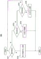
Fig. 20 is a diagram for explaining a solid-state imaging device according to a fifth embodiment of the present invention, and shows an example of a process of selecting a time stamp ADC mode operation and a linear ADC mode operation.
The solid-state imaging device 10D according to the fifth embodiment differs from the solid-state imaging device 10 according to the first embodiment in the following point.
In the solid-state imaging device 10 according to the first embodiment, a Time Stamp (TS) ADC mode operation and a linear (Lin) ADC mode operation are performed continuously.
In contrast, in the solid-state imaging device 10D according to the second embodiment, the Time Stamp (TS) ADC mode operation and the linear (Lin) ADC mode operation can be selectively performed according to the illuminance.
In the example of fig. 20, in the case of normal illuminance (ST1), the time stamp ADC mode operation and the linear ADC mode operation are performed continuously (ST 2).
When the illuminance is very (extremely) high, which is not the normal illuminance (ST1, ST3), since the probability of the charge overflowing from the photodiode PD1 to the floating diffusion FD1 is high, only the time stamp ADC mode operation is performed (ST 4).
When the illuminance is not very high (extremely) but very low (extremely) instead of the normal illuminance (ST1, ST3, ST5), the probability of charge overflowing from the photodiode PD1 to the floating diffusion layer FD1 is extremely low, and therefore, only the linear ADC mode operation is performed (ST 6).
According to the fifth embodiment, it is possible to obtain effects similar to those of the first embodiment, and to realize high speed and low power consumption of the reading process.
The solid- state imaging devices 10, 10A, 10B, 10C, and 10D described above can be applied as imaging devices to electronic apparatuses such as digital cameras, video cameras, portable terminals, monitoring cameras, and cameras for medical endoscopes.
Fig. 21 is a diagram showing an example of a configuration of an electronic apparatus mounted with a camera system to which the solid-state imaging device according to the embodiment of the present invention is applied.
As shown in fig. 21, the present electronic apparatus 100 includes a CMOS image sensor 110 to which the solid-state image pickup device 10 of the present embodiment is applicable.
Further, the electronic apparatus 100 includes an optical system (lens or the like) 120 that guides incident light to a pixel region of the CMOS image sensor 110 (images a subject image).
The electronic device 100 includes a signal processing circuit (PRC)130 that processes an output signal of the CMOS image sensor 310.
The signal processing circuit 130 performs a specific signal process on the output signal of the CMOS image sensor 110.
The image signal processed by the signal processing circuit 130 may be displayed as a moving image on a monitor including a liquid crystal display or the like, or may be output to a printer, or may be recorded in various forms, for example, directly on a storage medium such as a memory card.
As described above, by mounting the solid-state image pickup devices 10, 10A, 10B, 10C, and 10D as the CMOS image sensor 310, a high-performance, small-sized, and low-cost camera system can be provided.
Further, it is possible to realize an electronic device such as a monitoring camera and a medical endoscope camera which is used for applications in which there are restrictions on installation conditions of the camera, such as installation size, the number of connectable cables, cable length, and installation height.
Description of the main elements
10. 10A, 10B, 10 C.10D: solid-state image pickup device
20: pixel section
30: vertical scanning circuit
40: output circuit
50: sequential control circuit
60: reading unit
100: electronic device
110: CMOS image sensor
111: first side
120: optical system
130: signal processing circuit (PRC)
200: digital pixel
210. PD: photoelectric conversion reading unit
211: output buffer
220: AD converter
221: a comparator, comprising: counter with a memory
230. MEM: memory unit
231:SRAM
310: first support circuit
320: second support circuit
330: third support circuit
700: comparator with a comparator circuit
710: a first amplifier
720: a second amplifier
730: first inverter
740: second inverter
1101: a first substrate surface
1102: second substrate surface
2101: n layer (first conductive type semiconductor layer)
2102: n-layer
2103: n layers
2104. 2106: p + layer
2105. 2110, 2113: p layer
2107: first p layer
2108: second p layer
2109: p-layer
2111. 2115: grid electrode
2112. 2114: n + layer
ADC _ CODE _ B: inverted signal
AZ, VINP: signal
BL: bit line
BMP: micro-bump
CC. C711: AZ capacitor
CL2, C752: second noise band limiting capacitor
CL3, C753: third noise band limiting capacitor
CND 1: first control node
CND 2: second control node
CND 3: third control node
C221: coupling capacitor
C222: output-side load capacitor
C751: first noise band limiting capacitor
DC1, DC2, DC 3: fixed reference voltage
DTP (dynamic time protocol): differential transistor pair
EXP1, EXP2, EXP 3: example (b)
FD. FD 1: floating diffusion layer
GND: ground potential
IC 1-Tr: current transistor
INV1, INV 2: inverter with a voltage regulator
I311, I312: current source
I331: a third current source
L: light (es)
Lin: processing period of linear ADC
LSGN 1: signal line
MCL: micro-lens
ND1, ND712, ND721, ND732, ND 742: output node
ND 2: reading node
ND711, ND 713: node point
ND731, ND 741: input node
NT311, NT 321: NMOS transistor for current mirror
NT711 to NT 713: n-channel MOS (NMOS) transistor
NT721, NT731, NT 741: NMOS transistor
NT 732: NMOS transistor for current control
And (3) OVP: overflow path
PCMPR1, PCMPR 2: period of time
PD 1: photodiode
PI: during the accumulation period
PR 2: during reset
PT: during transmission
PT 711-PT 713: p-channel MOS (PMOS) transistor
PT 721: PMOS transistor
PT731, PT741, PT742, PT 751: PMOS transistor
PXLC: digital pixel unit
RAMP: ramp signal
RST and TG: control signal
RST_COMP:
RST 1-Tr: reset transistor
SCMP, VCOMPOUT: output of
SF 1-Tr: source follower transistor
SPL: separating layer
ST 1-ST 6: step (ii) of
SW-RST: reset switch
SW1, SW2, SW 3: switch with a switch body
TG 1-Tr: transmission transistor
TS: processing period of time-stamped ADC
T1-T6: time of day
Vaz, vinm _ vir, Vrlo: voltage of
VBNOTA, VBNINV, VBPINV: bias control signal (grid bias voltage)
VDD: supply voltage
Vdd: power line
VFDini: highest level
VFDsat: lower level
vout 1: output signal
VRAMP: ramp reference voltage
VREF: reference voltage
VREFramp: ramp voltage
VREFrst, VREFsat: voltage level
VSS: reference potential
VSL: voltage signal
Vth: transition waveform
WL: word line
X, Y, Z: direction of rotation