The present application is a divisional application of chinese patent application No.201580020656.2 (PCT/US 2015/020887) with application date of 2015, 3-17 and the name of "cannula seal assembly".
A portion of the disclosure of this patent document contains material which is subject to copyright protection. The copyright owner has no objection to the facsimile reproduction by anyone of the patent document or the patent disclosure, as it appears in the patent and trademark office patent file or records, but otherwise reserves all copyright rights whatsoever.
This application claims the benefit of U.S. provisional patent application No.61/954,227 (application 3, 17, 2014), which is incorporated herein by reference.
Is not applicable.
Detailed Description
This description of illustrative aspects, embodiments, implementations, or applications of the present invention should not be taken as limiting—defining the claims of the invention that are being protected. Various mechanical, compositional, structural, electrical, and operational changes may be made without departing from the spirit and scope of this description and the claims. In some instances, well-known circuits, structures, or techniques have not been shown or described in detail in order not to obscure the invention. The same numbers in two or more drawings represent the same or similar elements. Headings are for the aid of the reader and do not form part of the description.
Furthermore, the terminology of this description is not intended to be limiting of the invention. For example, spatially relative terms such as "below … …," "below … …," "lower," "above … …," "upper," "proximal," "distal," and the like may be used to describe one element or feature's relationship to another element or feature as illustrated in the figures. In addition to the positions and orientations shown in the figures, these spatially relative terms are intended to encompass different positions (i.e., positions in space) and orientations (i.e., rotational placement in space) of the device in use or operation. For example, if the device in the figures is turned over, elements described as "below" or "beneath" other elements or features would then be oriented "above" or "over" the other elements or features. Thus, the exemplary term "below … …" can encompass both a position and orientation of above and below. The device may be otherwise oriented (rotated 90 degrees or at other orientations) and the spatially relative descriptors used herein interpreted accordingly. Likewise, descriptions of movements along and around different axes include different particular device positions and orientations. Also, unless the context indicates otherwise, geometric terms (e.g., "parallel," "perpendicular," "circular," or "square") are not intended to require absolute mathematical precision. Alternatively, such geometric terms allow for variations due to manufacturing or equivalent functions. For example, if an element is described as "circular" or "substantially circular," then this description still encompasses components that are not precisely annular (e.g., one of a slightly oblong or polygonal shape).
In addition, the singular forms "a", "an" and "the" are intended to include the plural forms as well, unless the context indicates otherwise. Moreover, the terms "comprises," "comprising," "includes," "including," and the like, specify the presence of stated features, steps, operations, elements, and/or components, but do not preclude the presence or addition of one or more other features, steps, operations, elements, components, and/or groups. Components described as coupled may be directly coupled, either electrically or mechanically, or may be indirectly coupled via one or more intermediate components.
Elements described in detail with respect to one embodiment, implementation or application may be included in other embodiments, implementations or applications not specifically shown or described whenever possible. For example, if an element is described in detail with respect to one embodiment and is not described with respect to a second embodiment, that element nonetheless may be required to be included in the second embodiment. Thus, to avoid unnecessary repetition in the following description, unless one or more elements will cause an embodiment or implementation to fail, or unless two or more of the elements provide a conflicting function, one or more elements associated with one embodiment, implementation or application may be shown and described as being incorporated into other embodiments, implementations or aspects.
The term "flexible" in relation to a part (e.g., a mechanical structure, component, or assembly of components) should be construed broadly. Essentially, the term means that the part can be repeatedly bent and restored to its original shape without damaging the part. Many "rigid" objects have slight spring back "pliability" due to material properties, although such objects are not considered "flexible" when that term is used herein. The flexible part may have an infinite degree of freedom (DOF). Examples of such parts include closed, flexible tubes (made of, for example, NITINOL, polymers, soft rubber, and the like), coil springs, and the like, which can generally be bent into various simple or compound curves without significant cross-sectional deformation. Other flexible parts may approximate this infinite DOF part by using a series of small pitch assemblies similar to a serpentine serial "vertebra" arrangement. In this vertebral arrangement, each component is a short link in the kinematic chain, and movable mechanical constraints between each link (e.g., pin hinges, cups and balls, living hinges, and the like) may allow one (e.g., pitch) or two (e.g., pitch and yaw) DOF of relative movement between the links. The short, flexible part may function and be modeled to provide a single mechanical constraint (junction) of one or more DOF between two links in a kinematic chain, even though the flexible part itself may be a kinematic chain consisting of several coupled links. The musician will understand that the flexibility of a part can be expressed in terms of its stiffness.
Mainly based on the use of da commercialized by intuitive surgical company of sonyverer, california
Embodiments of the surgical system describe aspects of the invention. However, those of skill in the art will understand that the inventive aspects disclosed herein may be embodied and carried out in different ways, including remotely operated examples and implementations, and if applicable, non-remotely operated examples and implementations. About da->
The embodiments of the surgical system are merely exemplary and are not to be considered as limiting the scope of the inventive aspects disclosed herein.
Sealing assembly
Fig. 1 is a diagrammatic cross-sectional view of a seal assembly 1 for a minimally invasive surgical instrument. The proximal and distal orientation directions are depicted as indicated by the arrows, and these orientations are generally applied throughout this description and the associated figures. As shown in fig. 1, a seal assembly 1 is disposed in a proximal end of a cannula 2, typically within a cannula bowl (bowl) at the proximal end of the cannula, and a portion of a minimally invasive surgical instrument 3 is shown extending through the seal assembly 1 and the cannula 2 toward a surgical site 4 within a patient's body. The surgical instrument 3 may optionally include various distal assemblies, such a surgical end effector 3a having one or more mechanical DOFs, and a wrist mechanism 3b having one or more mechanical DOFs that allows the surgeon to change the orientation of the end effector 3 a. When the surgeon manipulates the instrument during the surgical procedure, the surgical instrument 3 is typically inserted distally and withdrawn proximally (i.e., reciprocated) through the seal assembly 1 and the cannula 2 multiple times. As described in detail below, a latch (not shown) holds the seal assembly 1 in place with respect to the cannula 2.
As shown, the seal assembly 1 includes a lower housing 5 and an upper housing 6 that when assembled together form a seal assembly housing. The lower housing 5 and the upper housing 6 are shown as two separate pieces joined to form a complete single housing, and optionally the complete seal assembly housing is formed as a single piece. The seal assembly 1 further includes a dust seal 7 and a fluid (e.g., gas, liquid) backflow seal 8. Several embodiments of the dust seal 7 are described in detail below. The backflow prevention seal 8 may optionally be one of several seal forms, in which one or more slits remain closed (by inherent elastomeric properties and by resisting fluid pressure distal of the seal) to prevent backflow of fluid through the seal, but which slit is opened to allow fluid or objects to pass through the seal. Such seals include single slit "duckbill" forms, cross-slit tri-fold forms, cross-slit (also referred to as "cross slit" or "cross") forms, and S-curve forms. Other backflow-preventing type seals (e.g., trapdoors, check valves, and the like) may be used.
In use, the anti-reflux seal 8 is closed as shown by the dashed line substitution 9, which prevents the leakage of surgical insufflation gas or other fluids from the cannula when no surgical instrument is inserted into the cannula. When the surgical instrument is inserted into the cannula, the anti-reflux seal 8 is opened and the dust seal 7 seals the surgical instrument shaft to likewise prevent insufflation gas or other fluid from leaking out of the cannula. Thus, the dust seal 7 and the anti-reflux seal 8 cooperate to prevent insufflation gas or other fluid from leaking out of the cannula during surgery, whether or not a surgical instrument is inserted into the cannula.
As shown in fig. 1, the dust seal 7 and the backflow seal 8 are sandwiched between the lower housing 5 and the upper housing 6, although other arrangements of holding the seals inside the seal assembly housing are possible, such as by using an adhesive or other means of securing the seals inside the housing. One or more optional spacers (not shown) may also be sandwiched between the upper and lower housings, as described below.
Fig. 1 further illustrates that the seal assembly 1 may be configured to allow insufflation gas to enter the patient and to allow evacuation of gas and suspended particulate matter (e.g., smoke) from the patient, with and without instruments inserted therethrough. As shown, the insufflation/evacuation gas 10 enters/exits a port 11 in the seal assembly 1. As shown, the port 11 is in the seal assembly housing-through the lower housing 5. The inlet gas then flows between the inner side wall of the lower housing 5 and the outer side wall of the anti-reflux seal 8 to enter the patient through the cannula or through the gap between the surgical instrument 3 and the inner wall of the cannula. The exhaust gas follows a reverse path. Details of example configurations that allow the insufflation/exsufflation gases to pass through the seal assembly 1 are given below. Two or more ports 11 may optionally be used to ensure that a clear path exists that allows gas to pass through the seal assembly.
In some embodiments, the seal assembly 1 includes an instrument insertion guide 12 positioned on a proximal side of the dust seal 7. The instrument insertion guide 12 helps guide the distal end of the surgical instrument into the dust seal 7, for example, such that the distal tip of the instrument end effector 3a is urged away from the puncture, tear, catch, or otherwise damage the dust seal 7 when the instrument is inserted. As described in detail below, in some embodiments, the instrument guide 12 is fixed with respect to the seal assembly housing (e.g., it is optionally formed from the upper housing 6 as a single piece), and in other embodiments, the instrument guide is formed as a separate piece from the seal assembly housing, and it is fixed as a separate piece or it is movable with respect to the seal assembly housing.
In one inventive aspect, the combination of the
seal assembly 1 and a surgical instrument inserted through the
seal assembly 1 is considered an assembly. In another aspect, the combination of the sealing
assembly 1 and the cannula 2 is considered an assembly. In yet another aspect,
seal assembly 1, cannula 2, and a hand inserted through both
seal assembly 1 and cannula 2The combination of surgical instruments is considered an assembly. In two additional aspects, the combination of
seal assembly 1 and cannula 2, and the combination of
seal assembly 1, cannula 2, and the surgical instrument inserted through both
seal assembly 1 and cannula 2, are extended to include teleoperated medical devices that control the movement of the surgical instrument. Teleoperated medical devices are known, such as da Vinci commercialized by intuitive surgical company of senyverer, california
Surgical systems, and such medical devices are also referred to by terms such as "surgical system" or "surgical robot". As described above and below, the seal assembly is a component that allows teleoperated medical devices to perform surgery by maintaining a proper airtight seal to the surgical instrument.
FIG. 1A is a diagrammatic cross-sectional view of a portion of a seal assembly 1, similar to FIG. 1 but with several components omitted for clarity. The longitudinal and transverse directions are indicated by marked arrows, wherein longitudinal means a direction generally parallel to the instrument insertion and withdrawal axis and transverse means a direction generally perpendicular to the instrument insertion and withdrawal axis. Fig. 1A shows the shaft of a surgical instrument 3 inserted through a dust seal 7. The dust seal 7 includes an inner seal portion 13 and an outer flexible portion 14 surrounding the seal portion 13. The flexible portion 14 allows the sealing portion 13 to move distally and proximally along the longitudinal axis a as the surgical instrument 3 is inserted and withdrawn through the dust seal 7. The flexible portion 14 also allows the sealing portion 13 to move laterally (edge-to-edge) within the surgical instrument housing. The sealing portion 13 includes an upper annulus 15 and a lower annulus 16 opposite the upper annulus 15. The upper face 15 and the lower face 16 meet at an annular dust seal lip (lip) 17 to form a circular opening, and the lip 17 seals against an outer shaft surface 18 of the surgical instrument 3. The sealing portion 13 is relatively thicker than the flexible portion 14 and thus the sealing portion is harder than the flexible portion 14. However, the sealing portion 13 is laterally flexible enough so that it can accommodate a variety of instrument shaft diameters. In one embodiment, for example, the dust seal 7 effectively seals surgical instrument shaft diameters in the range of 4.7mm to 9.4mm (referred to as the range of 5mm to 8 mm). In another example embodiment, the dust seal 7 effectively seals surgical instrument shaft diameters in the range of about 9.7mm to 14.2mm (referred to as the range of 10mm to 12 mm). The dust seal may be sized to accommodate a variety of other diameter ranges, or it may be made of a material best suited to work with a single particular instrument shaft diameter.
As shown, the upper face 15 is angled at an angle a with respect to the axis of the instrument 3 and the lower face 16 is angled at an angle β with respect to the axis of the instrument 3. Another way to describe this is that the angles α and β are angled with respect to a longitudinal axis a defined between the top and bottom of the seal assembly such that the surgical instrument is inserted and withdrawn along the longitudinal axis a. Angle alpha is smaller (sharper) than angle beta. Accordingly, the radial width of the upper face 15 is greater than the radial width of the lower face 16. When the surgical instrument 3 is inserted distally through the dust seal 7, the contact between the sealing lip 17 and the upper face 15 tends to move the sealing portion 13 distally against the shaft outer surface 18. Likewise, as the surgical instrument 3 is withdrawn through the dust seal 7, contact between the sealing lip 17 and the underside 16 against the shaft outer surface 18 tends to move the sealing portion 13 proximally.
The relatively thick sealing portion 13, as well as the angular and/or radial width of the upper and lower faces 15, 16, provides several advantages. Typical membrane barrier seals have a uniform or nearly uniform thickness and are therefore subject to perforation and tearing by the instrument tip upon instrument insertion. The greater thickness of the sealing portion 13 with respect to the flexible portion 14 helps to guard against perforation or tearing when the instrument is first inserted, and furthermore the flexible portion 14 provides overall seal longitudinal and transverse flexibility similar to that of a thin diaphragm seal. As described below, in some configurations, the flexible portion 14 provides superior flexibility characteristics for the dust seal 7 as compared to typical membrane diaphragm seals because the flexible portion 14 can be made thinner as it is not contacted by the instrument. This overall flexibility accommodates longitudinal and lateral movement of the instrument shaft within the seal assembly during initial insertion, removal, and use. The relatively steep angle a of the upper face 15 helps to guide the instrument tip into the hole formed by the sealing lip 17, further reducing the risk of perforation or tearing. The thickness of the sealing portion 13 resulting from the lip 17 being compressed against the instrument shaft to form a thicker contact with the instrument shaft, as well as the increased outward thickness of the sealing portion 13, also helps reduce or eliminate the problem of a portion of the sealing lip 17 being stretched into an oblong shape and separating from the instrument shaft surface 18 as the shaft moves laterally within the seal assembly, which breaks the seal by forming an opening between the lip 17 and the surface 18. This situation is sometimes referred to as a "cat eye" condition due to the resulting seal opening shape, and is even more a problem for instrument shaft diameters at the low end of the diameter range that the membrane separator seal can accommodate. Due to the generally triangular cross-sectional shape of the sealing portion 13, with an apex at the lip 17, the circular opening readily extends to accommodate various instrument shaft diameters while retaining a dust seal function and significantly reducing longitudinal bending of the sealing portion 13. The generally smaller amount of material near the circular opening allows the sealing portion 13 to compress laterally outward with relatively less resistance, and the generally larger amount of material away from the circular opening tends to cause the sealing portion 13 to increasingly resist laterally outward compression as the circular opening is further extended.
It can be seen that due to the relatively large radial width of the upper face 15 compared to the radial width of the lower face 16, relatively more of the upper face 15 will contact the instrument shaft surface 18 when the instrument is inserted and withdrawn compared to the lower face 16. In other words, the contact area between the upper face 15 and the instrument shaft is larger than the contact area between the lower face 16 and the instrument shaft. This contact results in a relatively high friction force between the dust seal 7 and the instrument shaft surface 18 when an instrument is inserted and a relatively low friction force when the instrument is withdrawn. The lower friction during withdrawal of the instrument helps to prevent the dust seal 7 from being pulled proximally when the instrument is fully withdrawn, and thus helps to prevent the dust seal from reversing proximally through the upper opening of the seal housing. In view of the illustrative dust seal embodiments shown in the drawings and described below, those skilled in the art will appreciate that even if angles α and β are equal, or even if angle α is greater than angle β, seal portion 13 may optionally be configured such that the radial width (i.e., contact area) of upper face 15 is greater than the radial width of lower face 16 in order to provide relatively high instrument insertion friction. Those skilled in the art will appreciate that it may be desirable to provide good sealing functionality with low friction (e.g., low enough to avoid a stick-slip condition), especially in remote operated applications where smooth control is required as the instrument shaft is continuously moved back and forth through the seal. However, such personnel will also understand that there is a need to provide reasonable resistance to instrument insertion such that the instrument cannot inadvertently slide through the seal and injure the patient (e.g., due to the weight of the instrument itself during manual laparoscopic surgery). The described sealing portion of the dust seal provides such increased insertion friction resistance, as well as acceptable insertion/withdrawal friction. Additional asymmetric insertion/withdrawal resistance features and other dust seal 7 features are described in detail below.
As shown in fig. 1A, the flexible portion 14 is longitudinally attached to the outer periphery of the sealing portion 13 at an intermediate position between the upper face 15 and the lower face 16. And, the flexible portion 14 is shown longitudinally aligned with the lip 17. Optionally, however, the flexible portion 14 is attached to the perimeter of the sealing portion 13 at various longitudinal locations, including very proximal and distal locations. Likewise, the flexible portion 14 is optionally disposed in various longitudinal relationships with the lip 17. Examples of such longitudinal attachment and lip alignment are shown in detail below.
First example
Fig. 2 is a front cross-sectional view of an illustrative surgical instrument seal assembly 20. The seal assembly 20 includes a lower housing 21a and an upper housing 21b that when assembled together form a generally cylindrical seal assembly housing 21. As shown, during manufacture, the lower and upper housings 21a, 21b are first aligned with the hex holes and interference pins, and then the lower and upper housings 21a, 21b are secured together using ultrasonic welding. Other well known permanent bonding techniques may be used, such as permanent press fit or the use of adhesives. In one embodiment, the upper and lower housing members 21a, 21b are made of a rigid plastic alloy, and other rigid materials such as plastic or metal may optionally be used.
The lower housing 21a includes a distal end 22 that is inserted into a cannula bowl at the proximal end of a surgical cannula (not shown) that is held outside the cannula, and a proximal end 23. Proximal end 23 is generally optionally larger than distal end 22, and relief surface 24 is disposed below proximal end 23 and held against the proximal end of the cannula. The lower housing 21a further comprises an annular recess 25 in its outer wall surface 26. An O-ring 27 is inserted into the groove 25 and when the seal assembly 20 is inserted into the cannula bowl, the O-ring 27 seals the inner wall surface of the cannula bowl to prevent leakage of the insufflation gas from between the inner side wall of the cannula bowl and the outer side wall of the lower housing 21 a. As discussed in more detail below, the O-ring 27 also allows the seal assembly to rotate within the cannula bowl while maintaining a seal between the seal assembly and the cannula bowl. The skilled artisan will appreciate that the O-ring 27 represents a variety of filling-type or gasket-type seals that may be generally referred to as cannula seals and that are used to seal between the outer sidewall of the seal assembly and the inner sidewall of the cannula bowl, in some embodiments allowing the seal assembly to rotate within the cannula bowl while maintaining a seal.
The lower housing 21a further includes an inner wall surface 28 that tapers slightly laterally outwardly toward the distal end 22 to allow for increased lateral movement of the backflow seal (see also, e.g., fig. 7 showing an extended backflow seal). As shown in fig. 2, the inner wall surface 28 is optionally slightly necked down near the upper housing portion 21 b. The necking increases the structural strength in the lower housing portion. As also shown in fig. 2, a number of optional radially inwardly projecting ribs 29 are in this necked down region. The ribs 29 help prevent the outer sidewall surface of the reflux seal from blocking gas flow as gas passes between the inner sidewall of the housing and the outer sidewall surface of the reflux seal to enter or exit the surgical site via ports in the seal assembly.
As shown in fig. 2, the lower housing 21a also includes an optional gas valve 30 that includes a valve body 31, a rotary valve member 32, an external fitting 33 (e.g., a threaded Luer (Luer) lock as shown), an internal fitting 34 (e.g., a Luer taper fitting as shown), and a gas channel 30a. As shown, the valve member 32 is snap-fit and rotationally fixed in the valve body 31 using an annular fixing flange 35. In some embodiments, one or more optional support ribs 30b are placed between the valve body 31 and the seal assembly housing 21 to provide additional structural strength to help prevent the valve 30 from getting out of the housing 21. As shown, the lower housing 21a, the valve body 31, the external fitting 33, and the support rib 30b are formed as a unitary, single piece, and optionally they may be formed as two or more pieces that are joined together. During surgery, an insufflation gas supply (not shown) may be coupled to the fittings 33, 34 and the valve member 32 rotated to allow gas to flow inwardly through the passage 30a into the seal assembly. Alternatively, an exhaust gas receiver (evacuation gas sink) (not shown; e.g., a vacuum source) may be coupled to the fittings 33, 34, and the valve member 32 rotated to allow gas to flow outwardly from the seal assembly through the passage 30a.
The upper housing 21b contains an optional distally tapered annular funnel portion 36, which results in an optional annular instrument insertion guide 37 extending distally toward the underlying dust seal. Together, the funnel portion 36 and instrument insertion guide 37 define an annular aperture 38 in the upper housing 21b centered about the longitudinal centerline of the seal assembly through which instruments are inserted. The diameter of the aperture 38 is larger than the aperture in the underlying dust seal, and the relationship between the diameter of the aperture 38 and the size of the upper surface of the dust seal is discussed in detail below. The funnel portion 36 helps guide the surgical instrument tip toward the aperture 38, and the instrument guide 37 helps align and guide the insertion of the instrument tip through the underlying dust seal.
The upper housing 21b optionally includes one or more latch receiving features 39 that allow for the detachable coupling of an object to the housing 21. As shown, the latch receiving feature 39 is a window that allows a obturator latch (not shown) to extend through and engage an inner surface of the upper housing 21B to keep the obturator (not shown) fully inserted into the seal (see fig. 15A-15B and associated text below). The obturator latch engages below the perimeter defining the window. The cannula, seal, and obturator together form an assembly that allows the surgeon to insert the cannula through the body wall of the patient. It should be appreciated that the latch receiving feature 39 as shown represents a number of well known latch mechanisms that would allow for the detachable coupling of a obturator or other object to the top of the housing 21. In another example, a latch on the second seal assembly (not shown) holds the second seal assembly against the top of the housing 21. See, for example, U.S. patent No.6,123,689 (showing a "damper" seal that can be removably coupled to the top of a main seal assembly). The second seal assembly includes a dust seal bore having a smaller diameter than the diameter of the bore of the dust seal in the housing 21. The second seal assembly, when coupled to the housing 21, forms various additional combinations similar to those described elsewhere herein.
As shown in fig. 2, the backflow prevention seal 40 is sandwiched between the lower housing 21a and the upper housing 21 b. As depicted in this embodiment, the backflow prevention seal 40 is a cross slit seal. The thickness of each of the folded side walls 41 of the back-flow prevention seal 40 tapers slightly toward the distal end 42 of the seal 40. The thicker folded sidewall 41 at the proximal end of seal 40 helps the anti-reflux seal snap back to the (snap back to) closed position when the instrument is removed. The thinner folded sidewall 41 at the distal end of the seal 40 provides increased sidewall flexibility and creates a lower friction force between the seal 40 and the instrument as the instrument is inserted through the seal 40. The relatively thin distal wall 41 also helps keep the seal closed when the instrument is removed by fluid back pressure on the outer surface of the sidewall. The backflow prevention seal 40 is oriented within the lower housing 21a such that one of the inward folds of the side walls 41 is aligned with the gas channel 34 (i.e., as shown, the outward fold of an adjacent side wall 41 is offset 45 degrees from the gas channel 34) so as to ensure adequate gas flow through the folded side walls 41 that is urged against the ribs 29 as the instrument is inserted through the backflow prevention seal 40. The interior of the anti-reflux seal 40 is made sufficiently deep longitudinally and wide laterally so that the anti-reflux seal 40 does not interfere with the movement of the overlying (overlaying) dust seal as the dust seal moves longitudinally and laterally. In an exemplary embodiment, the backflow prevention seal 40 is made of a medical grade elastomeric material, such as chlorinated polyisoprene or other rubber material (e.g., silicone, urethane, etc.). Other suitable materials may be used.
FIG. 2 shows an optional annular spacer 43 disposed on the backflow prevention seal 40 and sandwiched between the lower and upper housing portions 21a, 21 b. As described in more detail below, in some embodiments, the annular spacer 43 is combined with a latch that detachably secures the housing 21 to the cannula as a single piece. In some embodiments, the spacer 43 is disposed on both the dust seal and the backflow seal such that the outer peripheries of the dust seal and the backflow seal are in contact. However, as depicted, the spacer 43 is disposed between the dust seal and the back-flow prevention seal, which provides more longitudinal space between the dust seal and the proximal side of the back-flow seal, and thus allows the dust seal to operate properly without contact interference from the back-flow prevention seal. The spacer 43 may optionally include one or more annular bosses that compress either or both of the backflow-preventing seal and the dust-preventing seal when the upper and lower housing members are secured together so as to ensure a gas-tight seal between each seal and the housing, and so as to prevent each seal from rotating within the housing.
As depicted, the dust seal 44 is disposed on the annular spacer 43 such that the dust seal overlies the backflow prevention seal 40 (or proximal to the backflow prevention seal). The instrument aperture in the dust seal 44 is aligned at the intersection of the cross slit in the back-flow prevention seal 40 such that the instrument passes through the center of both the dust seal and the back-flow prevention seal. Details of the dust seal are discussed in more detail below.
As depicted, an optional annular spacer 45 is disposed on the outer perimeter (proximal) of the dust seal 44. When in use, the annular spacer 45 helps to distribute the pressure of the upper housing 21b against the dust seal 44. Additionally, the annular spacer 45 may optionally include a dust seal anti-reverse feature described in more detail below.
Thus, fig. 2 shows a dust seal 44 disposed above the backflow prevention seal 40 in the seal housing 21, sandwiched between the lower and upper housings 21a and 21b, along with optional spacers 43 and 45.
Dust-proof sealing member
Fig. 3 is an upper perspective view of an example dust seal embodiment, fig. 3A is an upper perspective cross-sectional view of the dust seal embodiment shown in fig. 3, and fig. 3B is a top plan view of the dust seal embodiment shown in fig. 3. Fig. 4 is a lower perspective view of the dust seal embodiment shown in fig. 3, fig. 4A is a lower perspective cross-sectional view of the seal embodiment shown in fig. 3, and fig. 4B is a bottom plan view of the embodiment shown in fig. 3. To avoid lengthy descriptions, the various features described with respect to this dust seal embodiment, as well as the dust seal features described above, are applicable to the other dust seal embodiments described above and below.
Referring to fig. 2, 3A, 3B, 4A, and 4B, the dust seal 44 is generally annular and includes an annular outer peripheral portion 45, an annular inner sealing portion 46, and an annular flexible portion 47 between the peripheral portion 45 and the sealing portion 46. The peripheral portion 45 supports the dust seal 44 within the housing 21 such that the seal portion 46 is able to move longitudinally and laterally as the instrument shaft moves within the housing 21 through the dust seal 44. As depicted, the peripheral portion 46 has an optional smaller annular boss on its distal side, and various other optional configurations (e.g., annular boss on the proximal side, interrupted annular boss or protrusion, etc.) may be used to mount the dust seal 44 within the seal assembly housing. The sealing portion 46 functions as generally described with reference to fig. 1 and 1A. The seal portion includes an annular upper face 48 and an annular lower face 49 that meet (meet) at an annular seal lip 50 that define a bore through which the surgical instrument shaft is inserted and withdrawn. The sealing lip 50 seals against the outer surface of the surgical instrument shaft. The sealing lip 50 may be formed as a single circular surface, or optionally it may be formed as other surface shapes, such as flat, corrugated, etc. Optionally, one or more small, discontinuous annular rings are placed over lip 50 for sealing the instrument shaft. The sealing portion 46 is flexible and thus it accommodates a variety of instrument shaft diameters (e.g., about 5mm to 8.5mm or about 10mm to 12 mm) -the dimensions of the sealing portion 46 can be varied to accommodate other diameter ranges as appropriate). It can be seen that the radial width of the upper face 48 is greater than the radial width of the lower face 49 and that the angle between the upper face 48 and the insertion instrument shaft is sharper than the angle between the lower face 49 and the insertion instrument shaft.
The flexible portion 47 encloses the sealing portion 46 and (i) allows the sealing portion 46 to move distally and proximally (longitudinally) within the sealing assembly, (ii) allows the sealing portion 46 to move side-to-side (laterally) within the sealing assembly without significant deformation (thus reducing the "cat eye" problem described above), and (iii) accommodates the radially outwardly stretched sealing portion 46 when a larger diameter instrument shaft is inserted. Thus, the benefits of the various aspects of the sealing portion 46 are combined with the benefits of the flexible portion 47. As shown, the flexible portion 47 has a generally annular folded bellows (bellows) configuration, alternatively described as an annular bellows configuration, including one or more upper (proximally oriented) annular folds and/or one or more lower (distally oriented) annular folds, with annular grooves spacing adjacent upper folds from adjacent lower folds (i.e., the grooves are formed by inversions of the folds). The folds act as hinges, although the flexible portion 47 material between the folds may also stretch. In other embodiments, other suitable flexible portion 47 configurations may be used, including, for example, flat (planar) diaphragms, annular diaphragms having constant or varying thicknesses.
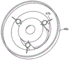
In the depicted embodiment, the flexible portion 47 is joined to the sealing portion 46 at an inner upper annular fold 51 and to the peripheral portion 45 at an outer upper annular fold 52. There is a lower annular fold 53 between the upper annular folds 51 and 52. Thus, a lower annular groove 54 is formed between the sealing portion 46 and the lower annular fold 53, and an upper annular groove 55 is formed between the upper annular folds 51 and 52. The support rib 56 is disposed in the lower annular groove 54 and the support rib 57 is disposed in the upper annular groove 55. As shown, each of the support ribs 56 and 57 is five, and other numbers (e.g., three, four, six, or more) may be used. The individual support ribs 56 and 57 are generally disposed opposite one another on the front and back of the dust seal 44, although they may optionally be placed in other relative orientations to one another. In addition, in some embodiments, the number of support ribs 56 may be different from the number of support ribs 57. Also, the support ribs 56 and 57 may optionally be symmetrically or asymmetrically spaced within the annular groove. The symmetrical spacing of three or more support ribs tends to keep the resistance to movement constant in all lateral directions, and the asymmetrical spacing (or use of only two support ribs oriented opposite each other) tends to promote movement in one or more lateral directions.
As shown in fig. 4, 4A and 4B, the support ribs 56 are equally spaced apart in the lower annular groove 54. Each support rib 56 has two portions: truncated semi-annular cylindrical portions 58 joined on both sides of the sealing portion 46; and a mesh portion 59 extending between the semi-cylindrical portion 58 and the outer side wall of the lower annular groove 54. The semi-cylindrical portions 58 of the support ribs 56 are generally arranged to form a fan-shaped pattern around the sealing portion 46. As depicted, the semi-cylindrical portions 58 are slightly spaced apart from one another at the sealing portion 46, and they may optionally contact one another at the sealing portion 46.
Referring to fig. 3, 3A and 3B, the support ribs 57 are equally spaced apart in the upper annular groove 55. Each support rib 57 has two portions: a truncated quarter-round cylindrical portion 60 engaged on one side of the outer side wall of the upper annular groove 55; and a mesh portion 61 extending between the other side of the portion 60 and the inner side wall of the upper annular groove. It can be seen that the shape of the support rib 57 is similar to the shape of the support rib 56, except that the support rib 57 has only about one half of the semi-cylindrical portion of the support rib 56.
Both the support ribs 56 and 57 may have other shapes. For example, the support rib 57 may have a semi-cylindrical portion, or the support rib 56 may have a quarter-cylindrical portion. Other support rib shapes include single, smooth (e.g., S-shaped) or acutely angled (e.g., Z-shaped) folds between the groove sidewalls. The top of the support rib 57 and the bottom of the support rib 57 may be truncated as shown as described, or may be oriented generally parallel to the lateral direction of the seal 44.
As can be seen from fig. 2, 4A and 4B, the attachment of the support rib 56 to the outer side wall of the lower annular groove 54 extends below (distally) the level of the sealing portion 46. This configuration acts as an anti-reverse feature to help prevent the sealing portion 46 from being pulled proximally and expanding the upper annular fold 51 (i.e., reverse seal) during withdrawal of the instrument. The support rib 56 configuration provides relatively little resistance to compression and relatively more resistance to extension. Accordingly, the semi-cylindrical portions 58 of the support ribs 56 allow the sealing portion 46 to stretch open to accommodate larger diameter instrument shaft diameters, which symmetrically compresses the lower annular groove 54. The semi-circular portion 58 also allows the lower annular groove 54 to be asymmetrically compressed as the sealing portion 46 moves laterally within the flexible portion 47.
Thus, providing both anti-reverse benefits and low resistance to compression of the annular groove. The semi-cylindrical shape enables the support rib 56 to extend a relatively short distance with relatively low resistance when the walls of the semi-cylinder are straightened into a V-shape, and thereafter provide relatively high resistance to further extension, which requires the support rib material to stretch itself. The semi-cylindrical shape also allows the support rib 56 to collapse on itself almost completely with little resistance. The skilled person will also appreciate that the semi-cylindrical vertical walls allow for simple shaping so that the complete dust seal may be formed as a single, uniform piece. It can be seen that similar features and advantages exist in the other support rib 56 configurations described above and below as well as in the support rib 57 configurations described below.
Moreover, although specific embodiments have been described, many variations are possible, such as reversing the mesh and semi-cylindrical orientations so that the mesh is closer to the sealing portion (depending on the groove configuration), altering the semi-cylindrical shape to include other curved sides or straight sides, etc. Thus, in general terms, the depicted support rib 56 may be described as having two walls, a first side of each wall being anchored to one of the side walls of the groove 54, and a second side of each wall being joined together and anchored to the other of the side walls of the groove 54. And in addition, the horizontal plane of the outer side wall of the wall engagement groove 54 of the support rib 56 extends below (distally) the horizontal plane of the inner side wall of the wall engagement groove 54 of the support rib 56. Still further, although the inner side walls of the groove 54 are depicted as being defined by the sealing portion 46, the support rib 56 may optionally be placed in any of the grooves in the flexible portion 47.
In some dust seal 46 embodiments, a lubricant 62 (e.g., a medical grade silicone lubricant) is placed in one or more of the pockets formed between the semi-cylindrical portion 58 of the support rib 56 and the seal portion 46. As the surgical instrument is inserted and withdrawn through the sealing portion 46, the flexing of the sealing portion 46 and the flexible portion 47 causes some of the lubricant 62 to be pushed out of the pocket and it then migrates through the underside 49 to lubricate the contact between the surgical instrument shaft and the sealing portion 46. One suitable lubricant is MED-420 of NuSil Technology LLC (at 5,000 cP). Another suitable lubricant is NuSil's MED-361 (at 12,5000 cP), and other suitable lubricants of various viscosities may be used.
Referring now to fig. 2, 3A and 3B, it can be seen that due to the sidewall angle of the upper annular groove 55 with respect to the longitudinal axis, the support rib 57 orientation in the upper annular groove 55 is generally opposite to the support rib 56 orientation in the lower annular groove 54. The horizontal plane at which each support rib 57 is attached to the outer side wall of the upper annular groove 55 extends above (proximally) the horizontal plane at which each support rib 57 is attached to the inner side wall of the upper annular groove 55 (the top of which is the location where the flexible portion 47 engages the sealing portion 46). This configuration helps to prevent the sealing portion 46 from being pushed distally and possibly unfolding the lower annular fold 53 during instrument insertion. The combination of the quarter-cylindrical portion 60 of the support rib 57 and the mesh 61 functions similarly to the combination of the half-cylindrical portion 58 of the support rib 56 and the mesh 59, and similar configuration variations as described above are possible. It can be seen that each support rib 57 is slightly larger than each support rib 56. The quarter-cylindrical portion 60 serves to further reduce the resistance to shrinkage compared to the half-cylindrical portion 58 such that the upper annular groove 55 tends to shrink symmetrically as the seal portion 46 extends to accommodate a relatively large instrument shaft diameter, and the groove 55 tends to shrink asymmetrically as the seal portion 46 moves laterally. However, in some embodiments, the support rib 57 includes a semi-cylindrical portion (or variation) similar to the support rib 56. Also, for the support ribs 56 in the plurality of lower annular grooves, if the flexible portion 47 includes a plurality of upper annular grooves, the support ribs 57 may be placed in any number of upper annular grooves.
As mentioned above, various other support rib configurations may be used in the upper or lower groove formed by the annular fold in the flexible portion of the dust seal. Fig. 3C and 3D are top and perspective views of the dust seal 46a with equally spaced support ribs 57a disposed in the flexible portion grooves. The support ribs 57a each include a truncated conical portion oriented in the longitudinal direction, having an apex toward the bottom of the groove, and having conical portion walls coupled to the inner and outer side walls of the groove by smaller mesh portions. The truncated cone shape is optionally straight or inclined as illustrated, optionally annular or other shape as illustrated.
Fig. 3E and 3F are top and perspective views of the dust seal 46b with equally spaced support ribs 57b disposed in the flexible portion grooves. The support ribs 57b each comprise a cylinder oriented in the longitudinal direction in the groove, and the cylinder walls are coupled to the inner and outer side walls of the groove by smaller web portions. The diameter of the cylinder in the support rib 57b is slightly smaller than the groove width at the top of the groove.
Fig. 3G and 3H are top and perspective views of the dust seal 46c with equally spaced support ribs 57c disposed in such grooves. Like the support ribs 57b, the support ribs 57c each include a cylinder oriented in the longitudinal direction in the groove, and the cylinder wall is coupled to the inner side wall and the outer side wall of the groove by small mesh portions. The diameter of the cylinder in the support rib 57c is larger than the diameter of the cylinder in the support rib 57b, which is about the groove width at the groove top.
Fig. 3I and 3J are top and perspective views of the dust seal 46d with equally spaced support ribs 57d disposed in the flexible portion grooves. In contrast to the support rib 57a (fig. 3C and 3D), the support rib 57D is a truncated semi-conical portion, wherein one side of the conical portion is coupled to the inner sidewall of the groove and the other side of the conical portion is coupled to the outer sidewall of the groove.
Fig. 3K and 3L are top and perspective views of the dust seal 46e with equally spaced support ribs 57e disposed in the flexible portion grooves. The configuration of each support rib 57e is similar to that of support rib 56 (fig. 4, 4A and 4B), except that fig. 3K and 3L illustrate that a truncated semi-cylindrical configuration may be disposed in the top groove, and that the truncated semi-cylinder may be oriented with its radially outward opening.
Fig. 3M and 3N are top and perspective views of the dust seal 46f with equally spaced support ribs 57f disposed in the flexible portion upper groove. The configuration of each support rib 57f is similar to that of the support rib 57 (fig. 3, 3A, and 3B).
Fig. 3O and 3P are top and perspective views of the dust seal 46g with equally spaced support ribs 57g each disposed in a flexible portion groove. Each support rib 57g is configured as a serpentine S-curve with one side edge of the support rib coupled to the inner side wall of the groove and the other side edge of the support wall coupled to the outer side wall of the groove. As depicted, the support rib-attached groove inner and outer sidewall locations are at the same clock location (shown at 12 o ' clock, 4 o ' clock, and 8 o ' clock locations) centered on the dust seal, with the serpentine folds in the rib extending on both sides of this clock location.
Fig. 3Q and 3R are top and perspective views of the dust seal 46h with equally spaced support ribs 57h each disposed in a flexible portion groove. Each support rib 57h is configured similar to the serpentine S-curve of support rib 56g (fig. 3O and 3P), except that the serpentine folds in support rib 57h extend farther along the dial than the serpentine folds in support rib 57g (i.e., have a greater magnitude).
Fig. 3S and 3T are top and perspective views of the dust seal 46i with equally spaced support ribs 57i each disposed in a flexible portion groove. Each support rib 57i is configured as a serpentine S-curve with one side edge of the support rib coupled to the inner sidewall of the groove at one clock position centered on the dust seal and the other side edge of the support rib coupled to the outer sidewall of the groove at another clock position (e.g., displaced clockwise as shown). As shown in fig. 3S and 3T, the serpentine fold does not extend beyond the clock position where the support rib is attached to the sidewall. And the clock position at which each support rib is attached to the inner side wall of the groove is different from the clock position at which each support rib is attached to the outer side wall of the groove. As shown, for example, one rib is attached to the inner sidewall at the 12 o 'clock position and to the outer sidewall at the 1 o' clock position.
Fig. 3U and 3V are top and perspective views of the dust seal 46j with equally spaced support ribs 57j each disposed in a flexible portion groove. The configuration of each support rib 57j is similar to that of support rib 57i (fig. 3S and 3T), except that one of the serpentine folds of the support rib (e.g., the fold closer to the sealing portion as shown) extends beyond the clock position where the support rib is attached to the side wall.
Fig. 3W and 3X are top and perspective views of the dust seal 46k with equally spaced support ribs 57k each disposed in a flexible portion groove. The configuration of each support rib 57k is similar to that of support rib 57i (fig. 3S and 3T), except that the serpentine fold of the support rib extends beyond the clock position where the support rib is attached to the side wall. This embodiment, as well as the embodiments shown in fig. 3U and 3V, illustrates that the serpentine folds in the support ribs need not be symmetrical.
Fig. 3Y and 3Z are top and perspective views of the dust seal 46m with equally spaced support ribs 57m each disposed in a flexible portion groove. The support rib 57m is a composite variant of the support rib generally described in fig. 3S to 3X. As shown, longitudinally oriented annular walls (i.e., cylinders) 57m-i are disposed between the groove sidewalls, and then serpentine support ribs are coupled between the groove inner sidewall and the annular walls and between the annular walls and the groove outer sidewall. As shown, for example, support rib portions 57m-ii are coupled between the groove inner side walls and annular walls 57m-i, and support rib portions 57m-iii are coupled between annular walls 57m-i and groove outer side walls. Each support rib portion 57m-ii and 57m-iii is configured similar to support rib 57i (fig. 3S and 3T), although other configurations may be used. The support rib configuration shown in fig. 3Y and 3Z illustrates that a web of interconnected support ribs may be disposed in one or more of the grooves in the flexible portion of the dust seal. Embodiments include any support rib configuration.
Fig. 3AA and 3AB are top and perspective views of the dust seal 46n with equally spaced support ribs 57n each disposed in such a groove. As shown, each of the support ribs 57n is a radial straight rib between the inner and outer side walls of the groove. The rib 57n provides a strong tensile resistance and, thus, as shown, provides a good seal anti-reverse feature when disposed, for example, in the innermost lower groove of the dust seal flexible portion. For relatively small radial movements of the sealing portion of the dust seal (e.g., small increases in diameter or small lateral movements from the instrument shaft), the rib 57n depends on the resilient compressibility of its material. And for relatively large radial movements of the sealing portion of the dust seal, the ribs 57 flex elastically in dependence of their material.
Referring to fig. 2, it can be seen that the dust seal 44 is optionally sized such that the upper annular fold 51 is generally below (distal) the annular distal end of the instrument insertion guide 37. This configuration also helps prevent the dust seal 44 from reversing as the instrument is withdrawn, as the instrument insertion guide 37 helps prevent the relatively thicker and less flexible seal portion 46 from moving proximally as the instrument is withdrawn. Further, the diameter of the instrument insertion hole 38 is sized to inwardly overhang the outer periphery of the sealing portion 46 such that the tip of the instrument being inserted will tend to contact the angled upper face 48 of the sealing portion 46 and thus urge the tip through and not puncture or tear the dust seal 44. As shown, for example, the diameter of the instrument insertion hole 38 is smaller than the outer peripheral diameter of the upper face 48 such that the insertion instrument tip will first contact the upper face 48 of the thicker seal portion 46. In this configuration, the instrument tip is guided from contacting and potentially damaging the relatively thin flexible portion 47.
It can also be seen in fig. 2 that there is sufficient space between the lower annular fold 53 and the inner folded sidewall of the back-flow prevention seal 42 that allows the seal portion 46 to move distally and laterally without contacting the back-flow prevention seal. In some embodiments, such as those in which the spacer 43 is made relatively thin or omitted, the flexible portion 47 may contact the inner sidewall of the backflow seal 42, and the angle of the outer sidewall of the flexible portion 47 at or near the contact location still allows the sealing portion 46 to move distally and laterally.
In an exemplary embodiment, the dust seal 44 is made of a medical grade elastomeric material, such as chlorinated polyisoprene or other rubber material (e.g., silicone, urethane, etc.). Other suitable materials may be used.
Second example
FIG. 5 is a front cross-sectional view of a portion of another seal assembly embodiment 63, whose configuration, components, features, and variations are substantially similar to other example seal assembly embodiments in this specification. As shown in fig. 5, seal assembly 63 includes a dust seal 64 (which includes a seal portion 65) and a backflow prevention seal 66. An optional spacer (e.g., fig. 2, element 45) between the dust seal and the upper housing is omitted from the depicted embodiment such that the top surface of the dust seal 64 is coplanar for molding.
As shown, the sealing portion 65 includes an annular upper face 67 that includes an upper (proximal) concave portion 68 that smoothly transitions to a lower (distal) straight face portion 69. The upper annular surface 67 is manufactured similarly to the upper annular surface 48 (fig. 2). The instrument insertion aperture 70 in the housing 71 is sized such that the instrument insertion guide 72 depends slightly inwardly of the upper concave portion 68, as described above. In addition, the upper annular fold 73 of the flexible portion of the dust seal 64 is in contact with or nearly in contact with the distal end of the instrument insertion guide 72. The top surface of the annular fold 73 is shown as optionally flat, and other top surface shapes may optionally be used to allow smooth movement of the sealing portion 65 laterally beneath the distal side of the insertion guide 72.
With respect to fig. 2, regardless of the advantage of the relationship between the distal end of the insertion guide 37 and the sealing portion 46, if an instrument is initially inserted in an orientation that is very offset from the longitudinal axis (e.g., an operating room person may place a tip into an instrument insertion hole and then tilt the instrument until it is aligned for insertion, see, e.g., fig. 7), the tip may enter a smaller gap between the top of the upper annular fold 51 and the bottom of the instrument guide 37. It can be seen that in the dust seal 64 of fig. 5, in contrast to the dust seal 44 of fig. 2 and its sealing portion 46, the upper concave portion 68 (and upper annular fold 73) extends proximally to be proximate to or in contact with the upper housing 71 and its insertion guide 72. This contact or near contact helps prevent the tip of an off-axis inserted instrument from contacting the flexible portion outside of the seal portion 65, and it helps urge the tip of an off-axis inserted instrument through the dust seal. The relatively sharper angle of concave portion 68 with respect to the longitudinal axis of the seal assembly also helps prevent the instrument tip from snapping into the seal portion and thus urges the tip through the dust seal without damaging the seal.
Third example
FIG. 6 is a front cross-sectional view of a portion of another seal assembly embodiment 74, whose configuration, components, features, and variations are substantially similar to other example seal assembly embodiments in this specification. As shown in fig. 6, the seal assembly 74 includes a dust seal 75 (which includes a seal portion 76) and a backflow prevention seal 77. It can be seen that the dust seal 75 and its sealing portion 76 are relatively deep (i.e., longitudinally extending) as opposed to the dust seal 64 (see fig. 5) and its sealing portion 65. The back-flow prevention seal 77 is the same depth as the back-flow prevention seal 40 (fig. 2), and in some embodiments, it may optionally be made deeper to accommodate the dust seal 75 and its longitudinal movement. An optional spacer (e.g., fig. 2, element 45) between the dust seal and the upper housing is omitted from the depicted embodiment.
Similar to the sealing portion 65 (fig. 5), the sealing portion 76 includes an annular upper face 78 that includes an upper concave face portion 79 that smoothly transitions into an annular lower straight face portion 80. With respect to the inserted surgical instrument, the lower straight face portion 80 is formed with a steeper angle (and thus a greater radial width (surface area)) than the straight face portion 69 (fig. 5) (i.e., the face angle is sharper about the longitudinal axis of the seal assembly). Thus, upper annular surface 78 is relatively radially wider than upper annular surface 67 (FIG. 5). The steep angle of the annular lower straight face portion 80 further helps to encourage the instrument tip to pass through the dust seal without perforating or tearing the relatively soft material used to form the dust seal. As shown in fig. 6, the configuration of the instrument insertion guide and dust seal relative to each other is similar to the embodiment shown in fig. 5 and described with respect to fig. 5.
Referring to fig. 2, 5 and 6, it can be seen that at the center of the dust seal, the upper face of the thicker seal portion can have a number of surface variations, including flat, concave and possibly convex annular surfaces, as well as various combinations of such surfaces intermixed with one another. Although not shown, it is contemplated that the underside of the sealing portion may have similar variations.
Fourth example
Fig. 7 is a front cross-sectional view of a portion of another seal assembly embodiment 81, whose configuration, components, features, and variations are substantially similar to other example seal assembly embodiments in this specification. The seal assembly 81 includes a seal assembly housing 82, a backflow prevention seal 83, a dust seal 84 proximal of the backflow prevention seal 83, and an instrument insertion guide 85 disposed on (proximal of) the dust seal 84. An instrument insertion guide 85 is secured to the seal assembly housing and defines an instrument insertion aperture 86 in the housing 82. The insertion guide may be formed as an integral piece of the upper portion of the seal assembly housing, as shown, or it may optionally be formed as a separate piece that is subsequently mechanically or adhesively joined to the upper housing.
As shown in fig. 7, the instrument insertion guide 85 extends distally into (farther to the side of) the seal assembly housing 82 than, for example, the instrument insertion guide 37 extends into the seal assembly housing 21 (fig. 2). The distal end of the instrument insertion guide extends to a depth distal of the location where the dust seal is coupled to the seal assembly housing. As depicted, the instrument insertion guide 85 extends a depth of about 4/10 (which may be more or less, such as 3/10 or 5/10) of the distance between the proximal end 87 and the distal end 88 of the seal assembly housing 82. In other words, the instrument insertion guide 85 extends distally through the plane of the proximal-most portion of the dust seal. In yet another words, in the groove in the upper portion of the flexible portion of the dust seal, the outer sidewall of the groove is longer than its inner sidewall (e.g., about twice as long or more), such that the sealing portion of the dust seal is nearly the longitudinal center of the seal assembly. The extended length of the instrument insertion guide 85 further ensures that the distal tip of the instrument inserted into the seal assembly 81 will contact the upper annular face 88 of the sealing portion 89 of the dust seal 84 at a relatively sharper angle than the angle at which the tip would contact the upper annular face when the instrument insertion guide has a shorter length, such as illustrated in fig. 5 and 6. This enhanced instrument guide feature is illustrated by considering the insertion orientation of one surgical instrument 90, as shown in fig. 7. The surgical instrument at insertion orientation 90a is with respect to a condition that the surgical instrument would exhibit when the length of the instrument insertion guide is as, for example, shown in fig. 2. Thus, the distal tip 91 of the surgical instrument 90 at orientation 90a may contact the upper annular face of the dust seal at a steep angle, which increases the risk that the tip 91 will puncture or tear the dust seal, and in some cases may even distance the tip 91 from passing through the dust seal due to the contact angle of the tip 91 with the annular face. Conversely, the surgical instrument orientation 90b is constrained by the length of the instrument insertion guide 85 such that the distal tip 91 of the surgical instrument 90 will contact the upper annular face of the dust seal at a relatively sharper angle, thus reducing the risk that the tip 91 will puncture or tear the dust seal, and ensuring that the annular face will even more effectively urge the tip 91 toward passing through the dust seal. As shown, the sealing portion 89 has a configuration similar to the sealing portion 65 (fig. 5), and it should be understood that various sealing portion configurations may be used.
As shown in fig. 7, the lengths of the backflow seal 83 and the dust seal 84 are extended to accommodate the increased length of the instrument insertion guide 85. The overall length of the seal assembly housing 81 is generally limited by the depth of the cannula bowl (not shown; see fig. 2) into which it is inserted. To prevent damage to the anti-reflux seal 83 during normal handling, and to prevent the cannula bowl inner surface from interfering with the function of the anti-reflux seal 83 when the instrument is inserted, the length of the anti-reflux seal 83 is configured such that its distal end 92 does not extend past the distal end 88 of the seal assembly 81 when the anti-reflux seal 83 is in the closed (sealed) position. The sealing portion 89 of the dust seal 84 may optionally extend as far into the backflow seal 83 as possible so that the backflow seal 83 does not interfere with proximal-distal and lateral movement of the sealing portion 89 and its adjacent flexible portion. As shown in fig. 7 and 3B, the outer surface of the upper annular groove 93 of the flexible portion may optionally be configured with thick longitudinal stiffening ribs 94, providing additional support to the flexible portion of the dust seal 84 and avoiding proximal reversal of the dust seal at these outer walls. In one illustrative embodiment, each stiffener 94 is disposed between adjacent upper support ribs 95, the stiffener having a width that is about one-half the distance between the support ribs. More or fewer stiffeners 94 may be used at various locations.
Additionally, optional support ribs 96 may be placed around the outer surface of the instrument insertion guide 85, extending radially outward, providing increased support for the instrument insertion guide 85. The distal ends 97 of the radial support ribs 96 are optionally configured to have the same length as the instrument insertion guide 85 such that the inner annular fold of the flexible portion contacts both the distal ends 98 of the instrument guide 85 and the distal ends 97 of the support ribs 96 as the instrument is withdrawn through the dust seal 84. The distal end 97 acts as both a proximal longitudinal motion stop and a lateral motion guide surface. Thus, the proximal range of motion of the sealing portion 89 is limited regardless of its lateral position within the seal assembly housing. This proximal motion limitation avoids the dust seal from temporarily or permanently hooking the insertion guide when the instrument is removed, particularly when the instrument is removed in a direction offset from the longitudinal axis.
An optional radial support rib 99 may be placed under the proximal end 87 of the seal assembly 81 to provide additional structural support. The support ribs 96 and 99 may optionally be blended together to form a generally L-shaped support bracket that extends below the top surface of the upper housing and then distally along the outside of the instrument guide 85.
Fifth example
FIG. 8 is a front cross-sectional view of a portion of another seal assembly embodiment 100, with configurations, components, features, and variations substantially similar to other example seal assembly embodiments in this specification. Fig. 8 shows that the seal assembly 100 includes: a seal assembly housing 101 (which includes a lower housing 101a and an upper housing 101 b), a backflow prevention seal 102 disposed distally within the lower housing 101a, a spacer (and optional latch mechanism) 103 disposed on (proximal to) the backflow prevention seal 102, a dust seal 104 disposed on (proximal to) the spacer 103, and an upper housing 101b disposed on (proximal to) the dust seal 104. The upper housing 101b includes an integrally formed, short, fixed instrument insertion guide 105 and a support rib 106 extending radially outward from the insertion guide 105 below the top of the proximal housing 101b, similar to the seal assembly 20 configuration illustrated in fig. 2.
The dust seal 104 is configured substantially similar to the configuration of the dust seal 84, as illustrated in fig. 7. However, in contrast to the seal assembly illustrated in fig. 7, the seal assembly 100 includes a second, floating instrument insertion guide 107 attached to the seal portion 108 of the dust seal 104 such that the instrument insertion guide 107 moves proximally-distally (longitudinally) and also moves laterally as the seal portion 108 moves.
As depicted in fig. 8, the floating instrument insertion guide 107 is generally cylindrical, having a proximal end 109, a distal end 110, an inner sidewall surface 111, and an outer sidewall surface 112. In one embodiment, the proximal end 109 of the instrument insertion guide 107 optionally contacts or nearly contacts the bottom of the radial support rib 106, which prevents further proximal movement of the instrument insertion guide 107 (and the dust seal 104 is inverted, as described above) and provides a lateral movement guiding surface for the insertion guide 107. Thus, proximal end 109 may slide smoothly laterally while remaining within its proximal range of motion limited by the bottom of radial support rib 106. The distal end of the fixation instrument insertion guide 105 may optionally be manufactured flush with the bottom of the support rib 106, or it may extend beyond the bottom of the support rib 106. Alternatively, an optional spacer may be disposed between the upper housing 101b and the distal end 109 such that the spacer limits proximal travel of the floating instrument insertion guide 107. Referring to fig. 13A, for example, the anti-reverse 152, or similar ring without flexible fingers 154, is an illustrative spacer.) the instrument insertion guide 105 inwardly overhangs the proximal end 109 of the floating instrument insertion guide 107 such that the diameter of the instrument insertion aperture 114 in the proximal housing 101a is less than the diameter defined by the inner sidewall surface 111 of the floating instrument insertion guide 107 at the proximal end 109. Thus, the floating instrument insertion guide 107 may be moved laterally to its limit range of motion without exposing the distal end 109 through the aperture 114 such that a portion of the instrument that is not being inserted will snap over a portion of the distal end 109 during instrument insertion.
The
distal end 110 of the floating
instrument insertion guide 107 is in contact with the outer periphery of the sealing
portion 108 of the
dust seal 104. As shown, the
distal end 110 contacts at or near the upper
annular fold 115, with the
seal portion 108 engaging the flexible portion of the
dust seal 104. Fig. 8 shows that the
outer sidewall 112 of the floating
instrument insertion guide 107 may optionally extend below the top of the
annular fold 115, providing increased support for contact between the
dust seal 104 and the floating instrument insertion guide 107 (depending on the support rib configuration, a cutout or other
distal end 110 configuration to accommodate the support rib in the flexible portion may be included). Likewise, fig. 8 shows that the
inner sidewall 111 of the floating
instrument insertion guide 107 may optionally extend below the top of the
annular fold 115 to provide a smooth transition between the
sidewall 111 and the
upper face 116 of the sealing
portion 108. As depicted, the outer portion of the
upper face 116 of the sealing
portion 108 is recessed, as described above, to further provide a smooth surface transition between the
sidewall 111 and the
upper face 116. In some embodiments, the floating
instrument insertion guide 107 merely rests against the
dust seal 104 and is held in place by the configuration of the assembly. In other embodiments, the floating
instrument insertion guide 107 may be formed by, for example, an adhesive or bonding process (e.g., using
4011
TM ) Secured to the
dust seal 104. In addition, those skilled in the art will appreciate that the instrument insertion guide may be attached at various locations on the dust seal that will allow the insertion guide to move laterally within the seal assembly housing.
As shown in fig. 8, the inner side wall 111 of the floating instrument insertion guide 107 is optionally made slightly concave, helping to guide the instrument tip toward and provide a smooth transition to the upper surface of the sealing portion 108 of the dust seal 104. However, in other embodiments, other floating instrument insertion guide inner sidewall configurations (e.g., flat, convex, compound, etc.) may be used as described below.
Sixth example
FIG. 9 is a front cross-sectional view of a portion of another seal assembly embodiment 117, whose configuration, components, features, and variations are substantially similar to other example seal assembly embodiments in this specification. Fig. 9 shows that the seal assembly 117 includes: a seal assembly housing 118 including a lower housing 118a and an upper housing 118b, a backflow prevention seal 119 disposed distally within the distal housing 118a, a spacer (and optional latch mechanism) 120 disposed on (proximal to) the backflow prevention seal 119, a dust seal 121 disposed on (proximal to) the spacer 120, and a proximal housing 118b disposed on (proximal to) the dust seal 121. The seal assembly 117 also includes a floating instrument insertion guide 122, which along with various other associated seal assembly 117 components, are configured substantially as described with respect to seal assembly 100 (fig. 8). Fig. 9 illustrates an alternative configuration of the inner side wall of the floating instrument insertion guide.
As shown in fig. 9, the inner sidewall 123 of the floating instrument insertion guide 122 includes an upper portion 124 adjacent its proximal end 125, and the upper portion 124 smoothly transitions to a lower portion 126 adjacent its distal end 127. The upper portion 124 is slightly concave (or optionally straight or convex) and the lower portion 126 is flat (or optionally concave or convex). The cylindrical vertical sidewall of the lower portion 126 forms a relatively less sharp angle transition to the sealing portion upper face 128 of the dust seal 121 than, for example, the transition illustrated in fig. 8. Nevertheless, it has been found that the vertical side walls of the lower portion 126 limit the insertion orientation angle of the instrument itself, and as a result, the improved instrument tip is inserted through the pressure dust seal 121 with a lower tendency for the instrument tip to snap over 128. Thus, it can be seen that there are many floating instrument insertion guide inner sidewall configurations. In addition, it is possible to optionally similarly configure the inner side walls of the stationary instrument insertion guide (see, e.g., instrument insertion guide 85 in fig. 7) in the seal assembly housing.
Seventh example
FIG. 10 is a front cross-sectional view of a portion of another seal assembly embodiment 129, whose configuration, components, features, and variations are substantially similar to other example seal assembly embodiments in this specification. Fig. 10 shows that the seal assembly 129 includes: a seal assembly housing 130 including a lower housing 130a and an upper housing 130b, a backflow prevention seal 131 disposed distally within the lower housing 130a, a spacer (and optional latch mechanism) 132 disposed on (proximal to) the backflow prevention seal 131, a dust seal 133 disposed on (proximal to) the spacer 132, and an upper housing 130b disposed on (proximal to) the dust seal 133. The seal assembly 129 also includes a floating instrument insertion guide 134 configured, along with various other associated seal assembly 129 components, substantially as described with respect to seal assemblies 100 (fig. 8) and 117 (fig. 9). Fig. 10 illustrates an alternative configuration of the distal end 135 of the floating instrument insertion guide and the corresponding dust seal portion.
As shown in fig. 10, the distal end 135 of the floating instrument insertion guide 134 includes an annular groove 136 between the insertion guide inner and outer sidewall surfaces. The dust seal 133 includes an annular boss 137 extending upwardly (proximally) from where the sealing portion of the dust seal 133 engages the flexible portion thereof. The annular boss 137 mates with the (fit) annular groove 136 to help secure the floating instrument insertion guide 134 to the dust seal 133. In the depicted embodiment, the deepest (most proximally oriented when assembled) portion of the annular groove 136 is tapered such that sufficient material thickness exists between the groove sidewall and the inner sidewall of the insertion guide, and the interior of the corresponding proximal portion of the annular boss 137 is sloped to match the tapered shape. A small gap exists between the annular groove 136 and the annular boss 137 to ensure that the distal end 134a of the instrument guide 134 contacts the upper annular face 133b of the sealing portion 133a of the dust seal 133, thereby creating a smooth surface transition between the two components. The void also ensures that sufficient space is available for the adhesive to bond the annular boss 137 and the insert guide 134. Alternative mechanical attachments may be used. This mating configuration between the dust seal 133 and the floating instrument insertion guide 134 helps to resist lateral forces from the instrument tip that may separate the dust seal 133 from the instrument insertion guide 134 as the instrument is inserted into and through the seal assembly 129.
Seal assembly latch
FIG. 11 is an upper perspective view of the combined spacer and latch 138 for the seal assembly, including an annular spacer portion 139 and two latches 140 disposed opposite each other at the outer periphery of the spacer portion 139. At the inner periphery of the spacer portion 139, a raised annular boss 141 extends proximally. As shown, the spacer portion 139 and the latch 140 are integrally formed as a single piece. In one example embodiment, the combination spacer and latch 138 is made of a flexible plastic alloy, and other materials may be used if they provide the appropriate flexibility for the U-bend, as described below. Also, while two latches 140 are shown, other embodiments include a single latch and three or more latches. As discussed below, a single latch according to the disclosed aspects will effectively lock the seal assembly to the cannula.
The spacer portion 139 functions as generally shown and described above (No. 43 of fig. 2; no. 103 of fig. 8; no. 120 of fig. 9; no. 132 of fig. 10). When the spacer and latch 138 are assembled into a seal assembly, the annular boss 141 is aligned between portions of the upper and lower seal assembly housing such that the peripheral portion of the dust seal is sandwiched between and compressed between the upper housing member and the annular spacer portion 139 and the peripheral portion of the backflow seal is sandwiched between and compressed between the lower housing member and the annular spacer portion 139. Slight compression forms a hermetic seal. The annular boss 141 may optionally be disposed at or near the outer periphery of the spacer portion 139, or between the inner and outer peripheries thereof. In some embodiments, the annular boss may extend distally. Two or more annular bosses may be used in various combinations.
Fig. 12 is a cross-sectional view of the spacer and the latch portion 140 of the latch 138 within a seal assembly coupled to the cannula. The latch portion 140 includes a U-shaped resilient bend 142 joined at one end to the spacer portion 139. At the other end, the bent portion 142 is joined to a middle region of the latch 143. Above (proximal) the middle region of the bend 142 engaging latch 143 is a finger tab 144 patterned to assist the grip (e.g., by a finger grip covered with a surgical glove). Below (distal) the intermediate region is a latch tab 145 that includes a finger 146 extending laterally inward toward the spacer portion 139, and below the finger 146 is a catch (catch) 147 oriented inwardly toward the spacer portion 139. The catch 147 optionally includes an inwardly oriented distal angled lead-in surface 148 to facilitate the catch 147 to flex radially outward and then lock to the cannula when the seal assembly is pressed into the cannula bowl.
In use, latch 143 pivots about a fulcrum defined by bend 142 such that latch tab 145 moves radially outward as finger tab 144 moves radially inward. When the seal assembly is inserted into the cannula bowl at the cannula proximal end, the lead-in surface 148 contacts the cannula bowl flange 149a, which causes the latch tab 145 to move outwardly. When the catch 147 is distal of the cannula bowl flange 149a, the bend 142 returns the latch tab 145 to its original position, and thus the position catch 147 is below the cannula bowl flange 149a, thus detachably locking the seal assembly to the cannula 149. The latch portion 140 is sufficiently resilient to lock the cannula bowl without squeezing the finger tab 144 when the seal assembly is pressed into the cannula bowl, and is sufficiently stiff to prevent the seal assembly from disengaging from the cannula bowl until the finger tab 144 is squeezed.
As shown in fig. 12, when the seal assembly is locked to the cannula bowl, the cannula bowl flange 149a and seal assembly housing relief surface (shoulder) 150 are disposed between the catch 147 and the bottom (distal) surface of the finger 146. Thus, if an attempt is made to remove the seal assembly from the cannula bowl, the catch 147 contacts the bottom of the cannula flange 149a and the top (proximal) surface of the seal assembly housing relief surface (shoulder) 150 contacts the bottom surface of the finger 146, which prevents the seal assembly from being removed from the cannula bowl. An advantage of this latching configuration is that the retention force is maintained between the catch 147 and the finger 146 without being transferred to the bend 142. And in addition, the design of the latch tab 145 allows the seal assembly to rotate about the longitudinal axis without being constrained within the cannula bowl, as described in more detail below. Moreover, if only one of the two latch portions is engaged with the cannula flange, then a proximal pulling force on the seal assembly will tend to rotate the seal assembly about the engaged latch portion, then the bottom of the seal assembly housing (see, e.g., no. 22 of fig. 2) will contact the inside wall of the cannula bowl and prevent removal of the seal assembly from the cannula. Thus, both latch portions 140 must be released by squeezing the finger tabs 144 to remove the seal assembly from the cannula. Unintentional latch release may be further prevented by positioning a solid guard adjacent to the finger tab 144, as described below (see, e.g., fig. 13B, element 157).
Anti-reverse rotation member
Fig. 13A is a top perspective view of an example seal assembly 151 with a top portion of its housing removed to show an example embodiment of an optional seal anti-reverse 152 disposed on a dust seal (proximal), and fig. 13B is a top perspective view of the seal assembly 151 with a top portion of its housing in place. As shown in fig. 13A and 13B, the outer peripheral region 153 of the anti-reverse 152 acts as a spacer between the top peripheral surface of the dust seal and the bottom surface of the top of the seal assembly housing (see, e.g., fig. 2, spacer 45). The anti-reverse 152 includes a plurality (16 shown) of anti-reverse fingers 154 extending radially inward from an outer peripheral region 153, and tips 155 of the fingers 154 define a central aperture 156 through which a surgical instrument is inserted. The diameter of the aperture 156 may optionally be greater than, equal to, or less than the minimum surgical instrument shaft diameter for which the seal assembly 151 is designed to accommodate. As depicted, the fingers 154 are optionally formed in a spiral pattern, and other patterns may be used (e.g., extending straight inward, extending inward at an angle, etc.). Thus, in a more general sense, the fingers can optionally be configured in two ways: one type is that the tips of the fingers are radially aligned with the finger hinge points near the outer periphery; and another type is that the tips of the fingers are radially offset (clockwise or counterclockwise) from the finger hinge points near the outer periphery.
The anti-reverse 152 is flat and made of a stiff but resilient material so that if the finger 154 is bent downward (distally) upon insertion of the instrument, the anti-reverse 152 returns to its flat configuration upon withdrawal of the instrument. Unlike straight radial fingers, the spiral pattern of fingers can move radially outward and overlap to avoid catching a portion of the instrument being withdrawn. Other finger patterns may be used, including straight, radial fingers, as described below.
As shown in fig. 13B, the upper portion of the seal assembly housing extends radially inward half way over the fingers such that only the tip 155 is visible through the instrument insertion hole in the top of the seal assembly housing. In operation, the fingers 154 are long enough to easily bend downward when a surgical instrument is inserted into the seal assembly. The fingers prevent the bottom dust seal from reversing through the instrument insertion hole at the top of the seal assembly housing when the instrument is withdrawn. By allowing the tip 155 to extend slightly into the longitudinal cylinder defined by the instrument insertion aperture of the housing, if one or more tips 155 snap over a part of the instrument (e.g., a wrist assembly or surgical end effector), the tip(s) may be bent slightly upward (proximally) through the aperture to allow the instrument to be withdrawn. The inner periphery of the upper housing defining the aperture acts as a fulcrum for tip 155 as the instrument bends the tip upward. The tip 155 is optionally rounded and/or lubricated to reduce friction between the tip and the surgical instrument shaft during normal use. In one embodiment, the anti-reverse 152 is made of high density polyethylene with 2% silicone (i.e., HDPE with injected silicon for lubrication). Other flexible, durable plastics may be used.
Fig. 13C is a plan view of the reverse rotation preventing member 152. As shown, 16 equal length de-helical pattern fingers 154 are defined by 16 corresponding helical pattern cutouts 154 a. A crack stop hole 154b is defined at the outward radial end of each notch 154a to help prevent material fracture as the fingers flex distally and displace radially outward. Such crack-stoppers may optionally be used for all anti-reverse embodiments. As shown, the tip 155 of each of the fingers 154 is generally square, and it may optionally be rounded to help prevent snagging of the surgical instrument assembly and reduce friction against the instrument shaft.
Fig. 13D is a plan view of the reverse rotation preventing member 152 a. As shown, the anti-reverse 152a includes a number of spiral pattern fingers 154c extending radially inward from the outer periphery 153a, and each spiral pattern finger 154c is divided into shorter spiral pattern sub-fingers 154d. As shown in fig. 13D, there are four spiral pattern fingers 154c, each divided into four sub-fingers 154D. The cutouts defining the spiral pattern fingers 154c extend radially outward to about 80% of the radius of the anti-reverse 152a, and the cutouts defining the spiral pattern sub-fingers 154d extend radially outward to about 55% of the radius of the anti-reverse 152 a. Other relative lengths between the fingers and the sub-fingers may be used. For example, fig. 13E is a plan view of the anti-reverse 152 b. As shown in fig. 13E, the cutouts defining the spiral pattern fingers 154E extend radially outward to about 80% of the radius of the anti-reverse 152b, and the cutouts defining the spiral pattern sub-fingers 154f extend radially outward to about 40% of the radius of the anti-reverse 152 b. Thus, in one aspect, the length of the slit defining the sub-finger is about 40% to 55% of the radius, although other slit lengths may be used to define the finger and sub-finger. The helical fingers and sub-fingers act to splay and twist out of the way as the instrument is inserted or withdrawn, and the shorter range of motion of the sub-fingers holds the bent sub-fingers on the upper annular face of the sealing portion of the dust seal during such splaying and twisting.
While the helical pattern feature in the anti-reverse feature has desirable characteristics, straight inward radial fingers may optionally be used in other anti-reverse embodiments. For example, fig. 13F is a plan view of anti-reverse 152c having a plurality of equal length straight fingers 154g extending radially inward from outer peripheral region 153 b. There are 18 fingers 154g shown in fig. 13F, and other numbers of fingers may optionally be used. For example, fig. 13G shows an embodiment using 12 straight radial fingers, and fig. 13H shows an embodiment using 6 straight radial fingers. As shown in fig. 13F, 13G, and 13H, the radial cuts defining the fingers are relatively narrow such that as the number of radial fingers decreases, the width of each individual finger correspondingly increases. Also, fig. 13G and 13H illustrate that the inner tips 155a (fig. 13G) and 155b (fig. 13H) can be rounded to help prevent buckling and reduce friction against the instrument shaft when the instrument assembly is inserted and withdrawn through the anti-reverse.
Additionally, the finger and sub-finger configurations described above with respect to the spiral fingers in fig. 13D and 13E may optionally be used for radially straight fingers. For example, fig. 13I shows an anti-reverse 152d including a number of straight fingers 154h extending inwardly from an outer peripheral region 153b, and each individual finger 154h is divided into sub-fingers 154I. As shown, the anti-reverse 152d includes four fingers 154h, and each finger 154h includes three sub-fingers 154i. The cutout defining finger 154h extends to about 80% of the radius of anti-reverse 152d, and the cutout defining sub-finger 154i extends to about 55% of the radius of anti-reverse 152. Likewise, various other incision lengths may be used to define the fingers and sub-fingers.
Other housing features
FIG. 13B also illustrates two additional seal assembly housing features. As shown, the housing of the seal assembly 151 optionally includes a guard 157 extending radially outward from the housing on both sides of each latch finger tab 144. The guard 157 helps prevent the associated finger 144 from being inadvertently pressed inward to release the seal assembly from the cannula.
As also shown in fig. 13B, the housing of the seal assembly 151 optionally includes two latch windows 158 on its top surface, and these windows are used to optionally lock another medical device (e.g., a obturator described below) to the top surface of the housing, as explained in more detail above with respect to fig. 2 and below. In addition, the top surface 151a of the housing 151 is smooth and horizontal along the arc between the windows 158. This top surface configuration allows the assembly to be radially centered on the housing and rotated clockwise or counterclockwise until the assembly's latch falls into window 158.
Obturator instrument
Fig. 14 is a perspective view of an example obturator 159 including a shaft 160, a tip 161 at a distal end of the shaft 160, and a proximal portion 162 at a proximal end of the shaft 160. Two latches 163 are disposed on opposite sides of the proximal portion 162, and these latches 163 are used to secure the obturator 159 to the top of the seal assembly. The materials used for the obturator are similar to those used for the seal assembly.
Fig. 15A is a cross-sectional view of a proximal portion 164 of an example obturator coupled to a top portion of a seal assembly 165. As shown in fig. 15A, obturator shaft 166 extends through seal assembly 165. Two resilient latch bends 167 are disposed on opposite sides of the proximal end of obturator shaft 166. At the distal end of the bend 167 is a catch 168 that is inserted through a window 169 in the top surface of the seal assembly 164 and catches under a lip in the top of the seal assembly housing defining each window 169. The latch holds the obturator firmly against the seal assembly. The catch 168 is optionally angled such that the obturator can be locked to the seal assembly by pressing the distal side of the catch after the obturator has been rotated to allow the catch to fall into the window 158. The latch flexure 167 also includes a finger tab 170 and by compressing the finger tab 170 radially inward, the catch 168 moves radially inward to allow removal of the obturator from the seal assembly.
Fig. 15B is a cross-sectional view of the proximal portion 164 of an example obturator coupled to the top of the seal assembly 165, the cross-sectional view taken at right angles to the view in fig. 15A. The depicted seal assembly cross-section is similar to one illustrated in fig. 12. Fig. 15B shows that obturator proximal portion 164 includes two distally projecting interference tabs 164a. When the obturator is fully seated on the top surface of the seal assembly, each of these interfering tabs 164 appear between the upper portion 165a of the seal assembly housing and the finger tabs 144, thus preventing the finger tabs 144 from being pressed radially inward and thereby preventing the seal assembly and obturator combination from being disengaged from the cannula flange 149 a.
Referring to fig. 12 and 15B, it can be seen that the latch 143 feature allows the seal assembly to be securely locked to the cannula 149 and also allows the seal assembly and any components coupled thereto to rotate without limitation about the longitudinal axis a within the cannula 149. The cannula bowl flange 149a and seal assembly housing relief surface (shoulder) 150 remain between the fingers 146 and the catch 147 of the latch 143, and the smooth underside of the cannula flange 149a allows the catch 147 to move without interference while the O-ring 165b maintains a gas tight seal between the seal assembly and the inner wall of the cannula bowl. One or more optional stops (not shown) may be placed on the underside of cannula flange 149a to limit the extent to which the seal assembly can rotate about a longitudinal axis in the cannula bowl. The ability of the seal assembly to rotate in the cannula bowl provides the ability to orient the fluid of the seal assembly into/out of the valve to any desired orientation, or to reorient the valve as desired during use, as shown below. Also, the ability to rotate the seal in the cannula bowl allows the seal to be initially locked to the cannula in various orientations and then rotated as needed for use, so that the initial latch does not require perfect seal orientation alignment.
In one aspect, the combination of the cannula, seal assembly, and obturator is an assembly. The seal assembly enables the obturator to be coupled to the cannula. Fig. 16 is a perspective view of medical device assembly 171, including cannulation 172, seal assembly 173 locked to cannulation 172, and obturator 174 locked to seal assembly 173 and extending through cannulation 172 and seal assembly 173. The top (proximal end) of obturator 174 is rounded to accommodate the palm of the hand. In use, the surgeon inserts the distal end of medical device assembly 171 through the patient's body wall and, after insertion of medical device assembly 171, the surgeon unwraps and withdraws obturator 174 from seal assembly 173 and cannulation 172 so that other medical devices (e.g., endoscopes or therapeutic surgical instruments) can be inserted through seal assembly 173 and cannulation 172 to the surgical site.
In another aspect, a radially centered aperture (not shown) is placed in obturator proximal portion 164 and at least obturator tip 161 is made transparent. Such transparent obturator tips are known. The endoscope is inserted through the radially centered aperture and through obturator shaft 163 to obturator tip 161. The transparent obturator tip allows the surgeon to view the insertion through the body wall. Thus, in one aspect, the combination of the cannula, the seal assembly, the obturator having a transparent distal tip, and the endoscope inserted into the obturator is an assembly. The seal assembly enables the obturator to be coupled to the cannula.
As shown, cannulas 172 are configured to be mounted on a teleoperated medical device manipulator that is part of a teleoperated surgical system, such as the system commercialized by intuitive surgical corporation of senweilr, california. However, in other embodiments, the medical device assembly 171 or any of its components may be used for non-teleoperated surgical procedures, such as manual laparoscopic procedures.
Remote-controlled medical device
Fig. 17 is a perspective view of a cannula 175 and seal assembly 176 coupled together and mounted at the distal end of a teleoperated manipulator 177, which is part of a teleoperated surgical system. Seal assembly 176 represents various seal assembly configurations described herein. It can be seen that the valve 176a of the seal assembly 176 is capable of rotating clockwise or counterclockwise within the cannula 175, as indicated by the double-headed arrow. When a number of cannulas 175 and seal assemblies 176 are inserted into a patient in close proximity, each combination interfaces with a corresponding manipulator 177, the ability to orient one or more of the valves 176a allows the associated catheter to be more easily coupled to the valve 176a, and also more effectively route within a sterile field around various other cannula access ports in the patient. Furthermore, the valve orientation may change as the instrument is inserted through the seal assembly and cannula.
Fig. 18 is an exemplary teleoperated medical device 178 (steering) incorporating at least one
cannula 175 and a seal assembly 176Operative surgical system (da Vinci)
A portion of a patient side assembly of a surgical system)). As shown in fig. 18, an example
surgical instrument 179 is mounted distally of the
manipulator 177, and a
shaft 180 of the
surgical instrument 179 extends through the
seal assembly 176 and the
cannula 175. In some cases, one or more seal assemblies that are adapted to one range of instrument shaft sizes as described (e.g., 5mm to 8 mm) are each used with one or more corresponding instrument manipulators, and one or more other seal assemblies that are adapted to another range of instrument shaft sizes as described (e.g., 10mm to 12 mm) are used with one or more other corresponding manipulators.
Thus, it can be seen that the seal assembly is not only an important component generally used in minimally invasive surgical applications, but is also critical to allow the teleoperated surgical system to operate effectively. As an example use, a seal assembly and cannula combination is mounted at the distal side of each of the four depicted manipulators of teleoperated medical device 178 such that various surgical instruments may be inserted through one or more ports in a patient to reach a surgical site. A single seal assembly accommodating various instrument shaft diameters allows the teleoperated medical device 178 to use various instruments having different shaft diameters simultaneously, and simplifies operation using the same seal configuration for each cannula, as a different seal assembly dedicated for use with only one surgical instrument shaft diameter is not required. Thus, surgical instruments having different diameters may be interchanged between the two manipulators as necessary without requiring a seal assembly to be changed for each cannula.