CN111417487A - Laser processing method and laser processing system - Google Patents
Laser processing method and laser processing system Download PDFInfo
- Publication number
- CN111417487A CN111417487A CN201880076915.7A CN201880076915A CN111417487A CN 111417487 A CN111417487 A CN 111417487A CN 201880076915 A CN201880076915 A CN 201880076915A CN 111417487 A CN111417487 A CN 111417487A
- Authority
- CN
- China
- Prior art keywords
- laser
- laser processing
- fluence
- transfer
- pulse
- Prior art date
- Legal status (The legal status is an assumption and is not a legal conclusion. Google has not performed a legal analysis and makes no representation as to the accuracy of the status listed.)
- Pending
Links
- 238000012545 processing Methods 0.000 title claims abstract description 295
- 238000003672 processing method Methods 0.000 title claims abstract description 41
- 238000012546 transfer Methods 0.000 claims abstract description 223
- 230000003287 optical effect Effects 0.000 claims abstract description 111
- 239000012780 transparent material Substances 0.000 claims abstract description 50
- VYPSYNLAJGMNEJ-UHFFFAOYSA-N Silicium dioxide Chemical compound O=[Si]=O VYPSYNLAJGMNEJ-UHFFFAOYSA-N 0.000 claims description 13
- 230000007246 mechanism Effects 0.000 claims description 9
- 230000001678 irradiating effect Effects 0.000 claims description 5
- 238000003754 machining Methods 0.000 description 35
- 238000000034 method Methods 0.000 description 35
- 238000009826 distribution Methods 0.000 description 21
- 230000004048 modification Effects 0.000 description 20
- 238000012986 modification Methods 0.000 description 20
- 230000008569 process Effects 0.000 description 19
- 238000002834 transmittance Methods 0.000 description 18
- 230000000052 comparative effect Effects 0.000 description 17
- 230000009471 action Effects 0.000 description 16
- 239000007789 gas Substances 0.000 description 13
- 230000010355 oscillation Effects 0.000 description 11
- 239000013078 crystal Substances 0.000 description 10
- 238000010586 diagram Methods 0.000 description 10
- 239000004065 semiconductor Substances 0.000 description 10
- 230000008878 coupling Effects 0.000 description 9
- 238000010168 coupling process Methods 0.000 description 9
- 238000005859 coupling reaction Methods 0.000 description 9
- 238000005259 measurement Methods 0.000 description 9
- 238000006243 chemical reaction Methods 0.000 description 8
- IJGRMHOSHXDMSA-UHFFFAOYSA-N Atomic nitrogen Chemical compound N#N IJGRMHOSHXDMSA-UHFFFAOYSA-N 0.000 description 7
- 229910052594 sapphire Inorganic materials 0.000 description 7
- 239000010980 sapphire Substances 0.000 description 7
- RTAQQCXQSZGOHL-UHFFFAOYSA-N Titanium Chemical compound [Ti] RTAQQCXQSZGOHL-UHFFFAOYSA-N 0.000 description 6
- 238000002679 ablation Methods 0.000 description 6
- 238000011156 evaluation Methods 0.000 description 6
- 239000010936 titanium Substances 0.000 description 6
- 229910052719 titanium Inorganic materials 0.000 description 6
- BJQHLKABXJIVAM-UHFFFAOYSA-N bis(2-ethylhexyl) phthalate Chemical compound CCCCC(CC)COC(=O)C1=CC=CC=C1C(=O)OCC(CC)CCCC BJQHLKABXJIVAM-UHFFFAOYSA-N 0.000 description 5
- 238000004364 calculation method Methods 0.000 description 5
- 230000008859 change Effects 0.000 description 5
- 229910001873 dinitrogen Inorganic materials 0.000 description 5
- 239000013256 coordination polymer Substances 0.000 description 4
- 238000007654 immersion Methods 0.000 description 4
- 230000005540 biological transmission Effects 0.000 description 3
- 230000006870 function Effects 0.000 description 3
- 239000000463 material Substances 0.000 description 3
- 239000002861 polymer material Substances 0.000 description 3
- 238000002360 preparation method Methods 0.000 description 3
- 238000005086 pumping Methods 0.000 description 3
- 230000003595 spectral effect Effects 0.000 description 3
- 238000003860 storage Methods 0.000 description 3
- 238000011144 upstream manufacturing Methods 0.000 description 3
- XKRFYHLGVUSROY-UHFFFAOYSA-N Argon Chemical compound [Ar] XKRFYHLGVUSROY-UHFFFAOYSA-N 0.000 description 2
- 238000010521 absorption reaction Methods 0.000 description 2
- 230000004075 alteration Effects 0.000 description 2
- 238000004458 analytical method Methods 0.000 description 2
- 238000013459 approach Methods 0.000 description 2
- 229910001634 calcium fluoride Inorganic materials 0.000 description 2
- 238000013500 data storage Methods 0.000 description 2
- 230000007423 decrease Effects 0.000 description 2
- 238000009792 diffusion process Methods 0.000 description 2
- 238000002474 experimental method Methods 0.000 description 2
- 239000011521 glass Substances 0.000 description 2
- 239000011261 inert gas Substances 0.000 description 2
- 238000003780 insertion Methods 0.000 description 2
- 230000037431 insertion Effects 0.000 description 2
- 239000003607 modifier Substances 0.000 description 2
- 239000010453 quartz Substances 0.000 description 2
- 229920006395 saturated elastomer Polymers 0.000 description 2
- 230000007704 transition Effects 0.000 description 2
- NAWXUBYGYWOOIX-SFHVURJKSA-N (2s)-2-[[4-[2-(2,4-diaminoquinazolin-6-yl)ethyl]benzoyl]amino]-4-methylidenepentanedioic acid Chemical compound C1=CC2=NC(N)=NC(N)=C2C=C1CCC1=CC=C(C(=O)N[C@@H](CC(=C)C(O)=O)C(O)=O)C=C1 NAWXUBYGYWOOIX-SFHVURJKSA-N 0.000 description 1
- PXGOKWXKJXAPGV-UHFFFAOYSA-N Fluorine Chemical compound FF PXGOKWXKJXAPGV-UHFFFAOYSA-N 0.000 description 1
- 241000276498 Pollachius virens Species 0.000 description 1
- 230000003321 amplification Effects 0.000 description 1
- 229910052786 argon Inorganic materials 0.000 description 1
- 230000008901 benefit Effects 0.000 description 1
- WUKWITHWXAAZEY-UHFFFAOYSA-L calcium difluoride Chemical compound [F-].[F-].[Ca+2] WUKWITHWXAAZEY-UHFFFAOYSA-L 0.000 description 1
- 239000003990 capacitor Substances 0.000 description 1
- 239000000919 ceramic Substances 0.000 description 1
- 239000011248 coating agent Substances 0.000 description 1
- 238000000576 coating method Methods 0.000 description 1
- 230000000295 complement effect Effects 0.000 description 1
- 230000007547 defect Effects 0.000 description 1
- 239000010432 diamond Substances 0.000 description 1
- 238000007599 discharging Methods 0.000 description 1
- 238000005553 drilling Methods 0.000 description 1
- 230000000694 effects Effects 0.000 description 1
- 238000010292 electrical insulation Methods 0.000 description 1
- 238000007687 exposure technique Methods 0.000 description 1
- 229910052731 fluorine Inorganic materials 0.000 description 1
- 239000011737 fluorine Substances 0.000 description 1
- 238000005286 illumination Methods 0.000 description 1
- 238000000671 immersion lithography Methods 0.000 description 1
- 230000006872 improvement Effects 0.000 description 1
- 238000009413 insulation Methods 0.000 description 1
- 230000010354 integration Effects 0.000 description 1
- 239000007788 liquid Substances 0.000 description 1
- 238000007726 management method Methods 0.000 description 1
- 238000004519 manufacturing process Methods 0.000 description 1
- QSHDDOUJBYECFT-UHFFFAOYSA-N mercury Chemical compound [Hg] QSHDDOUJBYECFT-UHFFFAOYSA-N 0.000 description 1
- 229910052753 mercury Inorganic materials 0.000 description 1
- 229910044991 metal oxide Inorganic materials 0.000 description 1
- 150000004706 metal oxides Chemical class 0.000 description 1
- 229910052757 nitrogen Inorganic materials 0.000 description 1
- 238000003199 nucleic acid amplification method Methods 0.000 description 1
- 239000013307 optical fiber Substances 0.000 description 1
- 238000010422 painting Methods 0.000 description 1
- 230000001902 propagating effect Effects 0.000 description 1
- 230000009467 reduction Effects 0.000 description 1
- 239000000758 substrate Substances 0.000 description 1
Images


Classifications
-
- B—PERFORMING OPERATIONS; TRANSPORTING
- B23—MACHINE TOOLS; METAL-WORKING NOT OTHERWISE PROVIDED FOR
- B23K—SOLDERING OR UNSOLDERING; WELDING; CLADDING OR PLATING BY SOLDERING OR WELDING; CUTTING BY APPLYING HEAT LOCALLY, e.g. FLAME CUTTING; WORKING BY LASER BEAM
- B23K26/00—Working by laser beam, e.g. welding, cutting or boring
- B23K26/02—Positioning or observing the workpiece, e.g. with respect to the point of impact; Aligning, aiming or focusing the laser beam
- B23K26/06—Shaping the laser beam, e.g. by masks or multi-focusing
- B23K26/064—Shaping the laser beam, e.g. by masks or multi-focusing by means of optical elements, e.g. lenses, mirrors or prisms
- B23K26/066—Shaping the laser beam, e.g. by masks or multi-focusing by means of optical elements, e.g. lenses, mirrors or prisms by using masks
-
- B—PERFORMING OPERATIONS; TRANSPORTING
- B23—MACHINE TOOLS; METAL-WORKING NOT OTHERWISE PROVIDED FOR
- B23K—SOLDERING OR UNSOLDERING; WELDING; CLADDING OR PLATING BY SOLDERING OR WELDING; CUTTING BY APPLYING HEAT LOCALLY, e.g. FLAME CUTTING; WORKING BY LASER BEAM
- B23K26/00—Working by laser beam, e.g. welding, cutting or boring
- B23K26/0006—Working by laser beam, e.g. welding, cutting or boring taking account of the properties of the material involved
-
- B—PERFORMING OPERATIONS; TRANSPORTING
- B23—MACHINE TOOLS; METAL-WORKING NOT OTHERWISE PROVIDED FOR
- B23K—SOLDERING OR UNSOLDERING; WELDING; CLADDING OR PLATING BY SOLDERING OR WELDING; CUTTING BY APPLYING HEAT LOCALLY, e.g. FLAME CUTTING; WORKING BY LASER BEAM
- B23K26/00—Working by laser beam, e.g. welding, cutting or boring
- B23K26/02—Positioning or observing the workpiece, e.g. with respect to the point of impact; Aligning, aiming or focusing the laser beam
- B23K26/03—Observing, e.g. monitoring, the workpiece
-
- B—PERFORMING OPERATIONS; TRANSPORTING
- B23—MACHINE TOOLS; METAL-WORKING NOT OTHERWISE PROVIDED FOR
- B23K—SOLDERING OR UNSOLDERING; WELDING; CLADDING OR PLATING BY SOLDERING OR WELDING; CUTTING BY APPLYING HEAT LOCALLY, e.g. FLAME CUTTING; WORKING BY LASER BEAM
- B23K26/00—Working by laser beam, e.g. welding, cutting or boring
- B23K26/02—Positioning or observing the workpiece, e.g. with respect to the point of impact; Aligning, aiming or focusing the laser beam
- B23K26/04—Automatically aligning, aiming or focusing the laser beam, e.g. using the back-scattered light
- B23K26/046—Automatically focusing the laser beam
- B23K26/048—Automatically focusing the laser beam by controlling the distance between laser head and workpiece
-
- B—PERFORMING OPERATIONS; TRANSPORTING
- B23—MACHINE TOOLS; METAL-WORKING NOT OTHERWISE PROVIDED FOR
- B23K—SOLDERING OR UNSOLDERING; WELDING; CLADDING OR PLATING BY SOLDERING OR WELDING; CUTTING BY APPLYING HEAT LOCALLY, e.g. FLAME CUTTING; WORKING BY LASER BEAM
- B23K26/00—Working by laser beam, e.g. welding, cutting or boring
- B23K26/02—Positioning or observing the workpiece, e.g. with respect to the point of impact; Aligning, aiming or focusing the laser beam
- B23K26/06—Shaping the laser beam, e.g. by masks or multi-focusing
- B23K26/062—Shaping the laser beam, e.g. by masks or multi-focusing by direct control of the laser beam
- B23K26/0622—Shaping the laser beam, e.g. by masks or multi-focusing by direct control of the laser beam by shaping pulses
- B23K26/0624—Shaping the laser beam, e.g. by masks or multi-focusing by direct control of the laser beam by shaping pulses using ultrashort pulses, i.e. pulses of 1ns or less
-
- B—PERFORMING OPERATIONS; TRANSPORTING
- B23—MACHINE TOOLS; METAL-WORKING NOT OTHERWISE PROVIDED FOR
- B23K—SOLDERING OR UNSOLDERING; WELDING; CLADDING OR PLATING BY SOLDERING OR WELDING; CUTTING BY APPLYING HEAT LOCALLY, e.g. FLAME CUTTING; WORKING BY LASER BEAM
- B23K26/00—Working by laser beam, e.g. welding, cutting or boring
- B23K26/02—Positioning or observing the workpiece, e.g. with respect to the point of impact; Aligning, aiming or focusing the laser beam
- B23K26/06—Shaping the laser beam, e.g. by masks or multi-focusing
- B23K26/0665—Shaping the laser beam, e.g. by masks or multi-focusing by beam condensation on the workpiece, e.g. for focusing
-
- B—PERFORMING OPERATIONS; TRANSPORTING
- B23—MACHINE TOOLS; METAL-WORKING NOT OTHERWISE PROVIDED FOR
- B23K—SOLDERING OR UNSOLDERING; WELDING; CLADDING OR PLATING BY SOLDERING OR WELDING; CUTTING BY APPLYING HEAT LOCALLY, e.g. FLAME CUTTING; WORKING BY LASER BEAM
- B23K26/00—Working by laser beam, e.g. welding, cutting or boring
- B23K26/36—Removing material
- B23K26/38—Removing material by boring or cutting
- B23K26/382—Removing material by boring or cutting by boring
-
- B—PERFORMING OPERATIONS; TRANSPORTING
- B23—MACHINE TOOLS; METAL-WORKING NOT OTHERWISE PROVIDED FOR
- B23K—SOLDERING OR UNSOLDERING; WELDING; CLADDING OR PLATING BY SOLDERING OR WELDING; CUTTING BY APPLYING HEAT LOCALLY, e.g. FLAME CUTTING; WORKING BY LASER BEAM
- B23K2103/00—Materials to be soldered, welded or cut
- B23K2103/50—Inorganic material, e.g. metals, not provided for in B23K2103/02 – B23K2103/26
- B23K2103/54—Glass
Landscapes
- Physics & Mathematics (AREA)
- Optics & Photonics (AREA)
- Engineering & Computer Science (AREA)
- Plasma & Fusion (AREA)
- Mechanical Engineering (AREA)
- Laser Beam Processing (AREA)
Abstract
A laser processing method for performing laser processing on a transparent material transparent to ultraviolet rays, wherein the laser processing method comprises the steps of: A. a positioning step of positioning a transfer position of the transferred image so that the transfer position is a position where the predetermined depth Δ Zsf from the surface of the transparent material enters the inside of the transparent material in the optical axis direction; B. an irradiation condition acquisition step; C. a determination step of determining whether or not the maximum fluence of the pulse laser on the surface of the transparent material is within a predetermined range based on the irradiation conditions; and a control step of, when it is determined that the maximum fluence is within a predetermined range, allowing irradiation of the pulsed laser light, wherein the target fluence is an average fluence within a cross section of the beam at the transfer position in a direction perpendicular to an optical axis of the pulsed laser light, dividing the cross section of the beam on the surface of the transparent material into a plurality of small regions, and the maximum fluence is a maximum value among fluences of the divided small regions.
Description
Technical Field
The present disclosure relates to a laser processing method and a laser processing system.
Background
With respect to miniaturization and high integration of semiconductor integrated circuits, improvement in resolution is required in semiconductor exposure apparatuses. Hereinafter, the semiconductor exposure apparatus will be simply referred to as "exposure apparatus". Therefore, the wavelength of light output from the exposure light source has been reduced. Instead of the conventional mercury lamp, a gas laser device was used as the exposure light source. Currently, as the exposure gas laser apparatus, a KrF excimer laser apparatus that outputs ultraviolet rays having a wavelength of about 248.4nm and an ArF excimer laser apparatus that outputs ultraviolet rays having a wavelength of about 193.4nm are used.
As a current exposure technique, the following immersion exposure is put into practical use: the gap between the projection lens and the wafer on the exposure apparatus side is filled with a liquid, and the apparent wavelength of the exposure light source is shortened by changing the refractive index of the gap. When the immersion exposure was performed using an ArF excimer laser apparatus as an exposure light source, ultraviolet light having an equivalent wavelength of 134nm was irradiated to the wafer. This technique is called ArF immersion exposure. ArF immersion exposure is also known as ArF immersion lithography.
Since the spectral line width in natural oscillation of KrF or ArF excimer laser devices is about 350 to 400pm and is wide, chromatic aberration of laser light (ultraviolet light) projected onto a wafer is reduced by a projection lens on the exposure device side, and the resolution is lowered, it is necessary to Narrow the spectral line width of laser light output from a gas laser device until the chromatic aberration becomes invisible.
In addition, the pulse width of the excimer laser is 1ns to 100ns, and the center wavelengths are respectively as short as 248.4nm and 193.4 nm. Excimer lasers have been used for direct processing of polymer materials, glass materials, and the like, in addition to exposure applications, by utilizing such characteristics. The polymer material can cut the coupling of the polymer material by an excimer laser having photon energy higher than the coupling energy. Therefore, it is known that non-heat processing can be performed, and the processed shape is beautiful. Further, it is known that glass, ceramic, or the like has a high absorptivity with respect to excimer laser light, and therefore can be processed into materials that are difficult to process into visible laser light and infrared laser light.
Documents of the prior art
Patent document
Patent document 1: international publication No. 2008/126742
Patent document 2: U.S. patent publication No. 2015/0034613
Patent document 3: japanese laid-open patent publication No. 4-111800
Patent document 4: japanese patent laid-open publication No. 2005-066687
Patent document 5: japanese patent laid-open publication No. 2003-119044
Disclosure of Invention
A laser processing method according to 1 aspect of the present disclosure performs laser processing on a transparent material transparent to ultraviolet rays using a laser processing system including: a laser device that outputs pulsed laser light of ultraviolet rays; a transfer mask having a transfer pattern formed thereon for transmitting the pulse laser beam; and a transfer optical system that transfers a transfer image formed by transmitting a pulsed laser beam through a transfer pattern and having a shape corresponding to the transfer pattern, wherein the laser processing method includes:
A. a positioning step of performing relative positioning between a transfer position of the transfer image transferred by the transfer optical system and the transparent material in an optical axis direction of the pulsed laser light, the positioning step being performed so that the transfer position is a position after entering the transparent material from a surface of the transparent material by a predetermined depth Δ Zsf in the optical axis direction;
B. an irradiation condition acquisition step of acquiring an irradiation condition including a target fluence and a depth Δ Zsf of the pulse laser at the transfer position;
C. a determination step of determining whether or not the maximum fluence of the pulse laser on the surface of the transparent material is within a predetermined range based on the irradiation conditions; and
D. a control step of allowing irradiation of the pulse laser beam when it is determined that the maximum fluence is within a predetermined range,
the target fluence is an average fluence in a cross section of the beam at the transfer position in a direction perpendicular to an optical axis of the pulsed laser, and the maximum fluence is a maximum fluence in each of the divided small regions obtained by dividing the cross section of the beam on the surface of the transparent material into the plurality of small regions.
A laser processing method according to 1 aspect of the present disclosure performs laser processing on a transparent material transparent to ultraviolet rays using a laser processing system including: a laser device that outputs pulsed laser light of ultraviolet rays; and a condensing optical system that condenses the pulse laser light, wherein the laser processing method includes:
A. a positioning step of performing relative positioning between a beam waist position of the pulse laser and the transparent material in an optical axis direction of the pulse laser, wherein the positioning step is performed such that the beam waist position is a position after entering the transparent material at a predetermined depth Δ Zsfw from a surface of the transparent material in the optical axis direction;
B. an irradiation condition acquisition step of acquiring irradiation conditions including a target fluence and a depth Δ Zsf of the pulsed laser at a beam waist position;
C. a determination step of determining whether or not the maximum fluence of the pulse laser on the surface of the transparent material is within a predetermined range based on the irradiation conditions; and
D. a control step of allowing irradiation of the pulse laser beam when it is determined that the maximum fluence is within a predetermined range,
the target fluence is an average fluence in a cross section of the beam at a beam waist position in a direction perpendicular to an optical axis of the pulsed laser, and the maximum fluence is a maximum fluence in each of the divided small regions obtained by dividing the cross section of the beam on the surface of the transparent material into a plurality of small regions.
A laser processing system according to 1 aspect of the present disclosure performs laser processing by irradiating a transparent material transparent to ultraviolet rays with pulsed laser light of ultraviolet rays, the laser processing system including:
A. a laser device that outputs pulsed laser light;
B. a transfer mask on which a transfer pattern is formed to transmit a pulse laser beam output from a laser device;
C. a transfer optical system that transfers a transfer image, which is formed by transmitting a pulsed laser beam through a transfer pattern and has a shape corresponding to the transfer pattern, to a transparent material;
D. a positioning mechanism that performs relative positioning between a transfer position of the transfer image transferred by the transfer optical system and the transparent material in an optical axis direction of the pulsed laser light, the positioning mechanism performing the positioning such that the transfer position is a position after entering the transparent material from a surface of the transparent material by a predetermined depth Δ Zsf in the optical axis direction;
E. an irradiation condition acquisition unit that acquires an irradiation condition including a target fluence and a depth Δ Zsf of the pulsed laser at the transfer position;
F. a determination unit that determines whether or not the maximum fluence of the pulsed laser on the surface of the transparent material is within a predetermined range, based on the irradiation conditions; and
G. a control unit that allows irradiation of the pulsed laser light when the maximum fluence is determined to be within a predetermined range,
the target fluence is an average fluence in a cross section of the beam at the transfer position in a direction perpendicular to an optical axis of the pulsed laser, and the maximum fluence is a maximum fluence in each of the divided small regions obtained by dividing the cross section of the beam on the surface of the transparent material into the plurality of small regions.
Drawings
The embodiments of the present disclosure are merely examples, and the following description will be made with reference to the drawings.
Fig. 1 schematically shows the configuration of a laser processing system of a comparative example.
FIG. 2 is an explanatory diagram of the transfer position FP. Fig. 2A shows an example in which the transfer position FP is set on the surface of the workpiece, and fig. 2B shows an example in which the transfer position FP is set at a position after entering the inside from the surface of the workpiece.
Fig. 3 is a flowchart showing a laser processing procedure of a comparative example.
Fig. 4 is a flowchart showing a processing procedure of laser processing of the comparative example.
Fig. 5 is an explanatory diagram showing a state transition of a workpiece when laser processing in embodiment 1 is performed. Fig. 5A shows a state where the pulse laser beam is irradiated at a position where the transfer position of the pulse laser beam enters the inside of the workpiece at a depth Δ Zsf from the surface of the workpiece. Fig. 5B shows a machining state of the workpiece immediately after the irradiation of the pulsed laser light. Fig. 5C shows a state where the pulsed laser light is self-converged. Fig. 5D shows a processing state of the workpiece by irradiation of the pulse laser beam.
Fig. 6 is an explanatory diagram of a crack CR in which a hole H is generated in the vicinity of the surface.
Fig. 7 is a photograph taken with the crack CR.
Fig. 8 is an explanatory diagram of a top-hat type beam profile.
Fig. 9 is an explanatory diagram of a beam profile of a gaussian distribution.
Fig. 10 is an explanatory diagram of the fluence in the small region, which is a basis for obtaining the maximum fluence.
Fig. 11 is an explanatory diagram illustrating a manner of bundling and diverging the beams of the pulse laser using the transfer optical system.
Fig. 12 is an explanatory diagram illustrating a beam pattern of the pulse laser beam in a case where the transfer position FP is located inside the workpiece 41.
Fig. 13 is measurement data showing the shape and light intensity distribution of the cross section SP of the beam at each distance Z L from the transfer position FP, fig. 13A is measurement data of a position where the distance Z L is the maximum, fig. 13E is measurement data at the transfer position FP where the distance Z L is "0", and fig. 13C and 13D are measurement data at each distance Z L between fig. 13A and 13E.
Fig. 14 is a graph showing data on the correlation of the distance Z L with the light intensity ratio R.
Fig. 15 is a1 st graph showing the relationship of the target fluence Ft at the transfer position FP and the processing depth Δ Zd.
Fig. 16 is a graph of fig. 2 for different conditions from fig. 15.
Fig. 17 is a photograph showing the occurrence of cracks CR when the workpiece is machined under the conditions included in the graphs of fig. 15 and 16.
Fig. 18 is a graph of fig. 3 for different conditions from fig. 16.
Fig. 19 is a 4 th graph of a condition different from fig. 18.
Fig. 20 is a photograph showing the state of occurrence of cracks CR in the case of machining under the conditions included in the graphs of fig. 19 and 18.
Fig. 21 is a table summarizing the experimental results shown in fig. 15 to 20.
Fig. 22 schematically shows the structure of the laser processing system according to embodiment 1.
Fig. 23 is a flowchart showing a laser processing procedure of embodiment 1.
Fig. 24 is a flowchart showing the procedure of evaluating the maximum fluence in embodiment 1.
Fig. 25 is a graph showing the relationship between the number of irradiation pulses N and the machining depth Δ Zd.
Fig. 26 schematically shows the structure of the laser processing system according to embodiment 2.
Fig. 27 is an explanatory diagram illustrating a mode of the pulsed laser beam in the case of using the condensing optical system.
Fig. 28 is an explanatory diagram of the beam waist position and the beam profile on the surface of the workpiece.
Fig. 29 is a graph showing data on the correlation between the distance Z L w and the light intensity ratio R in embodiment 2.
Fig. 30 is a flowchart showing a laser processing procedure of embodiment 2.
Fig. 31 is a flowchart showing the procedure of evaluating the maximum fluence in embodiment 2.
Fig. 32 is a flowchart showing a processing procedure of laser processing.
Fig. 33 schematically shows a configuration of a laser processing system according to embodiment 3.
Fig. 34 is a flowchart showing the retrieval process of the correlation data.
Fig. 35 is a flowchart showing a calculation procedure of the maximum light intensity and the average light intensity.
Fig. 36 is a flowchart showing a calculation procedure of the maximum light intensity.
Fig. 37 shows a1 st modification of the laser processing apparatus.
Fig. 38 shows a 2 nd modification of the laser processing apparatus.
Fig. 39 shows a1 st modification of the laser device.
Fig. 40 shows a 2 nd modification of the laser device.
Detailed Description
< content >
1. Summary of the invention
2. Laser processing system and laser processing method of comparative example
2.1 Structure
2.1.1 monolithic Structure
2.1.2 depth of transfer location Δ Zsf
2.2 actions
2.2.1 evaluation mechanism for high aspect ratio hole machining
2.3 problems
3. Analysis of causes of cracks
4. Laser processing system and laser processing method according to embodiment 1
4.1 Structure
4.2 actions
4.3 action
4.4 preferred processing conditions
4.4.1 pulse Width of pulsed laser
4.4.2 range of diameter Di of the beam
4.4.3 preferable conditions in the case where the workpiece 41 is a synthetic quartz glass
4.4.3.1 wavelength of pulse laser
4.4.3.2 depth Δ Zsf
4.4.3.3 range of target fluence Ft
4.4.3.4 allowable range of maximum fluence Fsfp
4.4.3.5 irradiation pulse number N range
4.5 others
5. Laser processing system and laser processing method according to embodiment 2
5.1 Structure
5.1 Structure
5.2 actions
5.3 action
5.4 others
6. Laser processing system and laser processing method according to embodiment 3
6.1 Structure
6.2 actions
6.3 action
6.4 others
7. Modification of laser processing apparatus
7.1 modification 7-1
7.2 modification 7-2
8. Modification of laser device
8.1 modification 8-1
8.2 modification 8-2
Hereinafter, embodiments of the present disclosure will be described in detail with reference to the accompanying drawings. The embodiments described below are illustrative of various examples of the present disclosure and do not limit the contents of the present disclosure. Note that all of the structures and operations described in the embodiments are not necessarily essential to the structures and operations of the present disclosure. The same components are denoted by the same reference numerals, and redundant description thereof is omitted.
1. Summary of the invention
The present disclosure relates to a laser processing system and a laser processing method for performing laser processing by irradiating a workpiece with laser light.
2. Laser processing system and laser processing method of comparative example
2.1 Structure
2.1.1 monolithic Structure
Fig. 1 schematically shows the configuration of a laser processing system of a comparative example. The laser processing system 2 includes a laser device 3 and a laser processing device 4. The laser device 3 and the laser processing device 4 are connected by an optical path pipe 5.
The laser apparatus 3 includes a master oscillator 10, a monitor module 11, a shutter 12, and a laser control section 13. The laser apparatus 3 is an ArF excimer laser apparatus using an ArF laser gas containing argon (Ar) and fluorine (F) as a laser medium. The laser device 3 outputs an ArF laser beam having a center wavelength of about 193.4nm, that is, a pulse laser beam of ultraviolet rays.
The master oscillator 10 includes a laser cavity 21, a pair of electrodes 22a and 22b, a charger 23, and a Pulse Power Module (PPM) 24. Fig. 1 shows an internal structure of the laser cavity 21 as viewed from a direction substantially perpendicular to a traveling direction of the laser light.
The laser cavity 21 is a cavity in which ArF laser gas is sealed. A pair of electrodes 22a and 22b as electrodes for exciting the laser medium by discharge are arranged in the laser cavity 21.
An opening is formed in the laser cavity 21, which is blocked by an electrical insulation 28. The electrode 22a is supported by the electrical insulating section 28, and the electrode 22b is supported by the return plate 21 d. The return plate 21d is connected to the inner surface of the laser cavity 21 by a wiring not shown. The electrically insulating portion 28 has an electrically conductive portion embedded therein. The conductive portion applies the high voltage supplied from the pulse power module 24 to the electrode 22 a.
The charger 23 is a dc power supply device that charges a charging capacitor, not shown, in the pulse power module 24 with a predetermined voltage. The pulse power module 24 includes a switch 24a, and the switch 24a is controlled by the laser control unit 13. When the switch 24a is turned on from off, the pulse power module 24 generates a pulse-like high voltage based on the electric energy held by the charger 23, and applies the high voltage between the pair of electrodes 22a and 22 b.
When a high voltage is applied between the pair of electrodes 22a and 22b, the insulation between the pair of electrodes 22a and 22b is damaged, and a discharge is generated. The energy of the discharge excites the laser medium in the laser cavity 21, and the laser medium is transferred to a high energy level. When the excited laser medium is then shifted to a low energy level, light corresponding to the energy level difference is released.
The master oscillator 10 also includes a rear view mirror 26 and an output coupling mirror 27. A highly reflective film is coated on the rear view mirror 26 and a partially reflective film is coated on the output coupling mirror 27. The mirror 26 reflects the light emitted from the window 21a of the laser cavity 21 with high reflectance and returns the light to the laser cavity 21. The output coupling mirror 27 transmits and outputs a part of the light output from the window 21b of the laser cavity 21, and reflects the other part of the light to return to the laser cavity 21.
Thus, the optical resonator is constituted by the rear view mirror 26 and the output coupling mirror 27. The laser cavity 21 is arranged in the optical path of the optical resonator. The light emitted from the laser cavity 21 travels back and forth between the rear mirror 26 and the output coupling mirror 27, and is amplified each time it passes through the laser gain space between the electrodes 22a and 22 b. A part of the amplified light is output as pulsed laser light via the output coupling mirror 27.
The monitor module 11 is disposed on the optical path of the pulsed laser beam emitted from the master oscillator 10. The monitor module 11 includes, for example, a beam splitter 11a and a photosensor 11 b.
The beam splitter 11a transmits the pulse laser light emitted from the master oscillator 10 to the shutter 12 at a high transmittance, and reflects a part of the pulse laser light toward the light receiving surface of the photosensor 11 b. The photosensor 11b detects the pulse energy of the pulse laser beam incident on the light receiving surface, and outputs data of the detected pulse energy to the laser control unit 13.
Various signals are transmitted and received between the laser control unit 13 and the laser processing control unit 32. For example, the laser controller 13 receives data of the emission trigger Tr and the target pulse energy Et from the laser processing controller 32. The laser control unit 13 sends a setting signal of the charging voltage to the charger 23, and sends a command signal for turning on or off the switch 24a to the pulse power module 24.
The laser control unit 13 receives the pulse energy data from the monitor module 11, and controls the charging voltage of the charger 23 with reference to the received pulse energy data. By controlling the charging voltage of the charger 23, the pulse energy of the pulse laser can be controlled.
The shutter 12 is disposed on the optical path of the pulse laser beam transmitted through the beam splitter 11a of the monitor module 11. The laser control unit 13 controls the shutter 12 to be closed during a period from when the laser oscillation is started until the difference between the pulse energy received from the monitor module 11 and the target pulse energy Et is within the allowable range. The laser control section 13 controls to open the shutter 12 if the difference between the pulse energy received from the monitor module 11 and the target pulse energy Et is within the allowable range. The laser control unit 13 transmits a signal indicating a light emission trigger Tr capable of receiving the pulse laser beam to the laser processing control unit 32 of the laser processing apparatus 4 in synchronization with the opening/closing signal of the shutter 12.
The laser processing apparatus 4 includes a laser processing control unit 32, a table 33, an XYZ stage 34, an optical system 36, a housing 37, and a frame 38. An optical system 36 is disposed in the housing 37. A housing 37 and an XYZ stage 34 are fixed to the frame 38.
The table 33 supports the workpiece 41. The workpiece 41 is a processing object to be laser-processed by being irradiated with a pulsed laser beam. The workpiece 41 is made of a transparent material transparent to the ultraviolet pulsed laser beam, and is made of, for example, synthetic quartz glass. The laser processing is, for example, hole processing for drilling a hole in the workpiece 41. XYZ stage 34 is supporting stage 33. The XYZ stage 34 is movable in the X-axis direction, the Y-axis direction, and the Z-axis direction, and the position of the workpiece 41 can be adjusted by adjusting the position of the table 33. The XYZ stage 34 adjusts the position of the object 41 to be processed so that the pulsed laser beam emitted from the optical system 36 is irradiated to a desired processing position under the control of the laser processing control unit 32.
The laser processing system 2 performs hole processing at, for example, 1 position or a plurality of positions of the workpiece 41. The laser processing control unit 32 is sequentially provided with position data corresponding to a plurality of processing positions. The position data of each machining position is, for example, coordinate data defining each position in the X-axis direction, the Y-axis direction, and the Z-axis direction of each machining position with reference to the origin position of the XYZ stage 34. The laser processing control unit 32 controls the movement amount of the XYZ stage 34 based on the coordinate data, thereby positioning the object 41 to be processed on the XYZ stage 34.
The optical system 36 includes, for example, high reflection mirrors 36a to 36c, a transfer mask 47, and a transfer lens 48, and transfers an image corresponding to the processing shape to the surface of the workpiece 41. The high reflection mirrors 36a to 36c, the transfer mask 47, and the transfer lens 48 are fixed to holders, not shown, respectively, and are arranged at predetermined positions in the housing 37.
The high reflection mirrors 36a to 36c reflect the pulse laser light in the ultraviolet region at a high reflectance. The high reflection mirror 36a reflects the pulse laser light input from the laser device 3 toward the high reflection mirror 36b, and the high reflection mirror 36b reflects the pulse laser light toward the high reflection mirror 36 c. The high reflection mirror 36c reflects the pulse laser light toward the transfer lens 48. The high reflection mirrors 36a to 36c are formed by coating a reflection film on the surface of a transparent substrate made of, for example, synthetic quartz or calcium fluoride, and the reflection film highly reflects the pulse laser beam.
The transfer mask 47 is disposed on the optical path between the high reflection mirrors 36b and 36 c. The transfer mask 47 transmits a part of the pulse laser beam reflected by the high reflection mirror 36b, thereby forming an image of the pulse laser beam corresponding to the processing shape of the workpiece 41. The transfer mask 47 has a transfer pattern formed of a transmission hole for transmitting light, for example, on a light shielding plate having a light shielding property for shielding the pulse laser light. Here, the image of the pulsed laser light formed in accordance with the shape of the transfer pattern of the transfer mask 47 is referred to as a transfer image.
In this example, the transfer pattern of the transfer mask 47 is a circular pinhole. The laser processing apparatus 4 of the present example performs hole processing in which a hole having a circular cross section is formed on the workpiece 41 using the transfer mask 47. The transfer mask 47 has a variable mechanism capable of changing the size of the pinhole, and the size of the pinhole can be adjusted according to the processing size of the object 41. The laser processing control unit 32 controls the variable mechanism of the transfer mask 47 to adjust the size of the pinhole.
The transfer lens 48 condenses the incident pulse laser light, and emits the condensed pulse laser light toward the workpiece 41 through the window 42. The transfer lens 48 constitutes a transfer optical system that forms a transfer image in a pinhole shape of the pulse laser beam generated by transmission through the transfer mask 47 at a position corresponding to the focal length of the transfer lens 48. Here, an image forming position where a transferred image is formed by the action of the transfer lens 48 is referred to as a transfer position.
The position in the Z-axis direction of the transfer position is set to a predetermined position with respect to the surface on the incident side on which the pulse laser light is incident, according to irradiation conditions acquired in advance. The positioning in the Z-axis direction of the transfer position corresponds to the positioning in the optical axis direction of the pulsed laser. The positioning of the transfer position will be described later. Hereinafter, the surface of the workpiece 41 is simply referred to as the surface of the workpiece 41, and the surface of the workpiece 41 on the incident side is referred to as the surface. Here, the Z-axis direction is parallel to the optical axis direction of the pulsed laser beam that exits the transfer lens 48 and enters the workpiece 41.
The transfer lens 48 is configured by a combination of a plurality of lenses. The transfer lens 48 is a reduction optical system as follows: a transfer image having a pinhole shape of a size smaller than the actual size of the pinhole provided in the transfer mask 47 is formed at the transfer position. The magnification M of a transfer optical system including the transfer lens 48 is, for example, 1/10 to 1/5. Although the transfer lens 48 is shown as an example of a combination lens in this example, the transfer lens 48 may be formed of a single lens when 1 small circular transfer image is formed in the vicinity of the transfer lens 48 on the optical axis.
The window 42 is disposed on the optical path between the transfer lens 48 and the workpiece 41, and is fixed to an opening formed in the housing 37 in a state sealed by an O-ring (not shown).
The attenuator 52 is disposed on the optical path between the high-reflection mirror 36a and the high-reflection mirror 36b in the housing 37. The attenuator 52 includes, for example, 2 partial mirrors 52a and 52b, and rotation stages 52c and 52d of these partial mirrors. The 2 partial mirrors 52a and 52b are optical elements whose transmittance changes in accordance with the incident angle of the pulsed laser light. The tilt angles of the partial mirror 52a and the partial mirror 52b are adjusted by the rotary stage 52c and the rotary stage 52d so that the incident angles of the pulse laser beams coincide with each other and a desired transmittance is obtained.
Thereby, the pulse laser light is reduced to a desired pulse energy, and passes through the attenuator 52. The attenuator 52 controls the transmittance T based on the control signal of the laser processing control unit 32. The laser processing control unit 32 controls the fluence of the pulsed laser light by controlling the fluence of the pulsed laser light output from the laser apparatus 3 by the target pulse energy Et and also controlling the fluence of the pulsed laser light by controlling the transmittance T of the attenuator 52. Although the fluence can be changed by changing the target pulse energy Et, it is difficult to change the pulse energy significantly in the master oscillator 10 of the laser device 3. By using the attenuator 52, even if the output of the main oscillator 10 is fixed, the fluence can be changed.
Nitrogen (N) as an inert gas is constantly flowed through the interior of the housing 37 during the operation of the laser processing system 22) A gas. The casing 37 is provided with a suction port 37a for sucking nitrogen gas into the casing 37 and a discharge port 37b for discharging nitrogen gas from the casing 37 to the outside. The suction port 37a and the discharge port 37b can be connected to an intake pipe and a discharge pipe, not shown. The suction port 37a and the discharge port 37b are sealed by O-rings (not shown) in a state of being connected to the intake pipe and the discharge pipe so as to suppress the external air from being mixed into the casing 37. The suction port 37a is connected to a nitrogen gas supply source 43. Further, the optical path in the laser apparatus 3 is sealed and purged with nitrogen gas as an inert gas.
Nitrogen gas also flows through the optical path pipe 5, and the optical path pipe 5 is also sealed by an O-ring at the connection portion between the laser processing apparatus 4 and the laser apparatus 3.
2.1.2 depth of transfer location Δ Zsf
As shown in fig. 2, the laser processing control unit 32 performs relative positioning in the Z-axis direction between the transfer position FP of the pulse laser light P L and the workpiece 41 with reference to the front surface 41a of the workpiece 41, and specifically, the laser processing control unit 32 performs positioning such that the transfer position FP is a position where the predetermined depth Δ Zsf enters the inside of the workpiece 41 from the front surface 41a of the workpiece 41 in the optical axis direction, the depth Δ Zsf is input as an irradiation condition, and the laser processing control unit 32 controls the XYZ stage 34 based on the value of the depth Δ Zsf to perform positioning in the Z-axis direction between the transfer position FP and the workpiece 41.
As shown in fig. 2A, in the case where the value of the depth Δ Zsf is 0mm, the transfer position FP is set to the position of the surface 41 a. In this case, the transfer position FP coincides with the surface 41a of the workpiece 41 in the Z-axis direction. As shown in fig. 2B, in the case where the value of Δ Zsf is greater than 0, such as 1mm, the transfer position FP is set to a position after entering the inside at a depth Δ Zsf from the surface 41a according to the value. The laser processing control unit 32 corresponds to a positioning control unit that controls the XYZ stage 34 as a positioning mechanism to perform relative positioning of the transfer position FP and the workpiece 41 in the optical axis direction of the pulsed laser light.
2.2 actions
The operation of the laser processing system 2 will be described with reference to fig. 3 and 4. As shown in fig. 3, when performing laser processing, the object 41 is set on the table 33 of the XYZ stage 34 (S1100). The laser processing control unit 32 sets position data of the initial processing position on the XYZ stage 34 (S1200).
The laser processing control unit 32 controls the XYZ stage 34 to adjust the position of the XY plane of the object 41 (S1300). In S1300, the laser processing control unit 32 controls the movement amount of the XYZ stage 34 based on the coordinate data in the XY plane included in the position data, thereby adjusting the position of the object 41 in the XY plane. Thereby, the position of the workpiece 41 in the XY plane is positioned.
The laser processing control unit 32 obtains the irradiation condition of the pulsed laser light P L (S1400). the data of the irradiation condition is manually input from an operation panel or the like by an operation of an operator, for example, and is stored in a memory in the laser processing control unit 32 or an external data storage device, and the laser processing control unit 32 obtains the irradiation condition by reading the data of the irradiation condition from the memory or the data storage device, and the irradiation condition includes the target fluence Ft at the transfer position FP, the depth Δ Zsf at the transfer position FP, the number N of irradiation pulses of the pulsed laser light to be irradiated, and the repetition frequency f of the pulsed laser light, and the depth Δ Zsf in the irradiation condition is included in the position data set in S1200.
Next, the laser processing control unit 32 controls the XYZ stage 34 so that the transfer position FP of the transferred image of the pulsed laser light P L reaches the depth Δ Zsf of the irradiation condition, and adjusts the position of the object 41 in the Z axis direction (S1500).
In this example, the transfer position FP is determined based on the distance between the transfer mask 47 and the transfer lens 48, the focal length of the transfer lens 48, and the like, and therefore, in S1500, the laser processing control section 32 performs relative positioning in the Z-axis direction between the transfer position FP of the transferred image of the pulse laser light P L and the surface 41a of the workpiece 41 by controlling the amount of movement of the XYZ stage 34. As described above, the Z-axis direction is parallel to the optical axis direction of the pulse laser light incident on the workpiece 41, and therefore, positioning in the Z-axis direction corresponds to positioning in the optical axis direction of the pulse laser light.
When the positioning of the workpiece 41 is completed, laser processing is performed (S1600). When the laser processing for the initial processing position is completed and the next processing position exists (yes in S1700), the laser processing control unit 32 sets the position data of the next processing position in the XYZ stage 34 (S1800). Then, the laser processing control unit 32 moves the workpiece 41 to the next processing position and acquires the irradiation conditions (S1300 to S1500). At the next processing position, the object 41 to be processed is laser-processed (S1600). In the case where there is no next processing position, the laser processing is ended (yes in S1700). Such a process is repeated until the laser processing for all the processing positions is finished.
In this example, both the position of the XY plane and the position in the Z axis direction are adjusted for each machining position. Further, irradiation conditions were obtained for each processing position. However, when the positions in the Z-axis direction are the same and the irradiation conditions are the same among the plurality of processing positions, the following may be applied.
That is, after step S1400 of acquiring the irradiation conditions and step S1500 of adjusting the position in the Z axis direction are performed at the initial machining position, steps S1400 and S1500 may be omitted for the subsequent machining positions. In this case, for example, after step S1200 of setting the position data of the initial machining position, step S1400 of acquiring the irradiation condition and step S1500 of adjusting the position in the Z-axis direction are first performed. Then, step S1300 is performed to adjust the position of the XY plane with respect to the initial machining position, and step SS1600 is performed. Then, after step S1800 is performed for the next machining position, only step S1300 is performed, and steps S1400 and S1500 are omitted and step S1600 is performed.
The laser processing of S1600 in fig. 3 is performed according to the flowchart shown in fig. 4. The laser processing control unit 32 transmits the target pulse energy Et to the laser control unit 13 of the laser apparatus 3. Thereby, the laser control section 13 sets the target pulse energy Et (S1601).
Upon receiving the target pulse energy Et from the laser processing control unit 32, the laser control unit 13 closes the shutter 12 and operates the charger 23. Then, the laser control unit 13 turns on the switch 24a of the pulse power module 24 by an internal trigger not shown. Thereby, the master oscillator 10 performs laser oscillation.
The monitor module 11 samples the pulse laser light output from the main oscillator 10 and measures pulse energy E, which is an actual measurement value of the pulse energy. The laser control unit 13 controls the charging voltage of the charger 23 so that the difference Δ E between the pulse energy E and the target pulse energy Et is close to 0. Specifically, the laser control unit 13 controls the charging voltage so that the difference Δ E falls within an allowable range.
The laser control unit 13 monitors whether the parallax Δ E is within the allowable range (S1602). When the difference Δ E is within the allowable range (yes in S1602), the laser control section 13 transmits a reception preparation completion signal notifying that the reception preparation of the light emission trigger Tr is completed to the laser processing control section 32, and opens the shutter 12. Thereby, the laser device 3 is in the ready state for receiving the emission trigger Tr (S1603).
Upon receiving the reception preparation completion signal, the laser processing control unit 32 sets the transmittance T of the attenuator 52 so that the fluence at the transfer position FP of the transferred image of the pulsed laser light becomes the target fluence Ft specified by the irradiation conditions (S1604).
In the case where there is no optical loss of the optical system 36, the amount of fluence F at the transfer position FP is determined according to the following formula (1).
F=(Et/Tsl)·T/{π(Di/2)2}……(1)
Where T is the transmittance of the attenuator, Et is the pulse energy of the pulsed laser light output from the laser device, Tsl is the transmittance of the pulsed laser light in the transfer mask 47, and Di is the diameter of the transferred image. In other words, Di is a cross section of the beam perpendicular to the optical axis direction of the pulsed laser light, that is, a diameter of the cross section of the beam at the transfer position.
When there is no optical loss of the optical system 36, the transmittance T of the attenuator is determined by the above equations (1) to (2).
T=π(Di/2)2·F/(Et·Tsl)……(2)
In addition, the above formula (2) is assumed to be the following: the optical loss of the optical system 36 is not caused as the transmittance of the high reflection mirrors 36a to 36c, the transfer lens 48, and the window 42 is 100%. Considering the optical loss of the optical system 36, the transmittance TS0 of the optical system 36 may be used to calculate as shown in the following equation (3).
T=π(Di/2)2·F/(Et·Tsl·TS0)……(3)
After setting the transmittance T of the attenuator 52, the laser processing control unit 32 transmits a light emission trigger Tr defined by a predetermined repetition frequency f and a predetermined number N of irradiation pulses to the laser control unit 13. As a result, the pulse laser beam transmitted through the beam splitter 11a of the monitor module 11 is output from the laser device 3 in synchronization with the light emission trigger Tr, and enters the laser processing device 4.
The pulse laser beam incident on the laser processing apparatus 4 is reduced in the attenuator 52 via the high reflection mirror 36 a. The pulsed laser light transmitted through the attenuator 52 is reflected by the high reflection mirror 36b and irradiated to the transfer mask 47.
Of the pulse laser beams irradiated to the transfer mask 47, the pulse laser beam transmitted through the pinhole is reflected by the high reflection mirror 36c and enters the transfer lens 48. The pulsed laser light transmitted through the pinhole of the transfer mask 47 is incident on the transfer lens 48. The transfer image obtained by reducing the pinhole of the transfer mask 47 by the transfer lens 48 is transferred to a position having a depth Δ Zsf with respect to the surface of the workpiece 41 through the window 42. The pulsed laser light transmitted through the transfer lens 48 irradiates the surface and the inside of the workpiece 41 in the region of the transferred image. The laser irradiation with the pulse laser is performed in accordance with the emission trigger Tr defined by the repetition frequency f and the number N of irradiation pulses necessary for the laser processing (S1605). By this laser irradiation, the workpiece 41 is subjected to laser processing, and a hole having a pinhole shape is formed by the laser processing.
2.2.1 evaluation mechanism for high aspect ratio hole machining
It is known that a hole having a high aspect ratio is formed by such laser processing for forming a hole in the workpiece 41. High aspect ratio holes represent the following holes: the depth of the hole, i.e., the machining depth, is deep and elongated relative to the diameter of the hole. Specifically, the high aspect ratio hole is, for example, a hole as follows: the working depth is about 1.0mm (1000 μm) or more with respect to the diameter of the hole of about 10 μm to about 150 μm. Here, the high aspect ratio is defined as 1000 μm/100 μm being 10 or more.
Fig. 5 is an explanatory view showing a state transition of the workpiece 41 in the case where the workpiece 41 is laser-machined using the laser machining system 2 and the laser machining method of the comparative example, fig. 5 is an example in which the depth Δ Zsf is, for example, 1mm, and as shown in fig. 5A, the position is set so that the transfer position FP of the transfer image of the pulse laser light P L is a position of 1mm inside the surface 41a of the workpiece 41, and the laser light irradiation is performed in this state, and the pulse laser light P L transmitted through the window 42 is irradiated to the workpiece 41.
Since the pulsed laser light P L is an ArF laser light having a center wavelength of about 193.4nm and the workpiece 41 is a synthetic quartz glass transparent to the ArF laser light, immediately after irradiation, the pulsed laser light P L transmits the workpiece 41 as shown in fig. 5A, and when irradiation with the pulsed laser light P L is continued, a defect DF is generated in the vicinity of the surface of the workpiece 41 as shown in fig. 5B, and absorption of the pulsed laser light P L is started.
When the irradiation of the pulse laser light is continued, the absorptance of the pulse laser light increases in the vicinity of the surface 41a of the workpiece 41 where the absorption of the pulse laser light P L is started, as shown in fig. 5B, the ablation processing is started, a part of the pulse laser light is not absorbed and passes through the inside of the workpiece 41 after the ablation processing is started, as shown in fig. 5C, the transmitted light of the pulse laser light is self-converged without diverging in the inside of the workpiece 41 from a certain point of time after the ablation processing is started, and travels in the depth direction parallel to the Z-axis direction, and then the ablation processing is caused to travel in the depth direction by the self-converged pulse laser light, whereby, as shown in fig. 5D, the processing of the hole H having a high aspect ratio in which the processing depth Δ Zd is 1.5mm or more with respect to the diameter of the hole H of about 10 μm to about 150 μm is performed.
When considering the result of such processing for forming the hole H having a high aspect ratio, it is considered that the pulsed laser light is self-converged inside the object 41 for some reason as shown in fig. 5C. The reason for the self-convergence is considered to be that, as shown in fig. 5C, the optical path through which the pulse laser light passes is modified in the workpiece 41, and a modified layer RF elongated in the depth direction is generated.
As 1 hypothesis, it is considered that the refractive index of the modified layer RF is increased by the transmission of the pulse laser beam than other portions, and self-convergence occurs. As another assumption, it is considered that the pulsed laser light repeats fresnel reflection and travels in the depth direction at the inner wall surface of the hole H which is the boundary of the modified layer RF and the unmodified portion, like the light propagating in the optical fiber, thereby generating self-convergence.
The reason for such self-convergence is that it has been confirmed that, when the object 41 is laser-machined under the above-described machining conditions, the hole machining with a high aspect ratio is performed with high accuracy.
2.3 problems
In the laser processing system 2 of the comparative example described above, there are the following problems: although the hole processing with a high aspect ratio can be performed, as shown in fig. 6, a crack CR extending like a small branch may occur near the surface 41a of the hole H in the radial direction of the hole H. Fig. 7 is a photograph of an actual machining state of the hole H, and a round frame is attached to a portion where the crack CR is generated.
3. Analysis of causes of cracks
The inventors conducted experiments to analyze the cause of the generation of the crack CR. The following conclusions were drawn in view of the experimental results: the cause of the crack CR is related to a later-described maximum fluence Fsfp of the pulsed laser beam on the surface 41a of the workpiece 41.
Fig. 8 and 9 show an example of a beam profile, which is a distribution of light intensity in the radial direction of a cross section SP of a beam of the pulsed laser light P L, fig. 8 is an example of a top hat-type beam profile in which the distribution of light intensity in the radial direction is almost uniform, fig. 9 is an example of a beam profile of a gaussian distribution in which the distribution of light intensity in the radial direction is maximum at the center and largely decreases at the periphery thereof, and as shown in fig. 10, the beam profile is measured by inserting an image sensor 81a of a beam analyzer 81 into a position of the optical axis of the pulsed laser light P L, detecting the light intensity I within the cross section SP of the beam with the image sensor 81 a.
As shown in fig. 10, the image sensor 81a has a light receiving surface in which a plurality of pixels PX are two-dimensionally arranged, and outputs an electric signal indicating the light intensity I of the pulse laser light P L to be received for each pixel PX. as the image sensor 81a, for example, a CCD (Charge Coupled Device) image sensor or a CMOS (complementary metal oxide semiconductor) image sensor is used, and a beam profile obtained by plotting such light intensity I output for each pixel PX in the radial direction of the cross section SP of the beam is a beam profile shown in fig. 8 and 9.
More precisely, the area of the cross-section SP is the total cross-section SP of the beamThe area of the portion of 0 where the light intensity I equal to or higher than the threshold Ith is detected. The threshold value Ith is 1/e of the maximum value among the light intensities I output from the respective pixels PX2The value of (c).
Target fluence Ft (J/cm)2) Is the average fluence within the cross-section SP of the beam at the transfer position FP. That is, the target fluence Ft corresponds to a value calculated from the average light intensity Iavs over the entire range of the cross section SP of the beam at the transfer position FP.
On the other hand, the maximum fluence Fsfp is the maximum value among the fluences obtained by dividing the cross section SP of the beam of the pulse laser beam on the front surface 41a of the workpiece 41 into a plurality of small regions and by each of the divided small regions. That is, the maximum fluence Fsfp is a value obtained with reference to the maximum value among the light intensities I of the plurality of small regions in the cross section SP of the beam on the surface 41 a.
In this example, each small region is a region of 1 pixel PX of the image sensor 81 a. In this case, the maximum fluence Fsfp is calculated from the maximum value among the light intensities I detected for each pixel PX. The diameter Di of the cross section SP at the transfer position FP is 10 to 150 μm. The size of the pixel PX depends on the resolution of the image sensor 81 a. The size of the pixel PX is, for example, about 4 μm square. When the diameter Di is in the range of 10 to 150 μm, the resolution of the image sensor 81a is preferably 4 to 50 μm.
When the necessary resolution can be secured, for example, a region obtained by summing a plurality of pixels PX, such as a region obtained by summing adjacent 4 pixels PX, may be set as 1 small region, and the maximum fluence Fsfp may be calculated from the maximum value of the light intensity I detected for each of the small regions.
On the other hand, when the resolution of the image sensor 81a is relatively low, such as when the size of 1 pixel PX of the image sensor 81a is larger than about 4 μm square, the image sensor 81a may be caused to form a transfer image in which the beam of the pulse laser light is enlarged when measuring the beam profile, and thus, even when the resolution of the image sensor 81a is relatively low, the resolution of the beam profile of the pulse laser light P L can be improved.
In the case of the top-hat beam profile as shown in fig. 8, the light intensity I within the cross-section SP is a value that shows the maximum light intensity Imax at the center of the cross-section SP but is almost the same throughout the entire range of the cross-section SP. Therefore, the average light intensity Iavs in the cross section SP is almost the same value as the maximum light intensity Imax.
In contrast, when the beam profile of the gaussian distribution as shown in fig. 9 is adopted, the light intensity I in the cross section SP shows the maximum light intensity Imax at the center of the cross section SP and is greatly reduced at the periphery thereof as compared with the top hat type. Therefore, the average light intensity Iavs in the cross section SP is smaller than the maximum light intensity Imax, and the difference between the average light intensity Iavs and the maximum light intensity Imax is large.
Here, as shown in the following expression (4), the ratio of the maximum light intensity Imax to the average light intensity Iavs at the reference position is defined as the light intensity ratio R.
R=Imax/Iavs…(4)
In the case of the top-hat type beam profile as shown in fig. 8, the light intensity ratio R is, for example, about 1. On the other hand, in the case of using a beam profile of a gaussian distribution as shown in fig. 9, the light intensity ratio R is, for example, a value of about 2 or more.
Here, in the present example, the reference position is the transfer position FP, and the average light intensity Iavs is the average light intensity Iavs within the cross section SP at the transfer position FP, whereas the maximum light intensity Imax is the maximum light intensity Imax shown at the beam profile of each position in the optical axis direction of the pulse laser light P L, that is, in the present example, as shown by using fig. 13 and 14 later, the light intensity ratio R is a value indicating how much the maximum light intensity Imax at each position in the optical axis direction is with respect to the average light intensity Iavs as a reference.
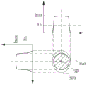
Although shown in fig. 2 and 5 in a simplified manner, the beam of the pulsed laser light P L in the case of using the transfer lens 48 is precisely as shown in fig. 11 and 12, that is, the beam of the pulsed laser light P L emitted from the window 42 first converges at the converging point CP and then diverges and connects the transferred image at the transfer position FP.
Fig. 11 shows an example in which the depth Δ Zsf is 0mm and the transfer position FP coincides with the surface 41a of the workpiece 41. In the case of fig. 11, in the case where the light intensity ratio R at the transfer position FP is about 1, the target fluence Ft at the transfer position FP almost coincides with the maximum fluence Fsfp on the surface 41 a.
In contrast, FIG. 12 is an example in which the depth Δ Zsf is, for example, 1mm, and the transfer position FP is inside from the surface 41 a. in the case of FIG. 12, even if the light intensity ratio R at the transfer position FP is about 1, the target fluence Ft at the transfer position FP does not coincide with the maximum fluence Fsfp on the surface 41 a. this is because the beam profile of the cross section SP of the beam changes in the optical axis direction of the pulse laser light P L. therefore, this is because, with respect to the maximum light intensity Imax, the maximum light intensity Imax at the transfer position FP as the reference position does not coincide with the maximum light intensity Imax at the surface 41a, and the light intensity ratio R changes.
FIG. 13 is data obtained by measuring the shape of the cross section SP of the beam and the light intensity distribution at each position in the optical axis direction of the pulse laser beam P L A distance Z L is the distance in the optical axis direction (Z axis direction) from the transfer position FP, and the direction from the transfer position FP to the window 42 and the transfer lens 48 is defined as positive.
In fig. 13, fig. 13E shows the shape and light intensity distribution of the cross section SP of the beam at the transfer position FP where Z L is 0, and the shape and light intensity distribution of the cross section SP of the beam at the position close to the window 42 are shown in the order of fig. 13D, 13C, 13B, and 13A, fig. 13D shows the cross section SP where the distance Z L is 0.5mm, fig. 13C shows the cross section SP where the distance Z L is 0.9mm, fig. 13B shows the cross section SP where the distance Z L is 1.1mm, and fig. 13A shows the cross section SP. where the distance Z L is 1.5mm, and fig. 13D to 13A are cross sections existing between the transfer position FP and the light converging point CP.
The light intensity distribution is represented by the change in the depth in the cross section SP, and the difference in the light intensity I is larger as the difference in depth is larger, and it is understood from fig. 13 that the difference in the concentration between the central portion and the periphery in the cross section SP at each distance Z L becomes larger as going from fig. 13E to fig. 13A.
In the transfer position FP shown in FIG. 13E, the shape of the cross section SP of the beam is a circle corresponding to the shape of the pinhole of the transfer mask 47, and the light intensity distribution in the cross section SP is a nearly flat top hat shape, and as shown in FIGS. 13E to 13A, the larger the distance Z L from the transfer position FP, the closer the shape of the cross section SP is to an ellipse, and the beam profile in the radial direction of the cross section SP is also to a Gaussian distribution in which the difference between the center and the periphery is large, and as a result, the beam profile of the cross section SP changes in the optical axis direction of the pulse laser light P L, and as a result, specifically, as shown in FIG. 14, the light intensity ratio R also changes corresponding to the distance Z L.
Fig. 14 is correlation data of the distance Z L and the light intensity ratio R generated from the measurement data shown in fig. 13, and the light intensity ratio R is a value indicating the magnitude of the maximum light intensity Imax at each position shown in fig. 13E to 13A with respect to the average light intensity Iavs at the transfer position FP shown in fig. 13E as the reference position, as described above.
At the transfer position FP, the beam profile of the cross section SP is of a top hat type, and therefore, as shown in the graph of fig. 14, the light intensity ratio R is about 1, and the light intensity ratio R becomes larger as the distance Z L is larger and becomes the light intensity ratio R of 1.5, 2, 2.5 at the distances Z L of 0.5mm, 1.0mm and 1.5mm, respectively, in a period from the transfer position FP toward the light converging point CP as the distance Z L is 0 to 1.5mm, which shows that the beam profile of the cross section SP becomes closer to a shape such as a gaussian distribution as the distance Z L is larger, and as a result, the maximum light intensity Imax at each distance Z L becomes larger with respect to the average light intensity Iavs of the transfer position FP.
Therefore, as shown in FIG. 11, in the case where the transfer position FP is set to the surface 41a, if the beam profile is, for example, a top hat type as shown in FIG. 8, the target fluence Ft at the transfer position FP substantially coincides with the maximum fluence Fsfp on the surface 41a, however, as shown in FIG. 12, in the case where the transfer position FP is set to a position entering from the surface 41a, the maximum fluence Fsfp on the surface 41a represents a value larger than the target fluence Ft at the transfer position FP in accordance with the relationship between the distance Z L and the light intensity ratio R shown in FIG. 14.
Here, the maximum fluence Fsfp on the surface 41a of the workpiece 41 can be obtained from the light intensity ratio R and the target fluence Ft at the transfer position FP by the following equation.
Fsfp=R·Ft……(5)
For example, at the distance Z L of 1.0mm, the light intensity ratio R of 2 means that the maximum light intensity Imax at the position where the distance Z L of 1.0mm is 2 times the average light intensity Iavs at the transfer position FP, and therefore, the maximum fluence Fsfp at the distance Z L of 1.0mm becomes 2 times the target fluence Ft with respect to the target fluence Ft with the average light intensity Iavs at the transfer position FP as a reference.
When the relationship between the maximum fluence Fsfp and the target fluence Ft and the experimental results shown in fig. 15 to 20 below are examined, the following results are obtained: the maximum fluence Fsfp on the surface 41a of the workpiece 41 is related to the crack CR.
Fig. 15 is a graph showing the relationship between the target fluence Ft and the processing depth Δ Zd at the transfer position FP. The horizontal axis represents the target fluence Ft and the vertical axis represents the machining depth Δ Zd. The irradiation conditions in fig. 15 are that the diameter Di of the cross section SP of the beam at the transfer position FP is 55 μm, the repetition frequency f is 1kHz, the number N of irradiation pulses is 5000 pulses, and the irradiation time is 5 sec. Further, in the example of fig. 15, the depth Δ Zfs is 0, and as shown in fig. 11, the transfer position FP coincides with the surface 41 a.
In the example of FIG. 15, the target fluence Ft is set to be from 5J/cm2Change to 30J/cm2. As can be seen from the graph of FIG. 15, the target fluence Ft is 10J/cm2To 30J/cm2In the range of (1), hole processing with a high aspect ratio is performed with a processing depth Δ Zd of 1mm or more. In the range of the target fluence Ft, no crack CR is generated.
In fig. 16, a graph having a depth Δ Zfs of 0.5mm is added in addition to the same graph having a depth Δ Zfs of 0 as shown in fig. 15. The graph with the depth Δ Zfs being 0 is represented by diamonds and the graph with the depth Δ Zfs being 0.5mm is represented by squares. Other irradiation conditions were the same as in fig. 15.
As shown in fig. 16, at a depth Δ Zfs of 0.5mm, the target fluence Ft is also 10J/cm2To 30J/cm2In the range of (1), hole processing with a high aspect ratio is performed with a processing depth Δ Zd of 1mm or more. However, in the case where the depth Δ Zfs is 0.5mm, the target fluence Ft is 25J/cm2No cracks CR occurred until now, but at 30J/cm indicated by a circle2At this point, a crack CR is generated.
FIG. 17 is a view showing that the target fluence Ft is set to 30J/cm2In the case of (3), photographs of the state of each hole H were taken when the hole was formed with the depth Δ Zfs set to 0mm and when the hole was formed with the depth Δ Zfs set to 0.5 mm. As shown in fig. 17, the following can be known: when the depth Δ Zfs was 0mm, no crack CR was generated, but when the depth Δ Zfs was 0.5mm, a crack CR was generated.
In the case where the depth Δ Zfs is 0mm, the distance Z L is 0mm, and therefore, according to the graph of fig. 14, the light intensity ratio R is about 1, and therefore, the target fluence Ft at the transfer position FP is 30J/cm2In the case of (2), the maximum fluence Fsfp is also about 30J/cm2In contrast, in the case where the depth Δ Zfs is 0.5mm, the distance Z L is 0.5mm, and therefore, according to the graph of fig. 14, the light intensity ratio R is about 1.52The maximum fluence Fsfp is also about 45J/cm2。
Fig. 18 and 19 also show graphs of the same experimental results as fig. 16. In fig. 18 and 19, as in fig. 16, the graph of fig. 15 is inserted so as to be comparable to the graph of fig. 15.
Fig. 18 shows an example in which the depth Δ Zfs is set to 1mm, and in fig. 18, plotted points are indicated by triangles in a graph in which the depth Δ Zfs is 1 mm. In fig. 18, the graph in which the plotted points are rhombuses is the same graph as fig. 15 in which the depth Δ zfs is 0 mm. Fig. 19 shows an example in which the depth Δ Zfs is 1.5mm, and in fig. 19, plotted points are indicated by a mark in a graph in which the depth Δ Zfs is 1.5 mm. In fig. 19, the graph in which the plotted points are rhomboid is also the same graph as in fig. 15 in which the depth Δ zfs is 0 mm. In fig. 18 and 19, the irradiation conditions other than the depth Δ Zfs are the same as in the example of fig. 15.
As shown in fig. 18 and 19, the target fluence Ft is from 10J/cm at the depth Δ Zfs of 0.5mm2To 30J/cm2In the range of (1), hole processing with a high aspect ratio is performed with a processing depth Δ Zd of 1mm or more.
However, in FIGS. 18 and 19, as shown by the round frame, the target fluence Ft is 20J/cm2To 30J/cm2Within the range of (c), cracks CR are generated.
In the case where the depth Δ Zfs is 1mm, the distance Z L is 1mm, and therefore, according to the graph of fig. 14, the light intensity ratio R is about 2, and therefore, the target fluence Ft at the transfer position FP is 20J/cm2In the case of (2), the maximum fluence Fsfp is about 40J/cm2. Also, at the target fluence Ft of 30J/cm2In the case of (2), the maximum fluence Fsfp is about 60J/cm2。
Further, in the case where the depth Δ Zfs is 1.5mm, the distance Z L is 1.5, and therefore, according to the graph of fig. 14, the light intensity ratio R is about 2.5, and therefore, even if the target fluence Ft of the transfer position FP is 20J/cm2The maximum fluence Fsfp is also about 50J/cm2. Also, at the target fluence Ft of 30J/cm2In the case of (2), the maximum fluence Fsfp is about 75J/cm2。
FIG. 20 is a view showing that the target fluence Ft is set to 20J/cm2In the case of (1), the photographs of the state of each hole H in fig. 18 were taken when the hole was formed with the depth Δ Zfs set to 1mm, and in fig. 19, the hole was formed with the depth Δ Zfs set to 1.5 mm. As shown in fig. 20, the following can be known: in both the case where the depth Δ Zfs was 1mm and the case where the depth Δ Zfs was 1.5mm, cracks CR were generated.
Fig. 21 shows a table summarizing the experimental results of fig. 15 to 19. In fig. 21, the data of condition 1-1 to condition 1-3 are data corresponding to the experimental results shown in the graph of fig. 15. That is, the data of the condition 1-1 to the condition 1-3 is set to the depth Δ Zfs to 0 and the target fluence Ft is dividedRespectively set to 10J/cm2、20J/cm2、30J/cm2And the experimental results in the case of performing hole machining.
Also, in fig. 21, the data of condition 2-1 to condition 2-3 are data corresponding to the experimental results shown in the graph of fig. 16. That is, the data of the condition 2-1 to the condition 2-3 were set to the depth Δ Zfs of 0.5mm and the target fluence Ft was set to 10J/cm, respectively2、20J/cm2、30J/cm2And the experimental results in the case of performing hole machining.
Also, in fig. 21, the data of condition 3-1 to condition 3-3 are data corresponding to the experimental results shown in the graph of fig. 18. That is, the data of the condition 3-1 to the condition 3-3 are set to the depth Δ Zfs of 1mm and the target fluence Ft is set to 10J/cm, respectively2、20J/cm2、30J/cm2And the experimental results in the case of performing hole machining.
Also, in fig. 21, the data of condition 4-1 to condition 4-3 are data corresponding to the experimental results shown in the graph of fig. 19. That is, the data of the condition 4-1 to the condition 4-3 were set to the depth Δ Zfs of 1.5mm and the target fluence Ft was set to 10J/cm, respectively2、20J/cm2、30J/cm2And the experimental results in the case of performing hole machining.
As can be seen from FIG. 21, the maximum fluence Fsfp on the surface 41a is 40J/cm as shown by the conditions in which the cells are grayed out, such as conditions 2-3, 3-2, 3-3, 4-2, and 4-32In the above case, the crack CR is generated. The inventors found from the results of such experiments that the maximum fluence Fsfp was considered to be the cause of the crack CR.
4. Laser processing system and laser processing method according to embodiment 1
4.1 Structure
Fig. 22 schematically shows the structure of a laser processing system 2A according to embodiment 1. The laser processing system 2A according to embodiment 1 includes a laser processing apparatus 4A instead of the laser processing apparatus 4 of the laser processing system 2 according to the comparative example described with reference to fig. 1. In the following description of embodiment 1, differences in the laser processing system 2 of the comparative example will be mainly described, and the same components will be denoted by the same reference numerals and will not be described.
Unlike the laser processing apparatus 4 of the comparative example, the laser processing apparatus 4A of embodiment 1 includes a laser processing control unit 32A instead of the laser processing control unit 32. The other configuration of the laser processing apparatus 4A is the same as that of the laser processing apparatus 4 of the comparative example.
The laser processing control unit 32A differs from the laser processing control unit 32 of the comparative example in that the following processing is added: before laser processing, it is determined whether or not the maximum fluence Fsfp on the surface 41a of the object 41 is within a predetermined range, based on the target fluence Ft at the transfer position FP set as the irradiation condition. The other points are the same as those of the laser processing control unit 32A.
4.2 actions
The operation of the laser processing system 2A will be described with reference to fig. 23 and 24. The flowchart of fig. 23 of embodiment 1 differs from the flowchart of fig. 3 of the comparative example in that steps S1410 and S1420 are added between step S1400 and step S1500. The point of addition of S1900 is different. The other aspects are the same.
As in the comparative example, the laser processing control unit 32A according to embodiment 1 executes the processes of S1100 to S1400. Then, the processes of S1410 and S1420 are executed. S1410 is a process of evaluating the maximum fluence Fsfp on the surface 41a of the workpiece 41. S1420 determines whether or not the maximum fluence Fsfp is within the allowable range based on the evaluation result at S1410. The data of the allowable range is stored in advance in, for example, a memory or an external storage device in the laser processing control unit 32A. If it is determined in S1420 that the maximum fluence Fsfp is within the allowable range (yes in S1420), the laser processing control unit 32A proceeds to S1500. The subsequent processing was the same as in the comparative example.
In this way, the laser processing control unit 32A functions as a determination unit that determines whether or not the maximum fluence Fsfp of the pulse laser light P L on the front surface 41a of the workpiece 41, which is a transparent material, is within a predetermined allowable range, and the laser processing control unit 32A functions as a control unit that allows irradiation of the pulse laser light P L when it is determined that the maximum fluence Fsfp is within the predetermined allowable range.
On the other hand, if it is determined in S1420 that the maximum fluence Fsfp is outside the allowable range (yes in S1420), the laser processing control unit 32A proceeds to S1900 and gives a warning. The content of the warning is as follows: since there is a possibility that the crack CR is generated under the set irradiation condition, it is notified that the laser processing is not possible. The laser processing control unit 32A controls a display, not shown, to notify the user of such a message during the warning process. Alternatively, the speaker may be controlled to notify the message by sound. Further, instead of or in addition to the display and the speaker of the laser processing system 2A, a warning message may be notified to a plant management system that manages the inside of the plant.
Fig. 24 is a flowchart of a processing procedure for evaluating the maximum fluence Fsfp at S1410, the laser processing control unit 32A reads out the value of the depth Δ Zsf from the data of the irradiation conditions, and sets Δ Zsf read out in the memory as the distance Z L (S1411), the laser processing control unit 32A reads out the light intensity ratio R corresponding to the irradiation conditions from the correlation data of the distance Z L and the light intensity ratio R shown in fig. 14 at S1412, and specifically, reads out the light intensity ratio R corresponding to the distance Z L set as the value of the depth Δ Zsf at S1411 (S1412).
The correlation data shown in fig. 14 is stored in advance in the memory of the laser processing control unit 32A or an external storage device. The correlation data may be recorded in the form of a table or a function.
The laser processing control portion 32A calculates the maximum fluence Fsfp on the surface 41a of the object 41 based on the above-described expression (5) from the target fluence Ft at the transfer position FP based on the read light intensity ratio R (S1413).
When it is determined in S1414 that the maximum fluence Fsfp is within the allowable range, the laser processing control unit 32A records "0" as the evaluation result in the flag FRG (S1415). When it is determined in S1414 that the maximum fluence Fsfp is outside the allowable range, the laser processing control unit 32A records "1" as the evaluation result in the flag FRG (S1416). Then, the laser processing control unit 32A returns to the main routine shown in fig. 23 and executes S1420.
4.3 action
As described above, when the maximum fluence Fsfp is determined to be within the allowable range in the laser processing of performing the hole processing with a high aspect ratio by irradiating the pulsed laser light P L, the laser processing system 2A according to embodiment 1 allows irradiation of the pulsed laser light, and therefore, generation of the crack CR can be suppressed.
When the maximum fluence Fsfp is determined to be outside the allowable range, the laser processing system 2A warns. Therefore, the user can reliably grasp that the irradiation condition is inappropriate. When the maximum fluence Fsfp is determined to be outside the allowable range, the laser processing system 2A prohibits the laser processing. Therefore, the occurrence of the crack CR can be prevented.
When the maximum fluence Fsfp is determined to be outside the allowable range, the laser processing control unit 32A may automatically change the irradiation conditions to appropriate conditions under which the crack CR is not likely to occur, and perform the laser processing.
4.4 preferred processing conditions
4.4.1 pulse Width of pulsed laser
In the case of using a pulsed laser of ultraviolet light, a nanosecond-level pulsed laser having a pulse width of 1ns to 100ns in the full width at half maximum is preferably used. This is because the pulse width is determined according to the performance of the laser device 3, but it is difficult to manufacture the laser device 3 capable of outputting a pulse laser having a pulse energy with a pulse width on the order of picoseconds as a pulse laser of ultraviolet rays at the present time. By using a pulse laser of nanosecond-order ultraviolet rays as in this example, the laser device 3 that can be easily purchased at the present time can be used.
The pulse width is preferably 1ns to 100ns, more preferably 10ns to 20ns in the full width at half maximum. As the laser device 3, such a laser device 3 that outputs a pulse laser beam having a pulse width is preferably used.
Preferred processing conditions for processing a hole having a high aspect ratio in a workpiece 41, which is a transparent material transparent to ultraviolet light such as synthetic quartz glass, using such nanosecond-level ultraviolet pulsed laser light are as follows.
4.4.2 range of diameter Di of the beam
The range of the diameter Di of the beam at the transfer position FP of the pulse laser light P L is preferably 10 μm or more and 150 μm or less because, in the case of the pulse laser light P L using ultraviolet rays, a phenomenon as shown in fig. 5 occurs when the diameter Di ranges from 10 μm or more to 150 μm or less because such a phenomenon is a precondition for realizing hole processing with a high aspect ratio.
4.4.3 preferable conditions in the case where the workpiece 41 is a synthetic quartz glass
4.4.3.1 wavelength of pulse laser
When the synthetic quartz glass is subjected to hole processing, the center wavelength of the pulsed laser is preferably 157.6nm to 248.7 nm. In particular, as the pulse laser, ArF laser having a center wavelength of about 193.4nm is preferable.
4.4.3.2 depth Δ Zsf
The depth Δ Zsf is preferably in the range of 0mm to 4 mm. As is clear from the experimental results, the machining depth Δ Zd increases as the depth Δ Zsf increases to a fixed value. However, when the depth Δ Zsf exceeds about 4mm, the machining depth Δ Zd greatly interrupts by 1mm, and high aspect ratio hole machining cannot be performed. This is considered to be because, when the transfer position FP is too deep, the fluence in the vicinity of the surface 41a of the workpiece 41 is insufficient, and the ablation process in the vicinity of the surface cannot progress, and as a result, the ablation process does not proceed in the depth direction.
4.4.3.3 range of target fluence Ft
The target fluence Ft is preferably 5J/cm2Above and 30J/cm2The following. It can be seen that if the target fluence Ft is less than 5J/cm2Then, the high aspect ratio hole processing as shown in fig. 5 cannot be performed. That is, the lower limit of the preferable range of the target fluence Ft is 5J/cm2. Further, as shown in fig. 16 to 21, when the depth Δ Zfs at the transfer position FP is in the range of 0.5mm or more and 1.5mm or less, the target fluence Ft exceeds 30J/cm2In this case, the crack CR may be generated. Accordingly, the object is notedThe upper limit value of the preferable range of the amount Ft is 30J/cm2。
4.4.3.4 allowable range of maximum fluence Fsfp
The allowable range of the maximum fluence Fsfp is preferably 10J/cm based on the experimental results shown in FIGS. 15 to 212Above 40J/cm2The following. According to the following feature that, within the allowable range, the lower limit is 10J/cm2The lower limit value of the target fluence Ft required for hole processing with high aspect ratio is 5J/cm2。
As shown in the graph of FIG. 14, the maximum value of the light intensity ratio R is 2 or more depending on the value of the distance Z L, and therefore, when the lower limit value of the target fluence Ft is 5J/cm2When the light intensity ratio R is multiplied by "2" as a value obtained by estimating the maximum value of the light intensity ratio R less, 10J/cm is obtained2. That is, in order to realize a hole with a high aspect ratio, the target fluence Ft needs to be as low as 5J/cm2When the light intensity ratio is 2 or more, the maximum fluence Fsfp is 10J/cm2The above. The lower limit of the maximum fluence Fsfp is 10J/cm2。
On the other hand, as shown in FIG. 21, when the maximum fluence Fsfp exceeds 40J/cm2When the crack CR is generated. Therefore, it is preferably 40J/cm which is the upper limit of the allowable range2。
4.4.3.5 irradiation pulse number N range
Fig. 25 is a graph showing the relationship between the number of irradiation pulses N and the machining depth Δ Zd. All of the 6 graphs shown in fig. 25 are graphs in the case where the depth Δ Zdsf of the transfer position FP is 0.5 mm. The graphs differ in the values of the target fluence Ft and the maximum fluence Fsfp. Fig. 25 shows how the machining depth Δ Zd changes when the number of irradiation pulses N is changed from 5,000 pulses to 30,000 pulses. As other irradiation conditions common to the graphs, the irradiation time was 5sec to 30sec, the diameter Di of the cross section SP of the beam was 55 μm, and the repetition frequency f was 1 kHz.
In fig. 25, the graph with the plotted points being rhomboid is such that the target fluence Ft is 5.1J/cm2And the maximum fluence of Fsfp is 7.5J/cm2Graph in the case of (1). Drawing (painting)The curve plot with the square point is that the target fluence Ft is 10.1J/cm2And the maximum fluence Fsfp is 15J/cm2Graph in the case of (1). The curve with the triangle-shaped drawing points is that the target fluence Ft is 15.2J/cm2And the maximum fluence Fsfp is 22.5J/cm2Graph in the case of (1).
The graph with the point marked × is plotted such that the target fluence Ft is 20.2J/cm2And the maximum fluence Fsfp is 30J/cm2Graph in the case of (1). The graph with plotted points marked with x is that the target fluence Ft is 25.3J/cm2And the maximum fluence Fsfp is 37.5J/cm2Graph in the case of (1). The graph with the point marked as a circle is plotted such that the target fluence Ft is 30.3J/cm2And the maximum fluence Fsfp is 45J/cm2Graph in the case of (1).
As shown in FIG. 25, in the region where the number of irradiation pulses N is from 5,000 pulses to 20,000 pulses, the target fluence Ft is made to be from about 5J/cm2Increases to about 25J/cm2At this time, the processing depth Δ ZD increases from about 1mm (1,000 μm) to about 5mm (5,000 μm). Further, the machining depth Δ Zd is saturated when the number of irradiation pulses N is 20,000 pulses, and does not increase even if the number of irradiation pulses N is further increased.
Further, in the region where the number of irradiation pulses N is 5,000 to 20,000 pulses, hole machining with a machining depth Δ Zd of 5mm (5,000 μm) at most can be performed. The diameter Di of the cross section SP of the beam having an aspect ratio of 5mm (5,000 μm) as the maximum value of the machining depth Δ Zd is 55 μm, and therefore, 5,000 μm/55 μm is about 90. In the region where the number of irradiation pulses N is 5,000 pulses to 20,000 pulses, high aspect ratio hole machining of about 90 at maximum can be performed. In summary, the number of irradiation pulses N is preferably in the range of 5,000 pulses to 20,000 pulses.
4.5 others
In this example, the workpiece 41 is moved by controlling the XYZ stage 34, and the transfer position FP of the pulse laser light P L and the workpiece 41 are relatively positioned, and instead of moving the workpiece 41 in the optical axis direction of the pulse laser light, the transfer mask 47 may be moved in the optical axis direction of the pulse laser light, that is, the transfer position of the transferred image is also changed in the optical axis direction by moving the transfer mask 47 in the optical axis direction of the pulse laser light P L by changing only the position on the object side of the transferred image transferred by the transfer lens 48 with respect to the transfer lens 48, and thus the transfer position FP of the pulse laser light P L and the workpiece 41 can be relatively positioned.
Further, in the case where the pinhole-shaped transfer image is transferred to the workpiece 41 using the transfer optical system as in this example, there is an advantage that the change in the diameter of the beam can be suppressed as compared with the case where the pulsed laser light is simply condensed and irradiated to the workpiece 41 as in embodiment 2 described later. The beam of the pulse laser light output from the laser device 3 changes its diameter due to a change in mode in a state of an optical resonator or the like of the laser device 3. On the other hand, in the case of using a transfer optical system, a pinhole-shaped transfer image of the pulse laser beam is formed through the transfer mask 47 without directly irradiating the object 41 with the beam of the pulse laser beam, and the formed transfer image is transferred to the object 41. Therefore, variation in the diameter of the beam due to mode variation of the pulsed laser can be suppressed.
In this example, an ArF excimer laser apparatus that uses an ArF laser gas as a laser medium and outputs a pulse laser beam having a center wavelength of about 193.4nm was described as an example of the laser apparatus 3, but other laser apparatuses are also possible. As the laser device 3, a KrF excimer laser device which uses KrF laser gas as a laser medium and outputs a pulse laser having a center wavelength of about 248.4nm may be used. When synthetic quartz glass is used as the workpiece 41, the central wavelength of the pulsed laser light is preferably in the range from F2The central wavelength of the laser is about 157.6nm to KThe center wavelength of the rF laser is in the range of 248.4 mn.
The workpiece 41 is made of synthetic quartz glass, but the synthetic quartz glass is not limited thereto, and the workpiece 41 may be made of a transparent material transparent to the ultraviolet pulsed laser beam. For example, MgF exists as a transparent material transparent to a pulsed laser beam of ultraviolet rays2Crystal, CaF2Crystals, sapphire, quartz, and the like.
5. Laser processing system and laser processing method according to embodiment 2
5.1 Structure
Fig. 26 shows a laser processing system 2B of embodiment 2. As shown in fig. 26, a laser processing system 2B according to embodiment 2 includes a laser device 3 and a laser processing device 4B. The laser device 3 is the same as embodiment 1. The laser processing apparatus 4B includes an optical system 61 instead of the optical system 36 of the laser processing apparatus 4A according to embodiment 1. The optical system 61 is an optical system as follows: unlike the optical system 36 of embodiment 1, which includes the transfer mask 47 and the transfer lens 48, the optical system includes a condensing optical system that directly condenses the beam of the pulsed laser beam having the gaussian distribution output from the laser device 3 and irradiates the condensed beam onto the workpiece 41.
The laser processing control unit 32B performs relative positioning of the transfer position of the pulse laser light and the workpiece 41 instead of performing relative positioning of the beam waist position BW of the pulse laser light P L and the workpiece 41 as in the laser processing control unit 32A of embodiment 1, the depth Δ Zsfw in embodiment 2 is not the depth Δ Zsf of the transfer position FP but the depth of the beam waist position, the target fluence Ftw in embodiment 2 is not the target fluence Ft at the transfer position FP but the target fluence at the beam waist position BW, and the laser processing control unit 32B determines whether or not the maximum fluence Fsfp on the surface 41a of the workpiece 41 is within the allowable range based on the target fluence Ftw at the beam waist position BW.
The other configuration of the laser processing system 2B is the same as that of the laser processing system 2A according to embodiment 1, and therefore, the following description will focus on differences.
The optical system 61 has high mirrors 36a to 36c, an attenuator 52, and a condenser lens 62. The high reflection mirrors 36a to 36c and the attenuator 52 are the same as the optical system 36 of embodiment 1. The high reflection mirror 36c reflects the pulse laser light toward the condenser lens 62.
The condenser lens 62 is configured to condense the incident pulsed laser light to the workpiece 41 through the window 42.
Further, the laser processing system 2B of embodiment 2 also processes a hole having a high aspect ratio and a diameter of 10 μm or more and 150 μm or less in the workpiece 41, similarly to the laser processing system 2A of embodiment 1, and therefore, the laser processing system 2B also irradiates the workpiece 41 with a pulse laser beam having a beam diameter Dw of 10 μm or more and 150 μm or less in the beam waist position BW, and similarly to the diameter Di shown in fig. 9, the beam diameter Dw of the pulse laser beam P L in the beam waist position is 1/e of the maximum light intensity Imax in the beam profile2Width of the position of value of (1/e)2Full width.
In the case of the laser processing system 2B, unlike the laser processing system 2A, the workpiece 41 is irradiated with the pulse laser light P L having a gaussian distribution without converting the laser light into a transferred image, and therefore, the beam diameter of the pulse laser light P L is determined in accordance with the specification of the laser device 3.
When there is no optical loss of the optical system 36, the amount of fluence Fw at the beam waist position BW is determined by the following equation (6).
Fw=Et·T/{π(Dw/2)2}……(6)
Where T is the transmittance of the attenuator, Et is the pulse energy of the pulse laser light output from the laser device, and Dw is the diameter of the cross section SP of the beam at the beam waist position BW.
When there is no optical loss of the optical system 36, the transmittance T of the attenuator is determined by the above equations (6) to (7).
T=π(Dw/2)2·Fw/Et……(7)
As shown in fig. 27, the beam of the pulse laser light P L of embodiment 2 is most contracted at the beam waist position BW after being emitted from the condenser lens 62 and then is diverged, the beam waist position BW of the diameter of the cross section SP of the beam is minimum, and in embodiment 2 using the condenser lens 62, as in embodiment 1 using the transfer lens 48, there is no condensing point CP between the condenser lens 62 and the workpiece 41 (see fig. 12).
Therefore, as shown in fig. 27, even in the case where the beam waist position BW is made to enter the inside from the surface 41a, the diameter and the area of the cross section SP of the beam on the surface 41a are larger than those of the beam at the beam waist position BW.
Further, as shown in fig. 28, when the beam profile at the beam waist position BW is compared with the beam profile on the surface 41a, it is gaussian distribution. Furthermore, the maximum light intensity Imax1 at the beam waist position BW is greater than the maximum light intensity Imax2 on the surface 41 a.
Therefore, in embodiment 2, when the value of the distance Z L corresponding to embodiment 1 is set to be the distance Z L w from the beam waist position BW to the front surface 41a, the relationship between the light intensity ratio Rw and the distance Z L w is as shown in fig. 29.
Here, the light intensity ratio Rw is a light intensity ratio in the case where the pulsed laser light P L is condensed by the condensing lens 42 and irradiated to the workpiece 41 as in embodiment 2, that is, a light intensity ratio in the case where the beam profile at the beam waist position BW is close to gaussian distribution, and can be obtained from the following equation (8).
Rw=Imax/Iavw……(8)
Where Iavw is the average light intensity at the beam waist position BW, and the average light intensity Imax is the maximum light intensity Imax at each position located at a distance Z L w from the beam waist position BW.
The maximum fluence Fsfp on the surface 41a of the workpiece 41 can be obtained from the light intensity ratio Rw and the target fluence Ft at the transfer position FP by the following formula (9).
Fsfp=Rw·Ftw……(9)
In fig. 29, the light intensity ratio Rw is the largest when the distance Z L w is 0, that is, when the beam waist position BW coincides with the surface 41a, and the larger the distance Z L w is, the smaller the light intensity ratio Rw is.
In embodiment 2, the laser processing control unit 32B determines whether or not the maximum fluence Fsfp on the surface 41a of the workpiece 41 is within the allowable range using the data of the correlation between the distance Z L w and the light intensity ratio Rw shown in fig. 29.
5.2 actions
The operation of the laser processing system 2B will be described with reference to fig. 30 to 32. The flowchart of fig. 30 of embodiment 2 differs from the flowchart of fig. 23 of embodiment 1 in that step S1400 is changed to step S1400B, step S1410 is changed to step S1410B, and S1500 and S1600 are changed to S1500B and S1600B, respectively. The other aspects are the same. After executing S1100 to S1300, the laser processing control unit 32B executes S1400B.
In S1400B, the laser processing control unit 32B acquires the irradiation conditions of the pulse laser beam. In S1400B, the irradiation conditions include the target fluence Ftw at the beam waist position BW, the depth Δ Zfsw of the beam waist position BW, the number N of irradiation pulses, and the repetition frequency f.
S1410B is a process of evaluating the maximum fluence Fsfp on the surface 41a of the workpiece 41. S1420 is a process of determining whether or not the maximum fluence Fsfp is within the allowable range based on the evaluation result of S1410B. If it is determined in S1420 that the maximum fluence Fsfp is within the allowable range (yes in S1420), the laser processing control unit 32B proceeds to S1500B. Then, the laser processing control unit 32B executes the process of S1600B. The subsequent processes in the main flowchart are the same as those in embodiment 1.
Fig. 32 is a flowchart showing a procedure of evaluating the maximum fluence Fsfp in S1410B, and the difference from fig. 24 of embodiment 1 is that S1411 to S1413 are changed to S1411B to S1413B in S1411B, the laser processing control unit 32B reads the value of the depth Δ Zsfw from the data of the irradiation conditions, sets the read Δ Zsfw as the distance Z L w, and the laser processing control unit 32A reads the light intensity ratio Rw. corresponding to the irradiation conditions, specifically, the light intensity ratio Rw corresponding to the distance Z L w in S1412B from the correlation data of the distance Z L w and the light intensity ratio Rw shown in fig. 29, and reads the light intensity ratio Rw corresponding to the distance Z L w for which the value of the depth Δ Zsfw is set in S1411B (S1412B).
The laser processing control unit 32B calculates the maximum fluence Fsfp on the surface 41a of the workpiece 41 from the target fluence Ftw at the beam waist position BW based on the read light intensity ratio Rw and on the above-described expression (9) (S1413B). In the subroutine of fig. 31, the subsequent processing is the same as in embodiment 1.
Fig. 32 shows the processing procedure of the laser processing of S1600B, the difference between fig. 32 and fig. 4 of the comparative example is that S1604 is changed to S1604b, in S1604B, the laser processing controller 32B sets the transmittance t of the attenuator 52 so that the fluence Fw at the beam waist position BW of the pulse laser light P L becomes the target fluence Ftw of the irradiation conditions, and the other processing is the same as fig. 4.
5.3 action
Similarly to embodiment 1, when the maximum fluence Fsfp is determined to be within the allowable range, the laser processing system 2B of embodiment 2 allows irradiation of the pulse laser beam, and therefore can suppress the occurrence of the crack CR, and further, compared to embodiment 1 using the transfer lens 48, the use efficiency of the pulse laser beam P L of embodiment 2 using the condensing optical system is higher, and therefore, in embodiment 2, when hole processing of the same size is performed on the same material, the pulse energy of the pulse laser beam P L output from the laser device 3 can be reduced compared to embodiment 1, and in embodiment 2, other operational effects and preferable processing conditions are also the same as those of embodiment 1.
5.4 others
The resonator of the laser device 3 may be a fabry-perot type resonator or an unstable resonator, which is a resonator in which a part of the reflecting surface of the output coupling mirror 27 is formed of a convex surface and a high reflecting surface of the rear view mirror 26 is formed of a concave surface, by employing such an unstable resonator, the diameter Dw of the beam waist position BW of the pulse laser light P L can be reduced, and the fluence at the beam waist position BW can be increased.
6. Laser processing system and laser processing method according to embodiment 3
6.1 Structure
Fig. 33 shows a laser processing system 2C of embodiment 3. As shown in fig. 33, a laser processing system 2C according to embodiment 3 includes a laser device 3 and a laser processing device 4C. The laser device 3 is the same as embodiment 1. The laser processing apparatus 4C includes a beam analyzer 81 instead of the laser processing apparatus 4A according to embodiment 1.
The laser processing apparatus 4C has a laser processing control unit 32C instead of the laser processing control unit 32A of the laser processing apparatus 4A, and the laser processing control unit 32C has a function of controlling the beam analyzer 81 instead of the laser processing control unit 32A to acquire data indicating a correlation between the distance Z L and the light intensity ratio R shown in fig. 14, and other points are the same as those of embodiment 1 in embodiment 3, and a description will be given centering on differences.
As shown in fig. 33, a beam analyzer 81 is provided at an end of the table 33. The beam analyzer 81 has an image sensor 81a, a holder 81b, and a single-axis stage 81 c. An image sensor 81a is mounted on one end of the holder 81b, and the other end is mounted on a single-axis stage 81 c.
The uniaxial stage 81c moves the image sensor 81a in the Y-axis direction, specifically, the uniaxial stage 81c moves between an insertion position at which the image sensor 81a is inserted into the position of the optical axis of the pulsed laser light P L emitted from the transfer lens 48, and a retracted position retracted from the insertion position, the retracted position being a position at which there is no obstacle to laser processing of the workpiece 41 on the table 33, the position of the image sensor 81a in the Z-axis direction can be adjusted by the XYZ stage 34, and although not shown, an ND filter, not shown, is provided in the beam analyzer 81, and the ND filter reduces the amount of pulsed laser light incident on the light receiving surface of the image sensor 81 a.
6.2 actions
The laser processing process of embodiment 3 is almost the same as that of fig. 23 and 24 in embodiment 1. The difference is that the processing of S1000 shown in fig. 34 is added before S1100 in the flowchart of fig. 23.
S1000 shown in fig. 34 is a process of acquiring data on the correlation between the distance Z L and the light intensity ratio R, and as shown in the flowchart of fig. 34, in S1010, the laser processing control unit 32C controls the single-axis stage 81C so as to insert the image sensor 81a of the beam analyzer 81 into the optical axis position of the pulsed laser light P L.
In S1015, the laser processing control unit 32C controls the XYZ stage 34 so that the position of the image sensor 81a in the Z-axis direction is aligned with the transfer position FP of the pulsed laser light, the position being a position where the distance Z L coincides with the light receiving surface of the image sensor 81a, and therefore, the laser processing control unit 32C sets the value of the distance Z L on the memory to an initial value "0".
Then, the laser processing control unit 32C transmits a control signal for performing laser oscillation under typical conditions to the laser control unit 13, thereby causing the laser device 3 to perform laser oscillation (S1020). Here, typical conditions are, for example, the nominal values of the laser device 3. Specific values include, for example, a target pulse energy Et in the range of 40mJ to 200mJ and a repetition frequency f in the range of 10Hz to 6 kHz. When the processing conditions during laser processing are assumed to be known at this time, the target pulse energy Et and the repetition frequency f that are defined as the processing conditions may be set to perform laser oscillation.
In S1030, the laser processing control unit 32C outputs the pulse laser light P L from the laser device 3, receives the pulse laser light P L by the image sensor 81a, measures the beam profile, calculates the maximum light intensity Imax and the average light intensity Iavs of the pulse laser light from the measured beam profile, then, the laser processing control unit 32C calculates the light intensity ratio R as Imax/Iavs (S1040) according to the above expression (4), and the laser processing control unit 32C records the value of the light intensity ratio R obtained by the calculation in the memory in association with the value of the distance Z L (S1045).
When the recording of the light intensity ratio R is completed, the laser processing control unit 32C moves the position of the image sensor 81a in the Z-axis direction upward by Δ ds (S1050). the laser processing control unit 32C adds Δ ds to the value of the distance Z L in the memory in accordance therewith to obtain the movement interval of the image sensor 81a in the Z-axis direction, that is, the laser processing control unit 32C measures the light intensity ratio R at intervals of Δ ds.
When the laser processing control unit 32C determines in S1055 whether the distance Z L exceeds the upper limit value Zmax, the value of the upper limit value Zmax is, for example, 1.5mm, and the distance Z L is equal to or less than the upper limit value Zmax (yes in S1055), the laser processing control unit 32C proceeds to S1070, and S1070 is a process of measuring the beam profile at the distance Z L set in S1050 and calculating the maximum light intensity Imax.
On the other hand, when the distance Z L exceeds the upper limit Zmax ("yes" in S1055), the laser processing control unit 32C ends the measurement and stops the laser oscillation (S1060), and then the laser processing control unit 32C moves the image sensor 81a of the beam analyzer 81 to the retracted position (S1065). the laser processing control unit 32C generates the correlation data between the distance Z L and the light intensity ratio R as shown in fig. 14, based on the recorded data of the light intensity ratio R at the Δ ds interval.
The laser processing control unit 32C stores the generated correlation data in a memory or an external storage device. The correlation data may be recorded in the form of a table, or may be recorded in the form of a function by obtaining an approximation formula from data of a plurality of light intensity ratios R recorded for each Δ ds. Further, the data may be interpolated from the light intensity ratio R recorded for each Δ ds. After the correlation data is acquired in this manner, the laser processing control unit 32C proceeds to S1100 in fig. 23. The subsequent processing is the same as in embodiment 1.
The flowchart of fig. 35 represents the processing procedure of the calculation of the maximum light intensity Imax and the average light intensity Iavs of S1030. The processing of S1030 is the same as that schematically described in fig. 8 to 10. In S1030, the average light intensity Iavs at the transfer position FP and the maximum light intensity Imax at the transfer position FP are calculated.
First, the laser processing control unit 32C performs measurement of the beam profile by the image sensor 81a (S1031). Next, from the light intensity I of each pixel PX of the image sensor 81, the maximum light intensity that is the maximum value is obtainedImax (S1032). Then, the laser processing control unit 32C calculates 1/e representing the maximum light intensity Imax based on the following formula (10)2The light intensity of the value of (b), i.e., the threshold value Ith (S1033).
Ith=Imax/e2……(10)
Finally, the laser processing control unit 32C calculates an average light intensity Iavs which is an average value of the light intensities I of the pixels PX having values equal to or greater than the threshold Ith (S1034).
The flowchart of fig. 36 shows the processing procedure of the calculation of the maximum light intensity Imax of S1070 in the processing of S1070, unlike the processing of S1030 shown in fig. 35, the maximum light intensity Imax at the position of the distance Z L after moving from the transfer position FP is calculated without calculating the average light intensity.
Therefore, the process of S1070 is the same as the step of the first half of fig. 35, and there is no step of calculating the average light intensity of the second half. That is, in S1071, the laser processing control unit 32C first measures the beam profile by the image sensor. Next, the maximum light intensity Imax is obtained as the maximum value from the light intensities I of the pixels PX of the image sensor 81 (S1072).
6.3 action
In embodiment 3, the beam analyzer 81 is used to actually measure the correlation data between the distance Z L and the light intensity ratio R before laser processing, and therefore, it is possible to obtain correlation data reflecting the individual differences of the laser processing system 2C, such as the characteristics of the optical system 36.
6.4 others
In this example, the pulse laser beam incident on the image sensor 81a is reduced by the ND filter. However, even when the ND filter is used, the amount of dimming is insufficient and the output signal of the image sensor 81a is saturated, the transmittance T of the attenuator 52 may be controlled to decrease the energy of the pulse laser beam incident on the image sensor 81 a. However, the transmittance T of the attenuator 52 is fixed while the correlation data is acquired. This is because, if the transmittance T varies during acquisition, accurate correlation data cannot be acquired.
Modification of 7 laser beam machining apparatus
7.1 modification 7-1
A laser processing apparatus 4D shown in fig. 37 is a modification of the laser processing apparatus 4B according to embodiment 2 shown in fig. 26. The laser processing apparatus 4D includes an optical system 71 instead of the optical system 61 of the laser processing apparatus 4B. Further, a laser processing control unit 32D is provided instead of the laser processing control unit 32B. The other structures are the same. Hereinafter, the following description will focus on the differences.
The optical system 71 includes a wavefront adjuster 72 added to the optical system 61. The wavefront modifier 72 has a concave lens 72a, a convex lens 72b, and a uniaxial stage 72 c. The uniaxial stage 72c holds the concave lens 72a, moves the concave lens 72a in the optical axis direction, and adjusts the interval between the concave lens 72a and the convex lens 72 b. The concave lens 72a and the convex lens 72b are disposed on the optical path of the pulse laser beam between the high reflection mirror 36c and the condenser lens 62. The pulse laser light reflected by the high reflection mirror 36c is incident on the condenser lens 62 via the concave lens 72a and the convex lens 72 b.
By adjusting the interval between the concave lens 72a and the convex lens 72b, the beam waist position of the pulse laser beam irradiated to the workpiece 41 can be changed.
The laser processing control unit 32D controls the XYZ stage 34 to adjust the position of the object 41 on the XY plane. On the other hand, with respect to the relative position between the beam waist position BW of the pulse laser beam and the workpiece 41 in the Z-axis direction, instead of moving the workpiece 41 on the XYZ stage 34, the single-axis stage 72c of the wavefront regulator 72 is controlled to adjust the position of the beam waist in the Z-axis direction. Specifically, the laser processing control unit 32D adjusts the interval between the concave lens 72a and the convex lens 72b by controlling the uniaxial stage 72c, and changes the wave surface of the pulse laser beam. By controlling the wave surface of the pulse laser, the beam waist position BW of the pulse laser can be adjusted.
7.2 modification 7-2
A laser processing system 2E shown in fig. 38 is obtained by changing the laser processing apparatus 4A of the laser processing system 2A according to embodiment 1 to a laser processing apparatus 4E. The laser processing apparatus 4E has a beam homogenizer 46. The beam equalizer 46 is disposed on the upstream side of the transfer mask 47 in the optical axis direction of the pulsed laser light. The homogenizer 46 has a fly-eye lens 46a and a condenser lens 46 b. The homogenizer 4 is disposed to homogenize the light intensity distribution of the pulse laser beam reflected by the high reflection mirror 36b, and performs kohler illumination on the transfer mask 47. The laser processing apparatus 4E includes a laser processing control unit 32E instead of the laser processing control unit 32A. The other structure is the same as embodiment 1.
The fly-eye lens 46a of the homogenizer 46 has a form in which a plurality of small lenses are two-dimensionally arrayed. Therefore, in the beam profile of the cross section SP of the beam on the upstream side of the transfer position FP where the transferred image is formed, a plurality of peaks may occur corresponding to the respective small lenses. Even in this case, at the transfer position FP, 1 top cap becomes 1 shape.
However, when the transfer position FP is moved inward from the surface 41a of the workpiece 41, the cross section SP of the beam at which a plurality of peaks occur may be close to the surface 41a on the upstream side of the transfer position FP. In this case, a plurality of peaks of fluence exist in the cross section SP of the beam on the surface 41 a. When there are a plurality of peaks of the fluence on the surface 41a, the laser processing control unit 32E determines the peak representing the maximum value among the peaks as the maximum fluence Fsfp. Then, the laser processing control unit 32E determines whether or not the maximum fluence Fsfp is within the allowable range. Other processes are the same as those in embodiment 1.
When the beam homogenizer 46 is used as in this example, the transfer mask 47 is irradiated with the pulse laser light having the uniform light intensity, and therefore, the light intensity distribution at the transfer position FP can be made uniform.
Further, as the transfer mask 47, a transfer mask in which a plurality of holes are formed may be used. In this case, a plurality of holes can be simultaneously processed in the workpiece 41.
8. Modification of laser device
In the above embodiments, the laser device can be variously modified. For example, the laser devices shown in fig. 39 and 40 may be used as the laser devices.
8.1 modification 1
The laser device 3D of modification 1 shown in fig. 39 is almost the same as the laser device 3 of embodiment 1 except that an amplifier 80 is added. The amplifier 80 is disposed on the optical path of the pulsed laser beam between the master oscillator 10 and the monitor module 11. The amplifier 80 is an amplifier that amplifies the energy of the pulse laser light output from the master oscillator 10.
The amplifier 80 has the same basic structure as the master oscillator 10, and has a laser cavity 21, a charger 23, and a Pulse Power Module (PPM)24 as the master oscillator 10.
Upon receiving the data of the target pulse energy Et received from the laser processing control unit 32A, the laser control unit 13D controls the charging voltage of the charger 23 to control the pulse energy.
Upon receiving the light emission trigger Tr from the laser processing control unit 32A, the laser control unit 13D causes the master oscillator 10 to perform laser oscillation. In addition, the amplifier 80 is controlled to operate in synchronization with the master oscillator 10. The laser control unit 13D opens the switch 24a of the pulse power module 24 of the amplifier 80 so that the pulse laser light output from the master oscillator 10 is discharged when entering the discharge space in the laser cavity 21 of the amplifier 80. As a result, the pulse laser beam incident on the amplifier 80 is amplified by the amplifier 80.
The pulse laser amplified and output by the amplifier 80 measures pulse energy by the monitor module 11. The laser control unit 13D controls the charging voltages of the respective chargers 23 of the amplifier 80 and the main oscillator 10 so that the measured values of the measured pulse energies approach the target pulse energy Et, respectively.
When the shutter 12 is opened, the pulsed laser light transmitted through the beam splitter 11a of the monitor module 11 enters the laser processing apparatus 4A shown in fig. 22.
By providing the amplifier 80 as in the laser device 3D, the pulse energy of the pulse laser can be increased.
8.2 modification 2
In the laser processing system, the laser device 3E of modification 2 shown in fig. 40 may be used. The laser device 3E has a master oscillator 83 and an amplifier 84. The laser device 3E includes a monitor module 11E instead of the monitor module 11.
The monitor module 11E is configured by adding a wavelength monitor 11c and a beam splitter 11d in addition to the monitor module 11 of embodiment 1.
In the monitor module 11E, the beam splitter 11d is disposed between the light sensor 11b and the reflected light path of the beam splitter 11 a. The beam splitter 11d reflects a part of the reflected light reflected by the beam splitter 11a and transmits the remaining part. The transmitted light transmitted through the beam splitter 11d enters the optical sensor 11b, and the reflected light reflected by the beam splitter 11d enters the wavelength monitor 11 c.
The wavelength monitor 11c is a well-known etalon beam splitter. The etalon beam splitter is configured by, for example, a diffusion plate, an air gap etalon, a condenser lens, and a line sensor. The etalon spectrometer generates an interference fringe of laser light to be incident through the diffusion plate and the air gap etalon, and the generated interference fringe is imaged on the light receiving surface of the line sensor through the condenser lens. Then, the interference fringe formed on the line sensor is measured, and the wavelength λ of the laser light is measured.
The master oscillator 83 is a solid-state laser device, and includes a semiconductor laser 86 that outputs seed light, a titanium sapphire amplifier 87 that amplifies the seed light, and a wavelength conversion system 88.
The semiconductor laser 86 is a distributed feedback type semiconductor laser that outputs CW (continuous wave) laser light having a wavelength of 773.6nm and oscillating continuously as seed light. By changing the temperature setting of the semiconductor laser 86, the oscillation wavelength can be changed.
The titanium sapphire amplifier 87 includes a titanium sapphire crystal (not shown) disposed on the optical path of the seed light, and a pumping pulse laser device (not shown) that outputs the 2 nd harmonic light of the Y L F laser light.
The wavelength conversion system 88 is a wavelength conversion system for generating the 4 th harmonic light, and includes L BO (L iB)3O5) Crystal and KBBF (KBe)2BO3F2) And (4) crystals. Each crystal is arranged on a rotary stage, not shown, and is configured to be capable of changing an incident angle of seed light with respect to each crystal.
Like the amplifier 80 shown in fig. 39, the amplifier 84 includes a pair of electrodes 22a and 22b, a laser cavity 21, the laser cavity 21 containing ArF laser gas as a laser medium, a pulse power module 24, and a charger 23. Further, the amplifier 84 has a convex mirror 91 and a concave mirror 92.
The convex mirror 91 and the concave mirror 92 are arranged so that the pulsed laser light output from the main oscillator 83 is reflected by the convex mirror 91 and the concave mirror 92, and the beam is amplified by 3 passes through the discharge space of the laser cavity 21.
Upon receiving the target wavelength λ t and the target pulse energy Et from the laser processing control unit 32A, the laser control unit 13E transmits the target wavelength λ t to the solid-state laser control unit 89 of the master oscillator 83. Further, laser control unit 13E sets the charging voltage of charger 23 of amplifier 84 so that the target pulse energy is obtained.
Upon receiving the target wavelength λ t from the laser controller 13E, the solid-state laser controller 89 changes the oscillation wavelength λ a1 of the semiconductor laser 86 so that the wavelength of the seed light output from the wavelength conversion system 88 becomes the target wavelength λ t, where λ a1 is set to be 4 times the target wavelength λ t, that is, λ a1 is 4 λ t and the target wavelength λ t is 193.4nm, and therefore λ a1 is 193.4 × 4 is 773.6nm, and where the amplifiable wavelength range of the amplifier 84 using ArF laser gas as the laser medium is 193.2nm to 193.6nm, and therefore the target wavelength λ t may be changed within this wavelength range as needed.
The solid-state laser control unit 89 controls a not-shown rotary stage to set the incidence angle of the laser light with respect to each crystal so that the wavelength conversion efficiency of the L BO crystal and the KBBF crystal becomes maximum in the wavelength conversion system 88.
When the emission trigger Tr is input from the laser controller 13E, the solid-state laser controller 89 transmits a trigger signal to the pumping pulse laser device of the titanium sapphire amplifier 87. In the titanium sapphire amplifier 87, the pumping pulse laser device converts a CW laser beam, which is an input seed light, into a pulse laser beam based on a trigger signal and outputs the pulse laser beam. The pulsed laser light output from the titanium sapphire amplifier 87 is input to a wavelength conversion system 88. The wavelength conversion system 88 converts the pulse laser beam of λ a1 into a pulse laser beam of the target wavelength λ t, which is the 4 th harmonic, and outputs the pulse laser beam.
When receiving the light emission trigger Tr from the laser processing control unit 32A, the laser control unit 13E opens the switch 24a of the pulse power module 24, and discharges the pulse laser light output from the master oscillator 83 when the pulse laser light enters the discharge space of the laser cavity 21 of the amplifier 84.
As a result, the pulse laser beam incident on the amplifier 84 from the main oscillator 83 is amplified in the laser cavity 21 by the action of the convex mirror 91 and the concave mirror 92 through a three-way path in the discharge space. Further, the diameter of the beam of the pulse laser is enlarged by the triplet.
The amplified pulse laser is sampled by the monitor module 11E, and actual measurement values of pulse energy and wavelength are measured. The laser control unit 13E controls the charging voltage of the charger 23 so that the difference between the measured pulse energy and the target pulse energy Et approaches 0. The laser control unit 13E controls the oscillation wavelength λ a1 of the semiconductor laser so that the difference between the measured wavelength and the target wavelength λ t is close to 0. When the shutter 12 is opened, the pulse laser light transmitted through the beam splitter 11a of the monitor module 11E is incident on the laser processing apparatus.
When the master oscillator 83 is a solid-state laser device, it is preferably applied as a light source of the laser processing device 4B shown in fig. 26 or the laser processing device 4D shown in fig. 37. The beam of the output pulse laser light is close to a gaussian beam in a single transverse mode, and therefore, the diameter of the beam at the beam waist position can be reduced to the vicinity of the diffraction boundary.
In this example, the amplifier 84 is an example of a multipass amplifier, but the amplifier is not limited to this, and may be an amplifier having a Fabry Perot (Fabry Perot) type resonator or a ring type resonator, for example.
In this example, a solid-state laser device is used as the master oscillator 83, and the laser device 3E is configured by combining the solid-state laser device with an amplifier 84 using ArF laser gas as a laser medium.
When the amplifier 84 is an amplifier using KrF laser gas as a laser medium, the amplifiable wavelength range is 248.1 nm-248.7 nm. As the laser device in this case, a wavelength-variable solid-state laser device capable of changing the wavelength in the above-described amplifiable wavelength range by the master oscillator 83 may be used, or a narrow-band KrF excimer laser device capable of narrowing the spectral line width may be used. In addition, the amplifier 84 is a mixer2In the case of using a laser gas as an amplifier of a laser medium, the amplification wavelength is 157.6 nm. In this case, as the laser device, for example, a solid-state laser device in which the main oscillator 83 oscillates in the wavelength band can be used. As described above, the wavelength of the ultraviolet pulse laser is preferably in the range of 157.6nm to 248.7nm from the viewpoint of an amplifier for amplifying the ultraviolet pulse laser.
The above description is not intended to be limiting, but is intended to be purely exemplary. Thus, it will be apparent to one skilled in the art that modifications can be made to the embodiments of the disclosure without departing from the claims set forth below.
The terms used in this specification and the appended claims should be construed as "non-limiting" terms throughout. For example, the terms "comprising" or "including" should be interpreted as "not being limited to what is described as" comprising ". The term "having" should be interpreted as "not limited to what is described as having". Furthermore, the modifier "1" recited in the specification and the appended claims should be construed as "at least 1" or "1 or more than 1".
Claims (20)
1. A laser processing method for performing laser processing on a transparent material transparent to ultraviolet rays by using a laser processing system, the laser processing system comprising: a laser device that outputs pulsed laser light of ultraviolet rays; a transfer mask having a transfer pattern formed thereon for transmitting the pulse laser beam; and a transfer optical system that transfers a transfer image formed by transmitting the pulsed laser light through the transfer pattern and having a shape corresponding to the transfer pattern, wherein the laser processing method includes:
A. a positioning step of performing relative positioning between a transfer position of the transfer image transferred by the transfer optical system and the transparent material in an optical axis direction of the pulsed laser light so that the transfer position is a position entering the transparent material from a surface of the transparent material at a predetermined depth Δ Zsf in the optical axis direction;
B. an irradiation condition acquisition step of acquiring an irradiation condition including a target fluence of the pulsed laser at the transfer position and the depth Δ Zsf;
C. a determination step of determining whether or not the maximum fluence of the pulsed laser on the surface of the transparent material is within the predetermined range, based on the irradiation conditions; and
D. a control step of allowing irradiation of the pulse laser beam when it is determined that the maximum fluence is within the predetermined range,
wherein the target fluence is an average fluence within a cross section of the beam at the transfer position in a direction perpendicular to an optical axis of the pulsed laser, and the maximum fluence is a maximum fluence among fluences of each of a plurality of small regions into which a cross section of the beam on the surface of the transparent material is divided after the division into the small regions.
2. The laser processing method according to claim 1, wherein the laser processing method further has the steps of:
E. and a warning step of warning when the maximum amount of attention is determined to be out of the predetermined range in the determination step.
3. The laser processing method according to claim 1,
the pulse width of the pulse laser is in the range of 1ns to 100ns, and the diameter of the beam at the transfer position is 10 [ mu ] m or more and 150 [ mu ] m or less.
4. The laser processing method according to claim 1,
the transparent material is synthetic quartz glass, and the wavelength of the pulse laser is 157.6 nm-248.7 nm.
5. The laser processing method according to claim 4,
the pulse laser is an ArF laser.
6. The laser processing method according to claim 5,
the depth Δ Zsf is in the range of 0mm to 4 mm.
7. The laser processing method according to claim 6,
the maximum fluence is 10J/cm2Above 40J/cm2The following.
8. The laser processing method according to claim 7,
a target fluence at the transfer position of the pulsed laser is 5J/cm2Above and 30J/cm2The following.
9. The laser processing method according to claim 5,
the number of irradiation pulses of the pulse laser is 5,000 pulses or more.
10. The laser processing method according to claim 9,
the number of irradiation pulses is 20,000 pulses or less.
11. A laser processing method for performing laser processing on a transparent material transparent to ultraviolet rays using a laser processing system, the laser processing system comprising: a laser device that outputs pulsed laser light of ultraviolet rays; and a condensing optical system that condenses the pulse laser light, wherein the laser processing method includes:
A. a positioning step of performing relative positioning between a beam waist position of the pulse laser and the transparent material in an optical axis direction of the pulse laser, wherein the positioning step is performed so that the beam waist position is a position entering the transparent material from a surface of the transparent material by a predetermined depth (Δ Zsfw) in the optical axis direction;
B. an irradiation condition acquisition step of acquiring an irradiation condition including a target fluence of the pulsed laser at the beam waist position and the depth Δ Zsf;
C. a determination step of determining whether or not the maximum fluence of the pulsed laser on the surface of the transparent material is within the predetermined range, based on the irradiation conditions; and
D. a control step of allowing irradiation of the pulse laser beam when it is determined that the maximum fluence is within the predetermined range,
wherein the target fluence is an average fluence in a cross-section of the beam at the beam waist position in a direction perpendicular to an optical axis of the pulsed laser, and the maximum fluence is a maximum fluence among fluences of each of a plurality of small regions into which a cross-section of the beam on the surface of the transparent material is divided.
12. The laser processing method according to claim 11, wherein the laser processing method further has the steps of:
E. and a warning step of warning when the maximum amount of attention is determined to be out of the predetermined range in the determination step.
13. The laser processing method according to claim 11,
the pulse width of the pulse laser is in the range of 1 ns-100 ns, and the diameter of the beam at the beam waist position is 10 [ mu ] m or more and 150 [ mu ] m or less.
14. The laser processing method according to claim 11,
the transparent material is synthetic quartz glass, and the wavelength of the pulse laser is 157.6 nm-248.7 nm.
15. The laser processing method according to claim 14,
the pulse laser is an ArF laser.
16. The laser processing method according to claim 15,
the depth Δ Zsf is in the range of 0mm to 4 mm.
17. The laser processing method according to claim 16,
the maximum fluence is 10J/cm2Above 40J/cm2The following.
18. The laser processing method according to claim 17,
a target fluence at the beam waist position of the pulsed laser is 5J/cm2Above and 30J/cm2The following.
19. The laser processing method according to claim 18,
the number of irradiation pulses of the pulse laser is 5,000 pulses or more.
20. A laser processing system that performs laser processing by irradiating a transparent material transparent to ultraviolet rays with a pulsed laser beam of the ultraviolet rays, the laser processing system comprising:
A. a laser device that outputs pulsed laser light;
B. a transfer mask on which a transfer pattern is formed to transmit the pulse laser beam output from the laser device;
C. a transfer optical system that transfers a transfer image, which is formed by transmitting the pulsed laser light through the transfer pattern and has a shape corresponding to the transfer pattern, to the transparent material;
D. a positioning mechanism that performs relative positioning between a transfer position of the transfer image transferred by the transfer optical system and the transparent material in an optical axis direction of the pulsed laser light, the positioning mechanism performing the positioning such that the transfer position is a position that enters the transparent material from a surface of the transparent material by a predetermined depth Δ Zsf in the optical axis direction;
E. an irradiation condition acquisition unit that acquires an irradiation condition including a target fluence of the pulsed laser at the transfer position and the depth Δ Zsf;
F. a determination unit that determines whether or not the maximum fluence of the pulsed laser on the surface of the transparent material is within the predetermined range, based on the irradiation conditions; and
G. a control unit that permits irradiation of the pulsed laser light when it is determined that the maximum fluence is within the predetermined range,
wherein the target fluence is an average fluence within a cross section of the beam at the transfer position in a direction perpendicular to an optical axis of the pulsed laser, and the maximum fluence is a maximum fluence among fluences of each of a plurality of small regions into which a cross section of the beam on the surface of the transparent material is divided after the division into the small regions.
Applications Claiming Priority (1)
| Application Number | Priority Date | Filing Date | Title |
|---|---|---|---|
| PCT/JP2018/002152 WO2019146021A1 (en) | 2018-01-24 | 2018-01-24 | Laser processing method and laser processing system |
Publications (1)
| Publication Number | Publication Date |
|---|---|
| CN111417487A true CN111417487A (en) | 2020-07-14 |
Family
ID=67394546
Family Applications (1)
| Application Number | Title | Priority Date | Filing Date |
|---|---|---|---|
| CN201880076915.7A Pending CN111417487A (en) | 2018-01-24 | 2018-01-24 | Laser processing method and laser processing system |
Country Status (4)
| Country | Link |
|---|---|
| US (1) | US20200290156A1 (en) |
| JP (1) | JP7152426B2 (en) |
| CN (1) | CN111417487A (en) |
| WO (1) | WO2019146021A1 (en) |
Cited By (2)
| Publication number | Priority date | Publication date | Assignee | Title |
|---|---|---|---|---|
| CN114406452A (en) * | 2020-10-12 | 2022-04-29 | 住友重机械工业株式会社 | Control device for laser processing machine, laser processing machine, and laser processing method |
| CN116851911A (en) * | 2022-02-16 | 2023-10-10 | 浙江大学 | Femtosecond laser processing system and three-dimensional surface topography online measurement method |
Families Citing this family (4)
| Publication number | Priority date | Publication date | Assignee | Title |
|---|---|---|---|---|
| DE102018126381A1 (en) * | 2018-02-15 | 2019-08-22 | Schott Ag | Method and device for inserting a dividing line into a transparent brittle material, as well as according to the method producible, provided with a dividing line element |
| WO2023067791A1 (en) * | 2021-10-22 | 2023-04-27 | ギガフォトン株式会社 | Laser processing method and laser processing system |
| CN116222433B (en) * | 2023-03-22 | 2023-09-05 | 西安知象光电科技有限公司 | A metasurface-based structured light three-dimensional imaging system and method |
| CN119216813B (en) * | 2024-11-04 | 2025-07-15 | 广东怡隆光学科技有限公司 | Cutting device for stage lighting lens and cutting method thereof |
Citations (9)
| Publication number | Priority date | Publication date | Assignee | Title |
|---|---|---|---|---|
| CN1069600A (en) * | 1991-08-12 | 1993-03-03 | 凤凰激光系统有限公司 | Control outside the dynamic chamber of laser energy output |
| CN1163177A (en) * | 1996-04-24 | 1997-10-29 | 三菱电机株式会社 | Laser processing apparatus |
| CN1363117A (en) * | 2000-03-21 | 2002-08-07 | 纽约市哥伦比亚大学托管会 | Surface Planarization of Silicon Thin Films During and After Processing by Sequential Lateral Solidification Method |
| CN1452534A (en) * | 2000-05-23 | 2003-10-29 | 住友重机械工业株式会社 | Laser drilling method |
| JP2004066322A (en) * | 2002-08-08 | 2004-03-04 | Matsushita Electric Ind Co Ltd | Laser processing method, processing apparatus and production equipment thereof |
| CN204430558U (en) * | 2013-04-22 | 2015-07-01 | 三菱电机株式会社 | Laser processing device |
| CN105451927A (en) * | 2013-08-16 | 2016-03-30 | 伊雷克托科学工业股份有限公司 | Laser systems and methods for internally marking thin layers, and articles produced thereby |
| CN107073653A (en) * | 2014-10-13 | 2017-08-18 | 艾维纳科技有限责任公司 | For rive or cutting substrate laser processing |
| CN107186336A (en) * | 2016-03-09 | 2017-09-22 | 住友重机械工业株式会社 | Laser processing device |
Family Cites Families (6)
| Publication number | Priority date | Publication date | Assignee | Title |
|---|---|---|---|---|
| JP3036906B2 (en) * | 1991-07-30 | 2000-04-24 | ホーヤ株式会社 | Glass processing method and apparatus |
| JPH10113780A (en) * | 1996-10-14 | 1998-05-06 | Nikon Corp | Laser processing apparatus, laser processing method, and diffraction grating |
| JP4565114B2 (en) * | 2005-03-23 | 2010-10-20 | 独立行政法人産業技術総合研究所 | Laser fine processing method and apparatus for transparent material |
| US9138913B2 (en) * | 2005-09-08 | 2015-09-22 | Imra America, Inc. | Transparent material processing with an ultrashort pulse laser |
| US10017410B2 (en) * | 2013-10-25 | 2018-07-10 | Rofin-Sinar Technologies Llc | Method of fabricating a glass magnetic hard drive disk platter using filamentation by burst ultrafast laser pulses |
| CN109792132B (en) * | 2016-11-29 | 2021-05-11 | 极光先进雷射株式会社 | Laser processing system and laser processing method |
-
2018
- 2018-01-24 CN CN201880076915.7A patent/CN111417487A/en active Pending
- 2018-01-24 JP JP2019567448A patent/JP7152426B2/en active Active
- 2018-01-24 WO PCT/JP2018/002152 patent/WO2019146021A1/en not_active Ceased
-
2020
- 2020-06-01 US US16/889,791 patent/US20200290156A1/en not_active Abandoned
Patent Citations (9)
| Publication number | Priority date | Publication date | Assignee | Title |
|---|---|---|---|---|
| CN1069600A (en) * | 1991-08-12 | 1993-03-03 | 凤凰激光系统有限公司 | Control outside the dynamic chamber of laser energy output |
| CN1163177A (en) * | 1996-04-24 | 1997-10-29 | 三菱电机株式会社 | Laser processing apparatus |
| CN1363117A (en) * | 2000-03-21 | 2002-08-07 | 纽约市哥伦比亚大学托管会 | Surface Planarization of Silicon Thin Films During and After Processing by Sequential Lateral Solidification Method |
| CN1452534A (en) * | 2000-05-23 | 2003-10-29 | 住友重机械工业株式会社 | Laser drilling method |
| JP2004066322A (en) * | 2002-08-08 | 2004-03-04 | Matsushita Electric Ind Co Ltd | Laser processing method, processing apparatus and production equipment thereof |
| CN204430558U (en) * | 2013-04-22 | 2015-07-01 | 三菱电机株式会社 | Laser processing device |
| CN105451927A (en) * | 2013-08-16 | 2016-03-30 | 伊雷克托科学工业股份有限公司 | Laser systems and methods for internally marking thin layers, and articles produced thereby |
| CN107073653A (en) * | 2014-10-13 | 2017-08-18 | 艾维纳科技有限责任公司 | For rive or cutting substrate laser processing |
| CN107186336A (en) * | 2016-03-09 | 2017-09-22 | 住友重机械工业株式会社 | Laser processing device |
Cited By (2)
| Publication number | Priority date | Publication date | Assignee | Title |
|---|---|---|---|---|
| CN114406452A (en) * | 2020-10-12 | 2022-04-29 | 住友重机械工业株式会社 | Control device for laser processing machine, laser processing machine, and laser processing method |
| CN116851911A (en) * | 2022-02-16 | 2023-10-10 | 浙江大学 | Femtosecond laser processing system and three-dimensional surface topography online measurement method |
Also Published As
| Publication number | Publication date |
|---|---|
| WO2019146021A1 (en) | 2019-08-01 |
| JPWO2019146021A1 (en) | 2021-01-14 |
| JP7152426B2 (en) | 2022-10-12 |
| US20200290156A1 (en) | 2020-09-17 |
Similar Documents
| Publication | Publication Date | Title |
|---|---|---|
| CN111417487A (en) | Laser processing method and laser processing system | |
| CN109891688B (en) | Laser device and laser processing system | |
| US11465233B2 (en) | Laser processing system and laser processing method | |
| US9478933B2 (en) | Wavelength detector and wavelength calibration system | |
| US6529533B1 (en) | Beam parameter monitoring unit for a molecular fluorine (F2) laser | |
| CN110023027B (en) | Laser processing system and laser processing method | |
| Schnürer et al. | Few-cycle-driven XUV laser harmonics: generation and focusing | |
| JP2000205966A (en) | Vacuum ultraviolet laser wavelength measuring device | |
| US6735232B2 (en) | Laser with versatile output energy | |
| US11604416B2 (en) | Laser processing method and laser processing system | |
| JP6576061B2 (en) | Laser beam intensity distribution measuring apparatus and laser beam intensity distribution measuring method | |
| JP3775840B2 (en) | Pulse X-ray irradiation device, X-ray reduction exposure device | |
| JP2003214949A (en) | Monitoring device and ultraviolet laser device | |
| US20230311247A1 (en) | Laser machining method and laser machining system | |
| US11784452B2 (en) | Optical element for a deep ultraviolet light source | |
| JP2007212145A (en) | Transient absorption measuring device | |
| KR100532888B1 (en) | controlled beam divergence in copper vapor laser | |
| JP3941801B2 (en) | Method of irradiating pulsed X-rays | |
| JP2002148122A (en) | Optical system for wavelength monitor for laser beam | |
| WO2025248358A1 (en) | Metrology apparatus for mirror | |
| JP2002365141A (en) | Instrument for measuring wavelength for vacuum ultraviolet laser system | |
| WO2025172776A1 (en) | Calibration apparatus | |
| JP2000216471A (en) | F2 laser power measuring device |
Legal Events
| Date | Code | Title | Description |
|---|---|---|---|
| PB01 | Publication | ||
| PB01 | Publication | ||
| SE01 | Entry into force of request for substantive examination | ||
| SE01 | Entry into force of request for substantive examination | ||
| WD01 | Invention patent application deemed withdrawn after publication | ||
| WD01 | Invention patent application deemed withdrawn after publication |
Application publication date: 20200714 |