CN111365624A - A kind of intelligent terminal and method for leakage detection of brine pipeline - Google Patents
A kind of intelligent terminal and method for leakage detection of brine pipeline Download PDFInfo
- Publication number
- CN111365624A CN111365624A CN202010202066.4A CN202010202066A CN111365624A CN 111365624 A CN111365624 A CN 111365624A CN 202010202066 A CN202010202066 A CN 202010202066A CN 111365624 A CN111365624 A CN 111365624A
- Authority
- CN
- China
- Prior art keywords
- module
- data
- transformation
- leakage
- pipeline
- Prior art date
- Legal status (The legal status is an assumption and is not a legal conclusion. Google has not performed a legal analysis and makes no representation as to the accuracy of the status listed.)
- Pending
Links
- 239000012267 brine Substances 0.000 title claims abstract description 18
- HPALAKNZSZLMCH-UHFFFAOYSA-M sodium;chloride;hydrate Chemical compound O.[Na+].[Cl-] HPALAKNZSZLMCH-UHFFFAOYSA-M 0.000 title claims abstract description 18
- 238000000034 method Methods 0.000 title claims abstract description 16
- 238000001514 detection method Methods 0.000 title abstract description 16
- 229910052736 halogen Inorganic materials 0.000 claims abstract description 25
- 150000002367 halogens Chemical class 0.000 claims abstract description 25
- 230000009466 transformation Effects 0.000 claims abstract description 20
- 230000005540 biological transmission Effects 0.000 claims abstract description 16
- 238000012549 training Methods 0.000 claims abstract description 14
- 238000006243 chemical reaction Methods 0.000 claims abstract description 11
- 239000002131 composite material Substances 0.000 claims abstract description 8
- 238000012360 testing method Methods 0.000 claims abstract description 7
- 238000004891 communication Methods 0.000 claims abstract description 4
- 238000005070 sampling Methods 0.000 claims description 10
- 101150104604 SEPTIN2 gene Proteins 0.000 claims description 8
- 239000011159 matrix material Substances 0.000 claims description 7
- 230000004913 activation Effects 0.000 claims description 6
- 238000001228 spectrum Methods 0.000 claims description 5
- 101150047992 SEPTIN3 gene Proteins 0.000 claims description 4
- 238000011144 upstream manufacturing Methods 0.000 claims description 4
- 238000004364 calculation method Methods 0.000 claims description 3
- 230000000694 effects Effects 0.000 claims description 3
- 230000003631 expected effect Effects 0.000 claims description 3
- 238000013519 translation Methods 0.000 claims description 3
- 238000011478 gradient descent method Methods 0.000 claims description 2
- 230000014759 maintenance of location Effects 0.000 claims 1
- 238000010586 diagram Methods 0.000 description 8
- 238000004088 simulation Methods 0.000 description 3
- 230000003595 spectral effect Effects 0.000 description 3
- 101150050858 SEPTIN1 gene Proteins 0.000 description 2
- 101150117471 Septin4 gene Proteins 0.000 description 2
- 101150053434 Septin5 gene Proteins 0.000 description 2
- 238000012545 processing Methods 0.000 description 2
- 238000004458 analytical method Methods 0.000 description 1
- 230000009286 beneficial effect Effects 0.000 description 1
- 238000004422 calculation algorithm Methods 0.000 description 1
- 238000007405 data analysis Methods 0.000 description 1
- 238000001914 filtration Methods 0.000 description 1
- 238000012986 modification Methods 0.000 description 1
- 230000004048 modification Effects 0.000 description 1
- 239000013307 optical fiber Substances 0.000 description 1
- 230000000630 rising effect Effects 0.000 description 1
- 239000000243 solution Substances 0.000 description 1
- 238000000844 transformation Methods 0.000 description 1
Images


Classifications
-
- F—MECHANICAL ENGINEERING; LIGHTING; HEATING; WEAPONS; BLASTING
- F17—STORING OR DISTRIBUTING GASES OR LIQUIDS
- F17D—PIPE-LINE SYSTEMS; PIPE-LINES
- F17D5/00—Protection or supervision of installations
- F17D5/02—Preventing, monitoring, or locating loss
- F17D5/06—Preventing, monitoring, or locating loss using electric or acoustic means
-
- G—PHYSICS
- G01—MEASURING; TESTING
- G01M—TESTING STATIC OR DYNAMIC BALANCE OF MACHINES OR STRUCTURES; TESTING OF STRUCTURES OR APPARATUS, NOT OTHERWISE PROVIDED FOR
- G01M3/00—Investigating fluid-tightness of structures
- G01M3/02—Investigating fluid-tightness of structures by using fluid or vacuum
- G01M3/04—Investigating fluid-tightness of structures by using fluid or vacuum by detecting the presence of fluid at the leakage point
- G01M3/24—Investigating fluid-tightness of structures by using fluid or vacuum by detecting the presence of fluid at the leakage point using infrasonic, sonic, or ultrasonic vibrations
- G01M3/243—Investigating fluid-tightness of structures by using fluid or vacuum by detecting the presence of fluid at the leakage point using infrasonic, sonic, or ultrasonic vibrations for pipes
-
- G—PHYSICS
- G01—MEASURING; TESTING
- G01M—TESTING STATIC OR DYNAMIC BALANCE OF MACHINES OR STRUCTURES; TESTING OF STRUCTURES OR APPARATUS, NOT OTHERWISE PROVIDED FOR
- G01M3/00—Investigating fluid-tightness of structures
- G01M3/02—Investigating fluid-tightness of structures by using fluid or vacuum
- G01M3/26—Investigating fluid-tightness of structures by using fluid or vacuum by measuring rate of loss or gain of fluid, e.g. by pressure-responsive devices, by flow detectors
- G01M3/28—Investigating fluid-tightness of structures by using fluid or vacuum by measuring rate of loss or gain of fluid, e.g. by pressure-responsive devices, by flow detectors for pipes, cables or tubes; for pipe joints or seals; for valves ; for welds
- G01M3/2807—Investigating fluid-tightness of structures by using fluid or vacuum by measuring rate of loss or gain of fluid, e.g. by pressure-responsive devices, by flow detectors for pipes, cables or tubes; for pipe joints or seals; for valves ; for welds for pipes
- G01M3/2815—Investigating fluid-tightness of structures by using fluid or vacuum by measuring rate of loss or gain of fluid, e.g. by pressure-responsive devices, by flow detectors for pipes, cables or tubes; for pipe joints or seals; for valves ; for welds for pipes using pressure measurements
Landscapes
- Physics & Mathematics (AREA)
- Engineering & Computer Science (AREA)
- General Physics & Mathematics (AREA)
- Acoustics & Sound (AREA)
- Mechanical Engineering (AREA)
- General Engineering & Computer Science (AREA)
- Pipeline Systems (AREA)
Abstract
本发明涉及输卤管道检测技术领域,公开了一种输卤管道泄漏检测的智能终端与方法,智能终端包括STM32F7芯片、压电式复合传感器、滤波电路模块、高精度A/D转换电路、GPS模块、外部SDRAM模块、SD卡模块、4G通讯模块。检测方法包括获取历史数据集H;对其进行离散S变换,并分为训练集Z和测试集T;训练并确定LSTM模型;对输卤管道信号同步采样,对其进行S离散变换;将当前数据输入到已经训练好的LSTM模型中,预测是否发生泄漏。与现有技术相比,本发明通过S变换充分了解到输卤管道某时刻数据特征,通过LSTM建模,解决了数据之间的时间相关性,避免人为设置阈值,增加泄露判断的准确性。

The invention relates to the technical field of halogen transmission pipeline detection, and discloses an intelligent terminal and method for leakage detection of a halogen transmission pipeline. The intelligent terminal includes an STM32F7 chip, a piezoelectric composite sensor, a filter circuit module, a high-precision A/D conversion circuit, and a GPS. module, external SDRAM module, SD card module, 4G communication module. The detection method includes acquiring the historical data set H; performing discrete S transform on it, and dividing it into training set Z and test set T; training and determining the LSTM model; The data is fed into an already trained LSTM model to predict if a leak will occur. Compared with the prior art, the present invention fully understands the data characteristics of the brine pipeline at a certain time through S transformation, and solves the time correlation between data through LSTM modeling, avoids artificially setting thresholds, and increases the accuracy of leakage judgment.
Description
技术领域technical field
本发明涉及输卤管道检测技术领域,特别涉及一种输卤管道泄漏检测的智能终端与方法。The present invention relates to the technical field of detection of halogen transportation pipelines, in particular to an intelligent terminal and method for leakage detection of brine transportation pipelines.
背景技术Background technique
输卤管道随着管道使用的年限增长,管道泄漏的事故不断增多而其泄漏不仅对环境造成严重污染,还会给企业带来巨大的经济损失。因此,对管道进行实时监测,及时的确定故障的发生并精确定位泄漏点具有重要的研究意义。With the increase of the service life of the pipeline, the leakage of the pipeline is increasing, and the leakage of the pipeline will not only cause serious pollution to the environment, but also bring huge economic losses to the enterprise. Therefore, it is of great significance to monitor the pipeline in real time, to determine the occurrence of faults in time, and to precisely locate the leak point.
目前,管道泄漏的检测方法主要有:1.负压波法;2.次声波法;3.分布式光纤预警法等。当管道发生微小泄漏时,信号变化的不明显。用这些方法检测微小泄漏时,普遍存在检测精度较低的问题。At present, the detection methods of pipeline leakage mainly include: 1. Negative pressure wave method; 2. Infrasound wave method; 3. Distributed optical fiber early warning method, etc. When there is a small leak in the pipeline, the signal change is not obvious. When using these methods to detect tiny leaks, the problem of low detection accuracy is common.
发明内容SUMMARY OF THE INVENTION
发明目的:针对现有技术中存在的问题,本发明提供一种可以解决现有管道泄漏检测算法精度低的输卤管道泄漏检测的智能终端与方法。Purpose of the invention: In view of the problems existing in the prior art, the present invention provides an intelligent terminal and method for detecting leakage of a halogen transmission pipeline that can solve the problem of low accuracy of the existing pipeline leakage detection algorithm.
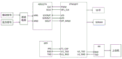
技术方案:本发明提供了一种输卤管道泄漏检测的智能终端,包括STM32F7芯片、压电式复合传感器、滤波电路模块、高精度A/D转换电路、GPS模块、外部SDRAM模块、 SD卡模块、4G通讯模块;Technical solution: The present invention provides an intelligent terminal for leakage detection of halogen transmission pipeline, including STM32F7 chip, piezoelectric composite sensor, filter circuit module, high-precision A/D conversion circuit, GPS module, external SDRAM module, SD card module , 4G communication module;
所述压电式复合传感器,用来检测输卤管道内部的压力信号和振动信号,其采集的模拟信号经过滤波电路模块、高精度A/D转换电路转化成数字信号,并通过SPI方式传输给 STM32F7芯片,将采集的数据写入外部SDRAM模块中,所述STM32F7芯片对数据进行分析,将疑似泄漏的信号,存储到SD卡中,通过4G模块传输到上位机。The piezoelectric composite sensor is used to detect the pressure signal and vibration signal inside the halogen transmission pipeline, and the collected analog signal is converted into a digital signal through a filter circuit module and a high-precision A/D conversion circuit, and is transmitted to the digital signal through SPI. The STM32F7 chip writes the collected data into the external SDRAM module. The STM32F7 chip analyzes the data, stores the suspected leaked signal in the SD card, and transmits it to the host computer through the 4G module.
进一步地,所述智能终端通过GPS模块的秒脉冲信号,同步采集输卤管道上下游某一时刻的振动信号和压力信号,并且利用GPS模块给采集到的数据加上时间戳。Further, the intelligent terminal synchronously collects the vibration signal and pressure signal at a certain moment upstream and downstream of the halogen transmission pipeline through the second pulse signal of the GPS module, and uses the GPS module to add time stamps to the collected data.
进一步地,高精度的A/D转换电路采用的是ADS1274。Further, the high-precision A/D conversion circuit adopts ADS1274.
本发明还公开了一种输卤管道泄漏检测的方法,包含如下步骤:The invention also discloses a method for leak detection of a halogen transmission pipeline, comprising the following steps:
Sept1:获取输卤管道内壁的压力和振动信号的历史数据集H;Sept1: Obtain the historical data set H of the pressure and vibration signals of the inner wall of the halogen pipeline;
Sept2:对历史数据集H进行离散S变换,记录S变换后的数据集D,将S变换后的数据集D分为训练集Z和测试集T;Sept2: Perform discrete S-transform on the historical data set H, record the S-transformed data set D, and divide the S-transformed data set D into a training set Z and a test set T;
Sept3:搭建LSTM模型,选取Sept2中训练集Z对LSTM模型进行训练类,并调整参数直至网络效果达到预想效果,确立LSTM模型;Sept3: Build the LSTM model, select the training set Z in Sept2 to train the LSTM model, and adjust the parameters until the network effect reaches the expected effect, and establish the LSTM model;
Sept4:将Sept2中测试集T作为LSTM模型的输入,对模型准确性进行验证;Sept4: Use the test set T in Sept2 as the input of the LSTM model to verify the accuracy of the model;
Sept5:对输卤管道当前的振动和压力信号进行同步采样,将当前采样数据进行S离散变换;Sept5: Simultaneously sample the current vibration and pressure signals of the halogen pipeline, and perform S discrete transformation on the current sampled data;
Sept6:将S变换后的当前数据输入到已经训练好的LSTM模型中,进行是否发生泄漏的预测。Sept6: Input the current data after S transformation into the trained LSTM model to predict whether leakage occurs.
优选地,所述S变换的离散形式如下所示:Preferably, the discrete form of the S-transform is as follows:


其中,N为信号的采样总点数,T为采用周期,X[kT](k=0,1,2…N-1)为采样后的信号,n为第n个点的序号,m为向左平移的频率点,j为虚数单位。Among them, N is the total number of sampling points of the signal, T is the adoption period, X[kT](k=0,1,2...N-1) is the sampled signal, n is the sequence number of the nth point, m is the direction Frequency point for left translation, j is an imaginary unit.
优选地,所述S变换的具体步骤如下:Preferably, the specific steps of the S transformation are as follows:
Step1.1:采集输卤管道内壁的压力信号X[kT];Step1.1: Collect the pressure signal X[kT] of the inner wall of the brine pipeline;
Step1.2:对压力信号X[kT]进行快速傅里叶变换,得到
Step1.3:n=0时,转到Step1.4,执行Step1.4与Step1.5;n不为0时,对于给定的频率点n,计算高斯窗函数的FFT:Step1.3: When n=0, go to Step1.4, and execute Step1.4 and Step1.5; when n is not 0, for a given frequency point n, calculate the FFT of the Gaussian window function:

Step1.4:根据n=0的公式计算给定时间点k对应的时间序列的S变换S[kt,0] (k=0,1,2,…,N-1表示时间采样点);Step1.4: Calculate the S transform S[kt,0] of the time series corresponding to the given time point k according to the formula of n=0 (k=0,1,2,...,N-1 represents the time sampling point);
Step1.5:令k=k+1,重复Step1.4,直至完成所有点的S变换,并结束S变换;Step1.5: Set k=k+1, repeat Step1.4 until the S-transformation of all points is completed, and end the S-transformation;
Step1.6:将Step1.2中的

Step1.7:对进行傅里叶变换后的高斯窗函数和平移后的频谱函数进行卷积,得到

Step 1.8:令n=n+1,重复Step1.6、Step1.7,直到计算完所有的频率点的S变换。Step 1.8: Let n=n+1, and repeat Step1.6 and Step1.7 until the S-transformation of all frequency points is calculated.
优选地,所述LSTM模型公式包括:Preferably, the LSTM model formula includes:
1)遗忘门:有条件地选择哪些信息从当前单元中抛弃,公式如下:1) Forget gate: Conditionally select which information is discarded from the current unit, the formula is as follows:
ft=σ(Wf.[ht-1,Xt]+bf)f t =σ(W f .[h t-1 ,X t ]+b f )
其中ft∈[0,1],1表示“完全保留”,0表示“完全舍弃”,其中ht-1表示的是上一个时刻LSTM的输出,Xt表示的是细胞的当前输入,Wf为遗忘门的权重矩阵,bf为偏置,σ是激活函数,通常选用Sigmoid函数,即
2)输入门:有条件地决定在单元中存储哪些信息,公式如下:2) Input gate: Conditionally decide what information to store in the cell, the formula is as follows:
it=σ(Wi.[ht-1,Xt]+bi)i t =σ(W i .[h t-1 ,X t ]+ bi )


其中,输入门it是由Xt和ht-1经过Sigmoid函数计算生成的,it同ft一样是一个介于[0,1]的向量;另一个是由Xt和ht-1经过tanh激活函数生成的一个向量


3)输出门:有条件地决定哪些信息需要输出,并输出信息;公式如下:3) Output gate: conditionally determine which information needs to be output, and output the information; the formula is as follows:
Ot=σ(Wo.[ht-1,Xt]+bo)O t =σ(W o .[h t-1 ,X t ]+b o )
ht=Ot*tanh(Ct)h t =O t *tanh(C t )
其中,运行一个Sigmoid层来确定细胞状态的哪个部分将输出出去,接着,把细胞状态通过tanh进行处理,得到一个在-1到1之间的值,并将它和Sigmoid门的输出相乘,最终仅会输出我们确定输出的那部分。Among them, a sigmoid layer is run to determine which part of the cell state will be output, then the cell state is processed through tanh to get a value between -1 and 1, and it is multiplied by the output of the sigmoid gate, In the end, only the part that we are sure to output will be output.
优选地,所述Sept3中通过交叉熵损失函数,来刻画实际输出和期望输出的差距,并使用随机梯度下降法最小化交叉熵损失函数,对LSTM模型进行参数调整,直至模型达到要求,其交叉熵损失函数公式为:Preferably, in the Sept3, a cross-entropy loss function is used to describe the difference between the actual output and the expected output, and the stochastic gradient descent method is used to minimize the cross-entropy loss function, and the parameters of the LSTM model are adjusted until the model meets the requirements, and its cross The entropy loss function formula is:

其中,

有益效果:Beneficial effects:
1.本发明通过S变换能充分的了解到输卤管道某一时刻数据时-频-模三维的特征,作为LSTM模型的输入,使得模型能够更好的学习数据的特点,从而增加模型判断的准确性。1. The present invention can fully understand the three-dimensional characteristics of the time-frequency-mode data of the brine pipeline at a certain moment through the S transformation, as the input of the LSTM model, so that the model can better learn the characteristics of the data, thereby increasing the model judgment. accuracy.
2.本发明通过LSTM对输卤管道内部的压力信号和振动信号进行建模,解决了数据之间的时间相关性。2. The present invention uses LSTM to model the pressure signal and vibration signal inside the halogen pipeline, and solves the time correlation between the data.
3.现有技术中,输卤管道的泄漏判断需要设置阈值,而采用本发明的检测方法可以避免人为设置阈值,增加泄露判断的准确性。3. In the prior art, a threshold value needs to be set for the leakage judgment of the brine pipeline, and the detection method of the present invention can avoid artificially setting the threshold value and increase the accuracy of leakage judgment.
附图说明Description of drawings
图1为本发明的泄漏检测装置的方框结构示意图;1 is a schematic block diagram of a leak detection device of the present invention;
图2本发明智能终端的电路连接图;Fig. 2 is the circuit connection diagram of the intelligent terminal of the present invention;
图3为本发明的整体框图;Fig. 3 is the overall block diagram of the present invention;
图4为本发明的S变换流程图;Fig. 4 is the S transform flow chart of the present invention;
图5为本发明的LSTM模型流程图;Fig. 5 is the LSTM model flow chart of the present invention;
图6为本发明的仿真数据图;Fig. 6 is the simulation data diagram of the present invention;
图7为本发明的S变换后数据图。FIG. 7 is a data diagram after S-transformation of the present invention.
具体实施方式Detailed ways
下面结合附图对本发明进行详细的介绍。The present invention will be described in detail below with reference to the accompanying drawings.
如图1所示一种输卤管道泄漏检测的智能终端,包括STM32F7芯片、压电式复合传感器、滤波电路模块、高精度A/D转换电路、GPS模块、外部SDRAM模块、SD卡模块、4G通讯模块。该智能终端通过GPS模块的秒脉冲信号,同步采集输卤管道上下游某一时刻的振动信号和压力信号,并且利用GPS模块给采集到的数据加上时间戳,便于之后的数据处理。采集到的模拟数据通过滤波电路模块去除杂波干扰,将滤波后的模拟信号通过A/D转换电路进行模数转换。As shown in Figure 1, an intelligent terminal for leakage detection of halogen transmission pipeline includes STM32F7 chip, piezoelectric composite sensor, filter circuit module, high-precision A/D conversion circuit, GPS module, external SDRAM module, SD card module, 4G communication module. The intelligent terminal synchronously collects the vibration signal and pressure signal at a certain moment upstream and downstream of the halogen transmission pipeline through the second pulse signal of the GPS module, and uses the GPS module to add time stamps to the collected data, which is convenient for subsequent data processing. The collected analog data is removed by the filter circuit module to remove clutter interference, and the filtered analog signal is converted to analog-to-digital by the A/D conversion circuit.
高精度的A/D转换电路采用的是ADS1274。ADS1274是24位逐次逼近型的模拟数字转换器,其中包含四路AD转换电路。ADS1274与STM32F7通过SPI进行数据传输。STM32F7 芯片先通过定时器的捕获功能接受GPS的PPS中断信号,当定时器捕获到上升沿时,此时在PPS中断处理函数中检测ADS1274的数据准备好信号
图2为电路的滤波电路图。本发明需要分析的是输卤管道内部振动所产生的交流信号,所以第一部分的滤波放大电路是将交流信号放大,直流信号作为载波信号,保持不变。第二部分为差分放大电路。对于直流信号来说,差分放大电路是共模输入,输出端的电压为0,避免了直流电压的干扰,同时也放大了所需要的交流信号。Figure 2 is a filter circuit diagram of the circuit. What the present invention needs to analyze is the AC signal generated by the internal vibration of the halogen transmission pipeline, so the filtering and amplifying circuit of the first part amplifies the AC signal, and the DC signal is used as the carrier signal and remains unchanged. The second part is the differential amplifier circuit. For the DC signal, the differential amplifier circuit is a common-mode input, and the voltage at the output terminal is 0, which avoids the interference of the DC voltage and also amplifies the required AC signal.
本发明还公开了一种输卤管道泄漏检测的方法,其整体流程图如图3所示,设信号的采样总点数为N,采用周期为T。检测方法主要包括如下步骤:The invention also discloses a method for leak detection of a halogen transmission pipeline, the overall flow chart of which is shown in Figure 3 , the total number of sampling points of the signal is set as N, and the adoption period is set as T. The detection method mainly includes the following steps:
Sept1:获取输卤管道内壁的压力和振动信号的历史数据集H。Sept1: Obtain the historical data set H of the pressure and vibration signals of the inner wall of the halogen pipeline.
通过压电式复合传感器获取管道内壁的压力信号(振动信号做相同分析),设采样后的信号为X[kT](k=0,1,2…N-1)。The pressure signal of the inner wall of the pipeline is obtained by the piezoelectric composite sensor (the vibration signal is analyzed in the same way), and the sampled signal is set as X[kT] (k=0,1,2...N-1).
Sept2:对历史数据集H进行离散S变换,记录S变换后的数据集D,将S变换后的数据集D分为训练集Z(总数据的70%)和测试集T(总数据的30%)Sept2: Perform discrete S transformation on the historical data set H, record the S transformed data set D, and divide the S transformed data set D into training set Z (70% of the total data) and test set T (30% of the total data) %)
S变换的离散形式如下所示:The discrete form of the S-transform is as follows:


其中,N为信号的采样总点数,T为采用周期,X[kT](k=0,1,2…N-1)为采样后的信号,n为第n个点的序号,m为向左平移的频率点,j为虚数单位。Among them, N is the total number of sampling points of the signal, T is the adoption period, X[kT](k=0,1,2...N-1) is the sampled signal, n is the sequence number of the nth point, m is the direction Frequency point for left translation, j is an imaginary unit.
对所有采集到信号(历史数据集H)进行离散S变换,记录S变换后的数据集。Discrete S-transformation is performed on all collected signals (historical data set H), and the S-transformed data set is recorded.
S变换的具体步骤如图4所示:The specific steps of S transformation are shown in Figure 4:
Step2.1:采集数据管道内壁的压力信号X[kT]。Step2.1: Collect the pressure signal X[kT] on the inner wall of the data pipeline.
Step2.2:对输入信号的X[kT]进行快速傅里叶变换,得到
Step2.3:n=0时,转到Step2.4,并执行Step2.4与Step2.5;当n不为0时,对于给定的频率点n,计算高斯窗函数的FFT:Step2.3: When n=0, go to Step2.4, and execute Step2.4 and Step2.5; when n is not 0, for a given frequency point n, calculate the FFT of the Gaussian window function:

Step2.4:根据n=0的公式计算给定时间点k对应的时间序列的S变换S[Kt,0] (k=0,1,2,…,N-1表示时间采样点)。Step2.4: Calculate the S-transform S[Kt,0] of the time series corresponding to the given time point k according to the formula of n=0 (k=0,1,2,...,N-1 represents the time sampling point).
Step2.5:令k=k+1,重复Step2.4,直至完成所有点的S变换。Step2.5: Set k=k+1, and repeat Step2.4 until the S transformation of all points is completed.
Step2.6:将Step2.2中的

Step2.7:对进行傅里叶变换后的高斯窗函数和平移后的频谱函数进行卷积,得到

Step2.8:令n=n+1,重复Step2.6,Step2.7,直到计算完所有的频率点的S变换。Step2.8: Let n=n+1, and repeat Step2.6 and Step2.7 until the S-transformation of all frequency points is calculated.
Sept3:N个信号点的S变换后得到复数矩阵,利用该矩阵搭建LSTM模型,选取Sept2中训练集Z对LSTM模型进行训练类,并调整参数直至网络效果达到预想效果,确立LSTM 模型。Sept3: After S-transformation of N signal points, a complex matrix is obtained, and the LSTM model is built using the matrix. The training set Z in Sept2 is selected to train the LSTM model, and the parameters are adjusted until the network effect reaches the expected effect, and the LSTM model is established.
Sept4:将Sept2中测试集T作为LSTM模型的输入,对模型准确性进行验证。Sept4: Use the test set T in Sept2 as the input of the LSTM model to verify the accuracy of the model.
Sept5:对输卤管道当前的振动和压力信号进行同步采样,将当前采样数据进行S离散变换。Sept5: Simultaneously sample the current vibration and pressure signals of the halogen pipeline, and perform S discrete transformation on the current sampled data.
Sept6:将S变换后的当前数据输入到已经训练好的LSTM模型中,进行是否发生泄漏的预测。Sept6: Input the current data after S transformation into the trained LSTM model to predict whether leakage occurs.
上述的LSTM模型,其公式包括:The above LSTM model, its formula includes:
1)遗忘门:有条件地选择哪些信息从当前单元中抛弃,公式如下:1) Forget gate: Conditionally select which information is discarded from the current unit, the formula is as follows:
ft=σ(Wf.[ht-1,Xt]+bf)f t =σ(W f .[h t-1 ,X t ]+b f )
其中ft∈[0,1],1表示“完全保留”,0表示“完全舍弃”,其中ht-1表示的是上一个时刻LSTM的输出,Xt表示的是细胞的当前输入,Wf为遗忘门的权重矩阵,bf为偏置,σ是激活函数,通常选用Sigmoid函数,即
2)输入门:有条件地决定在单元中存储哪些信息,公式如下:2) Input gate: Conditionally decide what information to store in the cell, the formula is as follows:
it=σ(Wi.[ht-1,Xt]+bi)i t =σ(W i .[h t-1 ,X t ]+ bi )


其中,输入门it是由Xt和ht-1经过Sigmoid函数计算生成的,it同ft一样是一个介于[0,1]的向量;另一个是由Xt和ht-1经过tanh激活函数生成的一个向量


3)输出门:有条件地决定哪些信息需要输出,并输出信息;公式如下:3) Output gate: conditionally determine which information needs to be output, and output the information; the formula is as follows:
Ot=σ(Wo.[ht-1,Xt]+bo)O t =σ(W o .[h t-1 ,X t ]+b o )
ht=Ot*tanh(Ct)h t =O t *tanh(C t )
其中,运行一个Sigmoid层来确定细胞状态的哪个部分将输出出去,接着,把细胞状态通过tanh进行处理,得到一个在-1到1之间的值,并将它和Sigmoid门的输出相乘,最终仅会输出我们确定输出的那部分。Among them, a sigmoid layer is run to determine which part of the cell state will be output, then the cell state is processed through tanh to get a value between -1 and 1, and it is multiplied by the output of the sigmoid gate, In the end, only the part that we are sure to output will be output.
设“1”标记为发生泄漏,“0”表示管道未发生泄漏。通过随机梯度下降法最小化交叉熵损失进行模型参数调整,直到模型的准确性达到要求。其损失函数公式为:A "1" is set to mark a leak, and a "0" means that the pipe is not leaking. The model parameters are adjusted by minimizing the cross-entropy loss by stochastic gradient descent until the accuracy of the model meets the requirements. Its loss function formula is:

其中,

图6是输卤管道仿真图,对采集信号附加白噪声信号从而模拟输卤管道的噪声。图7 是将仿真数据进行S变换后的二维等高线图,即输卤管道的时-频-模图形。最后将S变换后的矩阵作为LSTM模型的输入,输出为“1”时,则表发生泄漏,输出为“0”时,则表示未发生泄漏。Fig. 6 is the simulation diagram of the halogen transmission pipeline, adding a white noise signal to the collected signal to simulate the noise of the halogen transmission pipeline. Figure 7 is a two-dimensional contour map after S-transformation of the simulation data, that is, the time-frequency-mode graph of the brine pipeline. Finally, the S-transformed matrix is used as the input of the LSTM model. When the output is "1", the table leaks, and when the output is "0", it means that no leakage occurs.
上述实施方式只为说明本发明的技术构思及特点,其目的在于让熟悉此项技术的人能够了解本发明的内容并据以实施,并不能以此限制本发明的保护范围。凡根据本发明精神实质所做的等效变换或修饰,都应涵盖在本发明的保护范围之内。The above-mentioned embodiments are only intended to illustrate the technical concept and features of the present invention, and the purpose is to enable those who are familiar with the art to understand the content of the present invention and implement it accordingly, and cannot limit the protection scope of the present invention. All equivalent transformations or modifications made according to the spirit of the present invention should be covered within the protection scope of the present invention.
Claims (8)


Priority Applications (1)
| Application Number | Priority Date | Filing Date | Title |
|---|---|---|---|
| CN202010202066.4A CN111365624A (en) | 2020-03-20 | 2020-03-20 | A kind of intelligent terminal and method for leakage detection of brine pipeline |
Applications Claiming Priority (1)
| Application Number | Priority Date | Filing Date | Title |
|---|---|---|---|
| CN202010202066.4A CN111365624A (en) | 2020-03-20 | 2020-03-20 | A kind of intelligent terminal and method for leakage detection of brine pipeline |
Publications (1)
| Publication Number | Publication Date |
|---|---|
| CN111365624A true CN111365624A (en) | 2020-07-03 |
Family
ID=71207656
Family Applications (1)
| Application Number | Title | Priority Date | Filing Date |
|---|---|---|---|
| CN202010202066.4A Pending CN111365624A (en) | 2020-03-20 | 2020-03-20 | A kind of intelligent terminal and method for leakage detection of brine pipeline |
Country Status (1)
| Country | Link |
|---|---|
| CN (1) | CN111365624A (en) |
Cited By (4)
| Publication number | Priority date | Publication date | Assignee | Title |
|---|---|---|---|---|
| CN111693264A (en) * | 2020-06-16 | 2020-09-22 | 清华大学 | Fluid machinery diagnosis system and method based on artificial intelligence and big data |
| CN113446593A (en) * | 2021-06-25 | 2021-09-28 | 吉林化工学院 | Boiler pressure-bearing pipeline leakage detection system |
| CN114462688A (en) * | 2022-01-11 | 2022-05-10 | 湖南大学 | Tube explosion detection method based on LSTM model and dynamic threshold determination algorithm |
| CN116306377A (en) * | 2023-04-04 | 2023-06-23 | 中国石油大学(华东) | Method and system for rapidly predicting consequences of hydrogen refueling station leakage accidents |
Citations (6)
| Publication number | Priority date | Publication date | Assignee | Title |
|---|---|---|---|---|
| US20060059977A1 (en) * | 2004-09-23 | 2006-03-23 | Lawrence Kates | System and method for utility metering and leak detection |
| CN101546906A (en) * | 2009-05-05 | 2009-09-30 | 昆明理工大学 | Method for fault line selection of electric distribution network by using S transformation energy relative entropy |
| CN102563362A (en) * | 2011-12-31 | 2012-07-11 | 杭州哲达科技股份有限公司 | Compressed air system and intelligent pipe network leakage detecting method for same |
| CN104075122A (en) * | 2014-06-12 | 2014-10-01 | 东北大学 | Portable integrated pipe leakage detection device and method |
| CN106287240A (en) * | 2016-09-05 | 2017-01-04 | 中国石油大学(华东) | A kind of pipeline leakage testing device based on acoustic emission and single-sensor localization method |
| CN110222953A (en) * | 2018-12-29 | 2019-09-10 | 北京理工大学 | A kind of power quality hybrid perturbation analysis method based on deep learning |
-
2020
- 2020-03-20 CN CN202010202066.4A patent/CN111365624A/en active Pending
Patent Citations (6)
| Publication number | Priority date | Publication date | Assignee | Title |
|---|---|---|---|---|
| US20060059977A1 (en) * | 2004-09-23 | 2006-03-23 | Lawrence Kates | System and method for utility metering and leak detection |
| CN101546906A (en) * | 2009-05-05 | 2009-09-30 | 昆明理工大学 | Method for fault line selection of electric distribution network by using S transformation energy relative entropy |
| CN102563362A (en) * | 2011-12-31 | 2012-07-11 | 杭州哲达科技股份有限公司 | Compressed air system and intelligent pipe network leakage detecting method for same |
| CN104075122A (en) * | 2014-06-12 | 2014-10-01 | 东北大学 | Portable integrated pipe leakage detection device and method |
| CN106287240A (en) * | 2016-09-05 | 2017-01-04 | 中国石油大学(华东) | A kind of pipeline leakage testing device based on acoustic emission and single-sensor localization method |
| CN110222953A (en) * | 2018-12-29 | 2019-09-10 | 北京理工大学 | A kind of power quality hybrid perturbation analysis method based on deep learning |
Non-Patent Citations (3)
| Title |
|---|
| 范乐: "热网关键节点泄漏监测系统的设计与研发", 《中国优秀硕士学位论文全文数据库 工程科技Ⅱ辑》 * |
| 邵萌等: "《微位移平台数据采集与处理技术》", 30 September 2018, 东北大学出版社 * |
| 雷振山等: "《LabVIEW高级编程与虚拟仪器工程应用》", 31 August 2013, 中国铁道出版社 * |
Cited By (6)
| Publication number | Priority date | Publication date | Assignee | Title |
|---|---|---|---|---|
| CN111693264A (en) * | 2020-06-16 | 2020-09-22 | 清华大学 | Fluid machinery diagnosis system and method based on artificial intelligence and big data |
| CN111693264B (en) * | 2020-06-16 | 2021-03-16 | 清华大学 | Fluid machinery diagnosis system and method based on artificial intelligence and big data |
| CN113446593A (en) * | 2021-06-25 | 2021-09-28 | 吉林化工学院 | Boiler pressure-bearing pipeline leakage detection system |
| CN114462688A (en) * | 2022-01-11 | 2022-05-10 | 湖南大学 | Tube explosion detection method based on LSTM model and dynamic threshold determination algorithm |
| CN116306377A (en) * | 2023-04-04 | 2023-06-23 | 中国石油大学(华东) | Method and system for rapidly predicting consequences of hydrogen refueling station leakage accidents |
| CN116306377B (en) * | 2023-04-04 | 2024-04-05 | 中国石油大学(华东) | A method and system for quickly predicting the consequences of a hydrogen refueling station leakage accident |
Similar Documents
| Publication | Publication Date | Title |
|---|---|---|
| CN111365624A (en) | A kind of intelligent terminal and method for leakage detection of brine pipeline | |
| CN113707176B (en) | A Transformer Fault Detection Method Based on Acoustic Signal and Deep Learning Technology | |
| CN108268935B (en) | PM2.5 concentration value prediction method and system based on time sequence recurrent neural network | |
| CN110454687A (en) | A pipeline multi-point leak location method based on improved VMD | |
| CN110096810B (en) | Industrial process soft measurement method based on layer-by-layer data expansion deep learning | |
| CN108805269A (en) | A method of TRANSFORMATION RATIO is picked up based on LSTM Recognition with Recurrent Neural Network | |
| CN101900789B (en) | Fault Diagnosis Method of Tolerance Analog Circuit Based on Wavelet Transform and Fractal Dimension | |
| CN115824519B (en) | Comprehensive diagnosis method of valve leakage fault based on multi-sensor information fusion | |
| CN110728195B (en) | Power quality disturbance detection method based on YOLO algorithm | |
| CN111695465B (en) | Pipe network fault diagnosis and positioning method and system based on pressure wave mode identification | |
| CN113111923A (en) | Water supply network leakage detection and positioning method based on one-dimensional migration learning convolutional neural network integrated model | |
| CN111898644A (en) | An intelligent identification method for aerospace liquid engine health status under fault-free samples | |
| CN103852525B (en) | Acoustic emission signal recognition methods based on AR-HMM | |
| CN117332324A (en) | Pipeline leakage detection method and device, electronic equipment and storage medium | |
| CN113920255B (en) | High-efficient mapping system based on point cloud data | |
| CN114295967A (en) | A fault diagnosis method for analog circuits based on transfer neural network | |
| CN118706436A (en) | A gearbox fault diagnosis method based on multi-scale dynamic convolutional neural network | |
| CN118623236A (en) | Pipeline leakage detection method, device, equipment and computer storage medium | |
| CN114943189B (en) | XGboost-based acoustic velocity profile inversion method and system | |
| CN114494273A (en) | Bridge damping ratio identification method based on monitoring data and deep learning | |
| Zhang | Flow measurement of natural gas in pipeline based on 1d-convolutional neural network | |
| CN102306249B (en) | Equipment efficiency simulation method and system | |
| CN108646719B (en) | A weak fault detection method and system | |
| CN113408357A (en) | Method for generating flutter turbulence response signal to impulse response signal | |
| CN114063164A (en) | Method and device for picking up first arrivals based on U-net++ convolutional neural network |
Legal Events
| Date | Code | Title | Description |
|---|---|---|---|
| PB01 | Publication | ||
| PB01 | Publication | ||
| SE01 | Entry into force of request for substantive examination | ||
| SE01 | Entry into force of request for substantive examination | ||
| RJ01 | Rejection of invention patent application after publication | ||
| RJ01 | Rejection of invention patent application after publication |
Application publication date: 20200703 |