CN111358058A - Battery case, electronic cigarette and assembling method - Google Patents
Battery case, electronic cigarette and assembling method Download PDFInfo
- Publication number
- CN111358058A CN111358058A CN201811599014.4A CN201811599014A CN111358058A CN 111358058 A CN111358058 A CN 111358058A CN 201811599014 A CN201811599014 A CN 201811599014A CN 111358058 A CN111358058 A CN 111358058A
- Authority
- CN
- China
- Prior art keywords
- casing
- sleeve
- battery case
- limiting
- groove
- Prior art date
- Legal status (The legal status is an assumption and is not a legal conclusion. Google has not performed a legal analysis and makes no representation as to the accuracy of the status listed.)
- Pending
Links
Images


Classifications
-
- A—HUMAN NECESSITIES
- A24—TOBACCO; CIGARS; CIGARETTES; SIMULATED SMOKING DEVICES; SMOKERS' REQUISITES
- A24F—SMOKERS' REQUISITES; MATCH BOXES; SIMULATED SMOKING DEVICES
- A24F40/00—Electrically operated smoking devices; Component parts thereof; Manufacture thereof; Maintenance or testing thereof; Charging means specially adapted therefor
- A24F40/90—Arrangements or methods specially adapted for charging batteries thereof
- A24F40/95—Arrangements or methods specially adapted for charging batteries thereof structurally associated with cases
-
- A—HUMAN NECESSITIES
- A24—TOBACCO; CIGARS; CIGARETTES; SIMULATED SMOKING DEVICES; SMOKERS' REQUISITES
- A24F—SMOKERS' REQUISITES; MATCH BOXES; SIMULATED SMOKING DEVICES
- A24F40/00—Electrically operated smoking devices; Component parts thereof; Manufacture thereof; Maintenance or testing thereof; Charging means specially adapted therefor
- A24F40/40—Constructional details, e.g. connection of cartridges and battery parts
- A24F40/42—Cartridges or containers for inhalable precursors
-
- A—HUMAN NECESSITIES
- A24—TOBACCO; CIGARS; CIGARETTES; SIMULATED SMOKING DEVICES; SMOKERS' REQUISITES
- A24F—SMOKERS' REQUISITES; MATCH BOXES; SIMULATED SMOKING DEVICES
- A24F40/00—Electrically operated smoking devices; Component parts thereof; Manufacture thereof; Maintenance or testing thereof; Charging means specially adapted therefor
- A24F40/40—Constructional details, e.g. connection of cartridges and battery parts
-
- H—ELECTRICITY
- H01—ELECTRIC ELEMENTS
- H01M—PROCESSES OR MEANS, e.g. BATTERIES, FOR THE DIRECT CONVERSION OF CHEMICAL ENERGY INTO ELECTRICAL ENERGY
- H01M50/00—Constructional details or processes of manufacture of the non-active parts of electrochemical cells other than fuel cells, e.g. hybrid cells
- H01M50/10—Primary casings; Jackets or wrappings
- H01M50/102—Primary casings; Jackets or wrappings characterised by their shape or physical structure
- H01M50/107—Primary casings; Jackets or wrappings characterised by their shape or physical structure having curved cross-section, e.g. round or elliptic
-
- H—ELECTRICITY
- H01—ELECTRIC ELEMENTS
- H01M—PROCESSES OR MEANS, e.g. BATTERIES, FOR THE DIRECT CONVERSION OF CHEMICAL ENERGY INTO ELECTRICAL ENERGY
- H01M50/00—Constructional details or processes of manufacture of the non-active parts of electrochemical cells other than fuel cells, e.g. hybrid cells
- H01M50/20—Mountings; Secondary casings or frames; Racks, modules or packs; Suspension devices; Shock absorbers; Transport or carrying devices; Holders
- H01M50/247—Mountings; Secondary casings or frames; Racks, modules or packs; Suspension devices; Shock absorbers; Transport or carrying devices; Holders specially adapted for portable devices, e.g. mobile phones, computers, hand tools or pacemakers
-
- H—ELECTRICITY
- H01—ELECTRIC ELEMENTS
- H01M—PROCESSES OR MEANS, e.g. BATTERIES, FOR THE DIRECT CONVERSION OF CHEMICAL ENERGY INTO ELECTRICAL ENERGY
- H01M50/00—Constructional details or processes of manufacture of the non-active parts of electrochemical cells other than fuel cells, e.g. hybrid cells
- H01M50/20—Mountings; Secondary casings or frames; Racks, modules or packs; Suspension devices; Shock absorbers; Transport or carrying devices; Holders
- H01M50/262—Mountings; Secondary casings or frames; Racks, modules or packs; Suspension devices; Shock absorbers; Transport or carrying devices; Holders with fastening means, e.g. locks
- H01M50/264—Mountings; Secondary casings or frames; Racks, modules or packs; Suspension devices; Shock absorbers; Transport or carrying devices; Holders with fastening means, e.g. locks for cells or batteries, e.g. straps, tie rods or peripheral frames
-
- A—HUMAN NECESSITIES
- A24—TOBACCO; CIGARS; CIGARETTES; SIMULATED SMOKING DEVICES; SMOKERS' REQUISITES
- A24F—SMOKERS' REQUISITES; MATCH BOXES; SIMULATED SMOKING DEVICES
- A24F40/00—Electrically operated smoking devices; Component parts thereof; Manufacture thereof; Maintenance or testing thereof; Charging means specially adapted therefor
- A24F40/10—Devices using liquid inhalable precursors
-
- Y—GENERAL TAGGING OF NEW TECHNOLOGICAL DEVELOPMENTS; GENERAL TAGGING OF CROSS-SECTIONAL TECHNOLOGIES SPANNING OVER SEVERAL SECTIONS OF THE IPC; TECHNICAL SUBJECTS COVERED BY FORMER USPC CROSS-REFERENCE ART COLLECTIONS [XRACs] AND DIGESTS
- Y02—TECHNOLOGIES OR APPLICATIONS FOR MITIGATION OR ADAPTATION AGAINST CLIMATE CHANGE
- Y02E—REDUCTION OF GREENHOUSE GAS [GHG] EMISSIONS, RELATED TO ENERGY GENERATION, TRANSMISSION OR DISTRIBUTION
- Y02E60/00—Enabling technologies; Technologies with a potential or indirect contribution to GHG emissions mitigation
- Y02E60/10—Energy storage using batteries
Landscapes
- Chemical & Material Sciences (AREA)
- Chemical Kinetics & Catalysis (AREA)
- Electrochemistry (AREA)
- General Chemical & Material Sciences (AREA)
- Life Sciences & Earth Sciences (AREA)
- Engineering & Computer Science (AREA)
- Biophysics (AREA)
- Computer Hardware Design (AREA)
- Battery Mounting, Suspending (AREA)
Abstract
本发明公开一种电池壳,其包括第一套壳和第二套壳,第一套壳的侧壁上沿第一套壳的轴向开设有限位凹槽,限位凹槽贯通第一套壳的内、外侧壁及第一套壳的一端面,第一套壳的外壁上沿第一套壳的轴向凸设有导滑筋,第二套壳的内壁上沿第二套壳的轴向凸设有与限位凹槽配合的限位凸起,第二套壳的侧壁上沿第二套壳的轴向开设有与导滑筋配合的导滑槽,导滑槽贯通第二套壳的内、外侧壁及第二套壳的一端面,当第二套壳套设于第一套壳的外部时,限位凸起与限位凹槽相卡合,且导滑筋与导滑槽相卡合。本发明的电池壳,使得第一套壳和第二套壳具有弹性变形能力,防止发生变形。本发明还公开了一种带有该电池壳的电子烟以及电池壳的装配方法。

The invention discloses a battery casing, which comprises a first casing and a second casing. A limiting groove is formed on the side wall of the first casing along the axial direction of the first casing, and the limiting groove penetrates through the first casing. The inner and outer side walls of the casing and one end face of the first casing, the outer wall of the first casing is protruded with guide sliding ribs along the axial direction of the first casing, and the inner wall of the second casing is along the axis of the second casing. The axial projection is provided with a limit protrusion that cooperates with the limit groove, the side wall of the second casing is provided with a guide groove matched with the guide rib along the axial direction of the second casing, and the guide groove penetrates through the second casing. The inner and outer side walls of the second casing and one end face of the second casing, when the second casing is sleeved on the outside of the first casing, the limiting protrusions are engaged with the limiting grooves, and the guide ribs Engage with the guide chute. The battery case of the present invention enables the first sleeve and the second sleeve to have elastic deformation ability to prevent deformation. The invention also discloses an electronic cigarette with the battery case and an assembling method of the battery case.
Description
技术领域technical field
本发明涉及模拟吸烟技术领域,特别地,涉及一种电池壳及电子烟、装配方法。The invention relates to the technical field of simulated smoking, in particular, to a battery case, an electronic cigarette, and an assembling method.
背景技术Background technique
便携式电子烟,俗称“小烟”,其包括烟弹以及与烟弹电性连接的电源装置,其中,电源装置包括电池壳以及安装在电池壳内的电池,现在,用于安装电池的电池壳多为棱柱状或者圆筒状一体成型结构,此类电池壳生产完毕后,在运输时难免会发生变形的情况,导致无法使用,从而造成资源浪费,进而增加了生产成本。Portable electronic cigarettes, commonly known as "small cigarettes", include a pod and a power supply device electrically connected to the pod, wherein the power supply device includes a battery case and a battery installed in the battery case, and now, a battery case for installing the battery Most of them are prismatic or cylindrical integrally formed structures. After the production of such battery casings, it is inevitable that deformation will occur during transportation, resulting in unusable use, resulting in waste of resources and increased production costs.
发明内容SUMMARY OF THE INVENTION
基于此,有必要提供一种可防止变形的电池壳;Based on this, it is necessary to provide a battery case that can prevent deformation;
还有必要提供一种带有该电池壳的电子烟;It is also necessary to provide an electronic cigarette with the battery case;
更有必要提供一种用于该电池壳或电子烟的电池壳的装配方法。It is more necessary to provide an assembly method for the battery case or the battery case of the electronic cigarette.
本发明解决其技术问题所采用的技术方案是:一种电池壳,所述电池壳包括第一套壳和第二套壳,所述第一套壳的侧壁上沿所述第一套壳的轴向开设有限位凹槽,所述限位凹槽贯通所述第一套壳的内、外侧壁及所述第一套壳的一端面,所述第一套壳的外壁上沿所述第一套壳的轴向凸设有导滑筋,所述第二套壳的内壁上沿所述第二套壳的轴向凸设有与所述限位凹槽配合的限位凸起,所述第二套壳的侧壁上沿所述第二套壳的轴向开设有与所述导滑筋配合的导滑槽,所述导滑槽贯通所述第二套壳的内、外侧壁及第二套壳的一端面,当所述第二套壳套设于所述第一套壳的外部时,所述限位凸起与所述限位凹槽相卡合,且所述导滑筋与所述导滑槽相卡合。The technical solution adopted by the present invention to solve the technical problem is as follows: a battery case, the battery case includes a first sleeve and a second sleeve, and the side wall of the first sleeve is along the first sleeve. A limiting groove is provided in the axial direction of the The axial direction of the first casing is protruded with a guide rib, and the inner wall of the second casing is protruded with a limit protrusion that cooperates with the limit groove along the axial direction of the second casing. The side wall of the second casing is provided with a guide chute which is matched with the guide rib along the axial direction of the second casing, and the guide groove penetrates the inner and outer sides of the second casing the wall and one end face of the second casing, when the second casing is sleeved on the outside of the first casing, the limiting protrusion is engaged with the limiting groove, and the The guide ribs are engaged with the guide grooves.
进一步地,所述限位凸起有两个,且对称设置在所述第一套壳相对的侧壁上,所述导滑筋有两个,且对称设置在所述第一套壳相对的侧壁上,两个所述限位凹槽之间的对称面与两个所述导滑筋之间的对称面相垂直。Further, there are two said limiting protrusions, and they are symmetrically arranged on the opposite side walls of the first casing, and there are two said guide ribs, and they are symmetrically arranged on the opposite sides of the first casing. On the side wall, the symmetry plane between the two limiting grooves is perpendicular to the symmetry plane between the two sliding ribs.
进一步地,所述第二套壳的内部安装有隔板,所述隔板沿所述第二套壳的径向设置。Further, a baffle plate is installed inside the second casing, and the baffle plate is arranged along the radial direction of the second casing.
进一步地,所述第一套壳与所述第二套壳围设而形成一空腔,所述隔板将所述空腔隔设为收容腔以及收容槽,所述收容槽位于所述收容腔的的上方。Further, the first casing and the second casing are enclosed to form a cavity, the baffle partitions the cavity into a receiving cavity and a receiving groove, and the receiving groove is located in the receiving cavity the top of the .
进一步地,所述第一套壳呈上端具有开口的中空筒状结构,所述隔板远离所述第一套壳的封闭端设置,使得所述收容腔形成一密闭结构,所述第二套壳呈上下两端贯通的中空筒状结构,使得所述收容槽的上端形成一开口。Further, the first casing has a hollow cylindrical structure with an opening at the upper end, and the baffle is arranged away from the closed end of the first casing, so that the receiving cavity forms a closed structure, and the second casing is The shell is in the form of a hollow cylindrical structure with upper and lower ends passing through, so that an opening is formed at the upper end of the receiving groove.
进一步地,所述隔板的上端面凸设有安装柱,所述安装柱沿所述安装柱的轴向开设有感应通道,所述感应通道的上端贯通所述安装柱的上端面,所述感应通道的下端贯通所述隔板的下端面。Further, an installation column is protruded on the upper end surface of the partition plate, an induction channel is opened along the axial direction of the installation column, and the upper end of the induction channel penetrates through the upper end surface of the installation column. The lower end of the induction channel penetrates through the lower end surface of the partition.
进一步地,所述隔板上还开设有第一电极孔和第二电极孔,所述第一电极孔与所述第二电极孔关于所述感应通道对称设置。Further, a first electrode hole and a second electrode hole are also opened on the separator, and the first electrode hole and the second electrode hole are symmetrically arranged with respect to the induction channel.
一种电子烟,所述电子烟包括电源装置,所述电源装置包括前述任一项所述的电池壳,所述电源装置还包括电池组件,所述电池组件包括安装在所述电池壳内的电池。An electronic cigarette, the electronic cigarette includes a power supply device, the power supply device includes the battery case according to any one of the foregoing, the power supply device further includes a battery assembly, and the battery assembly includes a battery installed in the battery case. Battery.
进一步地,所述电子烟还包括烟弹,所述第一套壳与所述第二套壳围设形成一空腔,所述第二套壳内设置有隔板,所述隔板将所述空腔隔设为用于安装所述电池组件的收容腔以及用于安装所述烟弹的收容槽,所述收容槽位于所述收容腔的上方。Further, the electronic cigarette also includes a cartridge, the first casing and the second casing are enclosed to form a cavity, and a partition is arranged in the second casing, and the partition separates the The cavity is partitioned into an accommodating cavity for installing the battery assembly and a accommodating groove for installing the pod, and the accommodating groove is located above the accommodating cavity.
进一步地,所述隔板上安装有第一电极柱和第二电极柱,所述第一电极柱与所述电池的正、负极中的一个电极电性连接,所述第二电极柱与所述电池的正、负极中的另一个电极电性连接,所述烟弹上具有第一电极端子和第二电极端子,当所述烟弹与所述电源装置处于第一连接状态时,所述第一电极柱与所述第一电极端子接触并电性连接,当所述烟弹与所述电源装置处于第二连接状态时,所述第一电极柱与所述第二电极端子接触并电性连接。Further, a first electrode column and a second electrode column are installed on the separator, the first electrode column is electrically connected to one of the positive and negative electrodes of the battery, and the second electrode column is connected to the battery. The other one of the positive and negative electrodes of the battery is electrically connected, and the cartridge has a first electrode terminal and a second electrode terminal. When the cartridge and the power supply device are in a first connection state, the cartridge is in a first connection state. The first electrode column is in contact with the first electrode terminal and is electrically connected. When the cartridge and the power supply device are in a second connection state, the first electrode column is in contact with the second electrode terminal and is electrically connected. sexual connection.
一种电池壳的装配方法,适用于前述任一项所述的电池壳以及前述任一项所述的电子烟,所述装配方法包括以下步骤:An assembling method of a battery case, applicable to the battery case described in any of the foregoing and the electronic cigarette described in any of the foregoing, the assembling method comprising the following steps:
步骤一:分别夹持所述第一套壳和所述第二套壳,使所述限位凸起与所述限位凹槽的位置可对应配合,同时,所述导滑筋与所述导滑槽的位置对应配合;Step 1: Clamp the first casing and the second casing respectively, so that the position of the limit protrusion and the position of the limit groove can be matched correspondingly, and at the same time, the guide rib and the The position of the guide chute corresponds to the match;
步骤二:将所述第二套壳套设在所述第一套壳的外部,使得所述限位凸起与所述限位凹槽相卡合的同时,所述导滑筋与所述导滑槽相卡合。Step 2: Sleeve the second casing on the outside of the first casing, so that when the limiting protrusion is engaged with the limiting groove, the guide rib and the The guide chute is engaged.
进一步地,所述限位凸起沿所述第二套壳的纵长轴向延伸,所述限位凸起的一端设有隔板,所述隔板沿所述第二套壳的径向设置;所述第二套壳套设在所述第一套壳的外部后,所述隔板限制所述第一套壳相对所述第二套壳发生轴向位移,所述限位凸起限制所述第一套壳相对所述第二套壳发生径向位移。Further, the limiting protrusion extends along the longitudinal axis of the second casing, and one end of the limiting protrusion is provided with a baffle, and the baffle is along the radial direction of the second casing. After the second casing is sleeved on the outside of the first casing, the baffle restricts the axial displacement of the first casing relative to the second casing, and the limiting protrusion The radial displacement of the first casing relative to the second casing is restricted.
本发明的有益效果是:本发明提供的电池壳或电子烟,电池壳包括相互套设的第一套壳和第二套壳,第一套壳上的限位凹槽使得第一套壳具有一定的弹性变形能力,第二套壳上的导滑槽使得第二套壳具有一定的弹性变形能力,防止了运输过程中发生变形,减少了资源浪费,节省了生产成本。The beneficial effects of the present invention are: in the battery case or electronic cigarette provided by the present invention, the battery case includes a first case and a second case that are sleeved with each other, and the limiting groove on the first case enables the first case to have A certain elastic deformation ability, the guide chute on the second casing makes the second casing have a certain elastic deformation ability, which prevents deformation during transportation, reduces waste of resources, and saves production costs.
附图说明Description of drawings
下面结合附图和实施例对本发明作进一步说明。The present invention will be further described below with reference to the accompanying drawings and embodiments.
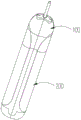
图1是本发明的电子烟的立体图;1 is a perspective view of an electronic cigarette of the present invention;
图2是图1所示电子烟的分解图;Fig. 2 is an exploded view of the electronic cigarette shown in Fig. 1;
图3是图2所示电子烟中烟弹的部分分解图;Fig. 3 is a partial exploded view of the cartridge in the electronic cigarette shown in Fig. 2;
图4是图2所示电子烟中烟弹的另一视角的部分分解图;FIG. 4 is a partially exploded view from another perspective of the cartridge in the electronic cigarette shown in FIG. 2;
图5是图4所示烟弹中底座的俯视图;Fig. 5 is the top view of the base in the cartridge shown in Fig. 4;
图6是图4所示烟弹中底座的仰视图;Fig. 6 is the bottom view of the base in the cartridge shown in Fig. 4;
图7是图2所示电子烟中烟弹的剖视图;Fig. 7 is the sectional view of the cartridge in the electronic cigarette shown in Fig. 2;
图8是图2所示电子烟中电源装置的部分分解图;Fig. 8 is a partial exploded view of the power supply device in the electronic cigarette shown in Fig. 2;
图9是图8所示电源装置中第一套壳的主视图;Fig. 9 is the front view of the first casing in the power supply device shown in Fig. 8;
图10是图9所示电源装置中第一套壳的仰视图;Fig. 10 is the bottom view of the first casing in the power supply device shown in Fig. 9;
图11是图8所示电源装置中第一套壳的剖视图;Figure 11 is a cross-sectional view of the first casing in the power supply device shown in Figure 8;
图12是图8所示电源装置中第二套壳的另一视角的结构示意图;FIG. 12 is a schematic structural diagram from another perspective of the second casing in the power supply device shown in FIG. 8;
图13是图12所示第二套壳的仰视图;Figure 13 is a bottom view of the second casing shown in Figure 12;
图14是图8所示第二套壳的剖视图;Figure 14 is a cross-sectional view of the second casing shown in Figure 8;
图15是图8所示电源装置中电池组件的结构示意图;15 is a schematic structural diagram of a battery assembly in the power supply device shown in FIG. 8;
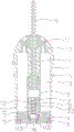
图16是图1所示电子烟的剖视图。FIG. 16 is a cross-sectional view of the electronic cigarette shown in FIG. 1 .
图中零部件名称及编号分别为:The names and numbers of the parts in the figure are:
烟弹100 烟弹本体11 储液腔110
通气管111 注液口112 密封塞17
卡槽113 卡嵌凸起115 密封件12Card slot 113 Snap-in
通孔121 凹槽122 雾化头13Through
雾化管131 雾化腔130 进液口1312
导液件132 加热件133 底座14
凸起141 卡扣142 连接筒143
第一安装槽144 第二安装槽145 第一穿孔1431The
第二穿孔1432 感应通道146 进气孔147Second through
过气空隙148 过气间隙149 第一挤压件15
第二挤压件16 套管18 提拉杆19
电源装置200 电池壳21 第一套壳211
限位凹槽2111 导滑筋2112 收容腔2110Limiting
USB插槽2113 限位槽2114 第二套壳212
限位凸起2121 导滑槽2122 收容槽2120Limiting
第一电极2124 第二电极2125 安装柱2126
感应通道2127 卡嵌槽2128 电池组件22
电路板221 限位凸起2211 电池222
USB接口223 传感器23
具体实施方式Detailed ways
现在结合附图对本发明作详细的说明。此图为简化的示意图,仅以示意方式说明本发明的基本结构,因此其仅显示与本发明有关的构成。The present invention will now be described in detail with reference to the accompanying drawings. This figure is a simplified schematic diagram, and only illustrates the basic structure of the present invention in a schematic manner, so it only shows the structure related to the present invention.
请参阅图1、图2,本发明提供了一种电子烟,该电子烟包括烟弹100以及与烟弹100电性连接的电源装置200,工作时,电源装置200向烟弹100供电,从而使得烟弹100内存储的烟液雾化生成烟雾,烟雾供用户吸食。Please refer to FIG. 1 and FIG. 2 , the present invention provides an electronic cigarette, the electronic cigarette includes a
请参阅图3、图4和图7,烟弹100包括具有储液腔110的烟弹本体11、用于密封储液腔110的密封件12、安装在密封件12上的雾化头13、安装在烟弹本体11一端的底座14以及安装在底座14上的第一挤压件15和第二挤压件16。Referring to FIGS. 3 , 4 and 7 , the
烟弹本体11大致呈下端具有开口的中空筒状结构,烟弹本体11为扁平状结构,其做为烟弹100的外形轮廓,可有效防止烟弹100滚动,避免了烟弹100跌落。储液腔110由烟弹本体11的内腔构成,烟液存储于储液腔110内。烟弹本体11由透明或半透明材料制成,使得用户能够透过烟弹本体11观察到储液腔110内的烟液量,方便用户及时注液操作。本实施方式中,烟弹本体11由透明材料制成。The
烟弹本体11的上端面的中心处沿烟弹本体11的轴向向下延伸形成有通气管111,通气管111的上下两端贯通,且通气管111的上端贯通烟弹本体11的上端面。烟弹本体11的上端面向下凹陷形成有连通储液腔110的注液口112,用户通过注液口112向储液腔110注液。另外,注液口112上安装有密封塞17,以防止烟液经由注液口112泄漏。可以理解地,密封塞17的材质包括但不限于硅胶或橡胶。A
密封件12大致呈筒状结构,密封件12收容于烟弹本体11的下端内,具体地,储液腔110由烟弹本体11的内壁与密封件12的上端面之间围设的空间构成。密封件12的中心处沿密封件12的轴向开设有通孔121,通孔121贯通密封件12的上、下两端面,雾化头13与通孔121连接。密封件12的材质包括但不限于硅胶或橡胶,以提升储液腔110的密封性,防止烟液泄漏。另外,密封件12的下端面开设有两个凹槽122,两个凹槽122对称设置在通孔121的两侧。The sealing
雾化头13包括具有雾化腔130的雾化管131以及收容于雾化腔130内的加热结构(图未标出),所述加热结构上具有两个引脚,当两个引脚分别与电源装置200的正、负极连接时,所述加热结构在雾化电路被触发导通时,能够产生热量以加热烟液。The atomizing head 13 includes an
雾化管131大致呈两端贯通的中空筒状结构,雾化腔130由雾化管131的内腔形成,雾化管131的下端插入至通孔121内,雾化管131的上端收容于储液腔110内,且雾化腔130与通气管111的内腔相连通。雾化管131的侧壁上开设有进液口1312,进液口1312连接储液腔110及雾化腔130,为了防止储液腔110中的烟液大量涌入雾化腔130,导致雾化头13淹死,在进液口1312靠近雾化腔130的一侧设置有导液件132,防止储液腔110中的烟液过量进入到雾化腔130当中。本实施方式中,所述加热结构包括相互接触的导液件132和加热件133,导液件132具有吸收烟液的能力,加热件133通电后能够产生热量。导液件132对应进液口1312贴合于雾化管131的内壁,以便于吸收经由进液口1312进入至雾化腔130内的烟液,加热件133收容于导液件132的内部。本实施方式中,导液件132为棉花,加热件133为加热丝,可以理解地,在其他未示出的实施方式中,导液件132还可以海绵、纤维绳、多孔陶瓷或多孔石墨等,加热件133还可以是加热片、加热网或加热棒等。The
可以理解地,在其他未示出的实施方式中,所述加热结构还可以是陶瓷加热体,即,陶瓷加热体具有吸收烟液的能力的同时,还具有加热烟液的能力。还可以理解地,所述加热结构还可以是超声加热装置或加热管等,此处不作限制。It can be understood that, in other non-illustrated embodiments, the heating structure may also be a ceramic heating body, that is, the ceramic heating body has the ability to absorb the smoke liquid and also has the ability to heat the smoke liquid. It is also understood that the heating structure may also be an ultrasonic heating device or a heating tube, etc., which is not limited here.
本实施方式中,烟弹100还包括套管18和提拉杆19,套管18呈下端具有开口的中空筒状结构,套管18沿雾化头13的轴向可滑动地套设在雾化管131的外部,提拉杆19呈杆状结构且可滑动地穿设在通气管111的内部,提拉杆19的下端与套管18的上端连接,提拉杆19的上端延伸至烟弹壳体11的外部。烟弹出厂时,套管18对应进液口1312套设在雾化管131的外部以关闭进液口1312,防止储液腔110内的烟液经由进液口1312进入至雾化头13内,从而将烟液与外界空气隔离,防止运输过程中由于温度气压变化导致烟液与空气接触发生变质,也能进一步防止雾化头13因进入过多烟液而发生烟液泄漏的情况。当用户使用时,向上提拉所述推拉杆19,套管18能够在推拉杆19的带动下一同向上移动进而打开进液口1312,使得储液腔110通过进液口1312与雾化腔130相连通,当继续向上提拉所述提拉杆19至套管18的上端面与通气管111的下端面相抵持时,提拉杆19能够与套管18相脱离,进而能够从出烟管111内被抽出,此时,雾化腔130通过套管18与出烟管111的内腔相连通。可以理解地,套管18由硅胶或橡胶材料制成,以方便烟弹100出厂时实现对进液口1312的密封作用,而且,方便套管18发生变形以使其与提拉杆19相脱离。本实施方式中,套管18与提拉杆19一体成型,套管18上与提拉杆19连接部位被拉断进而与提拉杆19相脱离。In this embodiment, the
底座14盖设在烟弹本体11的下端且位于储液腔110的外部,底座14的上端面对应凹槽122凸设有凸起141,当密封件12与底座14安装到位时,凸起141与凹槽122对应配合,使得底座14与密封件12相对固定。另外,底座14的外壁上凸设有卡扣142,烟弹本体11的侧壁上对应卡扣142开设有卡槽113,卡扣142与卡槽113相互卡合,从而实现底座14与烟弹本体11之间的固定连接关系。可以理解地,在其他未示出的实施方式中,底座14与烟弹本体11之间还可以通过插接、螺纹连接或磁性连接等可拆卸的方式连接,而在其他未示出的实施方式中,卡扣142与卡槽113的设置位置可以互换。The
请同时参阅图5、图6,底座14的上端面的中心处沿底座14的轴向向上延伸有中空的连接筒143,连接筒143插入雾化管131的下端内并与雾化腔130相连通。底座14的下端面上向上凹陷形成有有第一安装槽144和第二安装槽145,第一挤压件15安装在第一安装槽144内,第二挤压件16安装在第二安装槽145内。连接筒143上还开设有第一穿孔1431和第二穿孔1432,其中,第一穿孔1431的一端贯通连接筒143的上端面,第一穿孔1431的另一端与第一安装槽144相连通,第二穿孔1432的一端贯通连接筒143的上端面,第二穿孔1432的另一端与第二安装槽145相连通。本实施方式中,加热件133的一个引脚穿过第一穿孔1431后伸入至第一安装槽144内,且被第一挤压件15挤压固定在第一安装槽144的槽壁上,加热件133的另一个引脚穿过第二穿孔1432后伸入至第二安装槽145内,且被第二挤压件16挤压固定在第二安装槽145的槽壁上,第一挤压件15和第二挤压件16均为导电体,如此,在实现加热件133的两个引脚与第一挤压件15及第二挤压件16电性连接功能的同时,也实现了对加热件133的固定作用。可以理解地,第一挤压件15和第二挤压件16均由不锈钢或铜等导电材料制成。为了实现电性隔离,避免短路,底座14由绝缘材料制成,本实施方式中,底座14由塑料制成。其中,第一挤压件15构成烟弹100的第一电极端子,第二挤压件16构成烟弹100的第二电极端子。Please refer to FIG. 5 and FIG. 6 at the same time, the center of the upper end surface of the
当用户需要拆卸或更换加热件133时,只需取下第一挤压件15和第二挤压件16,从而解除加热件133的挤压作用,由此,便可方便取下加热件133,操作简单、方便,提升了用户的使用体验。When the user needs to disassemble or replace the heating element 133, he only needs to remove the
另外,底座14的下端面沿底座14的轴向分别开设有感应通孔146和进气孔147,感应通孔146及进气孔147均通过连接筒143的内腔与雾化腔130相连通。本实施方式中,感应通孔146有一个且位于底座14的中心处,进气孔147有两个,且对称设置在感应通孔146的两侧。进气孔147对称设置,保证了外部气体能够均匀进入至雾化腔130内。此外,参见图7,第一安装槽144和第二安装槽145对称的设置在感应通孔146的两侧,当烟弹100安装到电源装置200上时,无需考虑正负极性,实现正反插接可以使用的效果。In addition, the lower end surface of the
请参阅图8,电源装置200包括电池壳21以及安装在电池壳21上的电池组件22和传感器23。Referring to FIG. 8 , the
电池壳21包括第一套壳211以及套设在第一套壳211外部的第二套壳212。请参阅图9、图10,第一套壳211大致呈上端具有开口的中空筒状结构,第一套壳211的侧壁上沿第一套壳21的轴向开设有限位凹槽2111,限位凹槽2111贯通第一套壳211的内、外侧壁及其上端面,第一套壳211的外壁上沿第一套壳211的轴向凸设有导滑筋2112。请参阅图12、图13,第二套壳212大致呈上下两端贯通的中空筒状结构,第二套壳212的内壁上沿第二套壳212的轴向凸设有与限位凹槽2111配合的限位凸起2121,第二套壳212的侧壁上沿第二套壳212的轴向开设有与导滑筋2112配合的导滑槽2122,导滑槽2122贯通第二套壳212的内、外侧壁及其下端面。The
第一套壳211和第二套壳212相互分离时,由于第一套壳211上的限位凹槽2111作用,使得第一套壳211上位于限位凹槽2111两侧的部分具有一定的弹性变形能力,从而允许第一套壳211上位于限位凹槽2111两侧的部分出现一定程度的变形,同样的,由于第二套壳212上的导滑槽2122作用,使得第二套壳212上位于导滑槽2122两侧的部分具有一定的弹性变形能力,从而允许第二套壳212上位于导滑槽2122两侧的部分出现一定程度的变形,而两个套壳之间通过限位凹槽2111和限位凸起2121相互配合,如此,使得第一套壳211和第二套壳212的变形可控,防止了运输过程中发生进一步变形。本实施方式中,第一套壳211和第二套壳212均为塑料件,模具易成型,生产效率较高。When the
第一套壳211与第二套壳212连接时,将第二套壳212套设在第一套壳211的外部,并使得限位凸起2121与限位凹槽2111相卡合,且导滑筋2112与导滑槽2122相卡合,此时,限位凸起2121占据了限位凹槽2111的空间,导滑筋2112占据了导滑槽2122的空间,如此,第一套壳211与第二套壳212之间固定配合连接,且第一套壳211上限位凹槽2111的空间被限位凸起2121占据,从而限制了第一套壳211沿限位凹槽2111的前后两侧,也就是导滑筋2112所在的面相对变形,第二套壳212上导滑槽2122的空间被导滑筋2112占据,从而限制了第二套壳212上沿导滑槽2122左右两侧,也就是导滑筋2112所在的一面发生变形。另外,第二套壳212的外表面与导滑筋2112的外表面处于同一个表面上,以使得电池壳21具有一致的外轮廓结构,提升了电池壳21的美观性。When the
本发明还提供了一种电池壳的装配方法,包括以下步骤:The present invention also provides a method for assembling a battery case, comprising the following steps:
步骤一:分别夹持所述第一套壳211和所述第二套壳212,使所述限位凸起2121与所述限位凹槽2111的位置可对应配合,同时,所述导滑筋2112与所述导滑槽2122的位置对应配合;Step 1: Clamp the
步骤二:将第二套壳212套设在所述第一套壳211的外部,使得所述限位凸起2121与所述限位凹槽2111相卡合的同时,所述导滑筋2112与所述导滑槽2122相卡合。Step 2: Set the
进一步地,限位凸起2121沿第二套壳212的纵长轴向延伸,限位凸起2121的一端设有隔板2123,隔板2123沿第二套壳212的径向设置;第二套壳212套设在第一套壳211的外部后,隔板2123限制第一套壳211相对第二套壳212发生轴向位移,限位凸起2121限制第一套壳211相对第二套壳212发生径向位移。Further, the limiting
本实施方式中,限位凹槽2111的截面形状大致呈“凸”字形,相应的,限位凸起2121的截面形状也呈“凸”字形,从而进一步防止了第一套壳211与第二套壳212之间沿电子烟的径向轻易发生相对活动,提升了第一套壳211与第二套壳212之间的连接稳定性。In the present embodiment, the cross-sectional shape of the limiting
本实施方式中,限位凹槽2111有两个,且对称设置在第一套壳212相对的侧壁上,导滑筋2112有两个,且对称设置在第一套壳212相对的侧壁上,两个限位凹槽2111之间的对称面与两个导滑筋2112之间的对称面相垂直。对应的,限位凸起2121及导滑槽2122均设置有两个。可以理解地,在其他未示出的实施方式中,限位凹槽2111及导滑筋2112的数量还可以有三个、四个甚至更多个,此处不作限制。In this embodiment, there are two limiting
请参阅图15,电池组件22包括电路板221、连接在电路板221一端的电池222以及相对电池222连接在电路板221另一端的USB接口223,用户可通过USB接口223给电池222充电。15, the
请参阅图8、图11、图14及图16,第一套壳211与第二套壳212围设而形成一空腔(图未标出),第二套壳212的内部沿第二套壳212的径向设置有隔板2123,隔板2123将所述空腔隔设为用于安装电池组件22的收容腔2110以及用于安装烟弹100的收容槽2120,收容槽2120位于收容腔2110的上方。具体地,隔板2123远离第一套壳211的封闭端设置,使得收容腔2110形成一密闭结构,收容槽2120的上端形成一开口。本实施方式中,隔板2123与第二套壳212为一体成型结构,可以理解地,在其他未示出的实施方式中,隔板2123与第二套壳212还可以是单独的零部件时,使用时,只需将二者固定连接即可,例如通过热熔连接或者焊接等。Please refer to FIG. 8 , FIG. 11 , FIG. 14 and FIG. 16 , the
第一套壳211远离烟弹100的一端开设有与USB接口223配合USB插槽2113,第一套壳211的侧壁上相对设置有两个与收容腔2110连通的限位槽2114,本实施方式中,限位槽2114贯通第一套壳211的内、外侧壁。电路板221相对的两端凸设有两个限位凸起2211,一个限位凸起2211与一个限位槽2114相配合,两个限位凸起2211之间的对称面与USB接口223和电池222之间的对称面相互垂直。限位凸起2211由弹性材料制成,使得限位凸起2211在受到外力时能够发生变形,而当解除施加在限位凸起2211上的外力时,限位凸起2211能够复位。本实施方式中,限位凸起2211由塑料制成。可以理解地,在其他未示出的实施方式中,限位凸起2211还可以是诸如不锈钢弹片等弹性件。限位凸起2211至少有两个。One end of the
安装电池组件22时,先将电池组件22上具有USB接口223的一端调整至朝向USB插槽2113,然后将电池组件22沿电源装置200的轴向逐渐插入至收容腔2110内,限位凸起2211因被收容腔2110相对两侧的腔壁挤压而发生弹性变形,并且与收容腔2110的腔壁抵持滑动连接,限位槽2114设置在限位凸起2211滑动的路径上,当电池组件22移动至限位凸起2211与限位槽2114相对位时,限位凸起2211复位进而与限位槽2114相卡合,同时,USB接口223沿限位凸起2211的滑动方向插入USB插槽2113内。如此,限位凸起2211与限位槽2114的卡合作用,限制了电路板221沿电源装置200的轴向移动,并且,USB接口223插入USB插槽2113内,限制了电路板221沿电源装置200的径向移动,从而实现电路板221与电池壳21的固定作用,操作简单、快捷,便于用户装配,且易于生产。可以理解地,在其他未示出的实施方式中,限位槽2114还可以不贯通第一套壳211的外壁,只需满足限位槽2114凹设于收容腔2110的腔壁上即可。When installing the
本发明还提供了一种电源装置的装配方法,其包括以下步骤:The present invention also provides a method for assembling a power supply device, which includes the following steps:
步骤一:夹持电池壳21和电池组件22,将电池组件22上具有USB接口223的一端调整至朝向USB插槽2113;Step 1: Clamp the
步骤二:将所述电池组件22沿所述电源装置200的轴向逐渐插入至所述收容腔2110内,所述限位凸起2211与所述收容腔2110的腔壁抵持并相对滑动,直至所述限位凸起2211与所述限位槽2114相卡合的同时,所述USB接口223插入所述USB插槽2113内。Step 2: gradually insert the
进一步地,限位槽2114设置在电池壳21的侧壁上,USB插槽设置在电池壳21纵长轴向的一端,USB插槽2113限制电池组件22沿电池壳21的纵长轴向移动,限位槽2114限制电池组件22沿电池壳21的径向移动。Further, the limiting
隔板2123上分别穿设有第一电极柱2124和第二电极柱2125,第一电极柱2124的下端及第二电极柱2125的下端均延伸至收容腔2110内,且第一电极柱2124的下端与电池222的正、负极中的一个电极电性连接,第二电极柱2125的下端与电池222的正、负极中的另一个电极电性连接。第一电极柱2124的上端与第二电极柱2125的上端均延伸至收容槽2120内,当烟弹100安装在收容槽2120内时,第一电极柱2124与第一挤压件15接触并电性连接,第二电极柱2125与第二挤压件16接触并电性连接,从而实现所述加热结构与电池222之间的电性连接作用。The
隔板2123的上端面凸设有安装柱2126,安装柱2126沿安装柱2126的轴向开设有感应通道2127,感应通道2127的上端贯通安装柱2126的上端面,感应通道2127的下端贯通隔板2123的下端面。隔板2123上还开设有关于感应通道2127对称设置的第一电极穿孔(图未标出)和第二电极穿孔(图未标出),其中,第一电极柱2124安装在所述第一电极孔内,第二电极柱2125安装在所述第二电极孔内。所述第一电极端子与第一电极柱2124及第二电极柱2125二者中的一个对应设置,所述第二电极端子与第一电极柱2124及第二电极柱2125二者中的另一个对应设置。当烟弹100与电源装置200处于第一连接状态时,第一电极柱2124与所述第一电极端子接触并电性连接,当烟弹100与电源装置200处于第二连接状态时,第一电极柱2124与所述第二电极端子接触并电性连接,本实施方式中,所述第一连接状态转变为第二连接状态是由所述电源装置200相对烟弹100转动180°得到,从而实现正反插均能电性导通的目的。A mounting
电路板221与电池222及传感器23均电性连接。本实施方式中,传感器23安装在隔板2123的下端且关闭感应通道2127,传感器23的感应端与感应通道2127相连通。当烟弹100与电池壳21安装到位时,安装柱2126至少部分插入底座14内,且感应通道2127与感应通孔146相连通。本实施方式中,安装柱2126呈圆锥台结构,当雾化腔130内的多余烟液或烟雾冷凝后形成的水滴经由感应通孔146向下流动至与安装柱2126接触时,烟液及水滴能够沿安装柱2126的斜面流至安装柱2126的四周,避免液体进入感应通道2127内造成传感器23损坏或堵塞感应通道2127的情况发生。The
本实施方式中,传感器23为压力传感器。用户抽烟操作时,感应通道146内因抽吸作用产生负压,传感器23感应到感应通道146内的气压变化并将该气压变化信号传递给电路板221,控制器221接收到该信号后便控制电池222向所述加热结构供电,从而加热烟液,使烟液在加热作用下生成烟雾,实现了自动化控制。可以理解地,在其他未示出的实施方式中,传感器23还可以是与外部大气及感应通道2127均连通的气流传感器,此时,当用户抽吸操作时,控制器221通过接收到气流传感器的气流变形信号进而控制电池222向所述加热结构供电。In this embodiment, the
为了提升烟弹100与电源装置200之间的连接稳定性,烟弹本体11的外壁上相对设置有卡嵌凸起115,第二套壳212的侧壁上设置有与卡嵌凸起115配合的卡嵌槽2128,当烟弹本体11与第二套壳212安装到位时,卡嵌凸起115与卡嵌槽2128相互卡合。此外,底座14的下端面与隔板2123的上端面之间形成与进气孔147连通的过气空隙148,烟弹本体11的外壁与第二套壳212的内壁之间形成过气间隙149,过气间隙149与外界大气及过气空隙148均连通。当用户抽吸操作时,外部气体依次经由过气间隙149、过气空隙148、进气孔147及连接筒143的内腔进入至雾化腔130内并与烟雾混合,混合后的烟气经由通气管111的内腔进入至用户口中。其中,过气间隙149、过气空隙148、进气孔147及连接筒143的内腔共同构成进气通道(图未标出),通气管111的内腔构成出烟通道(图未标出)。In order to improve the connection stability between the
本发明的电子烟,所述加热结构的两个引脚分别被第一挤压件15和第二挤压件16挤压固定,方便用户更换所述加热结构,操作简单、方便,连接稳定性强,提升了用户的使用体验。另外,电池壳21包括相互套设的第一套壳211和第二套壳212,第一套壳211上的限位凹槽2111使得第一套壳211具有一定的弹性变形能力,第二套壳212上的导滑槽2122使得第二套壳212具有一定的弹性变形能力,防止了运输过程中发生变形,减少了资源浪费,节省了生产成本。此外,滑动安装电池组件22时,限位凸起2211与限位槽2114卡合的同时,USB接口223插入USB插槽2113内,实现电路板221与电池壳21之间固定的同时,操作简单、快捷,便于用户装配,且易于生产。In the electronic cigarette of the present invention, the two pins of the heating structure are squeezed and fixed by the
以上述依据本发明的理想实施例为启示,通过上述的说明内容,相关的工作人员完全可以在不偏离本发明的范围内,进行多样的变更以及修改。本项发明的技术范围并不局限于说明书上的内容,必须要根据权利要求范围来确定其技术性范围。Taking the above ideal embodiments according to the present invention as inspiration, and through the above description, relevant personnel can make various changes and modifications without departing from the scope of the present invention. The technical scope of the present invention is not limited to the contents in the specification, and the technical scope must be determined according to the scope of the claims.
Claims (12)
Priority Applications (4)
| Application Number | Priority Date | Filing Date | Title |
|---|---|---|---|
| CN201811599014.4A CN111358058A (en) | 2018-12-26 | 2018-12-26 | Battery case, electronic cigarette and assembling method |
| EP19902738.4A EP3903608A4 (en) | 2018-12-26 | 2019-11-22 | Battery housing and electronic cigarette, and assembly method |
| PCT/CN2019/120289 WO2020134766A1 (en) | 2018-12-26 | 2019-11-22 | Battery housing and electronic cigarette, and assembly method |
| US17/356,556 US11950636B2 (en) | 2018-12-26 | 2021-06-24 | Battery housing and electronic cigarette, assembly method |
Applications Claiming Priority (1)
| Application Number | Priority Date | Filing Date | Title |
|---|---|---|---|
| CN201811599014.4A CN111358058A (en) | 2018-12-26 | 2018-12-26 | Battery case, electronic cigarette and assembling method |
Publications (1)
| Publication Number | Publication Date |
|---|---|
| CN111358058A true CN111358058A (en) | 2020-07-03 |
Family
ID=71128296
Family Applications (1)
| Application Number | Title | Priority Date | Filing Date |
|---|---|---|---|
| CN201811599014.4A Pending CN111358058A (en) | 2018-12-26 | 2018-12-26 | Battery case, electronic cigarette and assembling method |
Country Status (4)
| Country | Link |
|---|---|
| US (1) | US11950636B2 (en) |
| EP (1) | EP3903608A4 (en) |
| CN (1) | CN111358058A (en) |
| WO (1) | WO2020134766A1 (en) |
Cited By (6)
| Publication number | Priority date | Publication date | Assignee | Title |
|---|---|---|---|---|
| CN112021658A (en) * | 2020-08-28 | 2020-12-04 | 深圳市吉迩科技有限公司 | Device, assembling method and aerosol generating device for assisting opening of oil circuit |
| CN112401325A (en) * | 2020-11-11 | 2021-02-26 | 深圳市吉迩科技有限公司 | A kind of oil core separation control method and its device, aerosol generating device |
| CN112493553A (en) * | 2020-11-16 | 2021-03-16 | 深圳市吉迩科技有限公司 | Oil leakage prevention device for transportation and use method thereof |
| CN113080518A (en) * | 2021-04-07 | 2021-07-09 | 北京福慧科技有限公司 | Drawing type oil bin separation atomizing bomb and device thereof |
| CN114865192A (en) * | 2022-07-07 | 2022-08-05 | 深圳市迈迪杰电子科技有限公司 | Deformation-resistant notebook storage battery module and electric quantity indicating system thereof |
| WO2023082705A1 (en) * | 2021-11-12 | 2023-05-19 | 深圳市吉迩科技有限公司 | Atomizer and atomization apparatus |
Families Citing this family (6)
| Publication number | Priority date | Publication date | Assignee | Title |
|---|---|---|---|---|
| CN105962421B (en) * | 2016-07-01 | 2018-12-25 | 林光榕 | Using the electronic smoke atomizer of ultrasonic atomization unit |
| CN111358058A (en) * | 2018-12-26 | 2020-07-03 | 常州市派腾电子技术服务有限公司 | Battery case, electronic cigarette and assembling method |
| CN111434257A (en) * | 2018-12-26 | 2020-07-21 | 常州市派腾电子技术服务有限公司 | Power supply device, electronic cigarette, and assembly method |
| JP7739659B2 (en) * | 2020-08-07 | 2025-09-17 | イーグル工業株式会社 | electronic equipment |
| CN112353008B (en) * | 2020-11-27 | 2025-06-10 | 深圳麦克韦尔科技有限公司 | Sealing element, atomizer and electronic atomization device |
| EP4317755A4 (en) | 2021-03-29 | 2025-04-02 | Eagle Industry Co., Ltd. | Valve |
Citations (10)
| Publication number | Priority date | Publication date | Assignee | Title |
|---|---|---|---|---|
| CN102931367A (en) * | 2012-11-28 | 2013-02-13 | 天津七一二通信广播有限公司 | Battery buckling structure for wireless communication equipment |
| CN203762298U (en) * | 2014-01-21 | 2014-08-13 | 深圳市合元科技有限公司 | Power supply device for electronic cigarette and electronic cigarette |
| KR20150000418U (en) * | 2014-06-09 | 2015-01-27 | 황일영 | Modularized components for electric cigarette |
| WO2015039280A1 (en) * | 2013-09-17 | 2015-03-26 | 吉瑞高新科技股份有限公司 | Battery component and electronic cigarette using the battery component |
| CN205385052U (en) * | 2016-02-03 | 2016-07-13 | 福建省北峰电讯科技有限公司 | Wireless telecom equipment's battery is pressed and is opened structure |
| CN106601952A (en) * | 2016-12-16 | 2017-04-26 | 杨冰 | Threaded rod type battery module tool used for battery detection |
| CN106820269A (en) * | 2017-01-12 | 2017-06-13 | 深圳市康泓威科技有限公司 | Electronic smoke atomizer |
| US20180140019A1 (en) * | 2016-11-24 | 2018-05-24 | Shenzhen First Union Technology Co., Ltd. | Atomizer and electronic cigarette having same |
| CN207665989U (en) * | 2017-12-07 | 2018-07-31 | 深圳市新宜康电子技术有限公司 | A kind of electronic cigarette of single sided entry structure |
| CN209346110U (en) * | 2018-12-26 | 2019-09-06 | 常州市派腾电子技术服务有限公司 | Battery case and electronic cigarette |
Family Cites Families (29)
| Publication number | Priority date | Publication date | Assignee | Title |
|---|---|---|---|---|
| CN201067079Y (en) * | 2006-05-16 | 2008-06-04 | 韩力 | Simulated aerosol inhaler |
| US8367235B2 (en) * | 2008-01-18 | 2013-02-05 | Mophie, Inc. | Battery pack, holster, and extendible processing and interface platform for mobile devices |
| US9282772B2 (en) * | 2012-01-31 | 2016-03-15 | Altria Client Services Llc | Electronic vaping device |
| US20140123989A1 (en) * | 2012-11-05 | 2014-05-08 | The Safe Cig, Llc | Device and method for vaporizing a fluid |
| WO2015021653A1 (en) * | 2013-08-16 | 2015-02-19 | 吉瑞高新科技股份有限公司 | Battery assembly and electronic cigarette |
| CN203952447U (en) * | 2014-06-25 | 2014-11-26 | 林光榕 | Electronic cigarette |
| GB201423312D0 (en) * | 2014-12-29 | 2015-02-11 | British American Tobacco Co | Heating device for apparatus for heating smokable material and method of manufacture |
| KR101979371B1 (en) * | 2015-10-05 | 2019-05-16 | 주식회사 엘지화학 | Battery module and battery pack including the same |
| WO2017093535A1 (en) * | 2015-12-03 | 2017-06-08 | Jt International S.A. | Heating system and method for an inhaler device |
| US20180366695A1 (en) * | 2015-12-15 | 2018-12-20 | Huizhou Kimree Technology Co., Ltd. Shenzhen Branch | Battery assembly |
| CN106136324A (en) * | 2016-07-09 | 2016-11-23 | 刘团芳 | A kind of electronic cigarette battery box with button |
| CN205922900U (en) * | 2016-08-09 | 2017-02-08 | 卓尔悦欧洲控股有限公司 | Battery pack and electron cigarette thereof |
| CN107865463B (en) * | 2016-09-23 | 2021-01-29 | 卓尔悦欧洲控股有限公司 | Electronic cigarette |
| CN106343611B (en) * | 2016-10-14 | 2019-08-27 | 惠州市新泓威科技有限公司 | The battery rod of oval electronic cigarette |
| CN206727111U (en) * | 2016-11-21 | 2017-12-08 | 深圳市艾维普思科技股份有限公司 | Battery case and electronic cigarette |
| CN206293499U (en) * | 2016-11-21 | 2017-06-30 | 深圳市艾维普思科技股份有限公司 | Battery component and electronic atomizer |
| TWI625099B (en) * | 2017-04-11 | 2018-06-01 | 研能科技股份有限公司 | Electronic cigarette |
| TWI640256B (en) * | 2017-04-11 | 2018-11-11 | 研能科技股份有限公司 | Electronic cigarette |
| TWI642368B (en) * | 2017-04-11 | 2018-12-01 | 研能科技股份有限公司 | Electronic cigarette |
| TWI642369B (en) * | 2017-04-11 | 2018-12-01 | 研能科技股份有限公司 | Electronic cigarette |
| TWI644625B (en) * | 2017-04-11 | 2018-12-21 | 研能科技股份有限公司 | Electronic cigarette |
| TWI640255B (en) * | 2017-04-11 | 2018-11-11 | 研能科技股份有限公司 | Electronic cigarette |
| TWI653944B (en) * | 2017-05-31 | 2019-03-21 | 研能科技股份有限公司 | Electronic cigarette |
| TWI644626B (en) * | 2017-06-14 | 2018-12-21 | 研能科技股份有限公司 | Driving module of electronic cigarette |
| CN207852830U (en) * | 2017-10-31 | 2018-09-11 | 河北银隆新能源有限公司 | Lithium battery case and lithium battery |
| GB2574112A (en) * | 2018-02-08 | 2019-11-27 | Shenzhen Ivps Tech Co Ltd | Battery assembly and electronic cigarette having same |
| JP3218380U (en) * | 2018-07-27 | 2018-10-11 | 深▲セン▼市格▲凱▼科技有限公司 | Mobile battery for nonflammable heating cigarettes |
| CN111358058A (en) * | 2018-12-26 | 2020-07-03 | 常州市派腾电子技术服务有限公司 | Battery case, electronic cigarette and assembling method |
| CN211407670U (en) * | 2019-12-18 | 2020-09-04 | 刘团芳 | Rechargeable battery |
-
2018
- 2018-12-26 CN CN201811599014.4A patent/CN111358058A/en active Pending
-
2019
- 2019-11-22 WO PCT/CN2019/120289 patent/WO2020134766A1/en not_active Ceased
- 2019-11-22 EP EP19902738.4A patent/EP3903608A4/en active Pending
-
2021
- 2021-06-24 US US17/356,556 patent/US11950636B2/en active Active
Patent Citations (10)
| Publication number | Priority date | Publication date | Assignee | Title |
|---|---|---|---|---|
| CN102931367A (en) * | 2012-11-28 | 2013-02-13 | 天津七一二通信广播有限公司 | Battery buckling structure for wireless communication equipment |
| WO2015039280A1 (en) * | 2013-09-17 | 2015-03-26 | 吉瑞高新科技股份有限公司 | Battery component and electronic cigarette using the battery component |
| CN203762298U (en) * | 2014-01-21 | 2014-08-13 | 深圳市合元科技有限公司 | Power supply device for electronic cigarette and electronic cigarette |
| KR20150000418U (en) * | 2014-06-09 | 2015-01-27 | 황일영 | Modularized components for electric cigarette |
| CN205385052U (en) * | 2016-02-03 | 2016-07-13 | 福建省北峰电讯科技有限公司 | Wireless telecom equipment's battery is pressed and is opened structure |
| US20180140019A1 (en) * | 2016-11-24 | 2018-05-24 | Shenzhen First Union Technology Co., Ltd. | Atomizer and electronic cigarette having same |
| CN106601952A (en) * | 2016-12-16 | 2017-04-26 | 杨冰 | Threaded rod type battery module tool used for battery detection |
| CN106820269A (en) * | 2017-01-12 | 2017-06-13 | 深圳市康泓威科技有限公司 | Electronic smoke atomizer |
| CN207665989U (en) * | 2017-12-07 | 2018-07-31 | 深圳市新宜康电子技术有限公司 | A kind of electronic cigarette of single sided entry structure |
| CN209346110U (en) * | 2018-12-26 | 2019-09-06 | 常州市派腾电子技术服务有限公司 | Battery case and electronic cigarette |
Cited By (8)
| Publication number | Priority date | Publication date | Assignee | Title |
|---|---|---|---|---|
| CN112021658A (en) * | 2020-08-28 | 2020-12-04 | 深圳市吉迩科技有限公司 | Device, assembling method and aerosol generating device for assisting opening of oil circuit |
| WO2022042341A1 (en) * | 2020-08-28 | 2022-03-03 | 深圳市吉迩科技有限公司 | Apparatus assisting in opening e-liquid passage, assembly method, and aerosol generating apparatus |
| CN112401325A (en) * | 2020-11-11 | 2021-02-26 | 深圳市吉迩科技有限公司 | A kind of oil core separation control method and its device, aerosol generating device |
| CN112493553A (en) * | 2020-11-16 | 2021-03-16 | 深圳市吉迩科技有限公司 | Oil leakage prevention device for transportation and use method thereof |
| CN113080518A (en) * | 2021-04-07 | 2021-07-09 | 北京福慧科技有限公司 | Drawing type oil bin separation atomizing bomb and device thereof |
| WO2023082705A1 (en) * | 2021-11-12 | 2023-05-19 | 深圳市吉迩科技有限公司 | Atomizer and atomization apparatus |
| CN114865192A (en) * | 2022-07-07 | 2022-08-05 | 深圳市迈迪杰电子科技有限公司 | Deformation-resistant notebook storage battery module and electric quantity indicating system thereof |
| CN114865192B (en) * | 2022-07-07 | 2022-09-09 | 深圳市迈迪杰电子科技有限公司 | Deformation-resistant notebook storage battery module and electric quantity indicating system thereof |
Also Published As
| Publication number | Publication date |
|---|---|
| EP3903608A4 (en) | 2022-11-02 |
| WO2020134766A1 (en) | 2020-07-02 |
| US20210337879A1 (en) | 2021-11-04 |
| EP3903608A1 (en) | 2021-11-03 |
| US11950636B2 (en) | 2024-04-09 |
Similar Documents
| Publication | Publication Date | Title |
|---|---|---|
| CN209436269U (en) | Cartridges and Electronic Cigarettes | |
| CN111358058A (en) | Battery case, electronic cigarette and assembling method | |
| CN111434257A (en) | Power supply device, electronic cigarette, and assembly method | |
| CN206453243U (en) | Cigarette bullet, atomizing component and its electronic cigarette | |
| CN209346110U (en) | Battery case and electronic cigarette | |
| CN106983177B (en) | Electronic cigarette and its atomizing device | |
| WO2015143662A1 (en) | Electronic cigarette | |
| CN112021680A (en) | Liquid injection method for cigarette cartridge, cigarette cartridge and electronic cigarette | |
| CN113768196A (en) | Electronic atomization device and heating assembly thereof | |
| CN203952432U (en) | Can store the electronic cigarette of large capacity tobacco juice | |
| CN206729211U (en) | Electronic cigarette and its atomising device | |
| CN215455369U (en) | Electronic cigarette with function of preventing smoke oil and condensate leakage | |
| CN209436272U (en) | Pods and Electronic Cigarettes | |
| CN114652018A (en) | Atomizing device and atomizing equipment | |
| CN209420960U (en) | Power supply device and electronic cigarette | |
| CN210137810U (en) | Cartridges and Electronic Cigarettes | |
| CN110856555A (en) | Heating structures, cartridges and electronic cigarettes | |
| CN210158008U (en) | Electronic nebulizer device and nebulizer assembly and nebulizer thereof | |
| CN207821093U (en) | Atomizer and electronic cigarette | |
| CN216853806U (en) | Stably-assembled atomizer and electronic cigarette | |
| CN218515185U (en) | Atomization assembly and atomizer thereof | |
| CN217695273U (en) | Electronic cigarette capable of separating gas circuit | |
| CN216255435U (en) | Electronic atomization device and heating assembly thereof | |
| CN215270573U (en) | Host, atomizing device and aerosol generating device | |
| CN220557433U (en) | Main body device and aerosol generating device |
Legal Events
| Date | Code | Title | Description |
|---|---|---|---|
| PB01 | Publication | ||
| PB01 | Publication | ||
| SE01 | Entry into force of request for substantive examination | ||
| SE01 | Entry into force of request for substantive examination | ||
| WD01 | Invention patent application deemed withdrawn after publication |
Application publication date: 20200703 |
|
| WD01 | Invention patent application deemed withdrawn after publication |