CN111355440A - Control circuit, electric drive system, inverter system and control method thereof - Google Patents
Control circuit, electric drive system, inverter system and control method thereof Download PDFInfo
- Publication number
- CN111355440A CN111355440A CN201911141100.5A CN201911141100A CN111355440A CN 111355440 A CN111355440 A CN 111355440A CN 201911141100 A CN201911141100 A CN 201911141100A CN 111355440 A CN111355440 A CN 111355440A
- Authority
- CN
- China
- Prior art keywords
- inverter
- temperature
- power semiconductor
- value
- circuit
- Prior art date
- Legal status (The legal status is an assumption and is not a legal conclusion. Google has not performed a legal analysis and makes no representation as to the accuracy of the status listed.)
- Granted
Links
Images


Classifications
-
- H—ELECTRICITY
- H02—GENERATION; CONVERSION OR DISTRIBUTION OF ELECTRIC POWER
- H02P—CONTROL OR REGULATION OF ELECTRIC MOTORS, ELECTRIC GENERATORS OR DYNAMO-ELECTRIC CONVERTERS; CONTROLLING TRANSFORMERS, REACTORS OR CHOKE COILS
- H02P29/00—Arrangements for regulating or controlling electric motors, appropriate for both AC and DC motors
- H02P29/60—Controlling or determining the temperature of the motor or of the drive
- H02P29/68—Controlling or determining the temperature of the motor or of the drive based on the temperature of a drive component or a semiconductor component
-
- G—PHYSICS
- G01—MEASURING; TESTING
- G01K—MEASURING TEMPERATURE; MEASURING QUANTITY OF HEAT; THERMALLY-SENSITIVE ELEMENTS NOT OTHERWISE PROVIDED FOR
- G01K7/00—Measuring temperature based on the use of electric or magnetic elements directly sensitive to heat ; Power supply therefor, e.g. using thermoelectric elements
- G01K7/01—Measuring temperature based on the use of electric or magnetic elements directly sensitive to heat ; Power supply therefor, e.g. using thermoelectric elements using semiconducting elements having PN junctions
-
- H—ELECTRICITY
- H02—GENERATION; CONVERSION OR DISTRIBUTION OF ELECTRIC POWER
- H02H—EMERGENCY PROTECTIVE CIRCUIT ARRANGEMENTS
- H02H7/00—Emergency protective circuit arrangements specially adapted for specific types of electric machines or apparatus or for sectionalised protection of cable or line systems, and effecting automatic switching in the event of an undesired change from normal working conditions
- H02H7/10—Emergency protective circuit arrangements specially adapted for specific types of electric machines or apparatus or for sectionalised protection of cable or line systems, and effecting automatic switching in the event of an undesired change from normal working conditions for converters; for rectifiers
- H02H7/12—Emergency protective circuit arrangements specially adapted for specific types of electric machines or apparatus or for sectionalised protection of cable or line systems, and effecting automatic switching in the event of an undesired change from normal working conditions for converters; for rectifiers for static converters or rectifiers
- H02H7/122—Emergency protective circuit arrangements specially adapted for specific types of electric machines or apparatus or for sectionalised protection of cable or line systems, and effecting automatic switching in the event of an undesired change from normal working conditions for converters; for rectifiers for static converters or rectifiers for inverters, i.e. DC/AC converters
-
- H—ELECTRICITY
- H02—GENERATION; CONVERSION OR DISTRIBUTION OF ELECTRIC POWER
- H02M—APPARATUS FOR CONVERSION BETWEEN AC AND AC, BETWEEN AC AND DC, OR BETWEEN DC AND DC, AND FOR USE WITH MAINS OR SIMILAR POWER SUPPLY SYSTEMS; CONVERSION OF DC OR AC INPUT POWER INTO SURGE OUTPUT POWER; CONTROL OR REGULATION THEREOF
- H02M1/00—Details of apparatus for conversion
- H02M1/08—Circuits specially adapted for the generation of control voltages for semiconductor devices incorporated in static converters
- H02M1/088—Circuits specially adapted for the generation of control voltages for semiconductor devices incorporated in static converters for the simultaneous control of series or parallel connected semiconductor devices
-
- H—ELECTRICITY
- H02—GENERATION; CONVERSION OR DISTRIBUTION OF ELECTRIC POWER
- H02M—APPARATUS FOR CONVERSION BETWEEN AC AND AC, BETWEEN AC AND DC, OR BETWEEN DC AND DC, AND FOR USE WITH MAINS OR SIMILAR POWER SUPPLY SYSTEMS; CONVERSION OF DC OR AC INPUT POWER INTO SURGE OUTPUT POWER; CONTROL OR REGULATION THEREOF
- H02M1/00—Details of apparatus for conversion
- H02M1/32—Means for protecting converters other than automatic disconnection
-
- H—ELECTRICITY
- H02—GENERATION; CONVERSION OR DISTRIBUTION OF ELECTRIC POWER
- H02M—APPARATUS FOR CONVERSION BETWEEN AC AND AC, BETWEEN AC AND DC, OR BETWEEN DC AND DC, AND FOR USE WITH MAINS OR SIMILAR POWER SUPPLY SYSTEMS; CONVERSION OF DC OR AC INPUT POWER INTO SURGE OUTPUT POWER; CONTROL OR REGULATION THEREOF
- H02M7/00—Conversion of AC power input into DC power output; Conversion of DC power input into AC power output
- H02M7/003—Constructional details, e.g. physical layout, assembly, wiring or busbar connections
-
- H—ELECTRICITY
- H02—GENERATION; CONVERSION OR DISTRIBUTION OF ELECTRIC POWER
- H02M—APPARATUS FOR CONVERSION BETWEEN AC AND AC, BETWEEN AC AND DC, OR BETWEEN DC AND DC, AND FOR USE WITH MAINS OR SIMILAR POWER SUPPLY SYSTEMS; CONVERSION OF DC OR AC INPUT POWER INTO SURGE OUTPUT POWER; CONTROL OR REGULATION THEREOF
- H02M7/00—Conversion of AC power input into DC power output; Conversion of DC power input into AC power output
- H02M7/42—Conversion of DC power input into AC power output without possibility of reversal
- H02M7/44—Conversion of DC power input into AC power output without possibility of reversal by static converters
- H02M7/48—Conversion of DC power input into AC power output without possibility of reversal by static converters using discharge tubes with control electrode or semiconductor devices with control electrode
- H02M7/53—Conversion of DC power input into AC power output without possibility of reversal by static converters using discharge tubes with control electrode or semiconductor devices with control electrode using devices of a triode or transistor type requiring continuous application of a control signal
- H02M7/537—Conversion of DC power input into AC power output without possibility of reversal by static converters using discharge tubes with control electrode or semiconductor devices with control electrode using devices of a triode or transistor type requiring continuous application of a control signal using semiconductor devices only, e.g. single switched pulse inverters
- H02M7/5387—Conversion of DC power input into AC power output without possibility of reversal by static converters using discharge tubes with control electrode or semiconductor devices with control electrode using devices of a triode or transistor type requiring continuous application of a control signal using semiconductor devices only, e.g. single switched pulse inverters in a bridge configuration
- H02M7/53871—Conversion of DC power input into AC power output without possibility of reversal by static converters using discharge tubes with control electrode or semiconductor devices with control electrode using devices of a triode or transistor type requiring continuous application of a control signal using semiconductor devices only, e.g. single switched pulse inverters in a bridge configuration with automatic control of output voltage or current
- H02M7/53875—Conversion of DC power input into AC power output without possibility of reversal by static converters using discharge tubes with control electrode or semiconductor devices with control electrode using devices of a triode or transistor type requiring continuous application of a control signal using semiconductor devices only, e.g. single switched pulse inverters in a bridge configuration with automatic control of output voltage or current with analogue control of three-phase output
- H02M7/53876—Conversion of DC power input into AC power output without possibility of reversal by static converters using discharge tubes with control electrode or semiconductor devices with control electrode using devices of a triode or transistor type requiring continuous application of a control signal using semiconductor devices only, e.g. single switched pulse inverters in a bridge configuration with automatic control of output voltage or current with analogue control of three-phase output based on synthesising a desired voltage vector via the selection of appropriate fundamental voltage vectors, and corresponding dwelling times
-
- H—ELECTRICITY
- H02—GENERATION; CONVERSION OR DISTRIBUTION OF ELECTRIC POWER
- H02M—APPARATUS FOR CONVERSION BETWEEN AC AND AC, BETWEEN AC AND DC, OR BETWEEN DC AND DC, AND FOR USE WITH MAINS OR SIMILAR POWER SUPPLY SYSTEMS; CONVERSION OF DC OR AC INPUT POWER INTO SURGE OUTPUT POWER; CONTROL OR REGULATION THEREOF
- H02M7/00—Conversion of AC power input into DC power output; Conversion of DC power input into AC power output
- H02M7/42—Conversion of DC power input into AC power output without possibility of reversal
- H02M7/44—Conversion of DC power input into AC power output without possibility of reversal by static converters
- H02M7/48—Conversion of DC power input into AC power output without possibility of reversal by static converters using discharge tubes with control electrode or semiconductor devices with control electrode
- H02M7/53—Conversion of DC power input into AC power output without possibility of reversal by static converters using discharge tubes with control electrode or semiconductor devices with control electrode using devices of a triode or transistor type requiring continuous application of a control signal
- H02M7/537—Conversion of DC power input into AC power output without possibility of reversal by static converters using discharge tubes with control electrode or semiconductor devices with control electrode using devices of a triode or transistor type requiring continuous application of a control signal using semiconductor devices only, e.g. single switched pulse inverters
- H02M7/539—Conversion of DC power input into AC power output without possibility of reversal by static converters using discharge tubes with control electrode or semiconductor devices with control electrode using devices of a triode or transistor type requiring continuous application of a control signal using semiconductor devices only, e.g. single switched pulse inverters with automatic control of output wave form or frequency
- H02M7/5395—Conversion of DC power input into AC power output without possibility of reversal by static converters using discharge tubes with control electrode or semiconductor devices with control electrode using devices of a triode or transistor type requiring continuous application of a control signal using semiconductor devices only, e.g. single switched pulse inverters with automatic control of output wave form or frequency by pulse-width modulation
-
- H—ELECTRICITY
- H02—GENERATION; CONVERSION OR DISTRIBUTION OF ELECTRIC POWER
- H02P—CONTROL OR REGULATION OF ELECTRIC MOTORS, ELECTRIC GENERATORS OR DYNAMO-ELECTRIC CONVERTERS; CONTROLLING TRANSFORMERS, REACTORS OR CHOKE COILS
- H02P21/00—Arrangements or methods for the control of electric machines by vector control, e.g. by control of field orientation
- H02P21/22—Current control, e.g. using a current control loop
-
- H—ELECTRICITY
- H02—GENERATION; CONVERSION OR DISTRIBUTION OF ELECTRIC POWER
- H02P—CONTROL OR REGULATION OF ELECTRIC MOTORS, ELECTRIC GENERATORS OR DYNAMO-ELECTRIC CONVERTERS; CONTROLLING TRANSFORMERS, REACTORS OR CHOKE COILS
- H02P27/00—Arrangements or methods for the control of AC motors characterised by the kind of supply voltage
- H02P27/04—Arrangements or methods for the control of AC motors characterised by the kind of supply voltage using variable-frequency supply voltage, e.g. inverter or converter supply voltage
- H02P27/06—Arrangements or methods for the control of AC motors characterised by the kind of supply voltage using variable-frequency supply voltage, e.g. inverter or converter supply voltage using DC to AC converters or inverters
- H02P27/08—Arrangements or methods for the control of AC motors characterised by the kind of supply voltage using variable-frequency supply voltage, e.g. inverter or converter supply voltage using DC to AC converters or inverters with pulse width modulation
-
- H—ELECTRICITY
- H05—ELECTRIC TECHNIQUES NOT OTHERWISE PROVIDED FOR
- H05K—PRINTED CIRCUITS; CASINGS OR CONSTRUCTIONAL DETAILS OF ELECTRIC APPARATUS; MANUFACTURE OF ASSEMBLAGES OF ELECTRICAL COMPONENTS
- H05K7/00—Constructional details common to different types of electric apparatus
- H05K7/20—Modifications to facilitate cooling, ventilating, or heating
- H05K7/2089—Modifications to facilitate cooling, ventilating, or heating for power electronics, e.g. for inverters for controlling motor
- H05K7/20927—Liquid coolant without phase change
-
- H—ELECTRICITY
- H05—ELECTRIC TECHNIQUES NOT OTHERWISE PROVIDED FOR
- H05K—PRINTED CIRCUITS; CASINGS OR CONSTRUCTIONAL DETAILS OF ELECTRIC APPARATUS; MANUFACTURE OF ASSEMBLAGES OF ELECTRICAL COMPONENTS
- H05K7/00—Constructional details common to different types of electric apparatus
- H05K7/20—Modifications to facilitate cooling, ventilating, or heating
- H05K7/2089—Modifications to facilitate cooling, ventilating, or heating for power electronics, e.g. for inverters for controlling motor
- H05K7/20945—Thermal management, e.g. inverter temperature control
-
- G—PHYSICS
- G01—MEASURING; TESTING
- G01K—MEASURING TEMPERATURE; MEASURING QUANTITY OF HEAT; THERMALLY-SENSITIVE ELEMENTS NOT OTHERWISE PROVIDED FOR
- G01K2205/00—Application of thermometers in motors, e.g. of a vehicle
-
- G—PHYSICS
- G01—MEASURING; TESTING
- G01K—MEASURING TEMPERATURE; MEASURING QUANTITY OF HEAT; THERMALLY-SENSITIVE ELEMENTS NOT OTHERWISE PROVIDED FOR
- G01K2217/00—Temperature measurement using electric or magnetic components already present in the system to be measured
-
- H—ELECTRICITY
- H02—GENERATION; CONVERSION OR DISTRIBUTION OF ELECTRIC POWER
- H02M—APPARATUS FOR CONVERSION BETWEEN AC AND AC, BETWEEN AC AND DC, OR BETWEEN DC AND DC, AND FOR USE WITH MAINS OR SIMILAR POWER SUPPLY SYSTEMS; CONVERSION OF DC OR AC INPUT POWER INTO SURGE OUTPUT POWER; CONTROL OR REGULATION THEREOF
- H02M1/00—Details of apparatus for conversion
- H02M1/32—Means for protecting converters other than automatic disconnection
- H02M1/327—Means for protecting converters other than automatic disconnection against abnormal temperatures
Landscapes
- Engineering & Computer Science (AREA)
- Power Engineering (AREA)
- Physics & Mathematics (AREA)
- Microelectronics & Electronic Packaging (AREA)
- General Physics & Mathematics (AREA)
- Thermal Sciences (AREA)
- Inverter Devices (AREA)
- Control Of Ac Motors In General (AREA)
- Control Of Electric Motors In General (AREA)
Abstract
本公开涉及控制电路、电驱动系统、逆变器系统及其控制方法,用于高速且高准度地检测逆变器和功率半导体器件的温度。电子控制电路包括:矢量指令电路,用于计算与转矩指令值相对应的逆变器的效率值;以及温度估计电路,用于基于逆变器的效率值和用于驱动构成逆变器的功率半导体元件的占空比,来估计功率半导体元件的温度。
The present disclosure relates to a control circuit, an electric drive system, an inverter system, and a control method thereof for high-speed and high-accuracy detection of the temperature of an inverter and a power semiconductor device. The electronic control circuit includes: a vector command circuit for calculating an efficiency value of the inverter corresponding to the torque command value; and a temperature estimation circuit for driving based on the efficiency value of the inverter and for driving the inverter constituting the inverter The duty cycle of the power semiconductor element is used to estimate the temperature of the power semiconductor element.
Description
相关申请的交叉引用CROSS-REFERENCE TO RELATED APPLICATIONS
于2018年12月20日提交的日本专利申请号2018-238768的公开内容,包括其说明书、附图和摘要,通过引用整体合并于此。The disclosure of Japanese Patent Application No. 2018-238768 filed on December 20, 2018, including the specification, drawings and abstract thereof, is hereby incorporated by reference in its entirety.
背景技术Background technique
电动机(原动机)用作电动车辆(EV)或混合动力电动车辆(HEV)的动力源。当驱动电机时,执行DC-AC转换的逆变器(功率转换器)被用来获取预定的驱动转矩和驱动频率。An electric motor (prime mover) is used as a power source for an electric vehicle (EV) or a hybrid electric vehicle (HEV). When driving the motor, an inverter (power converter) that performs DC-AC conversion is used to obtain a predetermined driving torque and driving frequency.
已经提出了使用各种电路配置和控制方法的逆变器,以用于驱动电机。例如,在日本待审查专利公开号2017-3342中描述的逆变器包括用于将电压施加转到电动机的电源模块、用于驱动电源模块的驱动器IC、以及用于向驱动器IC输出控制信号的控制电路。Inverters using various circuit configurations and control methods have been proposed for driving motors. For example, the inverter described in Japanese Unexamined Patent Publication No. 2017-3342 includes a power module for applying voltage to a motor, a driver IC for driving the power module, and a driver IC for outputting a control signal to the driver IC Control circuit.
发明内容SUMMARY OF THE INVENTION
由于逆变器通过内置的功率半导体器件执行高压电源的开关,因此在操作中生成热量。当热量生成被累积时,功率半导体器件或逆变器可能会损坏或着火,因此,需要进行温度管理以防止过热。本公开的目的是提供一种用于防止功率半导体元件和逆变器过热的技术。Since the inverter performs switching of the high voltage power supply through built-in power semiconductor devices, heat is generated during operation. When heat generation is accumulated, power semiconductor devices or inverters may be damaged or ignited, therefore, temperature management is required to prevent overheating. An object of the present disclosure is to provide a technique for preventing overheating of power semiconductor elements and inverters.
根据本说明书的描述和附图,其他目的和新颖特征将变得很清楚。Other objects and novel features will become apparent from the description of the present specification and the accompanying drawings.
下面将简要描述本公开的通常方面。也就是说,根据实施例的驱动系统获取与转矩指令值相对应的逆变器的效率值,并且基于效率值来计算整个逆变器的损耗。随后,基于用于驱动每个功率半导体元件的占空比(占空比率),为构成逆变器的每个功率半导体元件执行用于分配整个逆变器的损耗的分解计算,从而获取每个功率半导体元件的损耗。接下来,通过基于每个功率半导体元件的损耗和已知的热阻值的计算,来计算功率半导体元件的温度。General aspects of the present disclosure will be briefly described below. That is, the drive system according to the embodiment acquires the efficiency value of the inverter corresponding to the torque command value, and calculates the loss of the entire inverter based on the efficiency value. Subsequently, based on the duty ratio (duty ratio) for driving each power semiconductor element, a decomposition calculation for distributing the loss of the entire inverter is performed for each power semiconductor element constituting the inverter, thereby obtaining each Losses of power semiconductor components. Next, the temperature of the power semiconductor element is calculated by calculation based on the loss of each power semiconductor element and the known thermal resistance value.
根据另一实施例的驱动系统估计功率半导体元件在虚拟驱动条件下的虚拟温度,同时在逆变器正被驱动的情况下估计功率半导体元件的温度。另外,可以计算最大容许转矩值,以限制输出转矩,在该最大容许转矩值处逆变器不会变得过热。A drive system according to another embodiment estimates a virtual temperature of the power semiconductor element under virtual driving conditions, while estimating the temperature of the power semiconductor element while the inverter is being driven. Additionally, a maximum allowable torque value can be calculated to limit the output torque at which the inverter does not become overheated.
通过将功率半导体器件的瞬态热阻用于温度估计,根据另一实施例的驱动系统可以在以一定转矩连续地驱动电动机后,且经过一定时间时,来估计功率半导体器件的温度。By using the transient thermal resistance of the power semiconductor device for temperature estimation, the drive system according to another embodiment can estimate the temperature of the power semiconductor device after a certain time has elapsed after continuously driving the motor with a certain torque.
根据该驱动系统及其控制方法,可以高速且高准度地检测逆变器和功率半导体元件的温度。According to the drive system and the control method thereof, the temperature of the inverter and the power semiconductor element can be detected at high speed and with high accuracy.
附图说明Description of drawings
图1是示出根据第一实施例的电动车辆(EV)的驱动系统的一个配置示例的框图;1 is a block diagram showing one configuration example of a drive system of an electric vehicle (EV) according to the first embodiment;
图2是示出发明人首先考虑的驱动系统的主要部分的一个配置示例的框图;FIG. 2 is a block diagram showing a configuration example of the main part of the drive system first considered by the inventors;
图3是示出发明人作为第二考虑的驱动系统的一个配置示例的框图;3 is a block diagram showing a configuration example of a drive system considered by the inventors as a second;
图4是示出发明人作为第三考虑的驱动系统的一个配置示例的框图;4 is a block diagram showing a configuration example of a drive system considered by the inventors as a third;
图5是示出根据第一实施例的电子控制电路的详细配置示例的框图;5 is a block diagram showing a detailed configuration example of the electronic control circuit according to the first embodiment;
图6是示出根据第一实施例的驱动系统的操作的一个示例的流程图;6 is a flowchart showing one example of the operation of the drive system according to the first embodiment;
图7是示意性地示出根据第一实施例的电子控制电路的操作的示例的时序图;7 is a timing chart schematically showing an example of the operation of the electronic control circuit according to the first embodiment;
图8是示出根据第一实施例的转矩图的一个示例的列表;FIG. 8 is a list showing one example of a torque map according to the first embodiment;
图9是示出根据第一实施例的栅极驱动电路的一个配置示例的框图;9 is a block diagram showing one configuration example of the gate drive circuit according to the first embodiment;
图10是示出根据第一实施例的功率半导体器件的一个配置示例的框图;10 is a block diagram showing one configuration example of the power semiconductor device according to the first embodiment;
图11是示出根据第一实施例的电子控制电路的一个修改的配置示例的框图;11 is a block diagram showing a configuration example of a modification of the electronic control circuit according to the first embodiment;
图12是示出根据第二实施例的电子控制电路的一个配置示例的框图;12 is a block diagram showing a configuration example of the electronic control circuit according to the second embodiment;
图13是示出根据第三实施例的电子控制电路的一个配置示例的框图;13 is a block diagram showing a configuration example of an electronic control circuit according to the third embodiment;
图14是示出瞬态热阻的一个示例的图;以及FIG. 14 is a graph showing an example of transient thermal resistance; and
图15是示出根据第三实施例的电子控制电路的操作的一个示例的时序图。FIG. 15 is a timing chart showing one example of the operation of the electronic control circuit according to the third embodiment.
具体实施方式Detailed ways
以下将参考附图描述实施例和示例。在说明书和附图中,相同或相应的组件由相同的附图标记表示,并且可以省略其重复描述。在附图中,为了便于描述,可以省略或简化配置。另外,至少一些实施例和每个修改可以彼此任意地组合。Embodiments and examples will be described below with reference to the accompanying drawings. In the specification and the drawings, the same or corresponding components are denoted by the same reference numerals, and repeated descriptions thereof may be omitted. In the drawings, the configuration may be omitted or simplified for convenience of description. In addition, at least some of the embodiments and each modification may be arbitrarily combined with each other.
[实施例1][Example 1]
(驱动系统的配置示例)(Configuration example of drive system)
图1是示出根据第一实施例的电动车辆的驱动系统100的一个配置示例的框图。驱动系统100使用电机101作为动力源。电动机101由执行DC-AC转换的逆变器(功率转换器)102来驱动,以获取预定的驱动转矩和驱动频率。FIG. 1 is a block diagram showing one configuration example of a
逆变器102具有切换和控制施加到电动机101的电压的功能,并且逆变器102由控制设备103控制。控制器103向逆变器102输出六通道栅极驱动信号DPWM。逆变器102使电流流向电动机101,并且通过向电动机101施加六通道驱动电压DUVM来驱动电动机101。流过电动机101的电流由电流检测器104检测,并且作为六通道电流ISEN输入到控制电路。另外,为了检测逆变器102的过热,控制设备103从温度传感器105输入温度测量值TP,温度传感器105被并入在逆变器102中。The
逆变器102用水套覆盖,利用用于使冷却水循环的冷却水通道来形成该水套,并且逆变器102使用冷却系统将由逆变器102生成的热量传播到冷却水。温度传感器105在水套中的任意位置处测量水温。当逆变器102与散热器接触、并且采用在其中使用散热器的热辐射而释放热量的冷却系统时,温度传感器105测量散热器的任意部分的温度。在任何一种测量方法中,期望将温度传感器105设置在作为热源的功率半导体元件102a至102f的安装部分的附近。The
当指令车辆加速时,驾驶员按压加速器踏板106。加速器踏板106连接到加速器传感器107。加速器传感器107将加速器踏板106的按压量转换为电信号,并且将电信号作为加速器指令值(因子)As输出到控制设备103。When instructing the vehicle to accelerate, the driver depresses the
电池108是用于驱动系统100的电控制系统109的每个元件的电源PS。电池108的多个输出电压根据需要被升压或降压,并且被供应作为每个元件的电源。The
图2示出了发明人首先考虑的驱动系统100的主要配置的一个示例。电动机101是具有三相(u、v、w)负载驱动端子OUT(u、v、w)的三相电动机。逆变器102包括功率半导体器件102a至102f,其包括有绝缘栅双极型晶体管(IGBT)和快速恢复二极管(FRD)或续流二极管(FWD)。功率半导体器件102a至102c被提供在电源电压VBUS与负载驱动端子OUT的相应的相(u、v、w)之间。功率半导体102d至102f被提供在负载驱动端子OUT的相应的相(u、v、w)与接地电源电压GND之间。逆变器102还包括用于测量逆变器102的温度的温度传感器105。FIG. 2 shows an example of the main configuration of the
功率半导体102a至102f可以是Si、SiC、GaN或其他材料的MOSFET(金属氧化物半导体场效应晶体管),或者可以是其他结构的功率器件或晶体管,或者是其他电子或电开关装置。温度传感器105例如配置为热敏电阻,其显示有与温度相对应的电阻值,但是也可以是或能够电检测温度的其他温度检测元件或温度检测设备。The
控制设备103包括电子控制电路110和栅极驱动电路111。电子控制电路基于从加速器传感器107输入的加速器指令值As,来生成用于驱动功率半导体器件102a至102f的栅极的PWM信号。例如,控制电路103包括具有处理器的MCU(微控制器单元),并且控制电路103的功能的至少一部分通过使用处理器的编程过程来实现。控制电路103的配置和功能可以通过多个半导体器件、其他电路、电子电路和机械组件的组合来实现。The
电子控制电路110接收由包括在电流检测器104中的霍尔元件104u、104v和104w所检测到的测量电流值ISEN(ISENu、ISENv、ISENw),并且识别流过电动机101的电流。然后,用于控制功率半导体器件102a至102f的栅极的导通/截止的互补的三相电压信号PWMH(Hu、Hv、Hw)和PWML(Lu、Lv、Lw)被生成并且被输出给栅极驱动电路111,以使得期望的电流流向电动机101。The
栅极驱动电路111被提供在控制电路103与逆变器102之间。栅极驱动电路111基于三相电压信号PWMH(Hu、Hv、Hw)和PWML(Lu、Lv、Lw),来输出用于驱动功率半导体器件102a至102f的栅极的栅极驱动信号DPWMH(DHu、DHv、DHw)和DPWML(DLu、DLv、DLw)。The
功率半导体器件102a的栅极Ga由栅极驱动信号DHu驱动。功率半导体器件102b的栅极Gb由栅极驱动信号DHv驱动。功率半导体器件102c的栅极Gc由栅极驱动信号DHw驱动。功率半导体器件102d的栅极Gd由栅极驱动信号DLu驱动。功率半导体器件102e的栅极Ge由栅极驱动信号DLv驱动。功率半导体器件102f的栅极Gf由栅极驱动信号DLw驱动。The gate Ga of the
(温度控制的说明)(Description of temperature control)
电动车辆的电动机101可能需要数十至数百kW的输出来驱动车辆。因此,数百安培以上的电流可能流过逆变器102,该逆变器102将电源供应转到电动机101。在这种电流条件下,逆变器102由于其内部电阻而生成热量。如果在逆变器102过热的状态中继续操作,则可能发生故障或着火。为了防止这种情况,逆变器102设置有温度传感器105以测量温度,并且将测量的温度值TP输出到电子控制电路110。电子控制电路110具有防止逆变器过热的功能,并且在检测到逆变器过热时,电子控制电路110执行控制以降低或停止电动机的输出。The
(发明人的考虑)(consideration of the inventor)
作为发明人对图2的驱动系统的检查的结果,已经发现关于电子控制电路110的内部结构或功能的以下检查点。也就是说,逆变器热量生成的原因在于,用于开关电动机101的电源的功率半导体元件102a至102f的热量生成是最显著的,然而设置在逆变器中的温度传感器105不能直接地测量功率半导体元件102a至102f的温度。因此,温度测量值TP相对于功率半导体元件的实际温度之间的误差较大,并且在温度测量值TP中反映出实际温度上升之前具有大的时间差。因此,不可能准确且快速地检测出功率半导体元件102a至102f中的任何一个元件处于过热状态。如果电子控制电路110无法检测到过热状态并且逆变器102的操作仍继续,则逆变器102、功率半导体元件102a至102f或电动机101可能会损坏或着火。As a result of the inventor's inspection of the drive system of FIG. 2 , the following inspection points regarding the internal structure or function of the
发明人进一步检查了图3的配置。图3示出了一个配置示例,其中温度传感器设置在更靠近作为热源的功率半导体元件的部分中。图3的逆变器1102包括功率半导体器件1102a至1102f。在功率半导体器件1102a至1102f的芯片上,组合安装有温度传感器1105a至1105f以进行温度测量,温度传感器1105a至1105f包括电压特性取决于温度的器件(诸如多晶硅或二极管)。在该研究中,除了输出六个通道的栅极驱动信号DPWM1,用于驱动功率半导体元件1102a至1102f的栅极之外,控制设备1103还具有通过温度传感器1105a至1105f输入六个通道的温度测量值TP1,来检测功率半导体元件1102a至1102f中的每个元件的温度的功能。The inventors further examined the configuration of FIG. 3 . FIG. 3 shows a configuration example in which a temperature sensor is provided in a portion closer to a power semiconductor element as a heat source. The
但是,在图3的检查示例中,由于温度传感器1105a至1105f组合安装在功率半导体器件1102a至1102f的芯片上,所以芯片的尺寸增加并且电路变大。在配置逆变器1102的电路的情况下,还需要增加针对控制设备1103的布线和设备,以检测六个功率半导体元件的温度,这是增加电路尺寸的一个因素。对于必须在有限的安装空间中安装数百个模块的车辆系统,电路尺寸增加是不可接受的。However, in the inspection example of FIG. 3, since the
发明人进一步检查了图4的配置。图4的逆变器2102包括能够测量功率半导体元件2102a至2102f中的每个元件的电流和电压的元件或电路。控制设备2103将六通道栅极驱动信号DPWM2输出给逆变器2102,并且同时从逆变器2102输入六通道电流测量值ISEN2和六通道检测电压值VSEN2。另外,温度传感器2105输入温度测量值TP2。控制设备2103还包括温度模型计算电路2201,用于估计功率半导体元件2102a至2102f的温度。温度模型计算电路2201包括热损耗模型电路2202和热路模型电路2203,热损耗模型电路2202用于保存热损耗,其对应于流过功率半导体元件2102a至2102f的六个通道的测量值ISEN2与测量值VSEN2的组合,热路模型电路2203用于通过等效电路来表达逆变器2102的热源和散热路径。The inventors further examined the configuration of FIG. 4 . The
利用上面所描述的配置,温度模型计算电路2201可以通过基于温度测量值TP2、六通道电流测量ISEN2和六通道电压测量VSEN2的计算,来计算功率半导体元件2102a至2102f的温度估计值TP2a至TP2f。With the configuration described above, the temperature
然而,由于图4的检查示例中的估计处理涉及复杂的计算,例如,在温度模型计算电路2201由MCU配置的情况下,所以该计算有可能占据MCU的处理能力,并且阻碍诸如电动机控制和保护处理等其他处理的进行。However, since the estimation processing in the inspection example of FIG. 4 involves complicated calculation, for example, in the case where the temperature
发明人还发现了图3和图4所共有的问题。也就是说,由于温度是基于逆变器的电流的测量值和电压的测量值来估计的,所以不可能估计在假定电动机由任意转矩驱动时所生成的热量。The inventors have also discovered a problem common to FIGS. 3 and 4 . That is, since the temperature is estimated based on the measured value of the current and the measured value of the voltage of the inverter, it is impossible to estimate the amount of heat generated when the motor is assumed to be driven by an arbitrary torque.
根据对上述检查示例的分析来配置根据第一实施例的驱动系统100。The
(根据实施例1的电子控制电路110的详细配置示例)(Detailed configuration example of the
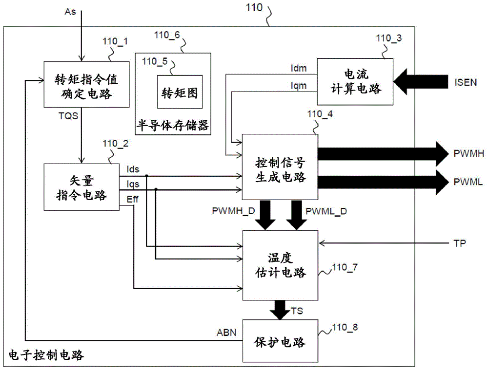
图5是示出根据第一实施例的电子控制电路110的详细配置示例的框图。除非另有说明,否则与图2中相同的附图标记的描述应当原则上适用于图2的描述。FIG. 5 is a block diagram showing a detailed configuration example of the
电子控制电路110中的转矩指令值确定电路110_1基于加速器指令值(因子)As,来计算和输出转矩指令值(因子)TQS,其指示作为要由电动机101输出的驱动量的转矩的大小。The torque command value determination circuit 110_1 in the
矢量指令电路110_2基于从转矩指令值确定电路110_1输入的转矩指令值TQS,来输出要提供给电动机101的电流值,以便输出期望转矩。基于dq坐标系,将要流向电动机101的电流指令值由作为电流矢量的d轴电流指令值Ids、以及q轴电流指令值Iqs这两个值给出。也就是说,将要流向电动机的电流的值由dq坐标系中的d轴电流指令值Ids和q轴电流指令值Iqs来表达,dq坐标系由电动机101的转子的磁体形成的磁通方向上的d轴、以及与d轴垂直的q轴方向组成,并且其与转子一起旋转。也就是说,矢量指令电路110_2获取或计算并且输出包括有d轴电流指令值Ids和q轴电流指令值Iqs的电流矢量。The vector command circuit 110_2 outputs the current value to be supplied to the
另外,当逆变器101由d轴电流指令值Ids和q轴电流指令值Iqs来驱动时,矢量指令电路110_2输出逆变器效率值Eff。In addition, when the
电流计算电路110_3从配置有诸如霍尔元件等电流检测元件的电流测量电路104u、104v、104w,来获取电动机101的三相电流测量值ISEN(ISENu、ISENv、ISENw)。基于所获取的三相电流测量值ISEN(ISENu、ISENv、ISENw),通过坐标变换等来计算包括有d轴电流测量值Idm和q轴电流测量值Iqm的电流矢量。The current calculation circuit 110_3 acquires three-phase current measurement values ISEN (ISENu, ISENv, ISENw) of the
控制信号生成电路110_4接收d轴电流测量值Idm、q轴电流测量值Iqm、d轴电流指令值Ids以及q轴电流指令值Iqs。此外,控制信号生成电路110_4执行PI(比例积分)控制,以使得d轴电流测量值Idm和q轴电流测量值Iqm相应地收敛于d轴电流指令值Ids和q轴电流指令值Iqs,并且控制信号生成电路110_4计算d轴电压指令值Vds和q轴电压指令值Vqs。The control signal generation circuit 110_4 receives the d-axis current measurement value Idm, the q-axis current measurement value Iqm, the d-axis current command value Ids, and the q-axis current command value Iqs. Further, the control signal generation circuit 110_4 performs PI (Proportional Integral) control such that the d-axis current measurement value Idm and the q-axis current measurement value Iqm converge to the d-axis current command value Ids and the q-axis current command value Iqs, respectively, and controls The signal generation circuit 110_4 calculates the d-axis voltage command value Vds and the q-axis voltage command value Vqs.
随后,控制信号生成电路110_4基于d轴电压指令值Vds和q轴电压指令值Vqs,通过诸如坐标变换等计算来计算用于驱动六个功率半导体元件102a至102f的占空比PWMH_D(Hu_D、Hv_D、Hw_D)和PWML_D(Lu_D、Lv_D、Lw_D)。Subsequently, the control signal generation circuit 110_4 calculates the duty ratio PWMH_D (Hu_D, Hv_D, Hu_D, Hv_D) for driving the six
此外,基于占空比PWMH_D(Hu_D、Hv_D、Hw_D)和PWML_D(Lu_D、Lv_D、Lw_D),通过PWM调制或其他计算来生成互补的三相电压信号PWMH(Hu、Hv、Hw)和PWML(Lu、Lv、Lw),作为用于驱动六个功率半导体元件102a至102f的栅极控制信号。三相电压信号PWMH(Hu、Hv、Hw)和PWML(Lu、Lv、Lw)是彼此互补的PWM信号,因此例如,当Hu处于高电平时,Lu处于低电平。In addition, based on the duty cycles PWMH_D (Hu_D, Hv_D, Hw_D) and PWML_D (Lu_D, Lv_D, Lw_D), complementary three-phase voltage signals PWMH (Hu, Hv, Hw) and PWML (Lu) are generated by PWM modulation or other calculations , Lv, Lw) as gate control signals for driving the six
但是,严格地说,为了防止由于同时激活功率半导体元件102a和102b而引起的布线短路,包括用于同时去激活功率半导体元件102a和102b的死区时间。互补的三相电压信号PWMH(Hu、Hv、Hw)和PWML(Lu、Lv、Lw)分别输出到栅极驱动电路111,并且成为栅极驱动电路111中的栅极驱动信号DPWMH(DHu、DHv、DHw)和DPWML(DLu、DLv、DLw)的生成源。Strictly speaking, however, in order to prevent a wiring short circuit due to simultaneous activation of the
在此,控制信号生成器110_4保存PWMH_D(Hu_D、Hv_D、Hw_D)和PWML_D(Lu_D、Lv_D、Lw_D),其分别是作为PWM信号的互补的三相电压信号PWMH(Hu、Hv、Hw)和PWML(Lu、Lv、Lw)的占空比。Here, the control signal generator 110_4 holds PWMH_D (Hu_D, Hv_D, Hw_D) and PWML_D (Lu_D, Lv_D, Lw_D), which are the complementary three-phase voltage signals PWMH (Hu, Hv, Hw) and PWML, respectively, as the PWM signals (Lu, Lv, Lw) duty cycle.
电流计算电路110_3基于三相电流测量值ISEN(ISENu、ISENv、ISENw)的时间变化的周期,来计算每单位时间的电动机转速REV。如上所描述,转速REV可以基于测量的电流值来计算,或者还可以基于诸如解析器的电动机旋转检测设备的输出来计算。The current calculation circuit 110_3 calculates the motor rotation speed REV per unit time based on the period of time change of the three-phase current measurement values ISEN (ISENu, ISENv, ISENw). As described above, the rotational speed REV may be calculated based on the measured current value, or may also be calculated based on the output of a motor rotation detection device such as a resolver.
在转矩图(map)110_5中,记录在特定转速REV和特定电动机驱动电压VBUS处,与转矩指令值相对应的d轴电流指令值Ids和q轴电流指令值Iqs,并且记录当逆变器101在这些电流条件下被驱动时的逆变器效率值Eff。逆变器效率值Eff是从逆变器101输出的功率与输入到逆变器101的功率的比值。换言之,逆变器效率值Eff是逆变器101的输出功率与逆变器101的输入功率的比值。In the torque map 110_5, the d-axis current command value Ids and the q-axis current command value Iqs corresponding to the torque command value at the specific rotational speed REV and the specific motor drive voltage VBUS are recorded, and when the inverter is reversed The inverter efficiency value Eff when the
例如,转矩图110_5被保存在电子控制电路110中的半导体存储器110_6中。例如,可以使用易失性或非易失性存储器设备作为半导体存储器110_6。半导体存储器110_6可以设置在电子控制电路110的外部。For example, the torque map 110_5 is stored in the semiconductor memory 110_6 in the
温度估计电路110_7基于互补的三相电压信号中的每个信号的占空比PWMH_D(Hu_D、Hv_D、Hw_D)、PWML_D(Lu_D、Lv_D、Lw_D)、d轴电流指令值Ids、q轴电流指令值Iqs、d轴电压指令值Vds、q轴电压指令值Vqs、温度测量值TP和逆变器效率值Eff,来估计功率半导体元件102a至102f的温度TS(TSa、TSb、TSc、TSd、TSe、TSf)。The temperature estimation circuit 110_7 is based on the duty ratio of each of the complementary three-phase voltage signals PWMH_D (Hu_D, Hv_D, Hw_D), PWML_D (Lu_D, Lv_D, Lw_D), d-axis current command value Ids, q-axis current command value Iqs, d-axis voltage command value Vds, q-axis voltage command value Vqs, temperature measurement value TP, and inverter efficiency value Eff to estimate the temperatures TS (TSa, TSb, TSc, TSd, TSe, TSf).
(温度估计方法)(Temperature estimation method)
温度估计电路110_7根据d轴电流指令值Ids、q轴电流指令值Iqs、d轴电压指令值Vds、q轴电压指令值Vqs和逆变器效率值Eff,来计算逆变器输出功率Pout和输入功率Pin。用于计算逆变器输出功率Pout和输入功率Pin的计算等式相应地由以下等式(1)和(2)来表达。The temperature estimation circuit 110_7 calculates the inverter output power Pout and the input from the d-axis current command value Ids, the q-axis current command value Iqs, the d-axis voltage command value Vds, the q-axis voltage command value Vqs, and the inverter efficiency value Eff Power Pin. The calculation equations for calculating the inverter output power Pout and the input power Pin are expressed by the following equations (1) and (2), respectively.
[等式1][Equation 1]
Pout=Ids×Vds+Iqs×Vqs P out =I ds ×V ds +I qs ×V qs
(1)(1)
[等式2][Equation 2]
Pin=Pout/Eff (2)P in =P out /Eff (2)
还可以根据基于逆变器输出电压的功率因子的三相的相电流和相电压,来计算逆变器输出电压Pout。The inverter output voltage Pout can also be calculated from the phase currents and phase voltages of the three phases based on the power factor of the inverter output voltage.
接下来,温度估计电路110_7根据逆变器输出功率Pout和输入功率Pin,来计算逆变器102的损耗ILOSS。用于计算逆变器102的损耗ILOSS的算术表达式由等式(3)表达如下。Next, the temperature estimation circuit 110_7 calculates the loss ILOSS of the
[等式3][Equation 3]
ILOSS=Pin-Pout (3)ILOSS=P in -P out (3)
由于逆变器102的损耗ILOSS主要消耗为热量,逆变器102的损耗ILOSS基本上对应于逆变器102的热量值。另外,由于逆变器102的损耗ILOSS主要由功率半导体元件102a至102f的总损耗SLOSS组成,所以逆变器102的热量生成量基本上对应于功率半导体元件102a至102f的总损耗SLOSS。此处,当逆变器102的损耗ILOSS中,除了功率半导体元件102a至102F的损耗之外的损耗被设为OLOSS时,用于计算功率半导体元件102a至102F的总损耗SLOSS的算术表达式由以下等式(4)来表达。Since the losses ILOSS of the
[等式4][Equation 4]
SLOSS=ILOSS-OLOSS (4)SLOSS=ILOSS-OLOSS (4)
此外,温度估计电路110_7通过基于功率半导体器件的数目和用于驱动功率半导体器件的栅极的信号的占空比来分配功率半导体器件102a至102f的总损耗SLOSS,从而计算功率半导体器件102a至102f的单个损耗SLOSSa至SLOSSf。由于用于驱动功率半导体元件102a至102f的栅极的信号的占空比由PWMH_D(Hu_D、Hv_D、Hw_D)和PWML_D(Lu_D、Lv_D、Lw_D)给出,因此用于计算单个损耗SLOSSa至SLOSSf的计算等式如下。在此,Ch是逆变器的通道数,并且在本实施例中,Ch=6。Further, the temperature estimation circuit 110_7 calculates the
[等式5][Equation 5]

功率半导体元件的温度上升量是基于功率半导体元件的损耗和热阻来确定的。热阻是温度上升量与生成的热量的比值,并且单位是[摄氏度/瓦特]。在本实施例中,用于计算功率半导体元件102a至102f的结部分的温度的热阻被设置为等于Rth。温度估计电路110_7通过由以下等式(6)表示的计算,来计算功率半导体元件102a至102f的温度TSa至TSf。The temperature rise amount of the power semiconductor element is determined based on the loss and thermal resistance of the power semiconductor element. Thermal resistance is the ratio of the temperature rise to the heat generated, and the unit is [Celsius/Watt]. In the present embodiment, the thermal resistance for calculating the temperature of the junction portion of the
[等式6][Equation 6]
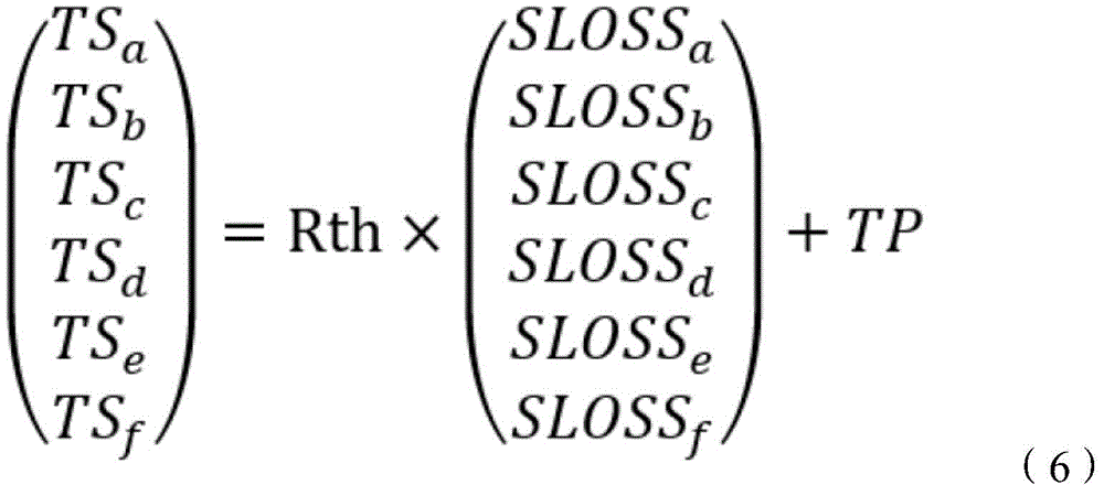
功率半导体元件102a至102f的热阻Rth通过测量或模拟而得知,并且该值被保存在电子控制单元110中。作为保存方法,例如,可以将数据存储在半导体存储器110_6中。功率半导体元件102a至102f的热阻Rth也可以通过在电子控制电路110中的计算来计算。The thermal resistance Rth of the
在本实施例的计算中,逆变器102的损耗ILOSS被计算为与功率半导体元件102a至102f的总损耗SLOSS相一致,但是计算中还可以包括构成逆变器的其他组件(诸如薄膜电容器、母线和放电电阻器)的损耗。在这种情况下,可以通过从逆变器102的损耗ILOSS中减去其他组件的损耗,来获取功率半导体元件102a至102f的总损耗SLOSS。In the calculation of this embodiment, the loss ILOSS of the
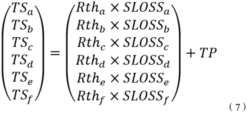
在本实施例的计算中,功率半导体元件102a至102f的热阻设置为等于Rth,但是通过预先获取功率半导体元件102a至102f的单个热阻Rtha至Rthf,可以考虑到功率半导体元件102a至102f的热阻的差异的情况下来执行该计算,该热阻的差异是由将功率半导体元件102a至102f安装在驱动系统100上的条件所引起的。当功率半导体元件102a至102f的温度TSa至TSf是通过使用单个热阻Rtha至Rthf来计算时,使用由以下公式(7)表达的计算公式。In the calculation of the present embodiment, the thermal resistances of the
[等式7][Equation 7]
(保护操作)(protection operation)
温度估计电路110_7将功率半导体元件102a至102f的计算的温度TS(TSa、TSb、TSc、TSd、TSe、TSf)输出给保护电路110_8。The temperature estimation circuit 110_7 outputs the calculated temperatures TS (TSa, TSb, TSc, TSd, TSe, TSf) of the
保护电路110_8输入功率半导体器件102a至102f的温度TSA至TSf,并且控制控制设备103以使得当确定任何功率半导体器件处于过热状态时,处于过热状态的功率半导体器件的驱动被停止并且器件迅速返回到正常状态(非过热状态)。在下文中,将描述用于实现控制方法的具体配置示例。The protection circuit 110_8 inputs the temperatures TSA to TSf of the
在本实施例中,保护电路110_8保存过热温度阈值Tth。过热温度阈值Tth指示确定功率半导体元件处于过热状态的基准温度,并且例如被设置为80摄氏度。保护电路110_8将功率半导体元件102a至102f的温度TSa至TSf中的每个温度与过热温度阈值Tth相比较。如果Tsa至TSf中的任何一个超过Tth,则保护电路110_8向转矩指令值确定电路110_1输出异常信号ABN,其指示逆变器102处于过热状态。当接收到异常信号ABN时,转矩指令值确定电路110_1输出零值作为转矩指令值TQS,以便停止驱动电动机101。具体地,查阅转矩图110_5,并且输出在TQS=0[Nm]处的电流指令值Ids=0[A]和Iqs=0[A]。结果,全部功率半导体元件102a至102f都没有电流流过,并且处于过热状态的功率半导体元件被冷却。In this embodiment, the protection circuit 110_8 saves the overheat temperature threshold Tth. The overheat temperature threshold value Tth indicates a reference temperature at which it is determined that the power semiconductor element is in an overheated state, and is set to 80 degrees Celsius, for example. The protection circuit 110_8 compares each of the temperatures TSa to TSf of the
将参考图6描述根据本实施例的驱动系统100的操作流程的一个示例。首先,计算与加速器指令值As相对应的转矩指令值TQS(步骤S101)。接着,使用计算出的转矩指令值TQS来计算d轴电流指令值Ids、q轴电流指令值Iqs、逆变器效率值Eff、d轴电压指令值Vds和q轴电压指令值Vqs(步骤S102)。接下来,基于d轴电压指令值Vds和q轴电压指令值Vqs,计算用于驱动六个功率半导体102a至102f的占空比PWMH_D(Hu_D、Hv_D、Hw_D)和PWML_D(Lu_D、Lv_D、Lw_D)(步骤S103)。接下来,基于占空比PWMH_D和PWML_D,生成三相电压信号PWMH(Hu、Hv、Hw)和PWML(Lu、Lv、Lw),并且通过驱动功率半导体元件102a至102f的栅极来操作逆变器102以驱动电动机101(步骤S104)。接下来,在步骤S105中,基于d轴电流指令值Ids、q轴电流指令值Iqs、逆变器效率值Eff、d轴电压指令值Vds和q轴电压指令值Vqs,来计算功率半导体器件102a至102f的总损耗SLOSS。然后,基于总损耗SLOSS、占空比PWMH_D,PWML_D、热阻Rth和测量温度值TP,来计算功率半导体元件102a至102f的温度TSa至TSf(步骤S106)。One example of the operation flow of the
将参考图7与驱动系统100的操作示例相关联地描述根据本实施例的电子控制电路110的一个操作示例。图7是示意性地示出根据第一实施例的电子控制电路110的操作的一个示例的时序图。首先,在状态(1)下,按下加速器踏板106,并且驱动系统100从电动机101不被转矩TQ1驱动的状态,进入到电动机101被转矩TQ2驱动的加速状态。在电动机的驱动期间,水温TP和功率半导体元件102a的温度TSa升高。接下来,在状态(2)下,加速器106的推动量减小,并且驱动系统100变为巡航状态,其基于减小的转矩TQ3来驱动电动机101。尽管与紧接在状态(2)的时刻相比,水温TP和功率半导体元件102a的温度TSa降低,但是电动机101的驱动继续,使得温度TSa逐渐升高。随后,在状态(3)和状态(4)下,分别通过与状态(1)和状态(2)相似的转矩指令值TQ2和TQ3驱动电动机101,但是因为电动机101继续被驱动直到紧接在状态(2)之前,水温TP和功率半导体元件102a的温度TSa上升。随后,在状态(5)下,再次按下加速器106,驱动系统100处于电动机101被转矩TQ2驱动的加速状态,并且水温TP和功率半导体元件102a的温度TSa开始进一步增加。接下来,在状态(6)下,保护电路110_8检测到功率半导体元件102a的温度TSa超过过热温度阈值Tth,并且输出异常信号ABN。转矩指令值确定电路110_1接收异常信号ABN,并且将转矩指令值设置为TQ1,使得在转矩TQ1驱动系统100不驱动电动机101。因此,当功率半导体元件102a的温度TSa达到过热温度阈值Tth时,电动机101的驱动停止,并且处于过热状态的功率半导体元件102a可以被冷却。One operation example of the
本实施例的主要效果如下。根据本实施例的驱动系统100包括温度估计电路110_7。温度估计电路110_7获取与转矩指令值TQS相对应的逆变器的效率值Eff,并且基于效率值Eff来计算整个逆变器的损耗ILOSS。随后,温度估计电路110_7基于用于驱动功率半导体元件中的每个功率半导体元件的占空比PWMH_D和PWML_D,来执行用于将整个逆变器的损耗ILOSS的分解分配到构成逆变器102的、功率半导体元件102a至102f中的每个功率半导体元件的计算,从而获取功率半导体元件102a至102f中的每个功率半导体元件的损耗SLOSSa至SLOSSf。然后,温度估计电路110_7通过基于每个功率半导体元件的损耗和已知的热阻值的计算,来计算功率半导体元件的温度TSa至TSf。The main effects of this embodiment are as follows. The
利用这样的配置,通过基于逆变器102的功率效率值Eff来计算功率半导体元件的损耗SLOSSa至SLOSSf,可以高速且高准度地估计功率半导体元件102a至102f的温度TSa至TSf。With such a configuration, by calculating the losses SLOSSa to SLOSSf of the power semiconductor elements based on the power efficiency value Eff of the
当确定功率半导体元件中的任何功率半导体元件的温度处于过热状态时,通过保护电路110_8的功能停止电动机101的驱动,并且处于过热状态的功率半导体元件被冷却,因此驱动系统100可以免于故障或着火。When it is determined that the temperature of any of the power semiconductor elements is in an overheated state, the driving of the
在配备有自动驾驶系统的车辆的情况下,自动驾驶系统可以生成加速器指令值(因子)As和转矩指令值(因子)TQS,并且将其输出给控制设备103,而与加速器踏板106的状态无关。In the case of a vehicle equipped with an automatic driving system, the automatic driving system may generate an accelerator command value (factor) As and a torque command value (factor) TQS, and output them to the
(转矩图的配置示例)(Configuration example of torque diagram)
图8示出了在转速REV=950[rpm]并且电动机驱动电压VBUS=300[V]的条件下的转矩图。在该转矩图中,记录了与转矩(Torque)相对应的d轴电流Id、q轴电流Iq和效率(Efficiency)。例如,当转矩指令值TQS是54.0[Nm]时,对应的d轴电流指令值Ids为-29.62[A],q轴电流指令值Iqs为81.38[A],并且逆变器的效率值Eff为93.6[%]。FIG. 8 shows a torque diagram under the conditions of the rotational speed REV=950 [rpm] and the motor drive voltage VBUS=300 [V]. In this torque map, the d-axis current Id, the q-axis current Iq, and the efficiency (Efficiency) corresponding to the torque (Torque) are recorded. For example, when the torque command value TQS is 54.0 [Nm], the corresponding d-axis current command value Ids is -29.62 [A], the q-axis current command value Iqs is 81.38 [A], and the inverter efficiency value Eff is 93.6[%].
半导体存储器110_6存储多个模式的转矩图110_5,其与其他转速REV和电动机驱动电压VBUS的组合相对应。当转速REV和电动机驱动电压VBUS改变时,转矩图110_5适当地改变为对应值。The semiconductor memory 110_6 stores a plurality of patterns of torque maps 110_5 corresponding to other combinations of the rotational speed REV and the motor drive voltage VBUS. When the rotational speed REV and the motor driving voltage VBUS are changed, the torque map 110_5 is appropriately changed to the corresponding value.
当转速REV和电动机驱动电压VBUS不对应于任何转矩图110_5时,矢量指令电路110_2可以采用存在于该多个模式的转矩图110_5中的、并且最接近于该值的值。此外,通过使用诸如线性插值或多项式插值等插值方法,可以计算对应的转矩指令值、d轴电流指令值Ids、q轴电流指令值Iqs和逆变器效率值Eff。When the rotational speed REV and the motor drive voltage VBUS do not correspond to any torque map 110_5, the vector command circuit 110_2 may take a value that exists in the torque map 110_5 of the plurality of modes and is closest to the value. Furthermore, by using an interpolation method such as linear interpolation or polynomial interpolation, the corresponding torque command value, d-axis current command value Ids, q-axis current command value Iqs, and inverter efficiency value Eff can be calculated.
矢量指令电路110_2使用从转矩指令值确定电路110_1输入的转矩指令值TQS和转矩图110_5,来输出d轴电流指令值Ids和q轴电流指令值Iqs作为将要流到电动机101的电流值,以使电动机101输出期望转矩。The vector command circuit 110_2 uses the torque command value TQS input from the torque command value determination circuit 110_1 and the torque map 110_5 to output the d-axis current command value Ids and the q-axis current command value Iqs as current values to flow to the
如果转矩指令值TQS是转矩图110_5中不存在的数值,则矢量指令电路110_2可以基于转矩图110_5中存在的值,来采用最接近的值。作为另一种方法,通过使用诸如线性插值或多项式插值等插值方法,可以计算与转矩指令值相对应的d轴电流指令值Ids、q轴电流指令值Iqs和逆变器的效率值Eff。If the torque command value TQS is a value not present in the torque map 110_5, the vector command circuit 110_2 may take the closest value based on the value present in the torque map 110_5. As another method, by using an interpolation method such as linear interpolation or polynomial interpolation, the d-axis current command value Ids, the q-axis current command value Iqs, and the inverter efficiency value Eff corresponding to the torque command value can be calculated.
此外,根据本实施例的驱动系统100可以在电动机101被供电,即在转矩指令值TQS为正时、以及在电动机101再生(regenerate),即在转矩指令值TQS为负时,来估计功率半导体元件102a至102f的温度TSa至TSf。Further, the
(栅极驱动电路111的配置示例)(Configuration example of gate drive circuit 111 )
图9示出了根据第一实施例的栅极驱动电路111的一个配置示例。栅极驱动电路111设置在电子控制电路110与逆变器102之间。栅极驱动电路111包括隔离器111_1a至111_1f以及预驱动器111_2a至111_2f,隔离器111_1a至111_1f用于通过磁耦合来传输和接收信号,同时将逆变器102与控制设备103电隔离,预驱动器111_2a至111_2f用于驱动功率半导体器件102a至102f的栅极。FIG. 9 shows one configuration example of the
预驱动器111_2a至111_2f基于互补的三相电压信号PWMH(Hu、Hv、Hw)和PWML(Lu、Lv、Lw)来相应地输出用于控制相应的功率半导体元件(102a、102c、102e)和(102b、102d、102f)的栅极的栅极驱动信号DPWMH(DHu、DHv、DHw)和DPWML(DLu、DLv、DLw)。The pre-drivers 111_2a to 111_2f output corresponding outputs for controlling the corresponding power semiconductor elements (102a, 102c, 102e) and ( 102b, 102d, 102f) gate drive signals DPWMH (DHu, DHv, DHw) and DPWML (DLu, DLv, DLw).
由于栅极驱动电路111具有将由诸如MCU等低压器件形成的电子控制电路110与由功率器件形成的逆变器102绝缘的功能,所以栅极驱动电路111优选地由独立于电子控制电路110和逆变器102的半导体器件形成。在根据第一实施例的栅极驱动电路111中,隔离器111_1a至111_1f和预驱动器111_2a至111_2f成对被安装在驱动半导体器件111_3a至111_3f中的每一者中。Since the
(功率半导体元件102a至102f的配置示例)(Configuration example of
图10示出了功率半导体元件102a的一个配置示例。功率半导体102b至102f具有与图10所示的功率半导体元件102a相同的配置。功率半导体102a包括绝缘栅双极晶体管(IGBT)102a_1和快速恢复二极管(FRD)102a_2。当电流流过IGBT 102a_1时,IGBT 102a_1生成热量。当电流流过FRD 102a_2时,FRD 102a_2生成热量。FIG. 10 shows one configuration example of the
也就是说,IGBT 102a_1的热量生成取决于电压信号Hu的占空比Hu_D,而FRD102a_2的热量生成取决于电压信号Hu的(1-Hu_D)。因此,可以通过使用(1-Hu_D)而不是使用占空比Hu_D,来估计FRD 102a_2的损耗SLOSS_FRD以估计温度。另外,如果已知FRD 102a_2的热阻Rth_FRD,则还可以估计FRD102a_2的结温TSa_FRD。通过将上述FRD 102a_2的温度估计方法应用于功率半导体102b至102f的FRD 102b_2至102f_2,可以估计六个FRD 102a_2至102f_2的温度TS_FRD(TSa_FRD、TSb_FRD、TSc_FRD、TSd_FRD、TSe_FRD、TSf_FRD)。That is, the heat generation of the IGBT 102a_1 depends on the duty ratio Hu_D of the voltage signal Hu, and the heat generation of the FRD 102a_2 depends on (1-Hu_D) of the voltage signal Hu. Therefore, the loss SLOSS_FRD of the FRD 102a_2 can be estimated by using (1-Hu_D) instead of using the duty cycle Hu_D to estimate the temperature. Additionally, if the thermal resistance Rth_FRD of the FRD 102a_2 is known, the junction temperature TSa_FRD of the FRD 102a_2 can also be estimated. By applying the above-described temperature estimation method of the FRD 102a_2 to the FRDs 102b_2 to 102f_2 of the
(实施例1的修改)(Modification of Example 1)
图11是在根据第一实施例的电子控制电路110的修改中的温度估计模式的一个配置示例。相比之下,图5的电子控制电路110是正常操作模式的一个配置示例。也就是说,由于电子控制电路110的功能通过使用处理器的程序来实现,所以可以根据操作模式的改变来改变组件及其连接关系。FIG. 11 is one configuration example of the temperature estimation mode in the modification of the
在本修改中,当功率半导体元件102a至102f的温度TSa至TSf中的任何一个温度超过过热温度阈值Tth时,电子控制电路110临时假定图11所示的温度估计模式的配置。在具有图11的配置的电子控制电路110中,矢量指令电路110_2输入由虚拟转矩指令电路110_9生成的虚拟(初步的、伪的)转矩值TQSV来代替转矩指令值TQS。虚拟转矩TQSV独立于驱动逆变器102的信号。In the present modification, when any one of the temperatures TSa to TSf of the
电子控制电路110假定逆变器102由虚拟转矩TQSV驱动,并且通过温度估计电路110_7以与第一实施例相同的方式来估计功率半导体元件102a至102f的虚拟温度TSV(TSVa、TSVb、TSVc、TSVd、TSVe、TSVf)。另一方面,基于虚拟转矩TQSV而生成的信号不被输出到栅极驱动器111。The
例如,电子控制电路110将转矩指令值TQS的1/2的值设置为虚拟转矩值TQSV,并且当虚拟温度TSVa至TSVf未超过过热温度阈值Tth时,向转矩指令值确定电路110_1传输虚拟转矩值TQSV,作为在避免了过热的操作范围内的容许转矩。转矩指令值确定电路110_1采用不基于加速器指令值As的虚拟转矩指令值TQSV的值作为转矩指令值TQS。此后,电子控制电路110返回到图5所示的正常模式,并且执行第一实施例中说明的驱动控制。For example, the
如果即使将转矩指令值TQS的1/2的值用作虚拟转矩值TQSV,虚拟温度TSVa至TSVf仍然超过过热温度阈值Tth,则将虚拟转矩值TQSV逐渐减小至转矩指令值TQS的1/3的值和1/4的值,并且基于这些值依次计算虚拟温度TSVa至TSVf。然后,采用在获取到虚拟温度TSVa至TSVf不超过过热温度阈值Tth的时间点处的虚拟转矩值TQSV,作为转矩指令值TQS的值。If the virtual temperatures TSVa to TSVf exceed the overheat temperature threshold value Tth even if a value of 1/2 of the torque command value TQS is used as the virtual torque value TQSV, the virtual torque value TQSV is gradually decreased to the torque
本修改特有的效果如下。即,即使当功率半导体元件102a至102f的温度TSa至TSf中的任何一个温度超过过热温度阈值Tth时,电子控制电路110也可以执行控制,以在防止过热的同时,维持逆变器102的驱动并且允许车辆继续运行。Effects specific to this modification are as follows. That is, even when any one of the temperatures TSa to TSf of the
[实施例2][Example 2]
接下来,将描述实施例2。在第二实施例中,将描述电子控制电路110a,其是根据第一实施例的电子控制电路110的另一种形式。图12是示出根据第二实施例的电子控制电路110a的一个配置示例的图。在实施例2中,除了电子控制电路110a之外的配置可以与实施例1中的配置相同。实施例1的描述原则上适用于与实施例1具有相同附图标记的电子控制电路110a的内部配置。Next,
如图12所示,与根据实施例1的电子控制电路110相比,在根据第二实施例的电子控制电路110a中,增加了转矩管理电路110_10、信号生成/温度估计电路110_11、虚拟矢量指令电路110_12和温度管理电路110_13。转矩指令值确定电路110_1、控制信号生成电路110_4、温度估计电路110_7和保护电路110_8被移除。As shown in FIG. 12 , in the
转矩管理电路110_10基于加速器指令值As计算转矩指令值TQS,其表示将要由电动机101输出的转矩,并且将该转矩指令值TQS输出到矢量指令电路110_2。The torque management circuit 110_10 calculates a torque command value TQS, which represents the torque to be output by the
此外,转矩管理电路110_10在假定逆变器102以任意转矩被驱动的情况下,计算虚拟转矩值TQS_vt,并且将计算出的值输出到虚拟矢量指令电路110_12。Further, the torque management circuit 110_10 calculates a virtual torque value TQS_vt under the assumption that the
基于从转矩指令值确定电路110_1输入的转矩指令值TQS,矢量指令电路110_2向信号生成/温度估计电路110_11输出d轴电流指令值Ids、q轴电流指令值Iqs以及当电动机101在这些电流条件下被驱动时的逆变器效率值Eff。Based on the torque command value TQS input from the torque command value determination circuit 110_1, the vector command circuit 110_2 outputs the d-axis current command value Ids, the q-axis current command value Iqs, and when the
基于从转矩指令值确定电路110_1输入的虚拟转矩指令值TQS_vt,虚拟矢量指令电路110_2向信号生成/温度估计电路110_11输出虚拟d轴电流指令值Ids_vt、虚拟q轴电流指令值Iqs_vt以及当电动机101在这些电流条件下被驱动时的虚拟逆变器效率值Eff_vt。Based on the virtual torque command value TQS_vt input from the torque command value determination circuit 110_1, the virtual vector command circuit 110_2 outputs the virtual d-axis current command value Ids_vt, the virtual q-axis current command value Iqs_vt, and the current command value Iqs_vt when the motor is generated to the signal generation/temperature estimation circuit 110_11 101 The virtual inverter efficiency value Eff_vt when driven under these current conditions.
信号生成/温度估计电路110_11包括根据第一实施例的控制信号生成电路110_4和温度估计电路110_7的功能。也就是说,基于d轴电流测量值Idm和q轴电流测量值Iqm以及d轴电流指令值Ids和q轴电流指令值Iqs,以与第一实施例相同的方式来生成互补的三相电压信号PWMH(Hu、Hv、Hw)和PWML(Lu、Lv、Lw)。此外,基于互补的三相电压信号PWMH_D(Hu_D、Hv_D、Hw_D)、PWML_D(Lu_D、Lv_D、Lw_D)的占空比、d轴电流指令值Ids、q轴电流指令值Iqs、d轴电压指令值Vds、q轴电压指令值Vqs、温度测量值TP以及逆变器效率Eff,来估计功率半导体102a至102f的温度TS(TSa、TSb、TSc、TSd、TSe、TSf)。The signal generation/temperature estimation circuit 110_11 includes the functions of the control signal generation circuit 110_4 and the temperature estimation circuit 110_7 according to the first embodiment. That is, based on the d-axis current measurement value Idm and the q-axis current measurement value Iqm and the d-axis current command value Ids and the q-axis current command value Iqs, the complementary three-phase voltage signals are generated in the same manner as in the first embodiment PWMH (Hu, Hv, Hw) and PWML (Lu, Lv, Lw). In addition, based on the complementary three-phase voltage signals PWMH_D (Hu_D, Hv_D, Hw_D), duty ratio of PWML_D (Lu_D, Lv_D, Lw_D), d-axis current command value Ids, q-axis current command value Iqs, d-axis voltage command value The temperatures TS (TSa, TSb, TSc, TSd, TSe, TSf) of the
信号生成/温度估计电路110_11基于d轴电流测量值Idm、q轴电流测量值Iqm、虚拟d轴电流测量值Ids_vt、虚拟q轴电流测量值Iqs_vt、温度测量值TP和虚拟逆变器效率值Eff_vt来估计功率半导体器件102a至102f的虚拟温度TS_vt(TSa_vt、TSb_vt、TSc_vt、TSd_vt、TSe_vt、TSf_vt)。The signal generation/temperature estimation circuit 110_11 is based on the d-axis current measurement value Idm, the q-axis current measurement value Iqm, the virtual d-axis current measurement value Ids_vt, the virtual q-axis current measurement value Iqs_vt, the temperature measurement value TP, and the virtual inverter efficiency value Eff_vt to estimate the virtual temperatures TS_vt (TSa_vt, TSb_vt, TSc_vt, TSd_vt, TSe_vt, TSf_vt) of the
温度管理电路110_13包括根据第一实施例的保护电路110_8的功能。也就是说,温度管理电路110_13保存过热温度阈值Tth,并且当TSa至TSf中的任何一项超过Tth时,向转矩管理电路110_10输出指示逆变器102处于过热状态的异常信号ABN。当接收到异常信号ABN时,转矩管理电路110_10输出零值作为转矩指令值TQS,以便停止驱动电动机101。具体地,参考转矩图110_5,并且输出TQS=0[Nm]的电流指令值Ids=0[A]和Iqs=0[A]。结果,全部功率半导体元件102a至102f都没有电流流过,并且处于过热状态的功率半导体元件被冷却。The temperature management circuit 110_13 includes the functions of the protection circuit 110_8 according to the first embodiment. That is, the temperature management circuit 110_13 holds the overheat temperature threshold value Tth, and when any one of TSa to TSf exceeds Tth, outputs an abnormal signal ABN indicating that the
此外,在假定电动机101被虚拟转矩指令值TQS_vt驱动的情况下,当TSa_vt至TSf_vt中的任何一个超过Tth时,温度管理电路110_13向转矩管理电路110_10输出指示逆变器102处于过热状态的虚拟异常信号ABN_vt。当接收到异常信号ABN_vt时,转矩管理电路110_10控制转矩管理电路110_10以便不输出超过虚拟转矩指令值TQS_vt的值来作为转矩指令值TQS。Furthermore, assuming that the
具体地,转矩管理电路110_10包括限制电路110_10_1。限制电路110_10_1将转矩指令值TQS与转矩限制值TQS_limit相比较,并且当转矩指令值TQS超过转矩限制值TQS_limit时,输出转矩限制值TQS_limit作为转矩指令值TQS。当虚拟转矩指令值TQS_vt被设置为转矩限制值TQS_limit时,不管加速器指令值As的值如何,转矩管理电路110_10都不输出超过虚拟转矩指令值TQS_vt的转矩指令值TQS。Specifically, the torque management circuit 110_10 includes a limit circuit 110_10_1. The limit circuit 110_10_1 compares the torque command value TQS with the torque limit value TQS_limit, and when the torque command value TQS exceeds the torque limit value TQS_limit, outputs the torque limit value TQS_limit as the torque command value TQS. When the virtual torque command value TQS_vt is set as the torque limit value TQS_limit, regardless of the value of the accelerator command value As, the torque management circuit 110_10 does not output the torque command value TQS exceeding the virtual torque command value TQS_vt.
当响应于可选虚拟转矩指令值TQS_vt的输出,而接收到虚拟误差信号ABN_vt时,转矩管理电路110_10输出逐渐减小的虚拟转矩指令值TQS_vt。然后,采用在不再输出虚拟异常信号ABN_vt的时间点处的虚拟转矩指令值TQS_vt,作为转矩限制值TQS_limit。When receiving the virtual error signal ABN_vt in response to the output of the selectable virtual torque command value TQS_vt, the torque management circuit 110_10 outputs the gradually decreasing virtual torque command value TQS_vt. Then, the virtual torque command value TQS_vt at the point in time when the virtual abnormal signal ABN_vt is no longer output is employed as the torque limit value TQS_limit.
当响应于任意虚拟转矩指令值TQS_vt的输出,而没有接收到虚拟异常信号ABN_vt时,转矩管理电路110_10在逐渐增加虚拟转矩指令值TQS_vt的同时,顺序地输出虚拟转矩指令值TQS_vt。然后,采用在虚拟异常信号ABN_vt被输出的时间点处的虚拟转矩指令值TQS_vt,作为转矩限制值TQS_limit。When the virtual abnormal signal ABN_vt is not received in response to the output of any virtual torque command value TQS_vt, the torque management circuit 110_10 sequentially outputs the virtual torque command value TQS_vt while gradually increasing the virtual torque command value TQS_vt. Then, the virtual torque command value TQS_vt at the point in time when the virtual abnormal signal ABN_vt is output is adopted as the torque limit value TQS_limit.
另外,信号生成/温度估计电路110_11具有计算容许逆变器损耗ILOSS_max的功能,在该容许逆变器损耗ILOSS_max处逆变器101不过热。由以下式(8)表示用于计算容许逆变器损耗ILOSS_max的运算表达式。In addition, the signal generation/temperature estimation circuit 110_11 has a function of calculating the allowable inverter loss ILOSS_max at which the
[等式8][Equation 8]
ILOSS_max=(Tth-TP)/(Rth×Ch)+OLOSS (8)ILOSS_max=(T th -TP)/(Rth×Ch)+OLOSS (8)
信号生成/温度估计电路110_11基于从矢量指令电路110_2输入的d轴电流指令值Ids和q轴电流指令值Iqs、以及当电动机101在这些电流条件下被驱动时的逆变器效率值Eff,以与第一实施例中相同的方式来计算逆变器102的损耗ILOSS。然后,将逆变器损耗ILOSS与容许逆变器损耗ILOSS_max相比较,并且当逆变器损耗ILOSS超过容许逆变器损耗ILOSS_max时,向转矩管理电路110_10输出异常信号ABN_ls,异常信号ABN_ls指示转矩指令值TQS是会引起足以使逆变器102变得过热的损耗的数值。当输入异常信号ABN_ls时,转矩管理电路110_10以与输入异常信号ABN或异常信号ABN_vt时相同的方式,来执行电动机驱动的停止控制和转矩限制的控制。The signal generation/temperature estimation circuit 110_11 is based on the d-axis current command value Ids and the q-axis current command value Iqs input from the vector command circuit 110_2, and the inverter efficiency value Eff when the
本实施例的主要效果如下。电子控制电路110a可以在虚拟驱动条件下估计功率半导体元件102a至102f的虚拟温度TS_vt(TSa_vt、TSb_vt、TSc_vt、TSe_vt、TSf_vt),同时在驱动逆变器102的条件下估计功率半导体元件102a至102f的温度TS(TSa、TSb、TSc、TSd、TSe、TSf)。另外,可以计算逆变器102不会过热的最大容许逆变器损耗ILOSS_max,将其通知给转矩管理电路110_10,并且可以在转矩管理电路110_10中限制输出转矩。The main effects of this embodiment are as follows. The
转矩管理电路110_10中的输出转矩的限制可以结合车辆或驱动系统100中的其他条件和元件来实现。例如,转矩限制值TQS_limit可以根据电池108的剩余量来设置。The limitation of the output torque in the torque management circuit 110_10 may be implemented in conjunction with other conditions and elements in the vehicle or
[实施例3][Example 3]
接下来,将描述实施例3。在实施例3中,将描述电子控制电路110b,其作为根据实施例1的电子控制电路110的另一种形式。图13是示出根据第三实施例的电子控制设备110b的一个配置示例的图。在实施例3中,除了电子控制电路110b之外的配置可以与实施例1中的相同。实施例1的描述原则上适用于与实施例1具有相同附图标记的电子控制电路110b的内部配置。Next,
如图13所示,与根据第一实施例的电子控制电路110相比,根据第三实施例的电子控制电路110b包括用于代替温度估计电路110_7的温度估计电路110_7b、以及用于代替保护电路110_8的保护电路110_8b。As shown in FIG. 13 , compared with the
根据本实施例的温度估计电路110_7b具有估计在以转矩指令值TQS驱动电动机101、且经过任意时间之后的功率半导体元件102a至102f的温度的功能。从保护电路110_8b输入用作温度估计基准的经过时间Elap给温度估计电路110_7b。然后,估计在已经经过了经过时间Elap后、功率半导体元件102a至102f的温度TS_elap(TSa_elap、TSb_elap、TSc_elap、TSd_elap、TSe_elap、TSf_elap),并且将温度TS_elap输出到保护电路110_8b。在下文中,将描述用于实现温度估计的一个具体配置示例。The temperature estimation circuit 110_7b according to the present embodiment has a function of estimating the temperature of the
保护电路110_8b将经过时间Elap输出给温度估计电路110_7b,以便获取功率半导体元件102a至102f的估计的温度值TSa_elap至TSf_elap,TSa_elap至TSf_elap是从通过转矩TQS持续驱动电动机101以来,经过了经过时间Elap时的估计的温度值。The protection circuit 110_8b outputs the elapsed time Elap to the temperature estimation circuit 110_7b in order to obtain the estimated temperature values TSa_elap to TSf_elap of the
尽管根据第一实施例的温度估计电路110_7使用热阻Rth用于温度估计,但是根据第三实施例的温度估计电路110_7b使用瞬态热阻Rth_trans用于温度估计。瞬态热阻Rth_trans是随着热量生成时间热阻中的变化,并且在本实施例中,用于计算功率半导体元件102a至102f的结部分的温度的瞬态热阻相等地是Rth_trans。While the temperature estimation circuit 110_7 according to the first embodiment uses the thermal resistance Rth for temperature estimation, the temperature estimation circuit 110_7b according to the third embodiment uses the transient thermal resistance Rth_trans for temperature estimation. The transient thermal resistance Rth_trans is a change in thermal resistance with heat generation time, and in the present embodiment, the transient thermal resistance used to calculate the temperature of the junction portion of the
图14示出了瞬态热阻Rth_trans的一个示例。横坐标表示热量生成时间[s],纵坐标表示热阻[摄氏度/瓦特]。此处,如果将经过时间Elap处的热阻描述为Rth_trans(Elap),则在热量生成持续1秒时,即在Elap=1(1.0E+00)时的热阻Rth_trans(Elap)约为0.15[摄氏度/瓦],并且在热量生成持续10秒时,即在Elap=10(1.0E+0.1)时的热阻Rth_trans(Elap)约为0.22[摄氏度/瓦]。Figure 14 shows an example of the transient thermal resistance Rth_trans. The abscissa represents the heat generation time [s] and the ordinate represents the thermal resistance [degrees Celsius/Watt]. Here, if the thermal resistance at the elapsed time Elap is described as Rth_trans(Elap), the thermal resistance Rth_trans(Elap) when the heat generation lasts for 1 second, that is, when Elap=1(1.0E+00), is about 0.15 [degrees Celsius/Watt], and the thermal resistance Rth_trans(Elap) when the heat generation lasts for 10 seconds, ie, at Elap=10(1.0E+0.1), is about 0.22 [degrees Celsius/Watt].
基于输入的经过时间Elap,温度估计电路110_7b计算在电动机101继续由转矩指令值TQS驱动后经过了经过时间Elap时的热阻Rth-trans(Elap)。Based on the input elapsed time Elap, the temperature estimation circuit 110_7b calculates the thermal resistance Rth-trans(Elap) when the elapsed time Elap has elapsed after the
温度估计电路110_7通过以下等式(9)获取功率半导体元件102a至102f的温度TS_elap(TSa_elap、TSb_elap、TSc_elap、TSd_elap、TSe_elap、TSf_elap),其是在以转矩指令值TQS驱动电动机101后、已经经过了经过时间Elap时的时间点处的温度。The temperature estimation circuit 110_7 acquires the temperatures TS_elap (TSa_elap, TSb_elap, TSc_elap, TSd_elap, TSe_elap, TSf_elap) of the
[等式9][Equation 9]

功率半导体元件102a至102f的瞬态热阻Rth_trans通过测量或模拟来得知,并且该值被保存在电子控制电路110b中。作为保存方法,例如,可以将数据存储在半导体存储器110_6中。功率半导体元件102a至102f的瞬态热阻Rth_trans也可以在电子控制电路110b中计算。The transient thermal resistance Rth_trans of the
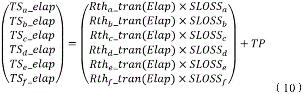
此外,在本实施例的计算中,功率半导体元件102a至102f的瞬态热阻等于Rth_trans,但是通过预先获取功率半导体元件102a至102f的单个瞬态热阻Rtha_trans至Rthf_trans,则可以考虑到功率半导体元件102a至102f的瞬态热阻的差异来执行该计算,瞬态热阻的差异是由将功率半导体元件102a至102f安装在驱动系统100上的条件所引起的。在使用单个热阻Rtha_trans至Rthf_trans,来计算当经过了经过时间Elap时的、功率半导体元件102a至102f的温度TSa_elap至TSf_elap的情况下,使用由以下表达式(10)表示的算术表达式。In addition, in the calculation of this embodiment, the transient thermal resistances of the
[等式10][Equation 10]
保护电路110_8b输入当从通过转矩TQS连续驱动电动机101起已经经过了经过时间Elap时的、功率半导体元件102a至102f的温度TSa_elap至TSf_elap。保护电路110_8b将温度TSa_elap至TSf_elap中的每个温度与过热温度阈值Tth相比较。当温度TSa_elap至TSf_elap中的任何一个温度超过Tth时,保护电路110_8向转矩指令值确定电路110_1输出异常信号ABN_elap,其指示在当前驱动条件下、经过了经过时间Elap时的逆变器102处于过热状态。当接收到异常信号ABN_elap时,转矩指令值确定电路110_1停止驱动电动机101。另外,可以通过与第二实施例的限制电路110_10_1相同的配置和方法,在不停止电动机101的驱动的情况下来限制输出转矩。The protection circuit 110_8b inputs the temperatures TSa_elap to TSf_elap of the
将参考图15,与驱动系统100的操作示例相关联地描述根据本实施例的电子控制电路110b的一个操作示例。图15是示意性地示出根据第三实施例的电子控制电路110b的操作的一个示例的时序图。从状态(1)到状态(5)的描述与相关于第一实施例的图7的描述相同。接下来,在状态(6)下,保护电路110_8b检测到在经过了经过时间Elap时的、功率半导体元件102a的温度TSa_elap超过过热温度阈值Tth,并且输出异常信号ABN_elap。已经接收到异常信号ABN_elap的转矩指令值确定电路110_1通过控制输出转矩,来将转矩指令值从TQ2切换到TQ4,以限制输出转矩。这可以在功率半导体元件102a的温度TSa达到过热温度阈值Tth之前,防止功率半导体元件102a的过热。With reference to FIG. 15 , one operation example of the
本实施例的主要效果如下。根据本实施例的驱动系统100可以通过使用功率半导体元件的瞬态热电阻Rth_trans用于温度估计,来估计当从转矩TQS持续驱动电动机101起、经过了经过时间Elap时的功率半导体元件102a至102f的温度TSa_elap至TSf_elap。The main effects of this embodiment are as follows. The
根据该配置,由于可以基于未来的预测来执行控制,因此可以在逆变器102达到过热状态之前执行保护操作。因此,驱动系统100可以基于任意的安全余量,来执行用于防止故障或着火的控制。According to this configuration, since the control can be performed based on the future prediction, the protection operation can be performed before the
尽管已经基于实施例具体描述了发明人做出的发明,但是本发明不限于已经描述的实施例,并且在不脱离其主旨的情况下可以进行各种修改。Although the invention made by the inventors has been specifically described based on the embodiments, the present invention is not limited to the described embodiments, and various modifications can be made without departing from the gist thereof.
Claims (20)
Applications Claiming Priority (2)
| Application Number | Priority Date | Filing Date | Title |
|---|---|---|---|
| JP2018238768A JP7061060B2 (en) | 2018-12-20 | 2018-12-20 | Control circuit, drive system and inverter control method |
| JP2018-238768 | 2018-12-20 |
Publications (2)
| Publication Number | Publication Date |
|---|---|
| CN111355440A true CN111355440A (en) | 2020-06-30 |
| CN111355440B CN111355440B (en) | 2023-11-07 |
Family
ID=71098132
Family Applications (1)
| Application Number | Title | Priority Date | Filing Date |
|---|---|---|---|
| CN201911141100.5A Active CN111355440B (en) | 2018-12-20 | 2019-11-20 | Control circuit, electric drive system, inverter system and control method thereof |
Country Status (3)
| Country | Link |
|---|---|
| US (1) | US11025157B2 (en) |
| JP (1) | JP7061060B2 (en) |
| CN (1) | CN111355440B (en) |
Families Citing this family (11)
| Publication number | Priority date | Publication date | Assignee | Title |
|---|---|---|---|---|
| EP3627121B1 (en) * | 2018-09-21 | 2022-07-06 | Maschinenfabrik Reinhausen GmbH | Determining a characteristic temperature of an electric or electronic system |
| KR102799714B1 (en) * | 2020-04-03 | 2025-04-25 | 현대자동차주식회사 | An electrical power conversion system and control method thereof |
| JP7472663B2 (en) * | 2020-06-05 | 2024-04-23 | 富士電機株式会社 | Power Conversion Equipment |
| GB2602338B (en) * | 2020-12-23 | 2023-03-15 | Yasa Ltd | A Method and Apparatus for Cooling One or More Power Devices |
| US12047023B2 (en) | 2021-08-11 | 2024-07-23 | Renesas Electronics Corporation | Torque map generation system |
| WO2023023991A1 (en) * | 2021-08-25 | 2023-03-02 | 宁德时代新能源科技股份有限公司 | Control method, apparatus and system for electric motor, and electric vehicle |
| US11716014B2 (en) * | 2021-12-27 | 2023-08-01 | GM Global Technology Operations LLC | Method for detecting early degradation within the inverter module |
| US12222738B2 (en) * | 2022-02-01 | 2025-02-11 | Ford Global Technologies, Llc | Method and system for controlling electric drive system according to predicted temperature of DC-link capacitor to prevent overheating |
| US12267989B2 (en) | 2022-02-10 | 2025-04-01 | Ford Global Technologies, Llc | Method and system for controlling electric drive system according to predicted temperature of inverter busbar |
| DE102023208654A1 (en) * | 2023-09-07 | 2025-03-13 | Zf Friedrichshafen Ag | Condition monitoring of a power semiconductor module |
| CN120415060A (en) * | 2024-01-31 | 2025-08-01 | 台达电子工业股份有限公司 | Power supply device, electrical system and temperature measurement method thereof |
Citations (5)
| Publication number | Priority date | Publication date | Assignee | Title |
|---|---|---|---|---|
| US5712802A (en) * | 1996-04-16 | 1998-01-27 | General Electric Company | Thermal protection of traction inverters |
| US6111767A (en) * | 1998-06-22 | 2000-08-29 | Heliotronics, Inc. | Inverter integrated instrumentation having a current-voltage curve tracer |
| US20050204761A1 (en) * | 2004-03-19 | 2005-09-22 | Nissan Motor Co., Ltd. | Temperature detection device, temperature detection method, and computer-readable computer program product containing temperature detection program |
| US20070210071A1 (en) * | 2006-02-27 | 2007-09-13 | Honeywell International, Inc. | Adaptive startup control method for electric drives |
| US20120217795A1 (en) * | 2009-11-02 | 2012-08-30 | Kabushiki Kaisha Toshiba | Inverter apparatus |
Family Cites Families (6)
| Publication number | Priority date | Publication date | Assignee | Title |
|---|---|---|---|---|
| US7423965B2 (en) * | 2005-07-28 | 2008-09-09 | Avaya Inc. | Method of admission control for inelastic applications traffic on communication networks |
| KR100747228B1 (en) * | 2006-04-28 | 2007-08-07 | 현대자동차주식회사 | How to protect power device in inverter when motor is locked |
| JP2008131722A (en) * | 2006-11-20 | 2008-06-05 | Nippon Reliance Kk | Power element overheating protection device |
| US9331554B2 (en) * | 2013-07-02 | 2016-05-03 | Hanwha Techwin Co., Ltd. | System and method for controlling motor |
| JP6557517B2 (en) | 2015-06-08 | 2019-08-07 | ルネサスエレクトロニクス株式会社 | Semiconductor integrated circuit device and electronic device |
| JP2017017822A (en) * | 2015-06-30 | 2017-01-19 | ルネサスエレクトロニクス株式会社 | Semiconductor device and failure detection method |
-
2018
- 2018-12-20 JP JP2018238768A patent/JP7061060B2/en active Active
-
2019
- 2019-11-13 US US16/682,908 patent/US11025157B2/en active Active
- 2019-11-20 CN CN201911141100.5A patent/CN111355440B/en active Active
Patent Citations (5)
| Publication number | Priority date | Publication date | Assignee | Title |
|---|---|---|---|---|
| US5712802A (en) * | 1996-04-16 | 1998-01-27 | General Electric Company | Thermal protection of traction inverters |
| US6111767A (en) * | 1998-06-22 | 2000-08-29 | Heliotronics, Inc. | Inverter integrated instrumentation having a current-voltage curve tracer |
| US20050204761A1 (en) * | 2004-03-19 | 2005-09-22 | Nissan Motor Co., Ltd. | Temperature detection device, temperature detection method, and computer-readable computer program product containing temperature detection program |
| US20070210071A1 (en) * | 2006-02-27 | 2007-09-13 | Honeywell International, Inc. | Adaptive startup control method for electric drives |
| US20120217795A1 (en) * | 2009-11-02 | 2012-08-30 | Kabushiki Kaisha Toshiba | Inverter apparatus |
Also Published As
| Publication number | Publication date |
|---|---|
| US11025157B2 (en) | 2021-06-01 |
| CN111355440B (en) | 2023-11-07 |
| JP2020102923A (en) | 2020-07-02 |
| US20200204061A1 (en) | 2020-06-25 |
| JP7061060B2 (en) | 2022-04-27 |
Similar Documents
| Publication | Publication Date | Title |
|---|---|---|
| CN111355440B (en) | Control circuit, electric drive system, inverter system and control method thereof | |
| CN106410760B (en) | Semiconductor integrated circuit device and electronic device | |
| CN107148738B (en) | power conversion device | |
| KR100973763B1 (en) | Motor drive device and vehicle with same | |
| CN109792218B (en) | Method and device for detecting temperature abnormality of power conversion device | |
| JP5065986B2 (en) | Semiconductor device driving apparatus and driving method thereof | |
| US9106173B2 (en) | Motor driving device and method of protecting motor driving device | |
| CN203733129U (en) | Electronic device | |
| JP6508024B2 (en) | Power converter | |
| US10050577B2 (en) | Vehicle cooling-fan motor/inverter system, control method therefor, and program therefor | |
| US9300231B2 (en) | Output control apparatus of a motor and method for controlling a controller of the same | |
| JP2018046647A (en) | Inverter device and electrical compressor for vehicle equipped with the same | |
| JP6277114B2 (en) | Power converter | |
| JP6165216B2 (en) | Method for manufacturing motor drive device | |
| JP5303295B2 (en) | Power converter for vehicle and electric vehicle | |
| JP2020141457A (en) | Power conversion device and temperature detection method for power conversion device | |
| CN110556793B (en) | Real-time IGBT overload protection method | |
| JP3350439B2 (en) | Elevator control device | |
| KR20210088943A (en) | Apparatus and Method for controlling regenerative braking | |
| US20220385207A1 (en) | Inverter device for driving electric motor and control method thereof | |
| CN117156793A (en) | Power conversion device | |
| US20250239959A1 (en) | Electric power conversion device | |
| US20240250633A1 (en) | Motor control based on power electronics temperatures | |
| WO2025104803A1 (en) | Electronic device |
Legal Events
| Date | Code | Title | Description |
|---|---|---|---|
| PB01 | Publication | ||
| PB01 | Publication | ||
| SE01 | Entry into force of request for substantive examination | ||
| SE01 | Entry into force of request for substantive examination | ||
| GR01 | Patent grant | ||
| GR01 | Patent grant |