CN111351553A - A high-order modal micromass sensor based on modal localization effect - Google Patents
A high-order modal micromass sensor based on modal localization effect Download PDFInfo
- Publication number
- CN111351553A CN111351553A CN202010186923.6A CN202010186923A CN111351553A CN 111351553 A CN111351553 A CN 111351553A CN 202010186923 A CN202010186923 A CN 202010186923A CN 111351553 A CN111351553 A CN 111351553A
- Authority
- CN
- China
- Prior art keywords
- fixed
- electrode
- modal
- coupling electrode
- length
- Prior art date
- Legal status (The legal status is an assumption and is not a legal conclusion. Google has not performed a legal analysis and makes no representation as to the accuracy of the status listed.)
- Granted
Links
- 230000004807 localization Effects 0.000 title claims abstract description 26
- 230000000694 effects Effects 0.000 title claims abstract description 21
- 230000008878 coupling Effects 0.000 claims abstract description 108
- 238000010168 coupling process Methods 0.000 claims abstract description 108
- 238000005859 coupling reaction Methods 0.000 claims abstract description 108
- 238000000034 method Methods 0.000 abstract description 8
- 238000005457 optimization Methods 0.000 abstract description 2
- 230000008569 process Effects 0.000 abstract description 2
- 230000035945 sensitivity Effects 0.000 description 34
- 238000010586 diagram Methods 0.000 description 20
- 230000008859 change Effects 0.000 description 17
- 239000000126 substance Substances 0.000 description 5
- 238000001514 detection method Methods 0.000 description 4
- 230000005284 excitation Effects 0.000 description 4
- 230000009471 action Effects 0.000 description 3
- 241000700605 Viruses Species 0.000 description 2
- 241000894006 Bacteria Species 0.000 description 1
- 206010028980 Neoplasm Diseases 0.000 description 1
- 230000001133 acceleration Effects 0.000 description 1
- 201000011510 cancer Diseases 0.000 description 1
- 230000005611 electricity Effects 0.000 description 1
- 239000007789 gas Substances 0.000 description 1
- 230000006872 improvement Effects 0.000 description 1
- 239000007788 liquid Substances 0.000 description 1
- 238000004519 manufacturing process Methods 0.000 description 1
- 238000005259 measurement Methods 0.000 description 1
- 239000002245 particle Substances 0.000 description 1
- 102000004169 proteins and genes Human genes 0.000 description 1
- 108090000623 proteins and genes Proteins 0.000 description 1
- 230000003068 static effect Effects 0.000 description 1
Images


Classifications
-
- G—PHYSICS
- G01—MEASURING; TESTING
- G01G—WEIGHING
- G01G3/00—Weighing apparatus characterised by the use of elastically-deformable members, e.g. spring balances
- G01G3/12—Weighing apparatus characterised by the use of elastically-deformable members, e.g. spring balances wherein the weighing element is in the form of a solid body stressed by pressure or tension during weighing
- G01G3/16—Weighing apparatus characterised by the use of elastically-deformable members, e.g. spring balances wherein the weighing element is in the form of a solid body stressed by pressure or tension during weighing measuring variations of frequency of oscillations of the body
- G01G3/165—Constructional details
-
- G—PHYSICS
- G01—MEASURING; TESTING
- G01N—INVESTIGATING OR ANALYSING MATERIALS BY DETERMINING THEIR CHEMICAL OR PHYSICAL PROPERTIES
- G01N5/00—Analysing materials by weighing, e.g. weighing small particles separated from a gas or liquid
Landscapes
- Physics & Mathematics (AREA)
- General Physics & Mathematics (AREA)
- Health & Medical Sciences (AREA)
- Life Sciences & Earth Sciences (AREA)
- Chemical & Material Sciences (AREA)
- Analytical Chemistry (AREA)
- Biochemistry (AREA)
- General Health & Medical Sciences (AREA)
- Immunology (AREA)
- Pathology (AREA)
- Micromachines (AREA)
Abstract
Description
技术领域technical field
本发明涉及微机电系统领域尤其涉及一种基于模态局部化效应的高阶模态微质量传感器。The present invention relates to the field of micro-electromechanical systems, in particular to a high-order modal micro-mass sensor based on modal localization effect.
背景技术Background technique
MEMS谐振传感器由于尺寸小,功耗小,并且高效可靠,因此在微质量传感器上得到了广泛的应用,包括在生物分子(DNA、细胞、细菌及病毒等)的识别与检测、微小颗粒探测以及液体、气体成分与浓度的检测等方面。Due to its small size, low power consumption, and high efficiency and reliability, MEMS resonant sensors have been widely used in micro-mass sensors, including identification and detection of biomolecules (DNA, cells, bacteria and viruses, etc.), detection of tiny particles and Liquid, gas composition and concentration detection, etc.
虽然,降低传感器的尺寸能够增加灵敏度,但是由于制造工艺的限制所以尺寸不能够无限的减小,如何在不改变结构尺寸的条件下提高微质量传感器的灵敏度引起了众多学者的关注。Lochon等人在“An alternative solution to improve sensitivity ofresonant microcantilever chemical sensors:comparison between using high-ordermodes and reducing dimensions”(Sensors and Actuators B:Chemical,Volume 108,Issues 1–2,22July 2005,Pages 979-985)中对比了减小尺寸和采用高阶模态两种方法,结果显示两种方法都可以提高灵敏度。Although reducing the size of the sensor can increase the sensitivity, the size cannot be infinitely reduced due to the limitation of the manufacturing process. How to improve the sensitivity of the micro-mass sensor without changing the structure size has attracted the attention of many scholars. Lochon et al. in "An alternative solution to improve sensitivity of resonant microcantilever chemical sensors: comparison between using high-ordermodes and reducing dimensions" (Sensors and Actuators B: Chemical, Volume 108,
近年来,一种新的灵敏度检测方式基于模态局部化现象能够大幅提升灵敏度,与传统的采用频移式作为灵敏度输出不同的是,基于模态局部化现象的传感器采用幅值比作为灵敏度输出。M.Spletzer等人在"Ultrasensitive mass sensing using modelocalization in coupled microcantilevers,"(Applied Physics Letters,vol.88,no.25,p.254102,2006)中提出了机械耦合的悬臂梁结构并采用模态局部化现象来检测质量,不同于单谐振传感器采用频率变化作为灵敏度输出,该传感采用特征值变化作为灵敏度输出,使灵敏度提升两个数量级与频率变化输出方式相比。赵纯等人在“A mass sensorbased on3-DOF mode localized coupled resonator under atmospheric pressure”(Sensors and Actuators A:Physical,2018,279:254-262.)中通过增加耦合振子的自由度,采用三个机械耦合的谐振器检测质量,结果显示与单自由度谐振器相比灵敏度提升三个数量级。模态局部化现象能够在近似对称的弱耦合系统中发现,当传感器受到小的质量扰动时将导致系统对称性破坏从而导致特征状态和幅值比的急剧变化。因其广泛的应用而逐渐受到越来越多的关注,可以检测到极其微小的质量,如DNA,癌症和生物分子。In recent years, a new sensitivity detection method based on the modal localization phenomenon can greatly improve the sensitivity. Different from the traditional frequency shift method as the sensitivity output, the sensor based on the modal localization phenomenon uses the amplitude ratio as the sensitivity output. . M. Spletzer et al in "Ultrasensitive mass sensing using modelocalization in coupled microcantilevers," (Applied Physics Letters, vol. 88, no. 25, p. 254102, 2006) proposed a mechanically coupled cantilever structure and adopted mode localization Different from the single resonance sensor that uses the frequency change as the sensitivity output, this sensor uses the eigenvalue change as the sensitivity output, which improves the sensitivity by two orders of magnitude compared with the frequency change output method. Zhao Chun et al. in "A mass sensorbased on3-DOF mode localized coupled resonator under atmospheric pressure" (Sensors and Actuators A:Physical,2018,279:254-262.) by increasing the degree of freedom of the coupled oscillator, using three mechanical The coupled resonator detects the mass, and the results show a three orders of magnitude improvement in sensitivity compared to a single-DOF resonator. The modal localization phenomenon can be found in approximately symmetric weakly coupled systems, when the sensor is subjected to small mass perturbations, the symmetry of the system will be broken and the eigenstates and amplitude ratios will change sharply. It has gradually attracted more and more attention due to its wide range of applications, which can detect extremely tiny masses such as DNA, cancer and biomolecules.
通过文献调研发现以往对模态局部化的研究只涉及对系统在低阶模态运动的研究,不论是在微质量传感器还是加速度传感器上的应用都是激发其在低阶模态的振动来工作。而我们知道对于MEMS器件,与工作在低阶模态相比一般激发其在高阶模态运动往往具有更高的灵敏度,但是因为激发高阶模态很有挑战性,其需要很高的激励电压,这极大的限制了MEMS器件在高阶模态上的应用。因此对于利用模态局部化效应的弱耦合结构也面临同样的难点。而如何能够将模态局部化效应应用在高阶模态上来进一步的提高MEMS器件的灵敏度是一个很有意义的研究。Through literature research, it is found that the previous research on modal localization only involves the study of the motion of the system in the low-order mode. Whether it is applied to the micro-mass sensor or the acceleration sensor, it works by exciting its vibration in the low-order mode. . We know that for MEMS devices, it is generally more sensitive to excite the motion in high-order modes than in low-order modes, but because it is very challenging to excite high-order modes, it requires a high excitation voltage, which is extremely This greatly limits the application of MEMS devices in higher-order modes. Therefore, the same difficulty is also faced for weakly coupled structures utilizing modal localization effects. How to apply the modal localization effect to higher-order modes to further improve the sensitivity of MEMS devices is a very meaningful study.
发明内容SUMMARY OF THE INVENTION
根据现有技术存在的问题,本发明公开了一种基于模态局部化效应的高阶模态微质量传感器,包括:According to the problems existing in the prior art, the present invention discloses a high-order modal micro-mass sensor based on modal localization effect, including:
第一固支梁、第二固支梁、上耦合电极Ⅰ、上耦合电极Ⅱ、下耦合电极Ⅰ、下耦合电极Ⅱ、固定电极Ⅰ、固定电极Ⅱ、耦合电压源和驱动电压源;The first clamped beam, the second clamped beam, the upper coupling electrode I, the upper coupling electrode II, the lower coupling electrode I, the lower coupling electrode II, the fixed electrode I, the fixed electrode II, the coupling voltage source and the driving voltage source;
所述第一固支梁两端分别通过固定端Ⅰ和固定端Ⅱ固定;The two ends of the first fixing beam are respectively fixed by the fixed end I and the fixed end II;
所述第二固支梁两端分别通过固定端Ⅲ和固定端Ⅳ固定;The two ends of the second fixed support beam are respectively fixed by the fixed end III and the fixed end IV;
所述上耦合电极Ⅰ和所述上耦合电极Ⅱ固定在所述第一固支梁的下表面两端;The upper coupling electrode I and the upper coupling electrode II are fixed on both ends of the lower surface of the first retaining beam;
所述下耦合电极Ⅰ和所述下耦合电极Ⅱ固定在所述第二固支梁的上表面两端;The lower coupling electrode I and the lower coupling electrode II are fixed on both ends of the upper surface of the second retaining beam;
所述第一固支梁的下表面和所述第二固支梁的上表面之间施加所述耦合电压源实现相对应的静电耦合连接;The coupling voltage source is applied between the lower surface of the first retaining beam and the upper surface of the second retaining beam to realize a corresponding electrostatic coupling connection;
所述固定电极Ⅰ和所述固定电极Ⅱ分别与所述驱动电压源相连接;The fixed electrode I and the fixed electrode II are respectively connected with the driving voltage source;
所述固定电极Ⅰ和所述固定电极Ⅱ固定在所述第二固支梁的下方。The fixed electrode I and the fixed electrode II are fixed below the second retaining beam.
进一步地,所述第一固支梁的长度和所述第二固支梁的长度相等。Further, the length of the first fixing beam and the length of the second fixing beam are equal.
进一步地,所述第一固支梁宽度和所述第二固支梁的宽度相等。Further, the width of the first fixing beam and the width of the second fixing beam are equal.
进一步地,所述上耦合电极Ⅰ的长度、所述上耦合电极Ⅱ的长度、所述下耦合电极Ⅰ的长度和所述下耦合电极Ⅱ的长度相等;所述上耦合电极Ⅰ的长度等于所述第二固支梁长度的三分之一。Further, the length of the upper coupling electrode I, the length of the upper coupling electrode II, the length of the lower coupling electrode I and the length of the lower coupling electrode II are equal; the length of the upper coupling electrode I is equal to the length of the upper coupling electrode I. One third of the length of the second retaining beam.
进一步地,所述上耦合电极Ⅰ的宽度、所述上耦合电极Ⅱ的宽度、所述下耦合电极Ⅰ的宽度和所述下耦合电极Ⅱ的宽度相等。Further, the width of the upper coupling electrode I, the width of the upper coupling electrode II, the width of the lower coupling electrode I and the width of the lower coupling electrode II are equal.
进一步地,所述固定电极Ⅰ的长度和固定电极Ⅱ的长度均等于所述第二固支梁长度的三分之一;所述固定电极Ⅰ的宽度和所述固定电极Ⅱ的宽度均等于所述第二固支梁的宽度。Further, the length of the fixed electrode I and the length of the fixed electrode II are both equal to one third of the length of the second retaining beam; the width of the fixed electrode I and the width of the fixed electrode II are both equal to the width of the second retaining beam.
进一步地,所述固定电极Ⅰ、所述固定电极Ⅱ与所述第二固支梁之间的距离小于等于所述第二固支梁与所述第一固支梁之间的距离。Further, the distance between the fixed electrode I, the fixed electrode II and the second fixed support beam is less than or equal to the distance between the second fixed support beam and the first fixed support beam.
进一步地,所述固定电极Ⅰ和所述固定电极Ⅱ由所述驱动电压源产生的交流电和直流电共同驱动。Further, the fixed electrode I and the fixed electrode II are jointly driven by alternating current and direct current generated by the driving voltage source.
由于采用了上述技术方案,本发明提供的一种基于模态局部化效应的高阶模态微质量传感器,可以被广泛用于化学和生物领域进行微小物质的检测,例如病毒,生物分子,蛋白质组织,DNA等物质的质量测量;采用两个等长的两固支梁构成并通过静电进行耦合,具有耦合强度易于调节的特点,仅通过电压调节就可以改变固支梁之间的耦合强度;本发明的结构采用局部静电驱动来激发耦合结构能够在高阶模态大幅振动;又从理论角度出发,验证了在高阶模态振动的可行性,以幅值比作为作为评价指标,高阶模态灵敏度相较于在一阶灵敏度提高了15倍,与传统的频移式输出相比灵敏度提升4000倍以上,该发明结构简单,驱动方式易于调节,无需进行任何的结构优化,具有工艺简单,构型稳定易于加工等优点,因而可广泛应用在各个方面。Due to the adoption of the above technical solution, a high-order modal micro-mass sensor based on modal localization effect provided by the present invention can be widely used in chemical and biological fields to detect tiny substances, such as viruses, biomolecules, protein tissues, The quality measurement of DNA and other substances; it is composed of two equal-length two-fixed beams and coupled by static electricity, and has the characteristics of easy adjustment of the coupling strength, and the coupling strength between the fixed-support beams can be changed only by voltage adjustment; the invention The structure uses local electrostatic drive to excite the coupled structure to vibrate greatly in high-order modes; and from a theoretical point of view, the feasibility of vibration in high-order modes is verified. The first-order sensitivity is increased by 15 times, and the sensitivity is increased by more than 4000 times compared with the traditional frequency-shift output. The invention has a simple structure, easy to adjust the driving mode, no need for any structural optimization, and has the advantages of simple process, stable configuration and easy processing. , which can be widely used in various aspects.
附图说明Description of drawings
为了更清楚地说明本申请实施例或现有技术中的技术方案,下面将对实施例或现有技术描述中所需要使用的附图作简单地介绍,显而易见地,下面描述中的附图仅仅是本申请中记载的一些实施例,对于本领域普通技术人员来讲,在不付出创造性劳动的前提下,还可以根据这些附图获得其他的附图。In order to more clearly illustrate the embodiments of the present application or the technical solutions in the prior art, the following briefly introduces the accompanying drawings required for the description of the embodiments or the prior art. Obviously, the drawings in the following description are only These are some embodiments described in this application. For those of ordinary skill in the art, other drawings can also be obtained based on these drawings without any creative effort.
图1为本发明基于模态局部化效应的高阶模态微质量传感器模型示意图;1 is a schematic diagram of a high-order modal micro-mass sensor model based on modal localization effect of the present invention;
图2为全局驱动的基于模态局部化效应的传感器;Figure 2 is a globally driven sensor based on modal localization effect;
图3为本发明在只有偏置电压作用下的特征值变化;Fig. 3 is the characteristic value change of the present invention under the action of only bias voltage;
图4为本发明的第一固支梁与图2所示传感器的第三固支梁在同样驱动力和耦合静电力下的幅频特性图比较图;4 is a comparison diagram of the amplitude-frequency characteristics of the first clamped beam of the present invention and the third clamped beam of the sensor shown in FIG. 2 under the same driving force and coupled electrostatic force;
图5为本发明的第二固支梁与图2所述传感器的第四固支梁在同样驱动力和耦合静电力下的幅频特性图比较图;FIG. 5 is a comparison diagram of the amplitude-frequency characteristics of the second clamped beam of the present invention and the fourth clamped beam of the sensor described in FIG. 2 under the same driving force and coupled electrostatic force;
图6(a)为本发明在耦合电压为10V时,处于低阶模态振动下平衡状态下的幅频特性图;Figure 6(a) is an amplitude-frequency characteristic diagram of the present invention in a balanced state under low-order modal vibration when the coupling voltage is 10V;
图6(b)为本发明在耦合电压为10V时,处于低阶模态振动下平衡状态下的相频特性图;Figure 6(b) is a phase-frequency characteristic diagram of the present invention in a balanced state under low-order modal vibration when the coupling voltage is 10V;
图7(a)为本发明在耦合电压为10V时,处于高阶模态振动下平衡状态下的幅频特性图;Figure 7(a) is an amplitude-frequency characteristic diagram of the present invention in a balanced state under high-order modal vibration when the coupling voltage is 10V;
图7(b)为本发明在耦合电压为10V时,处于高阶模态振动下平衡状态下的相频特性图;Figure 7(b) is a phase-frequency characteristic diagram of the present invention in a balanced state under high-order modal vibration when the coupling voltage is 10V;
图8(a)为本发明在耦合电压为10V时,不同模态的幅值比在同相变化下的对比图;Figure 8(a) is a comparison diagram of the amplitude ratios of different modes under in-phase changes when the coupling voltage is 10V;
图8(b)为本发明在耦合电压为10V时,不同模态的幅值比在异相变化下的对比图;Figure 8(b) is a comparison diagram of the amplitude ratios of different modes under out-of-phase changes when the coupling voltage is 10V in the present invention;
图8(c)为本发明在耦合电压为10V时,不同模态的频率在同相变化下的对比图;Figure 8(c) is a comparison diagram of the frequency of different modes under in-phase changes when the coupling voltage is 10V;
图8(d)为本发明在耦合电压为10V时,不同模态的频率在异相变化下的对比图。FIG. 8(d) is a comparison diagram of the frequencies of different modes under out-of-phase changes when the coupling voltage is 10V according to the present invention.
图中:1-1、固定端Ⅰ,1-2、固定端Ⅱ,1-3、固定端Ⅲ,1-4、固定端Ⅳ,2、第一固支梁,3、第二固支梁,4-1、下耦合电极Ⅰ,4-2、下耦合电极Ⅱ,5-1、上耦合电极Ⅰ,5-2、上耦合电极Ⅱ,6-1、固定电极Ⅰ,6-2、固定电极Ⅱ,7、驱动电压源,8、耦合电压源,9、第三固支梁,10、第四固支梁。In the figure: 1-1, fixed end I, 1-2, fixed end II, 1-3, fixed end III, 1-4, fixed end IV, 2, the first fixed support beam, 3, the second fixed support beam , 4-1, lower coupling electrode I, 4-2, lower coupling electrode II, 5-1, upper coupling electrode I, 5-2, upper coupling electrode II, 6-1, fixed electrode I, 6-2, fixed Electrode II, 7. Driving voltage source, 8. Coupling voltage source, 9. Third clamped beam, 10. Fourth clamped beam.
具体实施方式Detailed ways
为使本发明实施例的目的、技术方案和优点更加清晰,下面将结合本发明实施例中的附图,对本发明实施例中的技术方案进行清楚、完整地描述,显然,所描述的实施例是本发明的部分实施例而不是全部的实施例。本发明中的实施例,本领域普通技术人员在没有作出创造性劳动前提下所获得的所有其他实施例,都属于本发明保护的范围。In order to make the purposes, technical solutions and advantages of the embodiments of the present invention clearer, the technical solutions in the embodiments of the present invention will be clearly and completely described below with reference to the accompanying drawings in the embodiments of the present invention. Obviously, the described embodiments These are some but not all of the embodiments of the present invention. The embodiments of the present invention, and all other embodiments obtained by those of ordinary skill in the art without creative efforts, fall within the protection scope of the present invention.
图1为本发明基于模态局部化效应的高阶模态微质量传感器模型示意图,一种基于模态局部化效应的高阶模态微质量传感器,包括第一固支梁2、第二固支梁3、上耦合电极Ⅰ5-1、上耦合电极Ⅱ5-2、下耦合电极Ⅰ4-1、下耦合电极Ⅱ4-2、固定电极Ⅰ6-1、固定电极Ⅱ6-2、驱动电压源7和耦合电压源8;1 is a schematic diagram of a high-order modal micro-mass sensor model based on modal localization effect of the present invention, a high-order modal micro-mass sensor based on modal localization effect, comprising a first clamped
所述第一固支梁2的两端分别通过固定端Ⅰ1-1和固定端Ⅱ1-2固定;The two ends of the
所述第二固支梁3的两端分别通过固定端Ⅲ1-3和固定端Ⅳ1-4固定;The two ends of the
所述上耦合电极Ⅰ5-1和所述上耦合电极Ⅱ5-2固定在所述第一固支梁2的下表面两端;The upper coupling electrode I5-1 and the upper coupling electrode II5-2 are fixed on both ends of the lower surface of the
所述下耦合电极Ⅰ4-1和所述下耦合电极Ⅱ4-2固定在所述第二固支梁3的上表面两端;The lower coupling electrode I4-1 and the lower coupling electrode II4-2 are fixed on both ends of the upper surface of the
所述第一固支梁2的下表面和所述第二固支梁3的上表面之间施加所述耦合电压源8实现相对应静电耦合连接;The
所述固定电极Ⅰ6-1和所述固定电极Ⅱ6-2分别与所述驱动电压源7相连接;The fixed electrode I6-1 and the fixed electrode II6-2 are respectively connected to the driving
所述固定电极Ⅰ6-1和所述固定电极Ⅱ6-2固定分别固定在所述第二固支梁3下方。The fixed electrode I 6 - 1 and the fixed electrode II 6 - 2 are respectively fixed under the second
进一步地,所述第一固支梁2的长度和所述第二固支梁3的长度相等。Further, the length of the
进一步地,所述第一固支梁2的宽度和所述第二固支梁3的宽度相等。Further, the width of the
进一步地,所述上耦合电极Ⅰ5-1的长度、所述上耦合电极Ⅱ5-2的长度、所述下耦合电极Ⅰ4-1的长度和所述下耦合电极Ⅱ4-2的长度相同;所述上耦合电极Ⅰ5-1的长度等于所述第二固支梁长度2的三分之一。Further, the length of the upper coupling electrode I5-1, the length of the upper coupling electrode II5-2, the length of the lower coupling electrode I4-1 and the length of the lower coupling electrode II4-2 are the same; the The length of the upper coupling electrode I5-1 is equal to one third of the
进一步地,所述上耦合电极Ⅰ5-1的宽度、所述上耦合电极Ⅱ5-2的宽度、所述下耦合电极Ⅰ4-1的宽度和所述下耦合电极Ⅱ4-2的宽度相等。Further, the width of the upper coupling electrode I5-1, the width of the upper coupling electrode II5-2, the width of the lower coupling electrode I4-1 and the width of the lower coupling electrode II4-2 are equal.
进一步地,所述固定电极Ⅰ6-1的长度和固定电极Ⅱ6-2的长度均等于所述第二固支梁3长度的三分之一;所述固定电极Ⅰ6-1的宽度和所述定固定电极Ⅱ6-2的宽度均等于所述第二固支梁3的宽度。Further, the length of the fixed electrode I6-1 and the length of the fixed electrode II6-2 are equal to one third of the length of the
进一步地:所述固定电极Ⅰ6-1、所述固定电极Ⅱ6-2与所述第二固支梁3之间的距离小于等于所述第二固支梁3与所述第一固支梁2之间的距离。Further: the distance between the fixed electrode I6-1, the fixed electrode II6-2 and the
进一步地:所述固定电极Ⅰ6-1和所述固定电极Ⅱ6-2由所述驱动电压源Ⅰ7产生的交流电和直流电共同驱动。Further: the fixed electrode I6-1 and the fixed electrode II6-2 are jointly driven by the alternating current and direct current generated by the driving voltage source I7.
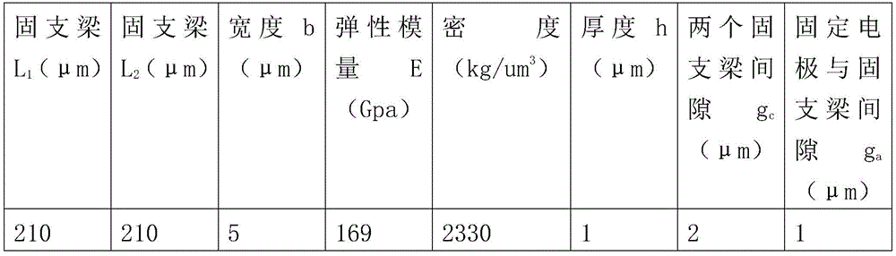
图2为全局驱动的基于模态局部化效应的传感器,图2中第三固支梁9第四固支梁10,两个固支梁之间的静电耦合作用面积为整个梁的表面积且整个第四固支梁10都受到固定电极的驱动,与图2所示的传感器相比本发明采用的局部驱动和局部静电进行耦合,这样能够在同样的驱动力下实现更高的激励幅值,因此具有更高的分辨率,图3为本发明在只有偏置电压作用下的特征值变化,按照本发明结构参数表1中的尺寸时,只有直流偏置电压作用下的特征值变化情况,横坐标为偏置电压(V),纵坐标为频率(KHz)。其中,ωi,j表示固有频率,i代表第i个固支梁,j表示第j阶固有频率。Fig. 2 is a globally driven sensor based on modal localization effect. In Fig. 2, the third clamped
表1微质量传感器结构参数Table 1 Structural parameters of micro-mass sensor
本发明基于高阶模态振动的微质量传感器结构是对称结构,因此,反对称模态(例如二阶模态)并不能被激起,而所提出的结构能够激发其在三阶模态附近振动。当在同样的激振力作用下,对比本发明所提局部驱动结构和基于模态局部化效应的传感器结果,图4为本发明的第一固支梁2与图2所示传感器的第三固支梁9在同样驱动力和耦合静电力下的幅频特性图比较图;The micro-mass sensor structure based on high-order modal vibration of the present invention is a symmetric structure, therefore, the anti-symmetric mode (eg, the second-order mode) cannot be excited, and the proposed structure can excite it to vibrate near the third-order mode. When under the same excitation force, comparing the results of the local drive structure proposed in the present invention and the sensor based on the modal localization effect, FIG. 4 shows the first clamped
图5为本发明的第二固支梁3与图2所述传感器的第四固支梁10在同样驱动力和耦合静电力下的幅频特性图比较图;FIG. 5 is a comparison diagram of the amplitude-frequency characteristics of the second clamped
在第一固支梁2和第二固支梁3上,局部驱动结构具有更大的幅值,这样能够提高传感器的分辨率;On the first clamped
通过在下耦合电极Ⅰ4-1、下耦合电极Ⅱ4-2,上耦合电极Ⅰ5-1,上耦合电极Ⅱ5-2之间施加耦合电压Vc=10V,在没有质量扰动时,先选择驱动电压源中交流电大小为Vac=0.02V,然后不断调节驱动电压源Ⅰ7中直流电Vdc使系统处于平衡状态,这里Vdc=1V,此时两固支梁的幅值相同。By applying a coupling voltage V c =10V between the lower coupling electrode I4-1, the lower coupling electrode II4-2, the upper coupling electrode I5-1 and the upper coupling electrode II5-2, when there is no mass disturbance, first select the driving voltage source in the The magnitude of the alternating current is V ac =0.02V, and then the direct current V dc in the driving voltage source I7 is continuously adjusted to keep the system in a balanced state, where V dc =1V, and the amplitudes of the two fixed beams are the same.
图6(a)为本发明在耦合电压为10V时,处于低阶模态振动下平衡状态下的幅频特性图;图7(a)为本发明在耦合电压为10V时,处于高阶模态振动下平衡状态下的幅频特性图,图6(a)和图7(a)分别是激发该系统在低阶模态和高阶模态振动下的幅频特性图。Figure 6(a) is the amplitude-frequency characteristic diagram of the present invention in a balanced state under low-order modal vibration when the coupling voltage is 10V; Figure 7(a) is the present invention in a high-order modal vibration when the coupling voltage is 10V Figure 6(a) and Figure 7(a) are the amplitude-frequency characteristic diagrams of the excitation system under low-order modal and high-order modal vibrations, respectively.
图6(b)为本发明在耦合电压为10V时,处于低阶模态振动下平衡状态下的相频特性图,图7(b)为本发明在耦合电压为10V时,处于高阶模态振动下平衡状态下的相频特性图,如图6(b)和图7(b)表示不论是在低阶模态还是高阶模态,该传感器的幅频特性都分别包括同相和异相模态,本发明分别对处于同相和异相振动下的灵敏度情况做了研究,Figure 6(b) is a phase-frequency characteristic diagram of the present invention in a balanced state under low-order modal vibration when the coupling voltage is 10V, and Figure 7(b) is a high-order modal vibration of the present invention when the coupling voltage is 10V Figure 6(b) and Figure 7(b) show the phase-frequency characteristics of the sensor in the low-order mode and the high-order mode. The amplitude-frequency characteristics of the sensor include in-phase and out-of-phase modes, respectively. In the present invention, the sensitivity conditions under in-phase and out-of-phase vibrations are respectively studied,
图8(a)为本发明在耦合电压为10V时,不同模态的幅值比在同相变化下的对比图;图8(b)为本发明在耦合电压为10V时,不同模态的幅值比在异相变化下的对比图;图8(c)为本发明在耦合电压为10V时,不同模态的频率在同相变化下的对比图;图8(d)为本发明在耦合电压为10V时,不同模态的频率在异相变化下的对比图,显示不论是低阶模态还是高阶模态下,当以相对幅值比作为灵敏度输出时其在异相振动下灵敏度更高。Figure 8(a) is a comparison diagram of the amplitude ratios of different modes under in-phase changes when the coupling voltage is 10V in the present invention; Figure 8(b) is the amplitude ratio of different modes when the coupling voltage is 10V in the present invention. The comparison diagram of the value ratio under the out-of-phase change; Fig. 8(c) is the comparison diagram of the frequency of different modes under the in-phase change when the coupling voltage is 10V of the present invention; Fig. 8(d) is the coupling voltage of the present invention. When it is 10V, the comparison diagram of the frequencies of different modes under out-of-phase changes shows that whether it is a low-order mode or a high-order mode, when the relative amplitude ratio is used as the sensitivity output, the sensitivity is higher under out-of-phase vibration.
由于频率是一种有单位(Hz)的量纲,而振幅比是无单位量纲,因此在比较频率灵敏度和振幅比灵敏度的时候,我们定义了相对灵敏度,相对频率变化和相对振幅比变化的灵敏度可以分别表示为:Since frequency is a unit (Hz) dimension, and amplitude ratio is a unitless dimension, when comparing frequency sensitivity and amplitude ratio sensitivity, we define relative sensitivity, relative frequency change and relative amplitude ratio change. The sensitivity can be expressed as:
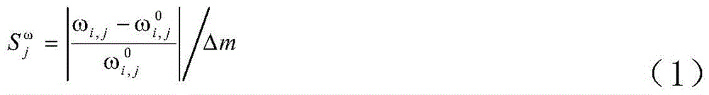
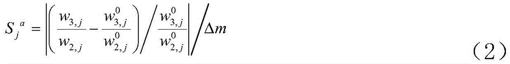
这里Sω和Sa分别表示基于谐振频率和振幅比的偏移的灵敏度,ω0 i,j是j阶模态下固支梁i在平衡状态的频率,ωi,j是j阶模态下固支梁i在添加质量后的频率,w2,j,w3,j是j阶模态添加质量后第一固支梁2和第二固支梁3的幅值变化,w2,j 0,w3,j 0分别是j阶模态平衡状态下的第一固支梁2和第二固支梁3的幅值。Here S ω and S a represent the sensitivity of the shift based on the resonant frequency and the amplitude ratio, respectively, ω 0 i,j is the frequency of the clamped beam i in the equilibrium state under the j-order mode, and ω i,j is the j-order mode The frequency of the lower clamped beam i after adding mass, w 2,j ,w 3,j is the amplitude change of the first clamped
鉴于图8(a)、图8(b)、图8(c)和图8(d),在第一固支梁2中间添加不同的扰动质量下不同固有频率下的频率相对变化和振幅比的相对变化情况,与传统的以频率相对变化作为灵敏度输出相比(因为以第一固支梁2和第二固支梁3的频率输出下灵敏度基本相等,所以图8中相对频率变化的输出结果是以第一固支梁2为对象),振幅比作为灵敏度输出方式可以大幅提高质量传感器的灵敏度,同样的质量扰动下,灵敏度可以提升3个数量级以上。而通过将传感器激发其在高阶模态振动能够得到超高的灵敏度,对比第二固支梁3的幅值比变化下的三阶模态振动与一阶模态振动下的灵敏度可知灵敏度提升15.23倍。表2为本发明实施方式中,通过调节耦合电极间的电压来实现传感器灵敏度的在线调整。当耦合电压等于15V时,输出幅值比39.07,当调节耦合电压为9V时,输出幅值比可达225.94,可以发现,仅仅通过改变耦合强度就能很方便的实现灵敏度大幅提高。In view of Fig. 8(a), Fig. 8(b), Fig. 8(c) and Fig. 8(d), the relative change of frequency and amplitude ratio at different natural frequencies with different disturbance masses added in the middle of the first clamped
表2高阶模态下不同耦合强度下幅值比相对变化Table 2 Relative changes of amplitude ratios under different coupling strengths in high-order modes
以上所述,仅为本发明较佳的具体实施方式,但本发明的保护范围并不局限于此,任何熟悉本技术领域的技术人员在本发明揭露的技术范围内,根据本发明的技术方案及其发明构思加以等同替换或改变,都应涵盖在本发明的保护范围之内。The above description is only a preferred embodiment of the present invention, but the protection scope of the present invention is not limited to this. The equivalent replacement or change of the inventive concept thereof shall be included within the protection scope of the present invention.
Claims (8)
Priority Applications (1)
| Application Number | Priority Date | Filing Date | Title |
|---|---|---|---|
| CN202010186923.6A CN111351553B (en) | 2020-03-17 | 2020-03-17 | A high-order modal micromass sensor based on modal localization effect |
Applications Claiming Priority (1)
| Application Number | Priority Date | Filing Date | Title |
|---|---|---|---|
| CN202010186923.6A CN111351553B (en) | 2020-03-17 | 2020-03-17 | A high-order modal micromass sensor based on modal localization effect |
Publications (2)
| Publication Number | Publication Date |
|---|---|
| CN111351553A true CN111351553A (en) | 2020-06-30 |
| CN111351553B CN111351553B (en) | 2021-08-03 |
Family
ID=71192820
Family Applications (1)
| Application Number | Title | Priority Date | Filing Date |
|---|---|---|---|
| CN202010186923.6A Active CN111351553B (en) | 2020-03-17 | 2020-03-17 | A high-order modal micromass sensor based on modal localization effect |
Country Status (1)
| Country | Link |
|---|---|
| CN (1) | CN111351553B (en) |
Cited By (3)
| Publication number | Priority date | Publication date | Assignee | Title |
|---|---|---|---|---|
| CN112595393A (en) * | 2020-12-11 | 2021-04-02 | 大连理工大学 | Modal localization micro-mass sensor with different-order modal coupling |
| CN112710865A (en) * | 2020-12-11 | 2021-04-27 | 大连理工大学 | Adjustable acceleration sensor based on modal localization effect |
| CN113092817A (en) * | 2021-03-03 | 2021-07-09 | 南京理工大学 | High-precision and wide-range acceleration sensor with switchable detection modes and control method thereof |
Citations (5)
| Publication number | Priority date | Publication date | Assignee | Title |
|---|---|---|---|---|
| US20090294638A1 (en) * | 2005-01-07 | 2009-12-03 | Trustees Of Boston University | Nanomechanical Oscillator |
| CN102269615A (en) * | 2011-05-07 | 2011-12-07 | 大连理工大学 | A micromass sensor based on a trough-shaped cantilever beam structure |
| CN102305658A (en) * | 2011-07-31 | 2012-01-04 | 大连理工大学 | An electrostatic adsorption micromass sensor |
| CN106645999A (en) * | 2016-09-20 | 2017-05-10 | 西北工业大学 | Micro-mechanical resonant electrometer with ultra-high sensitivity |
| CN110702555A (en) * | 2019-09-10 | 2020-01-17 | 大连理工大学 | A Tunable Micromass Sensor Based on Modal Localization Effect |
-
2020
- 2020-03-17 CN CN202010186923.6A patent/CN111351553B/en active Active
Patent Citations (5)
| Publication number | Priority date | Publication date | Assignee | Title |
|---|---|---|---|---|
| US20090294638A1 (en) * | 2005-01-07 | 2009-12-03 | Trustees Of Boston University | Nanomechanical Oscillator |
| CN102269615A (en) * | 2011-05-07 | 2011-12-07 | 大连理工大学 | A micromass sensor based on a trough-shaped cantilever beam structure |
| CN102305658A (en) * | 2011-07-31 | 2012-01-04 | 大连理工大学 | An electrostatic adsorption micromass sensor |
| CN106645999A (en) * | 2016-09-20 | 2017-05-10 | 西北工业大学 | Micro-mechanical resonant electrometer with ultra-high sensitivity |
| CN110702555A (en) * | 2019-09-10 | 2020-01-17 | 大连理工大学 | A Tunable Micromass Sensor Based on Modal Localization Effect |
Non-Patent Citations (3)
| Title |
|---|
| 徐伟华等: "失调耦合梁的模态局部化和频率轨迹转向现象", 《中山大学学报(自然科学版)》 * |
| 赵剑等: "双稳态屈曲梁的非线性跳跃特性研究", 《西安电子科技大学学报》 * |
| 赵剑等: "基于构型优化的高阶模态微质量传感器灵敏度提升方法", 《光学精密工程》 * |
Cited By (5)
| Publication number | Priority date | Publication date | Assignee | Title |
|---|---|---|---|---|
| CN112595393A (en) * | 2020-12-11 | 2021-04-02 | 大连理工大学 | Modal localization micro-mass sensor with different-order modal coupling |
| CN112710865A (en) * | 2020-12-11 | 2021-04-27 | 大连理工大学 | Adjustable acceleration sensor based on modal localization effect |
| CN112595393B (en) * | 2020-12-11 | 2021-09-17 | 大连理工大学 | Modal localization micro-mass sensor with different-order modal coupling |
| CN113092817A (en) * | 2021-03-03 | 2021-07-09 | 南京理工大学 | High-precision and wide-range acceleration sensor with switchable detection modes and control method thereof |
| CN113092817B (en) * | 2021-03-03 | 2023-04-07 | 南京理工大学 | High-precision and wide-range acceleration sensor with switchable detection modes and control method thereof |
Also Published As
| Publication number | Publication date |
|---|---|
| CN111351553B (en) | 2021-08-03 |
Similar Documents
| Publication | Publication Date | Title |
|---|---|---|
| CN110702555B (en) | Adjustable micro-mass sensor based on modal localization effect | |
| CN111351553A (en) | A high-order modal micromass sensor based on modal localization effect | |
| US6820469B1 (en) | Microfabricated teeter-totter resonator | |
| JP6313044B2 (en) | Mode-matching single proof mass 2-axis gyroscope and fabrication method | |
| Ide et al. | A low-profile design for the noncontact ultrasonically levitated stage | |
| CN107147370B (en) | A MEMS oscillator based on vibration mode coupling and its control method | |
| CN113098427B (en) | A Method of Phonon Frequency Comb Generation Based on MEMS Resonator Coupled Oscillators | |
| CN1898576A (en) | Combined magnetic field gradient and magnetic field strength sensor | |
| KR19980031896A (en) | Complementary electrostatic drive device of micro actuator | |
| CN103808961B (en) | Cantilever part and apply its resonant mode acceleration transducer | |
| CN104165624B (en) | Sidewall piezoelectric-driven ring vibrating gyroscope and driving and detection method | |
| CN109883602A (en) | A self-compensating silicon micro-resonant pressure-sensitive chip based on SOI | |
| WO2020062675A1 (en) | Acoustic micro-mass sensor and detection method | |
| Park et al. | Optimum design of circular CMUT membranes for high quality factor in air | |
| CN107515336A (en) | A low power consumption resonant electric field sensor | |
| Dougherty et al. | Detection of AC magnetic signals by parametric mode coupling in a mechanical oscillator | |
| CN112325998A (en) | Trace substance sensor and method based on internal resonance | |
| US6822929B1 (en) | Micro acoustic spectrum analyzer | |
| Carotenuto et al. | A new low voltage piezoelectric micromotor based on stator precessional motion | |
| CN112600528B (en) | Weak coupling resonator | |
| CN112595393B (en) | Modal localization micro-mass sensor with different-order modal coupling | |
| CN117169546B (en) | A differential acceleration sensor based on modal localization effect | |
| CN104897144A (en) | Multi-drive electrode mode-coupled micro-solid mode gyroscope | |
| CN102706924B (en) | Device for realizing second-order resonant excitation of micro-cantilever probe | |
| CN110631569A (en) | A MEMS single-ring ring vibrating gyro structure |
Legal Events
| Date | Code | Title | Description |
|---|---|---|---|
| PB01 | Publication | ||
| PB01 | Publication | ||
| SE01 | Entry into force of request for substantive examination | ||
| SE01 | Entry into force of request for substantive examination | ||
| GR01 | Patent grant | ||
| GR01 | Patent grant |