CN111325044A - Method for determining new component code of nuclear power station, identification system and identification method - Google Patents
Method for determining new component code of nuclear power station, identification system and identification method Download PDFInfo
- Publication number
- CN111325044A CN111325044A CN202010077640.8A CN202010077640A CN111325044A CN 111325044 A CN111325044 A CN 111325044A CN 202010077640 A CN202010077640 A CN 202010077640A CN 111325044 A CN111325044 A CN 111325044A
- Authority
- CN
- China
- Prior art keywords
- codes
- code
- identification
- expected
- new component
- Prior art date
- Legal status (The legal status is an assumption and is not a legal conclusion. Google has not performed a legal analysis and makes no representation as to the accuracy of the status listed.)
- Granted
Links
Images


Classifications
-
- G—PHYSICS
- G06—COMPUTING OR CALCULATING; COUNTING
- G06K—GRAPHICAL DATA READING; PRESENTATION OF DATA; RECORD CARRIERS; HANDLING RECORD CARRIERS
- G06K7/00—Methods or arrangements for sensing record carriers, e.g. for reading patterns
- G06K7/10—Methods or arrangements for sensing record carriers, e.g. for reading patterns by electromagnetic radiation, e.g. optical sensing; by corpuscular radiation
- G06K7/14—Methods or arrangements for sensing record carriers, e.g. for reading patterns by electromagnetic radiation, e.g. optical sensing; by corpuscular radiation using light without selection of wavelength, e.g. sensing reflected white light
- G06K7/1404—Methods for optical code recognition
- G06K7/1408—Methods for optical code recognition the method being specifically adapted for the type of code
- G06K7/1413—1D bar codes
-
- B—PERFORMING OPERATIONS; TRANSPORTING
- B41—PRINTING; LINING MACHINES; TYPEWRITERS; STAMPS
- B41J—TYPEWRITERS; SELECTIVE PRINTING MECHANISMS, i.e. MECHANISMS PRINTING OTHERWISE THAN FROM A FORME; CORRECTION OF TYPOGRAPHICAL ERRORS
- B41J2/00—Typewriters or selective printing mechanisms characterised by the printing or marking process for which they are designed
- B41J2/22—Typewriters or selective printing mechanisms characterised by the printing or marking process for which they are designed characterised by selective application of impact or pressure on a printing material or impression-transfer material
- B41J2/31—Typewriters or selective printing mechanisms characterised by the printing or marking process for which they are designed characterised by selective application of impact or pressure on a printing material or impression-transfer material using a print element with projections on its surface impacted or impressed by hammers
-
- B—PERFORMING OPERATIONS; TRANSPORTING
- B41—PRINTING; LINING MACHINES; TYPEWRITERS; STAMPS
- B41J—TYPEWRITERS; SELECTIVE PRINTING MECHANISMS, i.e. MECHANISMS PRINTING OTHERWISE THAN FROM A FORME; CORRECTION OF TYPOGRAPHICAL ERRORS
- B41J3/00—Typewriters or selective printing or marking mechanisms characterised by the purpose for which they are constructed
- B41J3/01—Typewriters or selective printing or marking mechanisms characterised by the purpose for which they are constructed for special character, e.g. for Chinese characters or barcodes
-
- G—PHYSICS
- G06—COMPUTING OR CALCULATING; COUNTING
- G06K—GRAPHICAL DATA READING; PRESENTATION OF DATA; RECORD CARRIERS; HANDLING RECORD CARRIERS
- G06K7/00—Methods or arrangements for sensing record carriers, e.g. for reading patterns
- G06K7/10—Methods or arrangements for sensing record carriers, e.g. for reading patterns by electromagnetic radiation, e.g. optical sensing; by corpuscular radiation
- G06K7/14—Methods or arrangements for sensing record carriers, e.g. for reading patterns by electromagnetic radiation, e.g. optical sensing; by corpuscular radiation using light without selection of wavelength, e.g. sensing reflected white light
- G06K7/1404—Methods for optical code recognition
- G06K7/1408—Methods for optical code recognition the method being specifically adapted for the type of code
- G06K7/1417—2D bar codes
Landscapes
- Physics & Mathematics (AREA)
- Engineering & Computer Science (AREA)
- Health & Medical Sciences (AREA)
- Electromagnetism (AREA)
- General Health & Medical Sciences (AREA)
- Toxicology (AREA)
- Artificial Intelligence (AREA)
- Computer Vision & Pattern Recognition (AREA)
- General Physics & Mathematics (AREA)
- Theoretical Computer Science (AREA)
- Monitoring And Testing Of Nuclear Reactors (AREA)
Abstract
Description
技术领域technical field
本发明的实施例涉及核工程技术领域,特别涉及一种用于核电站新组件编码的确定方法、识别系统及识别方法。Embodiments of the present invention relate to the technical field of nuclear engineering, and in particular, to a determination method, an identification system and an identification method for coding of new components of a nuclear power plant.
背景技术Background technique
核反应堆中各类组件是维持链式反应和反应堆功率控制的重要元件,所有组件均有唯一的编号,组件的转移及操作十分重要。为了保证组件操作的正确性,有必要对组件编号进行识别。Various components in a nuclear reactor are important components to maintain the chain reaction and reactor power control. All components have unique numbers, and the transfer and operation of components are very important. In order to ensure the correct operation of the component, it is necessary to identify the component number.
然而,现有的压水堆和快堆等领域,对于组件的插拔操作以及运输过程,均未设置任何识别装置来对组件编号进行自动判断,由此极有可能因为人因失误而导致组件插拔错误和运输错误,从而造成损失甚至引发危险。However, in the fields of existing pressurized water reactors and fast reactors, there is no identification device to automatically determine the component number for the plugging and unplugging operations of components and the transportation process. Incorrect insertion and removal and transport errors, resulting in damage and even danger.
采用明码标记的组件编号不具有纠错功能,识读率低,一位数字被挡住或污损,整个编号就无法识别,不适用于核电站组件编号的自动读取。因此必须对核电站组件编号的标记方法进行改造创新,提高其纠错能力、识读率和抗污损能力。当前已实现组件编号编码化,并标记在组件某一位置处,通过编码识别设备识别组件编码。The component number marked with clear code has no error correction function, and the reading rate is low. If one digit is blocked or defaced, the entire number cannot be recognized, and it is not suitable for automatic reading of the component number of nuclear power plants. Therefore, it is necessary to transform and innovate the marking method of nuclear power plant component numbers to improve its error correction ability, reading rate and anti-fouling ability. At present, the component number has been coded and marked at a certain position of the component, and the component code is identified by the code identification device.
发明内容SUMMARY OF THE INVENTION
本发明的主要目的在于提供一种用于核电站新组件编码的确定方法、识别系统及识别方法,以解决上述技术问题中的至少一个方面。The main purpose of the present invention is to provide a determination method, an identification system and an identification method for coding of new components of a nuclear power plant, so as to solve at least one aspect of the above technical problems.
根据本发明的一个方面,提出了一种用于核电站新组件编码的确定方法,包括:针对由A种尺寸和B种深度值共同限定的A×B种编码,将其设于核电站新组件上,并利用识别装置对其进行识别试验,以确定编码的A1种期望尺寸和B1种期望深度值;针对A1×B1种编码,利用具有多种安装角度的识别装置对每一种编码进行识别试验,以确定识别装置的期望安装角度;将所述识别装置以所述期望安装角度安装,并进行以下步骤:针对A1×B1种编码,以编码相对于所述识别装置的视野中心的偏移角度为变量进行识别试验,以确定编码的A2种期望尺寸和B2种期望深度值;针对A2×B2种编码,以所述偏移角度为变量,利用所述识别装置通过导向管的第一开孔对编码进行识别试验,以确定编码的A3种期望尺寸和B3种期望深度值;以及针对A3×B3种编码,以编码的移动速度为变量进行识别试验,以确定编码的最优期望尺寸和最优期望深度值。According to one aspect of the present invention, a method for determining a code for a new component of a nuclear power plant is proposed, which includes: setting A×B codes on the new components of a nuclear power plant for A×B codes jointly defined by A size and B depth values , and use the identification device to carry out the identification test to determine the A1 expected size and B1 expected depth value of the code; for the A1×B1 encoding, use the identification device with various installation angles to carry out the identification test for each code , to determine the desired installation angle of the identification device; install the identification device at the desired installation angle, and perform the following steps: for A1×B1 kinds of coding, to encode the offset angle relative to the center of the visual field of the identification device Carry out identification tests for variables to determine the A2 desired sizes and B2 desired depth values of the codes; for A2×B2 codes, use the identification device to pass through the first opening of the guide tube with the offset angle as a variable Carry out identification tests on the encoding to determine the A3 desired sizes and B3 desired depth values of the encoding; and for A3×B3 encodings, perform identification tests with the moving speed of the encoding as a variable to determine the optimal expected size and the most optimal encoding. The optimal expected depth value.
根据一些实施方式,对所述A×B种编码进行识别试验包括:将所述A×B种编码设于控制棒组件上并进行识别试验,以确定编码的a1种期望尺寸和b1种期望深度值;以及针对a1×b1种编码,将其设于燃料棒组件上并进行识别试验,以确定编码的A1种期望尺寸和B1种期望深度值。According to some embodiments, performing the identification test on the A×B codes includes: setting the A×B codes on the control rod assembly and performing the identification test to determine a1 desired sizes and b1 desired depths of the codes value; and for a1×b1 kinds of codes, set it on the fuel rod assembly and carry out identification tests to determine the A1 kinds of expected size and B1 kinds of depth values of the codes.
根据一些实施方式,对所述A1×B1种编码进行识别试验包括:将所述A1×B1种编码设于控制棒组件上,并在多个所述偏移角度下进行识别试验,以确定编码的a2种期望尺寸和b2种期望深度值;以及将a2×b2种编码设于燃料棒组件上,并在多个所述偏移角度下进行识别试验,以确定编码的A2种期望尺寸和B2种期望深度值。According to some embodiments, performing an identification test on the A1×B1 kinds of codes includes: setting the A1×B1 kinds of codes on the control rod assembly, and performing an identification test under a plurality of the offset angles to determine the codes a2 desired sizes and b2 desired depths of a desired depth value.
根据一些实施方式,所述方法还包括:对所述A2×B2种编码进行识别试验包括:将所述A2×B2种编码设于控制棒组件上,利用所述识别装置通过导向管的第一开孔对编码进行识别试验,以确定编码的a3种期望尺寸和b3种期望深度值;以及将a3×b3种编码设于燃料棒组件上,利用所述识别装置通过导向管的第一开孔对编码进行识别试验,以确定编码的A3种期望尺寸和B3种期望深度值。According to some embodiments, the method further includes: performing an identification test on the A2×B2 kinds of codes includes: setting the A2×B2 kinds of codes on the control rod assembly, and using the identification device to pass the first part of the guide tube Carry out the identification test for the code through the opening to determine the a3 expected sizes and b3 expected depth values of the code; and set the a3×b3 codes on the fuel rod assembly, and use the identification device to pass through the first opening of the guide tube Identification trials are performed on the encoding to determine A3 expected sizes and B3 expected depth values for the encoding.
根据一些实施方式,所述方法还包括:对所述A3×B3种编码进行识别试验包括:将所述A3×B3种编码设于控制棒组件上,并将所述控制棒组件设置为以多个速度移动,利用所述识别装置对编码进行识别,以确定编码的a4种期望尺寸和b4种期望深度值;以及将a4×b4种编码设于燃料棒组件上,并将所述燃料棒组件设置为以多个速度移动,利用所述识别装置对编码进行识别,以确定编码的最优期望尺寸和最优期望深度值。According to some embodiments, the method further includes: performing an identification test on the A3×B3 kinds of codes includes: setting the A3×B3 kinds of codes on a control rod assembly, and setting the control rod assembly to have multiple moving at a speed, using the identifying device to identify the codes to determine the a4 expected sizes and b4 expected depth values of the codes; and setting the a4×b4 codes on the fuel rod assemblies, and placing the fuel rod assemblies on the fuel rod assemblies Arranged to move at a plurality of speeds, the encoding is identified by the identification means to determine an optimal desired size and an optimal desired depth value of the encoding.
根据一些实施方式,基于编码的识别时间和识别率来判断编码的识别效果。According to some embodiments, the recognition effect of the coding is judged based on the recognition time and recognition rate of the coding.
根据一些实施方式,所述A种尺寸不超过新组件在编码标记位置处的直径的16%;以及所述B种深度值的范围为不超过500μm。According to some embodiments, the A dimension is no more than 16% of the diameter of the new component at the location of the coding mark; and the B depth value is in a range of no more than 500 μm.
根据一些实施方式,编码采用针式打标装置形成。According to some embodiments, the code is formed using a pin marking device.
根据本发明的另一方面,提出了一种用于核电站新组件编码的识别系统,包括:针式打标装置,设置为在新组件的头部形成期望编码,所述期望编码具有根据所述的编码确定方法确定的所述最优期望深度值和所述最优期望尺寸;新组件装载机,设置为对形成有期望编码的新组件进行转移,所述新组件装载机包括导向管和导向柱,新组件设于导向管内,并与导向管一同相对于导向柱移动,所述导向管具有第一开孔,所述导向柱具有第二开孔;以及安装于所述第二开孔内的识别装置和偏振光源,所述偏振光源能够通过第一开孔照射新组件的期望编码,所述识别装置能够通过第一开孔对期望编码进行识别;其中,所述第二开孔具有倾角,使得识别装置具有所述的编码确定方法确定的所述期望安装角度。According to another aspect of the present invention, an identification system for coding of a new component of a nuclear power plant is proposed, comprising: a pin marking device, configured to form a desired coding on the head of the new component, the desired coding having the code according to the the optimal desired depth value and the optimal desired size determined by the coding determination method; a new component loader, configured to transfer the new component formed with the desired coding, the new component loader comprising a guide tube and a guide The new assembly is arranged in a guide tube and moves relative to the guide column together with the guide tube, the guide tube has a first opening, the guide column has a second opening; and is installed in the second opening The identification device and the polarized light source are provided, the polarized light source can illuminate the desired code of the new component through the first opening, and the identification device can identify the desired code through the first opening; wherein, the second opening has an inclination angle , so that the identification device has the desired installation angle determined by the code determination method.
根据一些实施方式,所述第一开孔的位置根据所述第二开孔的位置以及所述新组件装载机的导向管位置确定。According to some embodiments, the position of the first opening is determined according to the position of the second opening and the position of the guide tube of the new component loader.
根据一些实施方式,所述新组件的头部包括由多个槽分隔开的多个圆弧面,所述多个圆弧面上均设有所述期望编码。According to some embodiments, the head of the new assembly includes a plurality of arcuate surfaces separated by a plurality of slots, each of which is provided with the desired code.
根据本发明的另一方面,提出了一种利用所述的识别系统对新组件编码进行识别的方法,包括:利用针式打标装置在新组件的头部形成期望编码;以及利用新组件装载机对形成有期望编码的新组件进行转移;其中,在新组件装载机对新组件进行转移的过程中,利用偏振光源照射所述期望编码,并且利用识别装置对期望编码进行识别,以对正在操作的新组件进行确认。According to another aspect of the present invention, a method for identifying a new component code by using the identification system is proposed, which includes: forming a desired code on the head of the new component by using a pin marking device; and using the new component to load The machine transfers the new component formed with the desired code; wherein, in the process of transferring the new component by the new component loader, the desired code is irradiated with a polarized light source, and the desired code is identified by the identification device, so as to identify the desired code. The new component of the operation is confirmed.
在根据本发明的实施例的用于核电站新组件编码的确定方法中,通过确定编码的最优期望深度值、最优期望尺寸以及识别装置的期望安装角度,以及设置偏振光源,可以保证识别装置对处于新组件装载机的黑暗环境中且运动的编码具有良好识别效果,由此在新组件的运输过程中,能够同时对正在操作的新组件进行自动识别,从而在不影响现有工艺过程的情况下,能够更全面、可靠地掌握组件信息,提高组件操作的可靠性。In the method for determining coding for a new component of a nuclear power plant according to an embodiment of the present invention, by determining the optimal desired depth value, optimal desired size of coding, and desired installation angle of the identification device, and setting the polarized light source, the identification device can be guaranteed It has a good recognition effect on the code of movement in the dark environment of the new component loader, so that during the transportation of the new component, the new component in operation can be automatically recognized at the same time, so that it does not affect the existing process. In this case, the component information can be grasped more comprehensively and reliably, and the reliability of the component operation can be improved.
附图说明Description of drawings
通过下文中参照附图对本发明所作的描述,本发明的其它目的和优点将显而易见,并可帮助对本发明有全面的理解。Other objects and advantages of the present invention will be apparent from the following description of the present invention with reference to the accompanying drawings, and may assist in a comprehensive understanding of the present invention.
图1示出了根据本发明的一个示例性实施例的新组件的结构示意图;Figure 1 shows a schematic structural diagram of a new component according to an exemplary embodiment of the present invention;
图2示出了图1的新组件的头部的示意图;Figure 2 shows a schematic diagram of the head of the new assembly of Figure 1;
图3示出了根据本发明的一个示例性实施例的新组件的编码的示意图;Figure 3 shows a schematic diagram of the encoding of a new component according to an exemplary embodiment of the present invention;
图4示出了根据本发明的一个示例性实施例的识别装置的安装角度的示意图;FIG. 4 shows a schematic diagram of the installation angle of the identification device according to an exemplary embodiment of the present invention;
图5示出了根据本发明的一个示例性实施例的用于核电站新组件编码的确定方法的流程图;FIG. 5 shows a flow chart of a method for determining a code for a new component of a nuclear power plant according to an exemplary embodiment of the present invention;
图6示出了根据本发明的一个示例性实施例的新组件装载机的结构示意图。FIG. 6 shows a schematic structural diagram of a new component loader according to an exemplary embodiment of the present invention.
具体实施方式Detailed ways
下面通过实施例,并结合附图,对本发明的技术方案作进一步具体的说明。在说明书中,相同或相似的附图标号指示相同或相似的部件。The technical solutions of the present invention will be further described in detail below through embodiments and in conjunction with the accompanying drawings. In the specification, the same or similar reference numerals refer to the same or similar parts.
在下面的详细描述中,为便于解释,阐述了许多具体的细节以提供对本披露实施例的全面理解。然而明显地,一个或多个实施例在没有这些具体细节的情况下也可以被实施。在其他情况下,公知的结构和装置以图示的方式体现以简化附图。In the following detailed description, for convenience of explanation, numerous specific details are set forth in order to provide a thorough understanding of the disclosed embodiments. Obviously, however, one or more embodiments may be practiced without these specific details. In other instances, well-known structures and devices are shown in diagram form in order to simplify the drawings.
核电站组件包括新组件和乏组件,其中,进入核反应堆之前的组件称为新组件,从核反应堆出来的组件称为乏组件。核电站组件的种类例如可以包括燃料棒组件、控制棒组件等。图1示出了根据本发明的一个示例性实施例的新组件10的结构示意图,图2示出了图1的新组件10的头部11的示意图。如图1-2所示,以燃料棒组件为例,新组件10包括头部11、燃料段12以及管脚段13。新组件10整体呈圆柱状,头部11包括由多个槽分隔开的多个圆弧面。参照图2,在头部11的圆柱面上开有六个槽,六个槽等分圆柱面,形成六个圆弧面。每个槽对应一个冷却剂出口孔。The components of a nuclear power plant include new components and spent components. The components before entering the nuclear reactor are called new components, and the components coming out of the nuclear reactor are called spent components. Types of nuclear power plant assemblies may include, for example, fuel rod assemblies, control rod assemblies, and the like. FIG. 1 shows a schematic structural diagram of a
在核反应堆中,新组件10的种类和数量繁多,每个新组件10上均设有唯一的编号。在本发明的实施例中,通过自动识别技术来识别并核对进入反应堆的新组件是否正确。明码标记的编号为八位数字编号,其不具有纠错功能,识读率低,一位数字被挡住或污损,整个编号就无法识别,不适用于核电站组件编号的自动读取,因此需要将现有的编号标记转换为编码标记,以提高编码的读取率和可靠性。编码包括一维编码和二维编码,两者均具有纠错功能。具体地,二维编码包括DM码和QR码。本发明对一维编码和二维编码(DM码和QR码)的数据类型、数据数量、安全可靠性、识读率、纠错能力等进行了比较分析,结果如表1所示。In a nuclear reactor, there are many kinds and quantities of
表1一维编码、二维编码(DM码和QR码)分析比较Table 1 Analysis and comparison of one-dimensional code and two-dimensional code (DM code and QR code)

根据以上比较,以上编码方式均满足8位数字编码的要求;二维编码相较于一维编码,具有信息量大、安全可靠、识读率高、纠错能力强等优点。对于DM码和QR码,两者都有很强的纠错能力,但DM码在编码破损的表现更为出色,有些条码只需读取资料的20%即可精确辨读;同时,DM码的尺寸可任意调整,最大可到14平方英寸,最小可到0.0002平方英寸,这个尺寸也是目前一维编码与二维编码中最小的。因此,本发明的编码形式优选采用DM码。进一步地,本发明选用的DM码类型为ECC200。ECC200利用Reed-Solomon算法产生多项式计算错误纠正码,是性能优良的纠错码,它具有纠正突发错误和随机错误的能力,而纠正突发错误更为有效,在线性分组码中它的纠错能力和编码效率是最高的。According to the above comparison, the above encoding methods all meet the requirements of 8-bit digital encoding; compared with one-dimensional encoding, two-dimensional encoding has the advantages of large amount of information, safety and reliability, high reading rate, and strong error correction ability. For DM code and QR code, both have strong error correction ability, but DM code has better performance in code damage, some barcodes can be accurately read only by reading 20% of the data; meanwhile, DM code The size can be adjusted arbitrarily, the maximum can be 14 square inches, the minimum can be 0.0002 square inches, this size is also the smallest one-dimensional encoding and two-dimensional encoding. Therefore, the coding form of the present invention preferably adopts the DM code. Further, the DM code type selected by the present invention is ECC200. ECC200 uses the Reed-Solomon algorithm to generate polynomial error correction codes. It is an error correction code with excellent performance. It has the ability to correct burst errors and random errors, and it is more effective to correct burst errors. Error capability and coding efficiency are the highest.
新组件的外表面材料一般为不锈钢,外形为圆柱面,应用于辐射环境中。新组件外表面的材料、形状和应用环境三者对在新组件上形成编码的方式做出了限制和要求。现有的加工永久性标记的方法一般采用直接零件标记技术DPM(Direct Part Marking),是将可机器识读的编码直接标记在产品或零件表面上的技术。DPM技术可以分为:The outer surface material of the new components is generally stainless steel, and the shape is a cylindrical surface, which is used in the radiation environment. The material, shape, and application environment of the outer surface of the new component impose constraints and requirements on the way codes can be formed on the new component. The existing method of processing permanent marks generally adopts the direct part marking technology DPM (Direct Part Marking), which is a technology of directly marking machine-readable codes on the surface of a product or part. DPM technology can be divided into:
激光直接标记技术(Laser Marking),激光与材料相互作用,材料热影响区温度短时间内迅速上升,使被加工材料表面产生熔化、烧蚀甚至汽化等,从而形成标记;Laser direct marking technology (Laser Marking), the laser interacts with the material, and the temperature of the material heat affected zone rises rapidly in a short period of time, causing the surface of the processed material to melt, ablate or even vaporize, thereby forming a mark;
电化学刻蚀技术(Electro-Chemical Etching),利用电子/化学反应,将预先设计和打印的模板印在材料上;Electro-Chemical Etching, which uses electronic/chemical reactions to print pre-designed and printed templates on materials;
喷墨标记技术(Ink Jet Marking),DPM的喷墨打印机与常见的PC打印机原理相同,它可以精确地将墨滴喷射到材料表面;Ink Jet Marking, DPM's ink jet printer works on the same principle as common PC printers, it can accurately eject ink droplets onto the surface of the material;
机械点针标记技术(Dot Peen),利用碳化物或金刚石笔尖以气动或机电方式打击材料表面,形成永久凹痕,目前二维编码的打标工艺为电磁点针打标。Mechanical Dot Peen marking technology (Dot Peen) uses carbide or diamond nibs to strike the surface of the material in a pneumatic or electromechanical manner to form permanent dents. The current two-dimensional coding marking process is electromagnetic Dot Peen marking.
本发明对四种DPM标记技术进行对比分析,结果如表2所示。The present invention compares and analyzes four DPM labeling technologies, and the results are shown in Table 2.
表2 DPM标记技术分析Table 2 Analysis of DPM labeling technology
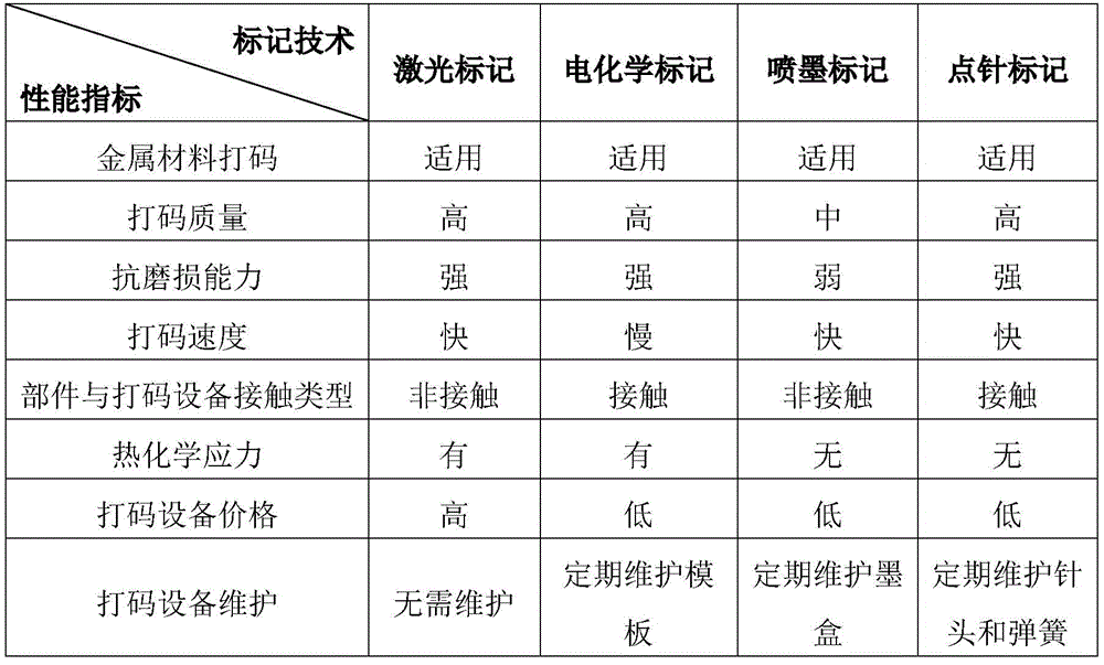
根据以上分析,以上四种标记技术均能满足在金属材质上打码,但电化学标记打码速度较慢,且与金属产生化学反应,不适于用作新组件的标记技术;喷墨标记抗磨损能力弱,也不适于用作新组件的标记技术。According to the above analysis, the above four marking technologies can all meet the requirements of coding on metal materials, but the speed of electrochemical marking is slow, and the chemical reaction with metal occurs, which is not suitable for marking technology for new components; inkjet marking is resistant to It has poor wear resistance and is not suitable for use as a marking technique for new components.
本发明对激光标记技术和点针标记技术的标记效果分别进行试验,发现使用激光标记技术达到100μm以上的编码深度时存在标记时间过长(约300s)以及工件熔融、编码质量差的问题;而使用点针标记技术得到的编码清晰、标记时间短。此外,组件要在堆芯冷却剂里长时间浸泡,冷却剂的高温和强腐蚀性会对编码进行加热并会导致发生化学腐蚀反应。本发明模拟堆芯的高温和强腐蚀性环境对组件编码进行浸泡试验,将点针标记和激光标记的两种试验样品放在模拟的高温和强腐蚀性液体中持续加热240小时,取出并清洗后,发现点针标记的样品仅表面变乌、失去金属光泽;而激光标记的样品不仅表面变乌、失去金属光泽,而且编码对比度差、边缘区域已磨损、黑色区域被还原腐蚀,即激光标记会在金属表面形成不稳定的氧化物,金属氧化物在高温强腐蚀性液体中很快被还原,从而给堆芯冷却剂带来氧与金属杂质的污染,影响堆芯冷却剂的纯净度。The invention tests the marking effects of the laser marking technology and the dot needle marking technology respectively, and finds that when the laser marking technology is used to reach a coding depth of more than 100 μm, there are problems that the marking time is too long (about 300s), the workpiece is melted, and the coding quality is poor; The code obtained using the dot-pin marking technology is clear and the marking time is short. In addition, the components are immersed in the core coolant for a long time, and the high temperature and strong corrosiveness of the coolant will heat the code and cause a chemical corrosion reaction. The invention simulates the high temperature and strong corrosive environment of the core to carry out the immersion test on the component code, and puts the two test samples marked with the dot needle and the laser mark in the simulated high temperature and strong corrosive liquid for continuous heating for 240 hours, and then takes them out and cleans them. Afterwards, it was found that the surface of the sample marked with the dot needle only turned black and lost its metallic luster; while the laser-marked sample not only turned black and lost its metallic luster, but also had poor coding contrast, worn edge areas, and reduced black areas, that is, laser marking. Unstable oxides will be formed on the metal surface, and the metal oxides will be quickly reduced in high temperature and strong corrosive liquids, which will contaminate the core coolant with oxygen and metal impurities and affect the purity of the core coolant.
可见,针刻标记的二维编码比激光标记的二维编码的耐腐蚀性能更好,读取率也相应更高,本发明采用针刻标记方式,即采用针式打标装置形成编码。图3示出了根据本发明的一个示例性实施例的新组件的编码21的示意图,如图3所示,编码21的图案由针式打标装置点针打标形成的多个点构成。It can be seen that the two-dimensional code marked by needle engraving has better corrosion resistance and higher reading rate than the two-dimensional code marked by laser marking. FIG. 3 shows a schematic diagram of the
新组件编码21的识别效果取决于编码的尺寸以及深度,编码太深且尺寸太小,导致编码太密集,不易识别;编码太浅且尺寸太大,导致编码太稀疏,也不易识别。同时,新组件标记编码的位置为圆柱面,编码标记尺寸越大,受到弧面弯曲的影响越大,编码越不易被识别;但编码尺寸越小,在相同污染程度下,编码部分被污染的比例就越大,影响后续的识别效果。The recognition effect of the
此外,识别装置的识别角度也会对识别效果产生影响,当识别装置的镜头以一定角度面对编码而非正对编码时,可以加强编码与新组件表面之间的对比度,从而达到良好的识别效果。图4示出了根据本发明的一个示例性实施例的识别装置41的安装角度的示意图,如图4所示,识别装置41相对于水平方向成角度α安装,安装角度决定了识别装置41的识别角度,识别装置41的镜头正对方向与水平方向之间也成角度α。In addition, the recognition angle of the recognition device will also affect the recognition effect. When the lens of the recognition device faces the code at a certain angle instead of directly facing the code, the contrast between the code and the surface of the new component can be enhanced to achieve good recognition. Effect. 4 shows a schematic diagram of the installation angle of the
可见,新组件编码尺寸、编码深度值以及识别装置的安装角度是决定编码识别效果的关键,本发明提出了一种选择合适的编码尺寸、编码深度值以及识别装置安装角度的方法。It can be seen that the coding size, coding depth value and the installation angle of the recognition device of the new component are the keys to determine the coding recognition effect.
图5示出了根据本发明的一个示例性实施例的用于核电站新组件编码的确定方法的流程图,如图5所示,所述方法可以包括:Fig. 5 shows a flowchart of a method for determining a code for a new component of a nuclear power plant according to an exemplary embodiment of the present invention. As shown in Fig. 5, the method may include:
S1,针对由A种尺寸和B种深度值共同限定的A×B种编码,将其设于核电站新组件上,并利用识别装置对其进行识别试验,以确定编码的A1种期望尺寸和B1种期望深度值;S1, for the A×B codes jointly defined by the A size and the B depth value, set it on the new component of the nuclear power plant, and use the identification device to carry out the identification test to determine the desired size of the code A1 and B1 a desired depth value;
S2,针对A1×B1种编码,利用具有多种安装角度的识别装置对每一种编码进行识别试验,以确定识别装置的期望安装角度;S2, for A1×B1 kinds of codes, use identification devices with multiple installation angles to perform identification tests on each code to determine the expected installation angle of the identification device;
将所述识别装置以所述期望安装角度安装,并进行以下步骤:Install the identification device at the desired installation angle and perform the following steps:
S3,针对A1×B1种编码,以编码相对于所述识别装置的视野中心的偏移角度为变量进行识别试验,以确定编码的A2种期望尺寸和B2种期望深度值;S3, for A1×B1 kinds of codes, carry out the identification test with the offset angle of the code relative to the center of the visual field of the identification device as a variable, so as to determine the A2 kinds of expected sizes and B2 kinds of expected depth values of the encoding;
S4,针对A2×B2种编码,以所述偏移角度为变量,利用所述识别装置通过导向管的第一开孔对编码进行识别试验,以确定编码的A3种期望尺寸和B3种期望深度值;以及S4, for A2×B2 kinds of codes, using the offset angle as a variable, use the identification device to perform an identification test on the codes through the first opening of the guide tube, so as to determine the A3 kinds of desired sizes and B3 kinds of desired depths of the codes value; and
S5,针对A3×B3种编码,以编码的移动速度为变量进行识别试验,以确定编码的最优期望尺寸和最优期望深度值。S5 , for A3×B3 kinds of encodings, the identification test is carried out with the moving speed of the encoding as a variable, so as to determine the optimal expected size and the optimal expected depth value of the encoding.
在根据本发明的实施例的新组件编码的确定方法中,通过确定编码的最优期望深度值、最优期望尺寸以及识别装置的期望安装角度,可以保证识别装置对处于运动状态的编码具有良好识别效果,由此在新组件的运输过程中,能够同时对正在操作的新组件进行自动识别,从而在不影响现有工艺过程的情况下,能够更全面、可靠地掌握组件信息,提高组件操作的可靠性。In the method for determining the encoding of the new component according to the embodiment of the present invention, by determining the optimal expected depth value, the optimal expected size of the encoding, and the expected installation angle of the identification device, it can be ensured that the identification device has a good performance for the encoding in the moving state. Recognition effect, so that during the transportation of new components, the new components in operation can be automatically recognized at the same time, so that the component information can be grasped more comprehensively and reliably without affecting the existing process, and the operation of the components can be improved. reliability.
以上各步骤中,可以基于编码的识别时间和识别率来判断编码的识别效果,即利用识别装置对各编码进行识别,识别时间越短表明识别效果越好,识别率越高表明识别效果越好,对识别效果好的编码对应的尺寸、深度值以及安装角度进行选择。所述A种尺寸不超过新组件在编码标记位置处的直径的16%,即编码宽度不超过新组件在编码标记位置处的直径的16%;所述B种深度值的范围为不超过500μm。各编码均为利用针式打标装置形成的DM码。In the above steps, the recognition effect of the coding can be judged based on the recognition time and recognition rate of the coding, that is, the recognition device is used to recognize each code. The shorter the recognition time is, the better the recognition effect is, and the higher the recognition rate is, the better the recognition effect is. , select the size, depth value and installation angle corresponding to the code with good recognition effect. The size of type A does not exceed 16% of the diameter of the new component at the position of the coding mark, that is, the width of the coding does not exceed 16% of the diameter of the new component at the position of the coding mark; the range of the depth value of type B is not more than 500μm . Each code is a DM code formed by a needle marking device.
经过步骤S1,可以根据A种尺寸的编码的识别效果缩小编码尺寸的范围,在该范围内再确定A1种期望尺寸,同时可以根据B种深度值的编码的识别效果缩小编码深度值的范围,在该范围内再确定B1种期望深度值,之后再进行步骤S2的识别试验。After step S1, the range of the coding size can be reduced according to the recognition effect of the coding of the A size, and the desired size of A1 can be determined within the range, and the range of the coded depth value can be reduced according to the recognition effect of the coding of the B depth value, Within this range, B1 kinds of expected depth values are determined again, and then the identification test of step S2 is performed.
具体地,步骤S1中,对所述A×B种编码进行识别试验可包括:Specifically, in step S1, performing an identification test on the A×B codes may include:
将所述A×B种编码设于控制棒组件上并进行识别试验,以确定编码的a1种期望尺寸和b1种期望深度值;以及disposing the AxB codes on the control rod assembly and performing an identification test to determine a1 desired sizes and b1 desired depth values of the codes; and
针对a1×b1种编码,将其设于燃料棒组件上并进行识别试验,以确定编码的A1种期望尺寸和B1种期望深度值。For the a1×b1 kinds of codes, set them on the fuel rod assembly and carry out identification tests to determine the A1 kinds of expected sizes and B1 kinds of expected depth values of the codes.
由于控制棒组件在编码标记位置处的外径小于燃料棒组件在编码标记位置处的外径,那么针对相同尺寸的编码,控制棒组件上的编码受曲面曲率的影响偏大,即相同尺寸的编码在控制棒组件上比在燃料棒组件上变形更为严重、更不易识别,因此可以先在控制棒组件上进行试验,根据A种尺寸的试验结果确定第一尺寸范围,并在该范围内确定a1种期望尺寸;类似地,可以确定出第一深度值范围,并在该范围内确定b1种期望深度值;然后将a1种期望尺寸和b1种深度值共同限定的a1×b1种编码设于燃料棒组件上进行识别试验,根据a1种期望尺寸和b1种深度值的试验结果确定第二尺寸范围和第二深度值范围,并从中确定步骤S2的A1种期望尺寸和B1种期望深度值。在步骤S1中,识别装置的安装角度、编码相对于识别装置的视野中心的偏移角度以及组件的移动速度均为确定值,并且不设置导向管。Since the outer diameter of the control rod assembly at the position of the coding mark is smaller than the outer diameter of the fuel rod assembly at the position of the coding mark, for the coding of the same size, the coding on the control rod assembly is more affected by the curvature of the curved surface, that is, the coding of the same size The deformation of the code on the control rod assembly is more serious and difficult to identify than that on the fuel rod assembly, so the test can be carried out on the control rod assembly first, and the first size range is determined according to the test results of size A, and within this range Determine a1 kinds of expected sizes; similarly, a first depth value range can be determined, and b1 kinds of expected depth values are determined within this range; Carry out the identification test on the fuel rod assembly, determine the second size range and the second depth value range according to the test results of the a1 desired sizes and the b1 depth values, and determine the A1 desired sizes and the B1 desired depth values in step S2. . In step S1, the installation angle of the identification device, the offset angle of the code relative to the center of the field of view of the identification device, and the moving speed of the assembly are all determined values, and no guide tube is provided.
在步骤S2中,编码相对于识别装置的视野中心的偏移角度以及组件的移动速度均为确定值,并且不设置导向管。In step S2, the offset angle of the code relative to the center of the visual field of the identification device and the moving speed of the assembly are both determined values, and no guide tube is provided.
步骤S3中,对所述A1×B1种编码进行识别试验包括:In step S3, the identification test for the A1×B1 codes includes:
将所述A1×B1种编码设于控制棒组件上,并在多个所述偏移角度下进行识别试验,以确定编码的a2种期望尺寸和b2种期望深度值;以及Setting the A1×B1 codes on the control rod assembly, and performing identification tests at a plurality of the offset angles to determine a2 desired sizes and b2 desired depth values of the codes; and
将a2×b2种编码设于燃料棒组件上,并在多个所述偏移角度下进行识别试验,以确定编码的A2种期望尺寸和B2种期望深度值。A2×b2 kinds of codes are set on the fuel rod assembly, and identification tests are carried out at a plurality of the offset angles to determine the A2 kinds of desired sizes and B2 kinds of desired depth values of the codes.
在步骤S3中,识别装置的安装角度以及组件的移动速度均为确定值,并且不设置导向管。In step S3, the installation angle of the identification device and the moving speed of the assembly are both determined values, and no guide tube is provided.
具体地,识别装置以所述期望安装角度安装,将每一种编码设置为相对于所述识别装置的视野中心具有多个偏移角度,并在所述多个偏移角度下对每一种编码进行识别。对所得到的不同的读码时间进行数据分析及处理,并对成功读码次数进行统计,得到各编码在不同的偏移角度下的平均识别时间和识别率,根据识别时间最短和识别率最高的原则,选取所述期望尺寸。Specifically, the identification device is installed at the desired installation angle, each code is set to have a plurality of offset angles with respect to the center of the field of view of the identification device, and each code is set at the plurality of offset angles. code for identification. Perform data analysis and processing on the obtained different code reading times, and count the number of successful code readings to obtain the average recognition time and recognition rate of each code at different offset angles. According to the shortest recognition time and the highest recognition rate principle, select the desired size.
当编码的一部分进入识别装置的视野范围内时也有可能被识别出,因此加入偏移角度进行综合考量,可以保证选取结果更加合理。When a part of the code enters the field of view of the identification device, it may also be identified. Therefore, adding the offset angle for comprehensive consideration can ensure that the selection result is more reasonable.
对于新组件,其运输过程包括利用新组件装载机进行转移,新组件装载机是新组件工艺运输的主要设备,其功能是抓取和插入新组件。图6示出了根据本发明的一个示例性实施例的新组件装载机30的结构示意图,如图6所示,新组件装载机30包括导向柱32以及设于导向柱32内的导向管31,由钢丝绳控制的抓取装置抓取和插入新组件,新组件在导向管31内并与导向管31一起沿竖直方向上下运动,导向柱32固定在机械设备上,并能以一定的弧度水平旋转运动。本发明在新组件装载机转移新组件的过程中对编码进行识别,因此需要在导向柱32上设置第二开孔34用于安装识别装置,相应地,在导向管31上设置第一开孔33使得新组件的编码暴露于识别装置的视野之中,避免导向管管壁的阻挡。For new components, the transportation process includes transfer using new component loader, which is the main equipment for new component process transportation, and its function is to grab and insert new components. FIG. 6 shows a schematic structural diagram of a
步骤S4中,对所述A2×B2种编码进行识别试验包括:In step S4, the identification test for the A2×B2 kinds of codes includes:
将所述A2×B2种编码设于控制棒组件上,利用所述识别装置通过导向管的第一开孔对编码进行识别试验,以确定编码的a3种期望尺寸和b3种期望深度值;以及The A2×B2 kinds of codes are set on the control rod assembly, and the identification test is performed on the codes through the first opening of the guide tube by the identification device, so as to determine a3 kinds of desired sizes and b3 kinds of desired depth values of the codes; and
将a3×b3种编码设于燃料棒组件上,利用所述识别装置通过导向管的第一开孔对编码进行识别试验,以确定编码的A3种期望尺寸和B3种期望深度值。Set the a3×b3 codes on the fuel rod assembly, and use the identification device to perform an identification test on the codes through the first opening of the guide tube to determine the A3 desired sizes and B3 desired depth values of the codes.
其中,识别装置以所述期望安装角度安装,编码设置为相对于所述识别装置的视野中心具有多个偏移角度,在所述多个偏移角度下通过所述第一开孔对所述期望编码进行识别。统计识别装置能否成功读取以及计算读取时间,基于识别时间和识别率来进一步确定编码的A3种期望尺寸和B3种期望深度值。Wherein, the identification device is installed at the desired installation angle, the code is set to have a plurality of offset angles relative to the center of the field of view of the identification device, and the first opening is used for the identification of the identification device at the plurality of offset angles. Expect encoding for identification. Count whether the recognition device can successfully read and calculate the reading time, and further determine the A3 expected sizes and B3 expected depth values of the encoding based on the recognition time and recognition rate.
在步骤S4中,识别装置的安装角度以及组件的移动速度均为确定值。In step S4, the installation angle of the identification device and the moving speed of the assembly are both determined values.
步骤S5中,对所述A3×B3种编码进行识别试验包括:In step S5, the identification test for the A3×B3 codes includes:
将所述A3×B3种编码设于控制棒组件上,并将所述控制棒组件设置为以多个速度移动,利用所述识别装置对编码进行识别,以确定编码的a4种期望尺寸和b4种期望深度值;以及The A3×B3 codes are set on the control rod assembly, and the control rod assembly is set to move at multiple speeds, and the codes are identified by the identification device to determine the a4 desired sizes of the codes and b4 a desired depth value; and
将a4×b4种编码设于燃料棒组件上,并将所述燃料棒组件设置为以多个速度移动,利用所述识别装置对编码进行识别,以确定编码的最优期望尺寸和最优期望深度值。A4×b4 kinds of codes are set on the fuel rod assemblies, and the fuel rod assemblies are set to move at a plurality of speeds, and the codes are identified by the identification device, so as to determine the optimal desired size and optimal expectation of the codes depth value.
在步骤S5中,识别装置的安装角度、编码相对于识别装置的视野中心的偏移角度均为确定值,并且不设置导向管。In step S5, the installation angle of the identification device and the offset angle of the code relative to the center of the field of view of the identification device are all determined values, and no guide tube is provided.
加入运动状态的考量,可以保证确定的编码适用于真实环境。Including the consideration of the motion state, it can be ensured that the determined encoding is suitable for the real environment.
至此,根据以上方法,可以确定合适的编码尺寸、编码深度值以及识别装置的安装角度。So far, according to the above method, the appropriate encoding size, encoding depth value and installation angle of the identification device can be determined.
根据本发明的另一方面,提出了一种用于核电站新组件编码的识别系统,包括:According to another aspect of the present invention, an identification system for coding new components of a nuclear power plant is proposed, comprising:
针式打标装置,设置为在新组件的头部形成期望编码,所述期望编码具有根据以上编码确定方法确定的所述最优期望深度值和所述最优期望尺寸;a pin marking device, configured to form a desired code at the head of the new component, the desired code having the optimal desired depth value and the optimal desired size determined according to the above code determination method;
新组件装载机30,设置为对形成有期望编码的新组件进行转移,新组件装载机30包括导向管31和导向柱32,新组件设于导向管31内,并与导向管31一同相对于导向柱32移动,导向管31具有第一开孔33,导向柱32具有第二开孔34;以及The
安装于第二开孔34内的识别装置和偏振光源,所述偏振光源能够通过第一开孔33照射新组件的期望编码,所述识别装置能够通过第一开孔33对期望编码进行识别;an identification device and a polarized light source installed in the
其中,第二开孔34具有倾角,使得识别装置具有根据以上编码确定方法确定的所述期望安装角度。Wherein, the
识别装置沿第二开孔34安装,识别装置的期望安装角度与第二开孔的倾角角度相同。第二开孔34可以贯穿导向柱一侧的侧壁。为识别装置配置偏振光源,能够在导向柱的黑暗环境中为编码的识别提供照明。第一开孔33的位置根据第二开孔34的位置以及新组件装载机30的导向管位置确定,使得当新组件的编码进入识别装置的视野范围时,第一开孔33可以将新组件编码暴露出来。The identification device is installed along the
本发明将期望编码设置在新组件的头部,由于新组件在新组件装载机30内运动时,新组件的头部最先暴露在识别装置的视野范围内,因此可最先对新组件编码进行识别,识别装置将识别结果发送至监控单元,与监控单元存储的预设信息进行比较,以判断抓取的新组件是否正确;并且,新组件装载机采用钢丝绳驱动抓取装置带着新组件在导向管内上下移动,钢丝绳连接是一种柔性连接,这使得组件会偏离轴线左右晃动,而组件头部比组件管脚段的晃动幅度要小,将编码设于头部更有利于编码的稳定识别;此外,新组件头部的辐照剂量最小,对识别装置的辐照损伤最小。In the present invention, the desired code is set on the head of the new assembly. Since the head of the new assembly is first exposed in the visual field of the identification device when the new assembly moves in the
考虑到识别装置的安装位置是固定的,而新组件上的期望编码的位置相对于识别装置的方位不确定,为了增加新组件编码识别的冗余度和可靠性,本发明在新组件的头部的多个圆弧面上均设有所述期望编码。Considering that the installation position of the identification device is fixed, and the position of the desired code on the new assembly is uncertain relative to the orientation of the identification device, in order to increase the redundancy and reliability of the identification of the new assembly code, the present invention is in the head of the new assembly. The desired codes are provided on a plurality of arc surfaces of the part.
根据本发明的另一方面,提出了一种利用所述的识别系统对新组件编码进行识别的方法,包括:According to another aspect of the present invention, a method for identifying new component codes by using the identification system is proposed, comprising:
利用针式打标装置在新组件的头部形成期望编码;以及Utilize a pin marking device to form the desired code on the head of the new assembly; and
利用新组件装载机对形成有期望编码的新组件进行转移;Using a new component loader to transfer new components formed with the desired code;
其中,在新组件装载机对新组件进行转移的过程中,利用偏振光源照射所述期望编码,并且利用识别装置对期望编码进行识别,以对正在操作的新组件进行确认。Wherein, in the process of transferring the new assembly by the new assembly loader, the desired code is irradiated with a polarized light source, and the desired code is identified by an identification device, so as to confirm the new assembly being operated.
在一些实施方式中,对新组件编码进行识别的方法可以包括:In some embodiments, the method of identifying the new component code may include:
利用针式打标装置在新组件的头部形成期望编码;Use a pin marking device to form the desired code on the head of the new component;
根据编码标记区域的尺寸计算识别装置的视野范围,并根据经验公式计算出识别装置的图像分辨率,从而选择某种规格的识别装置;根据识别装置与新组件编码的距离(物距)以及视野范围,计算出识别装置的镜头的焦距,从而选择合适的镜头;并根据识别装置的视野范围确定导向管的第一开孔的大小;以及Calculate the field of view of the recognition device according to the size of the coding mark area, and calculate the image resolution of the recognition device according to the empirical formula, so as to select a certain specification of recognition device; The focal length of the lens of the identification device is calculated to select a suitable lens; and the size of the first opening of the guide tube is determined according to the field of view of the identification device; and
利用新组件装载机对形成有期望编码的新组件进行转移;Using a new component loader to transfer new components formed with the desired code;
其中,在新组件装载机对新组件进行转移的过程中,利用偏振光源照射所述期望编码,并且利用识别装置对期望编码进行识别,以对正在操作的新组件进行确认。Wherein, in the process of transferring the new assembly by the new assembly loader, the desired code is irradiated with a polarized light source, and the desired code is identified by an identification device, so as to confirm the new assembly being operated.
本发明还可以通过中子辐照试验对识别装置进行辐照试验,判断识别装置能可靠工作的时间,包括:模拟新组件装载机从新组件运输容器中抓取新组件时识别装置所处的环境;计算出识别装置在一定的时间内所承受的总的中子注量,并留有余量;从识别装置实际承受辐照的各类中子辐照中选择一种单能量中子;让识别装置被所述单能量中子不间断照射,使其达到所述总的中子注量。在此试验过程中,识别装置在不停的进行编码识别试验,监视编码识别时间,判断识别装置在中子辐照过程中是否失效,如果一直没有失效,则识别装置能可靠地在上述时间内工作;如果在某一时刻失效,则识别装置只能可靠地在那一时刻之前的时间内可靠地工作。The present invention can also conduct an irradiation test on the identification device through a neutron irradiation test to determine the time when the identification device can work reliably, including: simulating the environment where the identification device is located when a new component loader grabs a new component from a new component transport container ; Calculate the total neutron flux that the identification device is subjected to within a certain period of time, and leave a margin; select a single-energy neutron from the various types of neutron irradiation that the identification device actually bears; let The identification device is continuously irradiated with said single-energy neutrons to achieve said total neutron fluence. During this test process, the identification device is constantly performing code identification tests, monitoring the code identification time, and judging whether the identification device fails during the neutron irradiation process. work; if it fails at a certain time, the identification device can only work reliably for the time before that time.
虽然结合附图对本发明进行了说明,但是附图中公开的实施例旨在对本发明的实施方式进行示例性说明,而不能理解为对本发明的一种限制。为了清楚地示出各个部件的细节,附图中的各个部件并不是按比例绘制的,所以附图中的各个部件的比例也不应作为一种限制。Although the present invention has been described with reference to the accompanying drawings, the embodiments disclosed in the accompanying drawings are intended to illustrate the embodiments of the present invention and should not be construed as a limitation of the present invention. In order to clearly show the details of the various components, the various components in the drawings are not drawn to scale and therefore the proportions of the various components in the drawings should not be taken as a limitation.
虽然本发明总体构思的一些实施例已被显示和说明,本领域普通技术人员将理解,在不背离本发明总体构思的原则和精神的情况下,可对这些实施例做出改变,本发明的范围以权利要求和它们的等同物限定。Although some embodiments of the present general inventive concept have been shown and described, those of ordinary skill in the art will appreciate that changes may be made to these embodiments without departing from the principles and spirit of the present general inventive concept. The scope is defined by the claims and their equivalents.
Claims (12)
Priority Applications (1)
| Application Number | Priority Date | Filing Date | Title |
|---|---|---|---|
| CN202010077640.8A CN111325044B (en) | 2020-01-31 | 2020-01-31 | Determination method, identification system and identification method for new component code of nuclear power plant |
Applications Claiming Priority (1)
| Application Number | Priority Date | Filing Date | Title |
|---|---|---|---|
| CN202010077640.8A CN111325044B (en) | 2020-01-31 | 2020-01-31 | Determination method, identification system and identification method for new component code of nuclear power plant |
Publications (2)
| Publication Number | Publication Date |
|---|---|
| CN111325044A true CN111325044A (en) | 2020-06-23 |
| CN111325044B CN111325044B (en) | 2021-08-20 |
Family
ID=71172965
Family Applications (1)
| Application Number | Title | Priority Date | Filing Date |
|---|---|---|---|
| CN202010077640.8A Active CN111325044B (en) | 2020-01-31 | 2020-01-31 | Determination method, identification system and identification method for new component code of nuclear power plant |
Country Status (1)
| Country | Link |
|---|---|
| CN (1) | CN111325044B (en) |
Citations (11)
| Publication number | Priority date | Publication date | Assignee | Title |
|---|---|---|---|---|
| US5811779A (en) * | 1996-08-22 | 1998-09-22 | General Electric Company | Laser bar code reader system for a fuel rod in a boiling water nuclear reactor |
| US20020153423A1 (en) * | 2001-04-18 | 2002-10-24 | Schramm Harry F. | Multiple layer identification label using stacked identification symbols |
| CN1981291A (en) * | 2004-06-30 | 2007-06-13 | 通明国际科技有限公司 | Laser-based method and system for processing targeted surface material and article produced thereby |
| CN102360570A (en) * | 2011-09-01 | 2012-02-22 | 中科华核电技术研究院有限公司 | Telescoping guide tube and light-water reactor nuclear power station fuel assembly |
| CN102893608A (en) * | 2010-04-13 | 2013-01-23 | 弗兰霍菲尔运输应用研究公司 | Coding of Spatial Sampling of Two-Dimensional Information Signals Using Subdivision |
| CN102892544A (en) * | 2010-05-07 | 2013-01-23 | 林肯环球股份有限公司 | Welding system and method using arc welding machines and laser beam source |
| CN103428527A (en) * | 2013-08-08 | 2013-12-04 | 北京宽客网络技术有限公司 | Real-time data source media stream transformation method and breakpoint switching play method |
| US20170131090A1 (en) * | 2015-11-06 | 2017-05-11 | Intel Corporation | Systems, methods, and apparatuses for implementing maximum likelihood image binarization in a coded light range camera |
| CN107108114A (en) * | 2014-12-11 | 2017-08-29 | Qbo咖啡有限责任公司 | Drink capsule, beverage preparation system and drink capsule recognition methods |
| CN108573295A (en) * | 2018-04-17 | 2018-09-25 | 湖南镭目科技有限公司 | A tracking method and tracking device for a spent fuel assembly |
| CN108665989A (en) * | 2018-05-10 | 2018-10-16 | 中广核核电运营有限公司 | Nuclear Power Station's Exhausted Fuels associated component shears capacity reduction method |
-
2020
- 2020-01-31 CN CN202010077640.8A patent/CN111325044B/en active Active
Patent Citations (11)
| Publication number | Priority date | Publication date | Assignee | Title |
|---|---|---|---|---|
| US5811779A (en) * | 1996-08-22 | 1998-09-22 | General Electric Company | Laser bar code reader system for a fuel rod in a boiling water nuclear reactor |
| US20020153423A1 (en) * | 2001-04-18 | 2002-10-24 | Schramm Harry F. | Multiple layer identification label using stacked identification symbols |
| CN1981291A (en) * | 2004-06-30 | 2007-06-13 | 通明国际科技有限公司 | Laser-based method and system for processing targeted surface material and article produced thereby |
| CN102893608A (en) * | 2010-04-13 | 2013-01-23 | 弗兰霍菲尔运输应用研究公司 | Coding of Spatial Sampling of Two-Dimensional Information Signals Using Subdivision |
| CN102892544A (en) * | 2010-05-07 | 2013-01-23 | 林肯环球股份有限公司 | Welding system and method using arc welding machines and laser beam source |
| CN102360570A (en) * | 2011-09-01 | 2012-02-22 | 中科华核电技术研究院有限公司 | Telescoping guide tube and light-water reactor nuclear power station fuel assembly |
| CN103428527A (en) * | 2013-08-08 | 2013-12-04 | 北京宽客网络技术有限公司 | Real-time data source media stream transformation method and breakpoint switching play method |
| CN107108114A (en) * | 2014-12-11 | 2017-08-29 | Qbo咖啡有限责任公司 | Drink capsule, beverage preparation system and drink capsule recognition methods |
| US20170131090A1 (en) * | 2015-11-06 | 2017-05-11 | Intel Corporation | Systems, methods, and apparatuses for implementing maximum likelihood image binarization in a coded light range camera |
| CN108573295A (en) * | 2018-04-17 | 2018-09-25 | 湖南镭目科技有限公司 | A tracking method and tracking device for a spent fuel assembly |
| CN108665989A (en) * | 2018-05-10 | 2018-10-16 | 中广核核电运营有限公司 | Nuclear Power Station's Exhausted Fuels associated component shears capacity reduction method |
Non-Patent Citations (2)
| Title |
|---|
| P. VASKA等: "A compact scintillator-based coded aperture imager for localizing illicit nuclear materials", 《2007 IEEE NUCLEAR SCIENCE SYMPOSIUM CONFERENCE RECORD》 * |
| 苏艾玲: "核燃料组件商品归类探讨", 《物流工程与管理》 * |
Also Published As
| Publication number | Publication date |
|---|---|
| CN111325044B (en) | 2021-08-20 |
Similar Documents
| Publication | Publication Date | Title |
|---|---|---|
| US6533181B1 (en) | Direct marking of parts with encoded symbology method, apparatus and symbolody | |
| US20050218126A1 (en) | Method and a device for depositing a wipe-proof and rub-proof marking onto transparent glass | |
| US9033220B2 (en) | Production management method for steel tubes and pipes | |
| JP4570389B2 (en) | Method for forming two-dimensional code by laser marking and laser marking apparatus | |
| CA2612634A1 (en) | Marking and reading system | |
| EP2390045A3 (en) | Method and apparatus for laser marking an object | |
| KR860001436B1 (en) | Pattern Identification Apparatus and Method | |
| EP3399468B1 (en) | Method for quantitative defacing of a qr code | |
| CN113330368A (en) | System and method for permanent marking of flexographic printing plates and printing plates marked therewith | |
| CN111325044A (en) | Method for determining new component code of nuclear power station, identification system and identification method | |
| US20090017271A1 (en) | Densely packed sensor arrays | |
| EP4042245A1 (en) | System and process for persistent marking of flexo plates and plates marked therewith | |
| US9707785B2 (en) | System and method for analysis of compact printed test patterns | |
| WO2006088991A2 (en) | Apparatus and method for controlling a programmable marking scribe | |
| CN111259852A (en) | Identification system and identification method for nuclear power station component codes | |
| CN102806776B (en) | Method for printing two-dimensional bar code on multi-copy bill by stylus printer | |
| CN1336583A (en) | Matrix code printing and identifying method | |
| Jangsombatsiri et al. | Artificial neural network approach to data matrix laser direct part marking | |
| CN215041466U (en) | Four-degree-of-freedom printing device | |
| CN1590112A (en) | Printer and label | |
| CN102806788B (en) | A kind of method printing special-shaped matrix two-dimensional barcode on multiple part bills | |
| CN211015526U (en) | A full life cycle logistics tracking device of carbon anode for aluminum | |
| Jangsombatsiri et al. | Enhancing Traceability with Laser-based Direct Part Marking | |
| CN223131656U (en) | Mechanism for trace-back code micro-nano light gathering and printing | |
| RU2249265C2 (en) | Method for identifying spent fuel assembly |
Legal Events
| Date | Code | Title | Description |
|---|---|---|---|
| PB01 | Publication | ||
| PB01 | Publication | ||
| SE01 | Entry into force of request for substantive examination | ||
| SE01 | Entry into force of request for substantive examination | ||
| GR01 | Patent grant | ||
| GR01 | Patent grant |