CN111308530B - Short wave multi-station and single-satellite cooperative direct positioning method based on two-dimensional direction of arrival - Google Patents
Short wave multi-station and single-satellite cooperative direct positioning method based on two-dimensional direction of arrival Download PDFInfo
- Publication number
- CN111308530B CN111308530B CN202010095378.XA CN202010095378A CN111308530B CN 111308530 B CN111308530 B CN 111308530B CN 202010095378 A CN202010095378 A CN 202010095378A CN 111308530 B CN111308530 B CN 111308530B
- Authority
- CN
- China
- Prior art keywords
- satellite
- radiation source
- short
- station
- array
- Prior art date
- Legal status (The legal status is an assumption and is not a legal conclusion. Google has not performed a legal analysis and makes no representation as to the accuracy of the status listed.)
- Active
Links
- 238000000034 method Methods 0.000 title claims abstract description 58
- 230000005855 radiation Effects 0.000 claims abstract description 86
- 239000013598 vector Substances 0.000 claims abstract description 49
- 238000005457 optimization Methods 0.000 claims abstract description 32
- 230000014509 gene expression Effects 0.000 claims abstract description 20
- 238000012545 processing Methods 0.000 claims abstract description 11
- 239000011159 matrix material Substances 0.000 claims description 26
- 230000009467 reduction Effects 0.000 claims description 15
- 238000005070 sampling Methods 0.000 claims description 9
- 239000000654 additive Substances 0.000 claims description 4
- 230000000996 additive effect Effects 0.000 claims description 4
- 238000007476 Maximum Likelihood Methods 0.000 claims description 3
- 239000005433 ionosphere Substances 0.000 claims description 3
- 230000009466 transformation Effects 0.000 claims 1
- 238000005516 engineering process Methods 0.000 description 6
- 238000010586 diagram Methods 0.000 description 5
- 238000006243 chemical reaction Methods 0.000 description 2
- 238000004891 communication Methods 0.000 description 2
- 238000000342 Monte Carlo simulation Methods 0.000 description 1
- 238000004458 analytical method Methods 0.000 description 1
- 230000009286 beneficial effect Effects 0.000 description 1
- 230000005540 biological transmission Effects 0.000 description 1
- 230000008859 change Effects 0.000 description 1
- 230000006866 deterioration Effects 0.000 description 1
- 230000000694 effects Effects 0.000 description 1
- 238000002474 experimental method Methods 0.000 description 1
- 238000009776 industrial production Methods 0.000 description 1
- 230000004807 localization Effects 0.000 description 1
- 238000012986 modification Methods 0.000 description 1
- 230000004048 modification Effects 0.000 description 1
- 238000012544 monitoring process Methods 0.000 description 1
- 238000011160 research Methods 0.000 description 1
Images


Classifications
-
- G—PHYSICS
- G01—MEASURING; TESTING
- G01S—RADIO DIRECTION-FINDING; RADIO NAVIGATION; DETERMINING DISTANCE OR VELOCITY BY USE OF RADIO WAVES; LOCATING OR PRESENCE-DETECTING BY USE OF THE REFLECTION OR RERADIATION OF RADIO WAVES; ANALOGOUS ARRANGEMENTS USING OTHER WAVES
- G01S19/00—Satellite radio beacon positioning systems; Determining position, velocity or attitude using signals transmitted by such systems
- G01S19/38—Determining a navigation solution using signals transmitted by a satellite radio beacon positioning system
- G01S19/39—Determining a navigation solution using signals transmitted by a satellite radio beacon positioning system the satellite radio beacon positioning system transmitting time-stamped messages, e.g. GPS [Global Positioning System], GLONASS [Global Orbiting Navigation Satellite System] or GALILEO
- G01S19/42—Determining position
- G01S19/45—Determining position by combining measurements of signals from the satellite radio beacon positioning system with a supplementary measurement
- G01S19/46—Determining position by combining measurements of signals from the satellite radio beacon positioning system with a supplementary measurement the supplementary measurement being of a radio-wave signal type
Landscapes
- Engineering & Computer Science (AREA)
- Radar, Positioning & Navigation (AREA)
- Remote Sensing (AREA)
- Computer Networks & Wireless Communication (AREA)
- Physics & Mathematics (AREA)
- General Physics & Mathematics (AREA)
- Position Fixing By Use Of Radio Waves (AREA)
Abstract
本发明公开一种基于二维波达方向的短波多站和单星协同直接定位方法,对能够同时发射短波信号和卫星信号的待定位辐射源,依次建立该辐射源地理坐标与发射的短波信号到达不同短波观测站的方位角和仰角的代数关系式;确定短波观测站中的阵列流形向量关于地理坐标的导数表达式;建立该辐射源地理坐标与发射的卫星信号到达单颗卫星的方位角和仰角的代数关系式;确定单颗卫星中的阵列流形向量关于地理坐标的导数表达式;将采集的阵列信号数据传输至地面中心站进行处理,基于短波信号数据和卫星信号数据获得估计辐射源经纬度的优化模型,并进行数值优化,获得辐射源经纬度的估计值。本发明能够显著提升对地球表面远距离辐射源的定位精度。

The invention discloses a short-wave multi-station and single-satellite cooperative direct positioning method based on the two-dimensional direction of arrival. For a radiation source to be located that can simultaneously transmit short-wave signals and satellite signals, the geographic coordinates of the radiation source and the transmitted short-wave signals are sequentially established. The algebraic relationship between the azimuth and elevation angles arriving at different short-wave observation stations; determine the derivative expression of the array manifold vector in the short-wave observation station with respect to the geographic coordinates; establish the geographic coordinates of the radiation source and the azimuth of the transmitted satellite signal arriving at a single satellite Algebraic relationship between angle and elevation angle; determine the derivative expression of the array manifold vector in a single satellite with respect to geographic coordinates; transmit the collected array signal data to the ground central station for processing, and obtain estimates based on shortwave signal data and satellite signal data The optimization model of the longitude and latitude of the radiation source is carried out numerical optimization to obtain the estimated value of the longitude and latitude of the radiation source. The invention can significantly improve the positioning accuracy of the long-distance radiation source on the earth's surface.
Description
技术领域technical field
本发明属于无线信号定位技术领域,尤其涉及一种基于二维波达方向的短波多站和单星协同直接定位方法。The invention belongs to the technical field of wireless signal positioning, and in particular relates to a short-wave multi-station and single-satellite coordinated direct positioning method based on two-dimensional direction of arrival.
背景技术Background technique
众所周知,无线信号定位技术广泛应用于通信、雷达、目标监测、导航遥测、地震勘测、射电天文、紧急救助、安全管理等领域,其在工业生产和军事应用中都发挥着重要作用。As we all know, wireless signal positioning technology is widely used in communication, radar, target monitoring, navigation telemetry, seismic survey, radio astronomy, emergency rescue, safety management and other fields, and it plays an important role in industrial production and military applications.
对目标进行定位(即位置参数估计)可以使用雷达、激光、声纳等有源设备来完成,该类技术称为有源定位技术,它具有全天候、高精度等优点。然而,有源定位系统通常需要依靠发射大功率电磁信号来实现,因此极易暴露自己的位置,容易被对方发现,从而遭到对方电子干扰的影响,导致定位性能急剧恶化,甚至会危及系统自身的安全性和可靠性。The positioning of the target (that is, the position parameter estimation) can be completed by using active equipment such as radar, laser, and sonar. This type of technology is called active positioning technology, which has the advantages of all-weather and high precision. However, active positioning systems usually rely on transmitting high-power electromagnetic signals to achieve, so it is easy to expose their own position, easy to be discovered by the other party, and thus affected by the other party's electronic interference, resulting in a sharp deterioration of positioning performance, and even endanger the system itself security and reliability.
目标定位还可以利用目标(主动)辐射或者(被动)散射的无线电信号来实现,该类技术称为无源定位技术,它是指在观测站(也称传感器)在不主动发射电磁信号的情况下,通过接收目标辐射或者散射的无线电信号来估计目标的位置参数。与有源定位系统相比,无源定位系统具有不主动发射电磁信号、生存能力强、侦察作用距离远等优势,从而得到国内外学者的广泛关注和深入研究。Target positioning can also be achieved by using target (active) radiation or (passive) scattered radio signals. This type of technology is called passive positioning technology, which refers to the situation where the observation station (also called the sensor) does not actively emit electromagnetic signals. Next, the position parameters of the target are estimated by receiving radio signals radiated or scattered by the target. Compared with active positioning systems, passive positioning systems have the advantages of not actively transmitting electromagnetic signals, strong survivability, and long-distance reconnaissance, which have attracted extensive attention and in-depth research by scholars at home and abroad.
现有的辐射源定位体制大都是基于单手段进行的,例如短波手段、超短波手段以及卫星手段等等。每一种定位手段都能适用于一定的频段范围,并且具有特定的优势。然而,每一种定位手段也都有其缺点,在特定的场景下存在一些弊端,例如短波手段往往在辐射源纬度方向上的定位误差较大,而卫星手段往往在辐射源经度方向上的定位误差较大。现有的定位体制很少将不同的定位手段进行协同处理,即多手段协同定位。要实现多手段协同定位,需要待定位辐射源能够同时发射不同频段的信号,在实际场景中这是有可能实现的,例如一艘舰船可能会同时发射短波信号和卫星信号。Most of the existing radiation source positioning systems are based on single means, such as short-wave means, ultra-short-wave means and satellite means. Each positioning method is applicable to a certain frequency range and has specific advantages. However, each positioning method also has its own shortcomings. There are some disadvantages in certain scenarios. For example, shortwave methods often have large positioning errors in the latitude direction of the radiation source, while satellite methods often locate in the longitude direction of the radiation source. The error is large. The existing positioning systems rarely co-process different positioning means, that is, multi-means co-location. To achieve multi-method co-location, the radiation source to be located needs to be able to transmit signals in different frequency bands at the same time. This is possible in practical scenarios. For example, a ship may transmit short-wave signals and satellite signals at the same time.
另一方面,传统无源定位技术大多采用两步估计方式,即首先从接收信号中提取出用于定位的相关参数(主要包括空域、时域、频域以及能量域等参量),然后利用这些中间参数确定目标位置参数或者速度参数。虽然这种两步定位模式在现代无源定位系统中被广泛使用,但以色列学者A.J.Weiss和A.Amar(Amar A,Weiss A J.Localization ofnarrowband radio emitters based on Doppler frequency shifts[J].IEEETransactions on Signal Processing,2008,56(11):5500-5508.)(Weiss A J.Directgeolocation of wideband emitters based on delay and Doppler[J].IEEETransactions on Signal Processing,2011,59(6):2513-5520.)却指出了其中所存在的诸多缺点,并提出了直接定位的思想,其基本理念是从信号采集的数据域中直接估计目标的位置参数,而无需估计其它中间定位参数。显然,这种直接定位体制同样适用于多手段协同定位中。On the other hand, most of the traditional passive positioning technology adopts a two-step estimation method, that is, firstly extract the relevant parameters for positioning from the received signal (mainly including parameters such as spatial domain, time domain, frequency domain and energy domain), and then use these parameters. The intermediate parameter determines the target position parameter or the speed parameter. Although this two-step positioning mode is widely used in modern passive positioning systems, Israeli scholars A.J.Weiss and A.Amar (Amar A,Weiss A J.Localization ofnarrowband radio emitters based on Doppler frequency shifts[J].IEEETransactions on Signal Processing,2008,56(11):5500-5508.)(Weiss A J.Directgeolocation of wideband emitters based on delay and Doppler[J].IEEETransactions on Signal Processing,2011,59(6):2513-5520.) However, it pointed out many shortcomings, and proposed the idea of direct positioning. Obviously, this direct positioning system is also applicable to multi-means co-location.
基于上述分析,本专利针对能够同时发射短波信号和卫星信号的待定位辐射源,提出了一种基于二维波达方向的短波多站和单星协同直接定位方法,可以显著提升对地球表面远距离辐射源的定位精度。Based on the above analysis, this patent proposes a short-wave multi-station and single-satellite coordinated direct positioning method based on two-dimensional direction of arrival for radiation sources to be located that can simultaneously transmit short-wave signals and satellite signals, which can significantly improve the distance to the earth's surface. The positioning accuracy of the distance radiation source.
发明内容SUMMARY OF THE INVENTION
本发明针对现有的定位体制很少将不同的定位手段进行协同处理且对地球表面远距离辐射源的定位精度较低的问题,针对能够同时发射短波信号和卫星信号的待定位辐射源,提出一种基于二维波达方向的短波多站和单星协同直接定位方法,可以显著提升对地球表面远距离辐射源的定位精度。Aiming at the problems that the existing positioning systems rarely perform coordinated processing of different positioning means and the positioning accuracy of long-distance radiation sources on the earth's surface is low, the present invention proposes a radiation source to be positioned that can simultaneously transmit short-wave signals and satellite signals. A short-wave multi-station and single-satellite coordinated direct positioning method based on two-dimensional direction of arrival can significantly improve the positioning accuracy of long-distance radiation sources on the Earth's surface.
为了实现上述目的,本发明采用以下技术方案:In order to achieve the above object, the present invention adopts the following technical solutions:
一种基于二维波达方向的短波多站和单星协同直接定位方法,包括:A short-wave multi-station and single-satellite coordinated direct positioning method based on two-dimensional direction of arrival, comprising:
步骤1:针对能够同时发射短波信号和卫星信号的待定位辐射源,利用N个短波观测站的地理坐标和电离层虚高信息,依次建立该辐射源地理坐标与其发射的短波信号到达N个短波观测站的方位角和仰角之间的代数关系式,其中N>1;Step 1: For the radiation source to be located that can transmit shortwave signals and satellite signals at the same time, use the geographic coordinates of N shortwave observation stations and the ionospheric virtual height information to sequentially establish the geographic coordinates of the radiation source and the shortwave signals it transmits to reach N shortwave The algebraic relationship between the azimuth and elevation angles of the observatory, where N>1;
步骤2:针对待定位辐射源发射的短波信号,利用N个短波观测站安装的均匀圆阵对该信号进行接收和采集;Step 2: For the short-wave signal emitted by the radiation source to be positioned, receive and collect the signal by using the uniform circular array installed by N short-wave observation stations;
步骤3:依次确定短波观测站中的阵列流形向量关于地理坐标的导数表达式;Step 3: Determine the derivative expression of the array manifold vector in the shortwave observatory with respect to the geographic coordinates in turn;
步骤4:针对同时发射短波信号和卫星信号的待定位辐射源,利用单颗卫星的地理坐标和姿态角信息,建立该辐射源地理坐标与其发射的卫星信号到达单颗卫星的方位角和仰角之间的代数关系式;Step 4: For the radiation source to be located that transmits shortwave signals and satellite signals at the same time, use the geographic coordinates and attitude angle information of a single satellite to establish the relationship between the geographic coordinates of the radiation source and the azimuth and elevation angles of the satellite signals it transmits to reach a single satellite. algebraic relation between;
步骤5:针对待定位辐射源发射的卫星信号,利用单颗卫星安装的均匀圆阵对该信号进行接收和采集;Step 5: For the satellite signal emitted by the radiation source to be positioned, receive and collect the signal by using a uniform circular array installed by a single satellite;
步骤6:确定单颗卫星中的阵列流形向量关于地理坐标的导数表达式;Step 6: Determine the derivative expression of the array manifold vector in a single satellite with respect to the geographic coordinates;
步骤7:单颗卫星和各个短波观测站将采集得到的阵列信号数据传输至地面中心站进行处理;Step 7: The single satellite and each shortwave observation station transmit the collected array signal data to the ground central station for processing;
步骤8:地面中心站基于短波信号数据和卫星信号数据,利用最大似然估计准则构建直接定位优化模型;Step 8: The ground central station uses the maximum likelihood estimation criterion to construct a direct positioning optimization model based on the shortwave signal data and the satellite signal data;
步骤9:地面中心站针对步骤8中构建的直接定位优化模型进行降维处理,得到仅关于辐射源经纬度的降维优化模型;Step 9: The ground central station performs dimension reduction processing on the direct positioning optimization model constructed in
步骤10:地面中心站利用高斯-牛顿迭代法对步骤9中的降维优化模型进行数值优化,用于获得辐射源经纬度的估计值,亦即最终的定位结果。Step 10: The ground central station uses the Gauss-Newton iteration method to perform numerical optimization on the dimensionality reduction optimization model in
进一步地,所述步骤1中辐射源地理坐标与其发射的短波信号到达N个短波观测站的方位角和仰角之间的代数关系式为:Further, in the
式中,In the formula,


其中,


进一步地,所述步骤2中第n个短波观测站的阵列接收信号模型为:Further, the array receiving signal model of the nth shortwave observation station in the

式中


其中
进一步地,所述步骤3中短波观测站中的阵列流形向量关于地理坐标的导数表达式为:Further, the derivative expression of the array manifold vector in the shortwave observation station in the


式中,


其中,in,

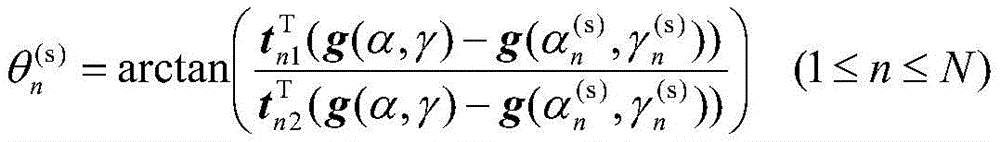
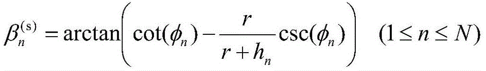
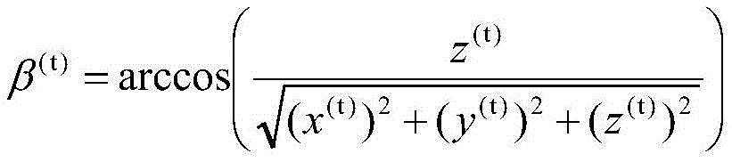
进一步地,所述步骤4中辐射源地理坐标与其发射的卫星信号到达单颗卫星的方位角和仰角之间的代数关系式为:Further, the algebraic relationship between the geographic coordinates of the radiation source and the azimuth angle and the elevation angle at which the satellite signal transmitted by the radiation source reaches a single satellite in the

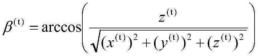
式中,θ(t)和β(t)分别为待定位辐射源发射的卫星信号到达单颗卫星的方位角和仰角,x(t)、y(t)和z(t)表示待定位辐射源在单颗卫星坐标系下的三维坐标:In the formula, θ (t) and β (t) are the azimuth and elevation angles of the satellite signal emitted by the radiation source to be located reaching a single satellite, respectively, and x (t) , y (t) and z (t) represent the radiation to be located. 3D coordinates of the source in a single satellite coordinate system:

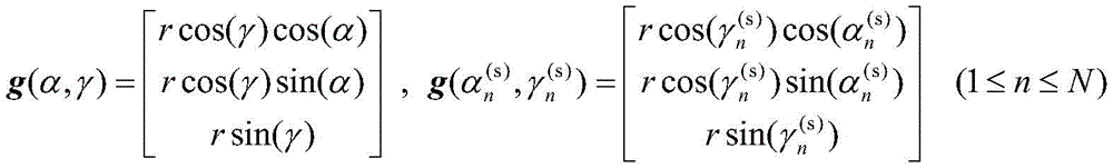
其中Px(ψx)、Py(ψy)和Pz(ψz)表示旋转矩阵,α(t)和γ(t)分别表示单颗卫星的经纬度,ψx、ψy及ψz分别表示单颗卫星绕x轴、y轴及z轴旋转的姿态角;g(α(t),γ(t))表示单颗卫星在地心地固坐标系下的位置向量:where P x (ψ x ), P y (ψ y ) and P z (ψ z ) represent the rotation matrix, α (t) and γ (t) represent the latitude and longitude of a single satellite, respectively, ψ x , ψ y and ψ z Represents the attitude angles of a single satellite rotating around the x-axis, y-axis and z-axis; g(α (t) , γ (t) ) represents the position vector of a single satellite in the earth-centered geo-fixed coordinate system:


进一步地,所述步骤5中单颗卫星的阵列接收信号模型为:Further, the array received signal model of a single satellite in the
x(t)(t)=b(t)(θ(t),β(t))s(t)(t)+ξ(t)(t)=f(t)(α,γ)s(t)(t)+ξ(t)(t)x (t) (t)=b (t) (θ (t) ,β (t) )s (t) (t)+ξ (t) (t)=f (t) (α,γ)s ( t) (t)+ξ (t) (t)
式中x(t)(t)表示单颗卫星中的均匀圆阵的接收信号;s(t)(t)表示信号到达单颗卫星的复包络;ξ(t)(t)表示阵列加性高斯白噪声,其均值为零、协方差矩阵为(σ(t))2IM(t),(σ(t))2表示噪声功率,IM(t)表示M(t)×M(t)阶单位矩阵,M(t)表示均匀圆阵的阵元个数;b(t)(θ(t),β(t))表示以信号二维波达方向为函数的阵列流形向量;f(t)(α,γ)表示以待定位辐射源地理坐标为函数的阵列流形向量,其满足:where x (t) (t) represents the received signal of a uniform circular array in a single satellite; s (t) (t) represents the complex envelope of the signal reaching a single satellite; ξ (t) (t) represents the array plus It is a white Gaussian noise whose mean is zero and the covariance matrix is (σ (t) ) 2 I M(t) , where (σ (t) ) 2 represents the noise power, and I M(t) represents M (t) ×M (t) order identity matrix, M (t) represents the number of elements of a uniform circular array; b (t) (θ (t) , β (t) ) represents the array manifold as a function of the two-dimensional direction of arrival of the signal vector; f (t) (α,γ) represents the array manifold vector as a function of the geographic coordinates of the radiation source to be located, which satisfies:

其中ρ(t)表示均匀圆阵的半径;λ(t)表示卫星信号的载波波长。where ρ (t) represents the radius of the uniform circular array; λ (t) represents the carrier wavelength of the satellite signal.
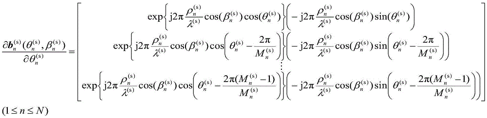
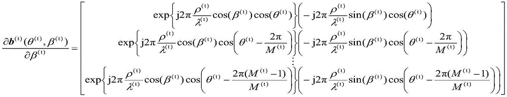
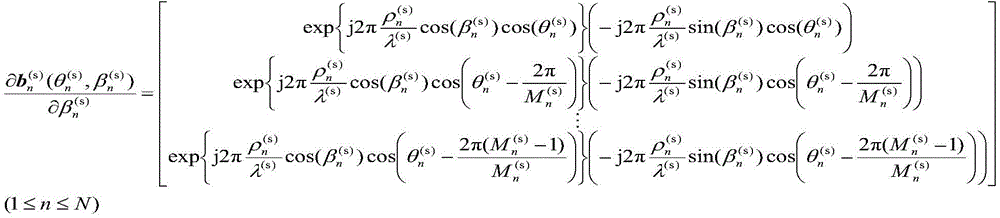
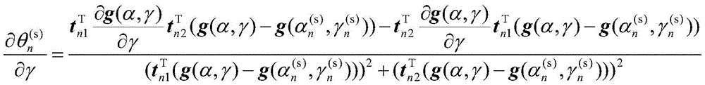
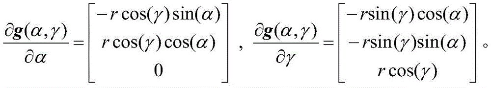
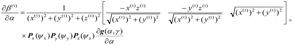
进一步地,所述步骤6中单颗卫星中的阵列流形向量关于地理坐标的导数表达式为:Further, the derivative expression of the array manifold vector in the single satellite in the


式中,


进一步地,所述直接定位优化模型为:Further, the direct positioning optimization model is:

式中J表示待优化的目标函数;tk表示第k个采样时刻;K表示信号采样点数。In the formula, J represents the objective function to be optimized; t k represents the kth sampling time; K represents the number of signal sampling points.
进一步地,所述步骤9包括:Further, the
步骤9.1:按照下式分别构造短波信号和卫星信号的阵列协方差矩阵:Step 9.1: Construct the array covariance matrix of shortwave signal and satellite signal respectively according to the following formula:

步骤9.2:依次对矩阵

由此可得噪声功率

步骤9.3:对矩阵

由此可得噪声功率(σ(t))2的估计值为:From this, the estimated value of noise power (σ (t) ) 2 can be obtained as:
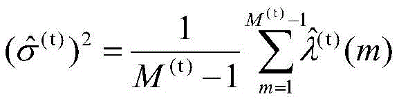
步骤9.4:按照下式依次求出

步骤9.5:按照下式依次求出{s(t)(tk)}1≤k≤K的最优解:Step 9.5: Find the optimal solution of {s (t) (t k )} 1≤k≤K according to the following formula:

步骤9.6:将

式中


其中,in,

进一步地,所述步骤10包括:Further, the
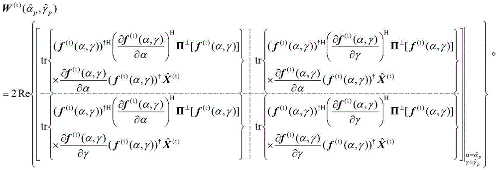
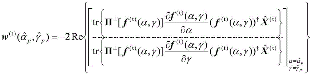
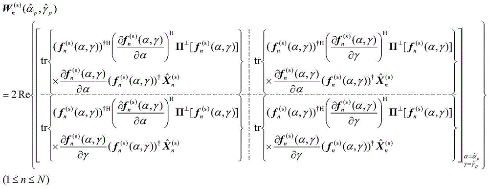
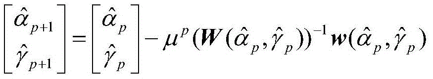
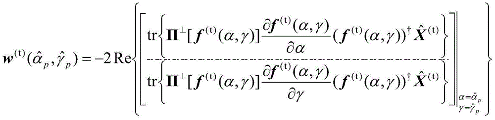
按照如下迭代公式对步骤9中的降维优化模型进行数值优化:The dimensionality reduction optimization model in
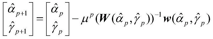
式中p表示迭代次数;


式中,In the formula,
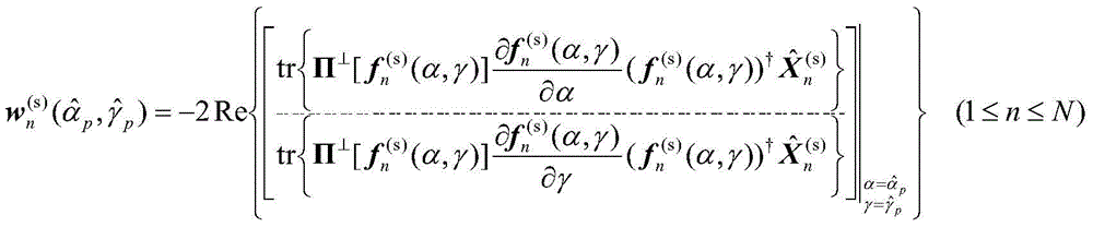


与现有技术相比,本发明具有的有益效果:Compared with the prior art, the present invention has the following beneficial effects:
本发明针对能够同时发射短波信号和卫星信号的待定位辐射源,首先利用多个短波观测站的地理坐标(即经纬度)和电离层虚高信息,依次建立该辐射源地理坐标(亦即经纬度)与其发射的短波信号到达不同短波观测站的方位角和仰角之间的代数关系式;然后利用每个短波观测站安装的均匀圆阵对该信号进行接收和采集,并确定短波观测站中的阵列流形向量关于地理坐标的导数表达式;接着利用单颗卫星的地理坐标和姿态角信息,建立该辐射源地理坐标与其发射的卫星信号到达单颗卫星的方位角和仰角之间的代数关系式;随后利用单颗卫星安装的均匀圆阵对该信号进行接收和采集,并确定单颗卫星中的阵列流形向量关于地理坐标的导数表达式;最后单颗卫星和各个短波观测站将采集得到的阵列信号数据传输至地面中心站进行处理,地面中心站基于短波信号数据和卫星信号数据获得估计辐射源经纬度的优化模型,并利用高斯-牛顿迭代法对其进行数值优化,用于获得辐射源经纬度的估计值,亦即最终的定位结果。相比已有的基于二维波达方向的短波多站定位和单星定位,本发明将短波多站定位和单星定位进行了有效协同,从而产生了协同增益,可以显著提升对地球表面远距离辐射源的定位精度。Aiming at the radiation source to be located that can transmit shortwave signals and satellite signals at the same time, the present invention firstly uses the geographic coordinates (ie latitude and longitude) of multiple shortwave observation stations and the ionospheric virtual height information to sequentially establish the geographic coordinates (ie latitude and longitude) of the radiation source. The algebraic relationship between the azimuth and elevation angles of the transmitted shortwave signals arriving at different shortwave observation stations; then the uniform circular array installed at each shortwave observation station is used to receive and collect the signal, and the array in the shortwave observation station is determined. The derivative expression of the manifold vector with respect to the geographic coordinates; then use the geographic coordinates and attitude angle information of a single satellite to establish the algebraic relationship between the geographic coordinates of the radiation source and the azimuth and elevation angles of the satellite signals it transmits to reach a single satellite ; Then use the uniform circular array installed by a single satellite to receive and collect the signal, and determine the derivative expression of the array manifold vector in the single satellite with respect to the geographic coordinates; finally, the single satellite and each shortwave observation station will collect the The array signal data is transmitted to the ground central station for processing. The ground central station obtains an optimization model for estimating the longitude and latitude of the radiation source based on the short-wave signal data and satellite signal data, and uses the Gauss-Newton iteration method to numerically optimize it to obtain the radiation source. The estimated value of latitude and longitude, that is, the final positioning result. Compared with the existing short-wave multi-station positioning and single-satellite positioning based on the two-dimensional direction of arrival, the present invention effectively synergizes the short-wave multi-station positioning and single-satellite positioning, thereby generating a synergy gain, which can significantly improve the distance to the earth's surface. The positioning accuracy of the distance radiation source.
附图说明Description of drawings
图1为本发明实施例一种基于二维波达方向的短波多站和单星协同直接定位方法的基本流程图;Fig. 1 is a basic flow chart of a short-wave multi-station and single-satellite coordinated direct positioning method based on two-dimensional direction of arrival according to an embodiment of the present invention;
图2为短波定位几何示意图;Fig. 2 is a geometric schematic diagram of short-wave positioning;
图3为单颗卫星坐标系及方位角和仰角示意图;Figure 3 is a schematic diagram of a single satellite coordinate system and azimuth and elevation angles;
图4为短波和卫星信号数据传输示意图;4 is a schematic diagram of shortwave and satellite signal data transmission;
图5为3种方法的定位结果散布图;Figure 5 is a scatter diagram of the positioning results of the three methods;
图6为3种方法的定位均方根误差随着信噪比的变化曲线;Fig. 6 is the variation curve of the positioning root mean square error with the signal-to-noise ratio of the three methods;
图7为3种方法的定位均方根误差随着信号采样点数的变化曲线;Fig. 7 is the variation curve of the positioning root mean square error of the three methods with the number of signal sampling points;
图8为3种方法的定位均方根误差随着短波观测站中的均匀圆阵半径与波长比的变化曲线;Fig. 8 is the variation curve of the positioning root mean square error of the three methods with the uniform circular array radius and wavelength ratio in the shortwave observation station;
图9为3种方法的定位均方根误差随着单星中的均匀圆阵半径与波长比的变化曲线。Fig. 9 shows the variation curve of the RMSE of the three methods with the ratio of the radius to the wavelength of the uniform circular array in a single star.
具体实施方式Detailed ways
下面结合附图和具体的实施例对本发明做进一步的解释说明:The present invention will be further explained below in conjunction with the accompanying drawings and specific embodiments:
如图1所示,一种基于二维波达方向的短波多站和单星协同直接定位方法,包括:As shown in Figure 1, a short-wave multi-station and single-satellite cooperative direct positioning method based on two-dimensional direction of arrival includes:
步骤S101:针对能够同时发射短波信号和卫星信号的待定位辐射源,利用N(N>1)个短波观测站的地理坐标(即经纬度)和电离层虚高信息,依次建立该辐射源地理坐标与其发射的短波信号到达N个短波观测站的方位角和仰角之间的代数关系式;Step S101: For a radiation source to be located that can simultaneously transmit shortwave signals and satellite signals, use the geographic coordinates (ie latitude and longitude) of N (N>1) shortwave observation stations and the ionospheric virtual height information to sequentially establish the geographic coordinates of the radiation source. The algebraic relationship between the azimuth angle and the elevation angle of the transmitted shortwave signal reaching N shortwave observation stations;
步骤S102:针对待定位辐射源发射的短波信号,利用N个短波观测站安装的均匀圆阵对该信号进行接收和采集;Step S102: For the short-wave signal emitted by the radiation source to be positioned, receive and collect the signal by using a uniform circular array installed by N short-wave observation stations;
步骤S103:依次确定短波观测站中的阵列流形向量关于地理坐标的导数表达式;Step S103: successively determining the derivative expression of the array manifold vector in the shortwave observation station with respect to the geographic coordinates;
步骤S104:针对同时发射短波信号和卫星信号的待定位辐射源,利用单颗卫星的地理坐标和姿态角信息,建立该辐射源地理坐标与其发射的卫星信号到达单颗卫星的方位角和仰角之间的代数关系式;Step S104: For the radiation source to be located that simultaneously transmits short-wave signals and satellite signals, use the geographic coordinates and attitude angle information of a single satellite to establish the relationship between the geographic coordinates of the radiation source and the azimuth and elevation angles of the radiation source and the satellite signals it transmits to reach a single satellite. algebraic relation between;
步骤S105:针对待定位辐射源发射的卫星信号,利用单颗卫星安装的均匀圆阵对该信号进行接收和采集;Step S105: for the satellite signal emitted by the radiation source to be positioned, receive and collect the signal by using a uniform circular array installed on a single satellite;
步骤S106:确定单颗卫星中的阵列流形向量关于地理坐标的导数表达式;Step S106: Determine the derivative expression of the array manifold vector in a single satellite with respect to the geographic coordinates;
步骤S107:单颗卫星和各个短波观测站将采集得到的阵列信号数据传输至地面中心站进行处理;Step S107: the single satellite and each short-wave observation station transmit the collected array signal data to the ground central station for processing;
步骤S108:地面中心站基于短波信号数据和卫星信号数据,利用最大似然估计准则构建直接定位优化模型;Step S108: the ground central station uses the maximum likelihood estimation criterion to construct a direct positioning optimization model based on the shortwave signal data and the satellite signal data;
步骤S109:地面中心站针对步骤S108中构建的直接定位优化模型进行降维处理,得到仅关于辐射源经纬度的降维优化模型;Step S109: the ground central station performs dimension reduction processing on the direct positioning optimization model constructed in step S108, and obtains a dimension reduction optimization model only about the longitude and latitude of the radiation source;
步骤S110:地面中心站利用高斯-牛顿迭代法对步骤S109中的降维优化模型进行数值优化,用于获得辐射源经纬度的估计值,亦即最终的定位结果。Step S110: The ground central station uses the Gauss-Newton iteration method to perform numerical optimization on the dimensionality reduction optimization model in step S109, so as to obtain the estimated values of the longitude and latitude of the radiation source, that is, the final positioning result.
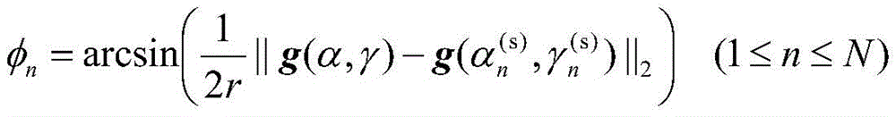
具体地,所述步骤S101中,假设第n个短波观测站的经纬度分别为


式中r表示地球半径;tn1和tn2均表示坐标系转换向量;φn表示第n个短波观测站与辐射源之间的地心角的一半;g(α,γ)表示待定位辐射源在地心地固坐标系下的位置向量;


具体地,所述步骤S102中,针对待定位辐射源发射的短波信号,利用N个短波观测站安装的均匀圆阵对该信号进行接收和采集,其中第n个短波观测站的阵列接收信号模型为:Specifically, in the step S102, for the short-wave signal emitted by the radiation source to be positioned, the uniform circular array installed by N short-wave observation stations is used to receive and collect the signal, wherein the array of the n-th short-wave observation station receives and collects the signal model. for:

式中


其中
具体地,所述步骤S103中短波观测站中的阵列流形向量关于地理坐标的导数表达式为:Specifically, in the step S103, the derivative expression of the array manifold vector in the shortwave observation station with respect to the geographic coordinates is:


式中,


其中,in,

具体地,所述步骤S104中,假设单颗卫星的经纬度分别为α(t)和γ(t),其绕x轴旋转的姿态角为ψx(称为滚动),绕y轴旋转的姿态角为ψy(称为俯仰),绕z轴旋转的姿态角为ψz(称为航偏),待定位辐射源发射的卫星信号到达单颗卫星的方位角和仰角分别为θ(t)和β(t)(如图3所示),于是可以建立如下代数关系式:Specifically, in the step S104, it is assumed that the longitude and latitude of a single satellite are α (t) and γ (t) respectively, the attitude angle of its rotation around the x -axis is ψx (called roll), and the attitude of rotation around the y-axis is The angle is ψ y (called pitch), the attitude angle of rotation around the z-axis is ψ z (called yaw), and the azimuth angle and elevation angle of the satellite signal emitted by the radiation source to be positioned to reach a single satellite are θ (t) and β (t) (as shown in Figure 3), then the following algebraic relationship can be established:


式中x(t)、y(t)和z(t)表示待定位辐射源在单颗卫星坐标系下的三维坐标,它们的表达式如下:where x (t) , y (t) and z (t) represent the three-dimensional coordinates of the radiation source to be positioned in a single satellite coordinate system, and their expressions are as follows:

其中Px(ψx),Py(ψy)和Pz(ψz)表示旋转矩阵;g(α(t),γ(t))表示单颗卫星在地心地固坐标系下的位置向量,它们的表达式如下:where P x (ψ x ), P y (ψ y ) and P z (ψ z ) represent rotation matrices; g(α (t) , γ (t) ) represent the position of a single satellite in the geocentric geofixed coordinate system vectors, their expressions are as follows:


具体地,所述步骤S105中单颗卫星的阵列接收信号模型为:Specifically, the array received signal model of a single satellite in the step S105 is:
x(t)(t)=b(t)(θ(t),β(t))s(t)(t)+ξ(t)(t)=f(t)(α,γ)s(t)(t)+ξ(t)(t)x (t) (t)=b (t) (θ (t) ,β (t) )s (t) (t)+ξ (t) (t)=f (t) (α,γ)s ( t) (t)+ξ (t) (t)
式中x(t)(t)表示单颗卫星中的均匀圆阵的接收信号;s(t)(t)表示信号到达单颗卫星的复包络;ξ(t)(t)表示阵列加性高斯白噪声,其均值为零、协方差矩阵为


其中ρ(t)表示均匀圆阵的半径;λ(t)表示卫星信号的载波波长。where ρ (t) represents the radius of the uniform circular array; λ (t) represents the carrier wavelength of the satellite signal.
具体地,所述步骤S106中单颗卫星中的阵列流形向量关于地理坐标的导数表达式为:Specifically, in the step S106, the derivative expression of the array manifold vector in the single satellite with respect to the geographic coordinates is:


式中,


具体地,所述步骤S107中,单颗卫星和各个短波观测站将采集得到的阵列信号数据传输至地面中心站进行处理,如图4所示,可以将第个短波观测站作为地面中心站,其可以同时接收短波信号和卫星信号。Specifically, in the step S107, the single satellite and each shortwave observation station transmit the collected array signal data to the ground central station for processing. As shown in FIG. 4, the th shortwave observation station can be used as the ground central station, It can receive both shortwave and satellite signals at the same time.
具体地,所述直接定位优化模型为:Specifically, the direct positioning optimization model is:

式中J表示待优化的目标函数;tk表示第k个采样时刻;K表示信号采样点数。In the formula, J represents the objective function to be optimized; t k represents the kth sampling time; K represents the number of signal sampling points.
具体地,所述步骤S109包括:Specifically, the step S109 includes:
步骤S109.1:分别构造短波信号和卫星信号的阵列协方差矩阵,如下式所示:Step S109.1: Construct the array covariance matrix of the shortwave signal and the satellite signal respectively, as shown in the following formula:

步骤S109.2:分依次对矩阵

由此可得噪声功率

步骤S109.3:分对矩阵

由此可得噪声功率(σ(t))2的估计值为From this, the estimated value of noise power (σ (t) ) 2 can be obtained as

步骤S109.4:依次求出

步骤S109.5:依次求出{s(t)(tk)}1≤k≤K的最优解,如下式所示Step S109.5: Find the optimal solution of {s (t) (t k )} 1≤k≤K in sequence, as shown in the following formula

步骤S109.6:将

式中


其中,in,

具体地,所述步骤S110包括:Specifically, the step S110 includes:
所述步骤S110中,地面中心站利用高斯-牛顿迭代法对步骤S109中的降维优化模型进行数值优化,用于获得辐射源经纬度的估计值,亦即最终的定位结果,其迭代公式如下:In the step S110, the ground central station uses the Gauss-Newton iteration method to numerically optimize the dimensionality reduction optimization model in the step S109, so as to obtain the estimated value of the longitude and latitude of the radiation source, that is, the final positioning result. The iterative formula is as follows:

式中p表示迭代次数;


式中in the formula


为验证本发明效果,进行如下实验:In order to verify the effect of the present invention, the following experiments are carried out:
假设有3个短波观测站和单颗通信卫星对地球表面的辐射源进行定位,3个短波观测站的经度分别为119.1°,119.4°和117.3°,纬度分别为31.7°,25.6°和36.4°,卫星的经度为128.56°,纬度为24.44°,其轨道高度为800km,辐射源的经度为132.45°,纬度为22.61°,其同时发射短波信号和卫星信号,其中短波信号到达3个短波观测站所经历的电离层高度分别为350km,320km和280km。短波观测站中的均匀圆阵阵元个数均为20,单星中的均匀圆阵阵元个数为9。下面将本专利公开的定位方法与传统的短波多站定位方法和单星定位方法进行比较。It is assumed that there are 3 shortwave observation stations and a single communication satellite to locate the radiation source on the earth's surface. The longitudes of the 3 shortwave observation stations are 119.1°, 119.4° and 117.3°, and the latitudes are 31.7°, 25.6° and 36.4°, respectively. , the longitude of the satellite is 128.56°, the latitude is 24.44°, its orbital altitude is 800km, the longitude of the radiation source is 132.45°, the latitude is 22.61°, and it simultaneously transmits shortwave signals and satellite signals, of which the shortwave signals arrive at 3 shortwave observation stations The ionospheric altitudes experienced were 350km, 320km and 280km, respectively. The number of uniform circular array elements in the shortwave observatory is 20, and the number of uniform circular array elements in a single star is 9. The following will compare the positioning method disclosed in this patent with the traditional short-wave multi-station positioning method and single-satellite positioning method.
首先将短波观测站中的均匀圆阵半径与波长比设为1,单星中的圆阵半径与波长比设为2,信噪比设为5dB,信号采样点数设为1000,图5给出了3种方法(短波多站定位方法,单星定位方法及本专利公开的定位方法)的定位结果散布图,其中一共进行了5000次蒙特卡洛实验。从图5中可以看出,短波多站定位方法在辐射源纬度方向上的定位误差较大,单星定位方法在辐射源经度方向上的定位误差较大,而本专利公开的定位方法则在纬度方向和经度方向上的定位误差都能得到降低。经过数值统计可知,短波多站定位方法的定位误差为2.3269km,单星定位方法的定位误差为5.3384km,而本专利公开的定位方法的定位误差为1.4329km,其定位精度是最高的。First, set the ratio of the radius to wavelength of the uniform circular array in the shortwave observation station to 1, set the ratio of the radius to the wavelength of the circular array in a single satellite to 2, set the signal-to-noise ratio to 5dB, and set the number of signal sampling points to 1000, as shown in Figure 5. The scatter diagrams of the positioning results of the three methods (short-wave multi-station positioning method, single-star positioning method and the positioning method disclosed in this patent) are obtained, and a total of 5000 Monte Carlo experiments have been carried out. It can be seen from Figure 5 that the short-wave multi-station positioning method has a large positioning error in the latitude direction of the radiation source, and the single-satellite positioning method has a large positioning error in the longitude direction of the radiation source, while the positioning method disclosed in this patent is in Positioning errors in both latitude and longitude directions can be reduced. Numerical statistics show that the positioning error of the short-wave multi-station positioning method is 2.3269 km, the positioning error of the single-satellite positioning method is 5.3384 km, and the positioning error of the positioning method disclosed in this patent is 1.4329 km, and its positioning accuracy is the highest.
其余条件不变,图6给出了3种方法(短波多站定位方法,单星定位方法及本专利公开的定位方法)的定位均方根误差随着信噪比的变化曲线,图7给出了3种方法的定位均方根误差随着信号采样点数的变化曲线,图8给出了3种方法的定位均方根误差随着短波观测站中的均匀圆阵半径与波长比的变化曲线,图9给出了3种方法的定位均方根误差随着单星中的均匀圆阵半径与波长比的变化曲线。从中可以看出,相比于短波多站定位方法和单星定位方法,本专利公开的定位方法具有更高的定位精度,因为本专利公开的定位方法是将短波多站定位和单星定位进行了有效协同,因而产生了协同增益,提高了定位精度。The rest of the conditions remain unchanged. Figure 6 shows the variation curve of the positioning root mean square error with the signal-to-noise ratio of the three methods (short-wave multi-station positioning method, single-satellite positioning method and the positioning method disclosed in this patent). The variation curves of the positioning RMS error of the three methods with the number of signal sampling points are shown. Figure 8 shows the positioning root mean square error of the three methods with the change of the uniform circle radius and wavelength ratio in the short-wave observation station. Curves, Figure 9 shows the RMSE of the three methods as a function of the ratio of the radius to the wavelength of the uniform circular array in a single star. It can be seen from this that, compared with the short-wave multi-station positioning method and the single-satellite positioning method, the positioning method disclosed in this patent has higher positioning accuracy, because the positioning method disclosed in this patent is to perform short-wave multi-station positioning and single-satellite positioning. In order to achieve effective coordination, the synergy gain is generated and the positioning accuracy is improved.
以上所示仅是本发明的优选实施方式,应当指出,对于本技术领域的普通技术人员来说,在不脱离本发明原理的前提下,还可以做出若干改进和润饰,这些改进和润饰也应视为本发明的保护范围。The above are only the preferred embodiments of the present invention. It should be pointed out that for those skilled in the art, without departing from the principles of the present invention, several improvements and modifications can be made. It should be regarded as the protection scope of the present invention.
Claims (8)


Priority Applications (1)
| Application Number | Priority Date | Filing Date | Title |
|---|---|---|---|
| CN202010095378.XA CN111308530B (en) | 2020-02-17 | 2020-02-17 | Short wave multi-station and single-satellite cooperative direct positioning method based on two-dimensional direction of arrival |
Applications Claiming Priority (1)
| Application Number | Priority Date | Filing Date | Title |
|---|---|---|---|
| CN202010095378.XA CN111308530B (en) | 2020-02-17 | 2020-02-17 | Short wave multi-station and single-satellite cooperative direct positioning method based on two-dimensional direction of arrival |
Publications (2)
| Publication Number | Publication Date |
|---|---|
| CN111308530A CN111308530A (en) | 2020-06-19 |
| CN111308530B true CN111308530B (en) | 2021-12-03 |
Family
ID=71160015
Family Applications (1)
| Application Number | Title | Priority Date | Filing Date |
|---|---|---|---|
| CN202010095378.XA Active CN111308530B (en) | 2020-02-17 | 2020-02-17 | Short wave multi-station and single-satellite cooperative direct positioning method based on two-dimensional direction of arrival |
Country Status (1)
| Country | Link |
|---|---|
| CN (1) | CN111308530B (en) |
Families Citing this family (7)
| Publication number | Priority date | Publication date | Assignee | Title |
|---|---|---|---|---|
| CN112782647B (en) * | 2020-12-15 | 2023-05-16 | 中国人民解放军战略支援部队信息工程大学 | Information-combined quadratic constraint least square radiation source positioning method |
| CN113281701B (en) * | 2021-04-28 | 2024-03-12 | 中国人民解放军战略支援部队信息工程大学 | Direct over-the-horizon target positioning method using shortwave multi-station angles and Samsung time difference |
| CN113281702B (en) * | 2021-04-30 | 2024-02-09 | 中国人民解放军战略支援部队信息工程大学 | Direct over-the-horizon target positioning method using shortwave multi-station angles and satellite time-frequency |
| CN115128651B (en) * | 2022-06-02 | 2024-10-22 | 武汉大学 | Radiation source positioning method based on satellite platform sensor system |
| CN115168788B (en) * | 2022-09-07 | 2022-11-22 | 中国科学院空天信息创新研究院 | Method, device, equipment and medium for determining satellite remote sensing big data |
| CN116165599B (en) * | 2023-04-24 | 2023-06-27 | 武汉能钠智能装备技术股份有限公司四川省成都市分公司 | Ultrashort wave direction finding system and integrated ultrashort wave direction finding equipment |
| CN118011313B (en) * | 2024-04-09 | 2024-06-11 | 中国航天科工集团八五一一研究所 | A method for sorting pulse direction finding information based on Gaussian mixture model |
Citations (2)
| Publication number | Priority date | Publication date | Assignee | Title |
|---|---|---|---|---|
| CN110609021A (en) * | 2019-08-15 | 2019-12-24 | 成都市环境保护科学研究院 | River basin pollutant characteristic analysis method based on three-dimensional fluorescence spectrum |
| CN110687502A (en) * | 2019-09-18 | 2020-01-14 | 中国人民解放军战略支援部队信息工程大学 | A method for labeling shortwave direction finding datasets based on least squares positioning |
Family Cites Families (19)
| Publication number | Priority date | Publication date | Assignee | Title |
|---|---|---|---|---|
| JPH11296792A (en) * | 1998-04-09 | 1999-10-29 | Hitachi Ltd | Road-to-vehicle receiver |
| CN101262690B (en) * | 2007-03-08 | 2010-12-08 | 北京海洋信通网络技术服务有限公司 | Ocean ultra-short wave remote wireless communication and integrated information service system |
| RU2523650C2 (en) * | 2012-04-03 | 2014-07-20 | Федеральное государственное военное образовательное учреждение высшего профессионального образования "Военный авиационный инженерный университет" (г. Воронеж) Министерства обороны Российской Федерации | Method for single-step location of short-wave radiation source |
| CN103096465B (en) * | 2013-01-11 | 2015-06-24 | 南京师范大学 | Environment self-adaption multi-target direct locating method |
| CA2930832A1 (en) * | 2013-11-17 | 2015-05-21 | Quantum-Si Incorporated | Optical system and assay chip for probing, detecting and analyzing molecules |
| US9304680B2 (en) * | 2013-11-25 | 2016-04-05 | At&T Mobility Ii Llc | Methods, devices, and computer readable storage device for touchscreen navigation |
| CN105487063A (en) * | 2015-12-26 | 2016-04-13 | 中国人民解放军信息工程大学 | Direct positioning method based on external radiation source time delay and Doppler frequency |
| CN105759241B (en) * | 2015-12-18 | 2018-09-04 | 中国航天科工集团八五一一研究所 | Direct localization method based on time difference frequency difference |
| CN107290717B (en) * | 2017-05-19 | 2019-07-26 | 中国人民解放军信息工程大学 | Multi-target direct positioning method for non-circular signals |
| WO2019143657A1 (en) * | 2018-01-18 | 2019-07-25 | Hysky Technologies, Inc. | Hihg frequency geo-location methods and systems |
| CN108957387B (en) * | 2018-05-21 | 2022-06-21 | 西安电子科技大学 | A two-dimensional angle of arrival estimation method and system for satellite signals |
| CN108828568A (en) * | 2018-07-19 | 2018-11-16 | 中国人民解放军战略支援部队信息工程大学 | A kind of direct localization method and system of single moving observer |
| CN109298388B (en) * | 2018-08-21 | 2020-09-18 | 中国人民解放军战略支援部队信息工程大学 | Direct estimation method of over-the-horizon target geographic coordinates based on azimuth information |
| CN109613583B (en) * | 2019-01-02 | 2023-05-26 | 电子科技大学 | Passive target positioning method based on single star and ground station direction finding and combined time difference |
| CN109975755B (en) * | 2019-02-26 | 2021-04-20 | 中国人民解放军战略支援部队信息工程大学 | A direct positioning method for shortwave multi-station under the condition of correction source |
| CN109975749B (en) * | 2019-02-26 | 2021-04-20 | 中国人民解放军战略支援部队信息工程大学 | A direct positioning method of shortwave single station under the condition of correction source |
| CN109991564B (en) * | 2019-02-26 | 2022-12-13 | 中国人民解放军战略支援部队信息工程大学 | Deviation correction method for shortwave single-station positioning results based on neural network |
| CN110389327A (en) * | 2019-07-29 | 2019-10-29 | 杭州电子科技大学 | The more external illuminators-based radars of multistation are biradical away from localization method under receiving station's location error |
| CN110568403B (en) * | 2019-08-10 | 2023-02-17 | 中国人民解放军战略支援部队信息工程大学 | A method for passive positioning of over-the-horizon targets based on coordinated short-wave and satellite systems |
-
2020
- 2020-02-17 CN CN202010095378.XA patent/CN111308530B/en active Active
Patent Citations (2)
| Publication number | Priority date | Publication date | Assignee | Title |
|---|---|---|---|---|
| CN110609021A (en) * | 2019-08-15 | 2019-12-24 | 成都市环境保护科学研究院 | River basin pollutant characteristic analysis method based on three-dimensional fluorescence spectrum |
| CN110687502A (en) * | 2019-09-18 | 2020-01-14 | 中国人民解放军战略支援部队信息工程大学 | A method for labeling shortwave direction finding datasets based on least squares positioning |
Also Published As
| Publication number | Publication date |
|---|---|
| CN111308530A (en) | 2020-06-19 |
Similar Documents
| Publication | Publication Date | Title |
|---|---|---|
| CN111308530B (en) | Short wave multi-station and single-satellite cooperative direct positioning method based on two-dimensional direction of arrival | |
| CN109975749B (en) | A direct positioning method of shortwave single station under the condition of correction source | |
| CN109975755B (en) | A direct positioning method for shortwave multi-station under the condition of correction source | |
| CN109298388B (en) | Direct estimation method of over-the-horizon target geographic coordinates based on azimuth information | |
| CN111199280B (en) | Multi-station target source geographic coordinate estimation method combining signal complex envelope and carrier phase information in presence of short wave channel model error | |
| CN111199281B (en) | A short-wave single-station direct positioning error compensation method based on the spatial location spectrum of geographic coordinates | |
| CN113009477B (en) | Array type high-frequency ground wave ocean radar system | |
| CN110568403B (en) | A method for passive positioning of over-the-horizon targets based on coordinated short-wave and satellite systems | |
| CN109975754A (en) | The direct localization method of movement multistation of joint angle, time delay and doppler information | |
| CN108562902A (en) | Height rail double-base SAR configuration designing method based on simulated annealing | |
| CN110297213A (en) | Radiation source positioning device and method based on the unmanned aerial vehicle platform for loading relatively prime linear array | |
| CN114910934A (en) | Sea surface vector wind field inversion system and method based on satellite-borne GNSS-R/S integrated receiving | |
| CN108872932A (en) | Correction method of over-the-horizon target direct positioning result based on neural network | |
| CN113281701A (en) | Beyond-the-horizon target direct positioning method of cooperative short wave multi-station angle and three-star time difference | |
| CN108957387A (en) | A kind of satellite-signal two-dimentional angle estimation method and system | |
| CN118746811A (en) | A multi-station fusion two-level weighted constant false alarm detection method based on satellite radiation source | |
| CN109991564B (en) | Deviation correction method for shortwave single-station positioning results based on neural network | |
| CN113281702B (en) | Direct over-the-horizon target positioning method using shortwave multi-station angles and satellite time-frequency | |
| CN114325768A (en) | Deception jamming identification method and system based on auxiliary of aircraft | |
| CN117233697A (en) | A distributed array collaborative direct positioning method for multiple narrowband signal moving radiation sources | |
| Zou et al. | Orbit determination algorithm and performance analysis of high‐orbit spacecraft based on GNSS | |
| Yang et al. | A novel land-based high-frequency geolocation system | |
| CN115128651B (en) | Radiation source positioning method based on satellite platform sensor system | |
| CN111079929B (en) | Short-wave single-station multi-target geographical coordinate rapid estimation method based on neural calculation | |
| CN113203985B (en) | Direct positioning method for shortwave same-frequency signals |
Legal Events
| Date | Code | Title | Description |
|---|---|---|---|
| PB01 | Publication | ||
| PB01 | Publication | ||
| SE01 | Entry into force of request for substantive examination | ||
| SE01 | Entry into force of request for substantive examination | ||
| GR01 | Patent grant | ||
| GR01 | Patent grant | ||
| CP03 | Change of name, title or address |
Address after: 450000 Science Avenue 62, Zhengzhou High-tech Zone, Henan Province Patentee after: Information Engineering University of the Chinese People's Liberation Army Cyberspace Force Country or region after: China Address before: No. 62 Science Avenue, High tech Zone, Zhengzhou City, Henan Province Patentee before: Information Engineering University of Strategic Support Force,PLA Country or region before: China |
|
| CP03 | Change of name, title or address |