CN111290001A - Target overall planning method, device and equipment based on GPS coordinates - Google Patents
Target overall planning method, device and equipment based on GPS coordinates Download PDFInfo
- Publication number
- CN111290001A CN111290001A CN201811485122.9A CN201811485122A CN111290001A CN 111290001 A CN111290001 A CN 111290001A CN 201811485122 A CN201811485122 A CN 201811485122A CN 111290001 A CN111290001 A CN 111290001A
- Authority
- CN
- China
- Prior art keywords
- area
- tracking
- tracking target
- coordinate
- target
- Prior art date
- Legal status (The legal status is an assumption and is not a legal conclusion. Google has not performed a legal analysis and makes no representation as to the accuracy of the status listed.)
- Pending
Links
Images


Classifications
-
- H—ELECTRICITY
- H04—ELECTRIC COMMUNICATION TECHNIQUE
- H04N—PICTORIAL COMMUNICATION, e.g. TELEVISION
- H04N23/00—Cameras or camera modules comprising electronic image sensors; Control thereof
- H04N23/60—Control of cameras or camera modules
- H04N23/698—Control of cameras or camera modules for achieving an enlarged field of view, e.g. panoramic image capture
-
- G—PHYSICS
- G01—MEASURING; TESTING
- G01S—RADIO DIRECTION-FINDING; RADIO NAVIGATION; DETERMINING DISTANCE OR VELOCITY BY USE OF RADIO WAVES; LOCATING OR PRESENCE-DETECTING BY USE OF THE REFLECTION OR RERADIATION OF RADIO WAVES; ANALOGOUS ARRANGEMENTS USING OTHER WAVES
- G01S19/00—Satellite radio beacon positioning systems; Determining position, velocity or attitude using signals transmitted by such systems
- G01S19/01—Satellite radio beacon positioning systems transmitting time-stamped messages, e.g. GPS [Global Positioning System], GLONASS [Global Orbiting Navigation Satellite System] or GALILEO
- G01S19/13—Receivers
- G01S19/24—Acquisition or tracking or demodulation of signals transmitted by the system
-
- G—PHYSICS
- G06—COMPUTING OR CALCULATING; COUNTING
- G06T—IMAGE DATA PROCESSING OR GENERATION, IN GENERAL
- G06T7/00—Image analysis
- G06T7/20—Analysis of motion
- G06T7/246—Analysis of motion using feature-based methods, e.g. the tracking of corners or segments
-
- G—PHYSICS
- G08—SIGNALLING
- G08B—SIGNALLING OR CALLING SYSTEMS; ORDER TELEGRAPHS; ALARM SYSTEMS
- G08B13/00—Burglar, theft or intruder alarms
- G08B13/18—Actuation by interference with heat, light, or radiation of shorter wavelength; Actuation by intruding sources of heat, light, or radiation of shorter wavelength
- G08B13/189—Actuation by interference with heat, light, or radiation of shorter wavelength; Actuation by intruding sources of heat, light, or radiation of shorter wavelength using passive radiation detection systems
- G08B13/194—Actuation by interference with heat, light, or radiation of shorter wavelength; Actuation by intruding sources of heat, light, or radiation of shorter wavelength using passive radiation detection systems using image scanning and comparing systems
- G08B13/196—Actuation by interference with heat, light, or radiation of shorter wavelength; Actuation by intruding sources of heat, light, or radiation of shorter wavelength using passive radiation detection systems using image scanning and comparing systems using television cameras
- G08B13/19602—Image analysis to detect motion of the intruder, e.g. by frame subtraction
- G08B13/19608—Tracking movement of a target, e.g. by detecting an object predefined as a target, using target direction and or velocity to predict its new position
-
- G—PHYSICS
- G08—SIGNALLING
- G08B—SIGNALLING OR CALLING SYSTEMS; ORDER TELEGRAPHS; ALARM SYSTEMS
- G08B13/00—Burglar, theft or intruder alarms
- G08B13/18—Actuation by interference with heat, light, or radiation of shorter wavelength; Actuation by intruding sources of heat, light, or radiation of shorter wavelength
- G08B13/189—Actuation by interference with heat, light, or radiation of shorter wavelength; Actuation by intruding sources of heat, light, or radiation of shorter wavelength using passive radiation detection systems
- G08B13/194—Actuation by interference with heat, light, or radiation of shorter wavelength; Actuation by intruding sources of heat, light, or radiation of shorter wavelength using passive radiation detection systems using image scanning and comparing systems
- G08B13/196—Actuation by interference with heat, light, or radiation of shorter wavelength; Actuation by intruding sources of heat, light, or radiation of shorter wavelength using passive radiation detection systems using image scanning and comparing systems using television cameras
- G08B13/19639—Details of the system layout
- G08B13/19645—Multiple cameras, each having view on one of a plurality of scenes, e.g. multiple cameras for multi-room surveillance or for tracking an object by view hand-over
-
- H—ELECTRICITY
- H04—ELECTRIC COMMUNICATION TECHNIQUE
- H04N—PICTORIAL COMMUNICATION, e.g. TELEVISION
- H04N7/00—Television systems
- H04N7/18—Closed-circuit television [CCTV] systems, i.e. systems in which the video signal is not broadcast
- H04N7/181—Closed-circuit television [CCTV] systems, i.e. systems in which the video signal is not broadcast for receiving images from a plurality of remote sources
-
- G—PHYSICS
- G06—COMPUTING OR CALCULATING; COUNTING
- G06T—IMAGE DATA PROCESSING OR GENERATION, IN GENERAL
- G06T2207/00—Indexing scheme for image analysis or image enhancement
- G06T2207/30—Subject of image; Context of image processing
- G06T2207/30232—Surveillance
-
- G—PHYSICS
- G06—COMPUTING OR CALCULATING; COUNTING
- G06T—IMAGE DATA PROCESSING OR GENERATION, IN GENERAL
- G06T2207/00—Indexing scheme for image analysis or image enhancement
- G06T2207/30—Subject of image; Context of image processing
- G06T2207/30236—Traffic on road, railway or crossing
Landscapes
- Engineering & Computer Science (AREA)
- Multimedia (AREA)
- Signal Processing (AREA)
- Physics & Mathematics (AREA)
- General Physics & Mathematics (AREA)
- Radar, Positioning & Navigation (AREA)
- Remote Sensing (AREA)
- Computer Vision & Pattern Recognition (AREA)
- Computer Networks & Wireless Communication (AREA)
- Theoretical Computer Science (AREA)
- Studio Devices (AREA)
- Alarm Systems (AREA)
Abstract
本发明实施例提供了一种基于GPS坐标的目标统筹方法、装置及设备,方法包括:获取每个跟踪目标的GPS坐标;针对预先划分的每个区域,基于获取到的每个跟踪目标的GPS坐标,统计位于该区域的跟踪目标的数量;根据每个区域的跟踪目标的数量,生成跟踪目标的热度图。可见,本方案中,由一台设备基于各跟踪目标的GPS坐标,生成热度图,该热度图可以展现各个区域的跟踪目标的数量,实现了对跟踪目标的统筹。

Embodiments of the present invention provide a method, device, and device for target coordination based on GPS coordinates. The method includes: obtaining GPS coordinates of each tracking target; for each pre-divided area, based on the obtained GPS coordinates of each tracking target Coordinates, count the number of tracking targets located in the area; generate a heat map of the tracking targets according to the number of tracking targets in each area. It can be seen that in this solution, a device generates a heat map based on the GPS coordinates of each tracking target, and the heat map can display the number of tracking targets in each area, realizing the overall planning of the tracking targets.
Description
技术领域technical field
本发明涉及安防技术领域,特别是涉及一种基于GPS坐标的目标统筹方 法、装置及设备。The present invention relates to the technical field of security, and in particular, to a method, device and equipment for target coordination based on GPS coordinates.
背景技术Background technique
一些场景中,通过摄像机采集的监控图像,可以对车辆、人员等跟踪目标 进行跟踪。跟踪方案可以包括:在第N帧图像中,检测待跟踪的跟踪目标,通 过目标跟踪算法,确定第N+1帧图像及后续图像中该跟踪目标的位置,将该 位置转换为GPS坐标,如GPS坐标。这样,便可以连续获取到该跟踪目标的 GPS坐标,实现了对该跟踪目标的跟踪。In some scenarios, tracking targets such as vehicles and people can be tracked through surveillance images collected by cameras. The tracking scheme may include: in the Nth frame image, detecting the tracking target to be tracked, determining the position of the tracking target in the N+1th frame image and subsequent images through a target tracking algorithm, and converting the position into GPS coordinates, such as GPS coordinates. In this way, the GPS coordinates of the tracking target can be continuously obtained, thereby realizing the tracking of the tracking target.
在较大的区域中,通常存在较多的跟踪目标,需要多台摄像机对这些跟踪 目标进行跟踪。但是目前,并没有对这些跟踪目标进行统筹的方案。In a larger area, there are usually many tracking targets, and multiple cameras are required to track these tracking targets. However, at present, there is no plan for coordinating these tracking targets.
发明内容SUMMARY OF THE INVENTION
本发明实施例的目的在于提供一种基于GPS坐标的目标统筹方法、装置 及设备,以对跟踪目标进行统筹。The purpose of the embodiments of the present invention is to provide a target planning method, device and device based on GPS coordinates, so as to coordinate tracking targets.
为了达到上述目的,本发明实施例提供了一种基于GPS坐标的目标统筹方 法,包括:In order to achieve the above object, the embodiment of the present invention provides a kind of target overall planning method based on GPS coordinates, including:
获取每个跟踪目标的GPS坐标;Get the GPS coordinates of each tracking target;
针对预先划分的每个区域,基于获取到的每个跟踪目标的GPS坐标,统计 位于该区域的跟踪目标的数量;For each pre-divided area, based on the GPS coordinates of each tracking target obtained, count the number of tracking targets located in this area;
根据每个区域的跟踪目标的数量,生成跟踪目标的热度图。Based on the number of tracked targets in each area, a heatmap of tracked targets is generated.
可选的,所述获取每个跟踪目标的GPS坐标,包括:Optionally, the obtaining the GPS coordinates of each tracking target includes:
接收每台摄像机发送的监控图像,识别所述监控图像中的跟踪目标,将所 述跟踪目标在所述监控图像坐标系中的坐标转换为GPS坐标;Receive the monitoring image sent by each camera, identify the tracking target in the monitoring image, and convert the coordinates of the tracking target in the monitoring image coordinate system into GPS coordinates;
或者,接收每台摄像机发送的数据包,所述数据包中包括每个跟踪目标的GPS坐标。Alternatively, a data packet sent by each camera is received, and the data packet includes the GPS coordinates of each tracking target.
可选的,所述将所述跟踪目标在所述监控图像坐标系中的坐标转换为GPS 坐标,包括:Optionally, converting the coordinates of the tracking target in the monitoring image coordinate system into GPS coordinates includes:
在预先设定的各标定点组中,选择与所述跟踪目标的距离满足预设距离条 件的标定点组,作为目标标定点组;In each preset calibration point group, select the calibration point group whose distance from the tracking target satisfies the preset distance condition as the target calibration point group;
基于预先获取的、针对所述目标标定点组标定得到的单应性矩阵,将所述 跟踪目标在所述监控图像坐标系中的坐标转换为GPS坐标。Based on the homography matrix obtained in advance and calibrated for the target calibration point group, the coordinates of the tracking target in the monitoring image coordinate system are converted into GPS coordinates.
可选的,所述获取每个跟踪目标的GPS坐标,包括:Optionally, the obtaining the GPS coordinates of each tracking target includes:
获取球机拍摄跟踪目标时的PT坐标,作为第一P坐标和第一T坐标;Obtain the PT coordinates when the dome camera shoots and track the target, as the first P coordinate and the first T coordinate;
基于所述第一P坐标,确定所述跟踪目标与指定方向的水平夹角;Based on the first P coordinate, determine the horizontal angle between the tracking target and the specified direction;
基于所述第一T坐标以及所述球机的高度,计算所述跟踪目标与所述球机 的水平距离;Based on the first T coordinate and the height of the ball machine, calculate the horizontal distance between the tracking target and the ball machine;
根据所述水平夹角和所述水平距离,通过三角函数计算所述跟踪目标与所 述球机的经线方向距离和纬线方向距离;According to the horizontal included angle and the horizontal distance, the distance in the warp direction and the weft direction distance of the tracking target and the ball camera are calculated by trigonometric function;
基于所述球机的经纬度以及所述经线方向距离和纬线方向距离,计算所述 跟踪目标的GPS坐标。Based on the longitude and latitude of the dome camera and the distance in the longitude and latitude directions, the GPS coordinates of the tracking target are calculated.
可选的,所述方法还包括:Optionally, the method further includes:
获取每个跟踪目标的GPS坐标对应的时间戳;Obtain the timestamp corresponding to the GPS coordinates of each tracking target;
所述基于获取到的每个跟踪目标的GPS坐标,统计位于该区域的跟踪目标 的数量,包括:Described based on the GPS coordinates of each tracking target obtained, statistics are located at the number of tracking targets in this area, including:
基于获取到的每个跟踪目标的GPS坐标及对应的时间戳,统计每个时间段 内位于该区域的跟踪目标的数量;Based on the GPS coordinates of each tracked target obtained and the corresponding time stamp, count the number of tracked targets located in this area in each time period;
所述根据每个区域的跟踪目标的数量,生成跟踪目标的热度图,包括:The heat map of the tracking target is generated according to the number of tracking targets in each area, including:
根据每个区域在每个时间段内的跟踪目标的数量,生成跟踪目标的热度图。According to the number of tracked targets in each area in each time period, a heatmap of tracked targets is generated.
可选的,所述方法还包括:Optionally, the method further includes:
获取每个跟踪目标的属性信息;Get the attribute information of each tracking target;
所述根据每个区域的跟踪目标的数量,生成跟踪目标的热度图,包括:The heat map of the tracking target is generated according to the number of tracking targets in each area, including:
生成跟踪目标的热力图,所述热力图中包括每个区域的跟踪目标的数量、 以及每个跟踪目标的属性信息。A heat map of the tracked objects is generated, the heat map includes the number of tracked objects in each area, and attribute information of each tracked object.
可选的,所述方法还包括:Optionally, the method further includes:
根据预先确定的GPS坐标系与全景图像坐标系之间的转换关系,将获取到 的每个跟踪目标的GPS坐标转换为全景图像中的坐标;所述全景图像中包括每 个区域;According to the conversion relationship between the predetermined GPS coordinate system and the panoramic image coordinate system, the GPS coordinates of each tracking target obtained are converted into coordinates in the panoramic image; each area is included in the panoramic image;
基于转换得到的全景图像中的坐标,在预先获取的全景图像中叠加展示每 个跟踪目标。Based on the coordinates in the transformed panoramic image, each tracking target is displayed superimposed in the pre-acquired panoramic image.
可选的,所述全景图像为:包括每个区域的地图,或者为覆盖每个区域的 全景相机采集的图像,或者为将每个区域中的摄像机采集的监控图像进行拼接 得到的图像。Optionally, the panoramic image is: a map including each area, or an image collected by a panoramic camera covering each area, or an image obtained by splicing surveillance images collected by cameras in each area.
可选的,所述根据每个区域的跟踪目标的数量,生成跟踪目标的热度图, 包括:Optionally, generating a heat map of the tracking target according to the number of tracking targets in each area, including:
针对预先划分的每个区域,根据位于该区域的跟踪目标数量,确定该区域 对应的颜色;For each pre-divided area, determine the color corresponding to the area according to the number of tracking targets located in the area;
生成跟踪目标的热度图,所述热度图中包括每个区域的跟踪目标的数量, 其中,每个区域跟踪目标的数量以该区域对应的颜色进行展示。A heat map of the tracking targets is generated, and the heat map includes the number of tracking targets in each area, wherein the number of tracking targets in each area is displayed in a color corresponding to the area.
可选的,在所述针对预先划分的每个区域,基于获取到的每个跟踪目标的 GPS坐标,统计位于该区域的跟踪目标的数量之后,还包括:Optionally, for each pre-divided area, based on the obtained GPS coordinates of each tracking target, after counting the number of tracking targets located in the area, it also includes:
若位于该区域的跟踪目标的数量大于第一预设阈值,则将监控该区域的摄 像机的以下任意一种或多种参数调大:分辨率、比特率、帧率、编码率;If the number of tracking targets located in the area is greater than the first preset threshold, then any one or more of the following parameters of the camera monitoring the area are increased: resolution, bit rate, frame rate, encoding rate;
和/或,and / or,
若位于该区域的跟踪目标的数量小于第二预设阈值,则将监控该区域的摄 像机的以下任意一种或多种参数调小:分辨率、比特率、帧率、编码率。If the number of tracking targets located in the area is less than the second preset threshold, any one or more of the following parameters of the camera monitoring the area will be reduced: resolution, bit rate, frame rate, encoding rate.
可选的,在所述针对预先划分的每个区域,基于获取到的每个跟踪目标的 GPS坐标,统计位于该区域的跟踪目标的数量之后,还包括:Optionally, for each pre-divided area, based on the obtained GPS coordinates of each tracking target, after counting the number of tracking targets located in the area, it also includes:
若位于该区域的跟踪目标的数量大于第三预设阈值,则检测该区域中的摄 像机采集的监控图像,判断是否发生异常事件;If the number of tracking targets located in the area is greater than the third preset threshold, then detect the monitoring images collected by the cameras in the area, and determine whether an abnormal event occurs;
如果发生异常事件,则输出报警信息。If an abnormal event occurs, an alarm message will be output.
可选的,在所述针对预先划分的每个区域,基于获取到的每个跟踪目标的 GPS坐标,统计位于该区域的跟踪目标的数量之后,还包括:Optionally, for each pre-divided area, based on the obtained GPS coordinates of each tracking target, after counting the number of tracking targets located in the area, it also includes:
若位于该区域的跟踪目标的数量大于第四预设阈值,则控制该区域对应的 全景相机针对该区域进行图像采集;If the number of tracking targets located in the area is greater than the fourth preset threshold, then control the panoramic camera corresponding to the area to perform image acquisition for the area;
获取所述全景相机针对该区域采集的全景图像。A panoramic image collected by the panoramic camera for the area is acquired.
可选的,所述获取球机拍摄跟踪目标时的PT坐标,作为第一P坐标和第一 T坐标,包括:Optionally, the PT coordinates obtained when the ball camera shoots the tracking target, as the first P coordinates and the first T coordinates, include:
获取跟踪目标在球机拍摄图像中的图像坐标;Obtain the image coordinates of the tracking target in the image captured by the dome camera;
根据所述图像坐标、以及所述球机拍摄所述跟踪目标时的视场角,确定所 述球机正对所述跟踪目标时的PT坐标,作为第一P坐标和第一T坐标;According to the image coordinates and the angle of view when the ball camera shoots the tracking target, determine the PT coordinates when the ball camera is facing the tracking target, as the first P coordinate and the first T coordinate;
所述方法还包括:The method also includes:
将所述第一P坐标和第一T坐标发送至所述球机;sending the first P coordinate and the first T coordinate to the ball camera;
获取所述球机根据所述第一P坐标和第一T坐标调整拍摄角度后采集的监 控图像。Obtain the monitoring image collected after the dome camera adjusts the shooting angle according to the first P coordinate and the first T coordinate.
为了达到上述目的,本发明实施例还提供了一种基于GPS坐标的目标统筹 装置,包括:In order to achieve the above-mentioned purpose, the embodiment of the present invention also provides a kind of target coordinating device based on GPS coordinates, including:
第一获取模块,用于获取每个跟踪目标的GPS坐标;The first acquisition module is used to acquire the GPS coordinates of each tracking target;
统计模块,用于针对预先划分的每个区域,基于获取到的每个跟踪目标的 GPS坐标,统计位于该区域的跟踪目标的数量;Statistics module, for each pre-divided area, based on the obtained GPS coordinates of each tracking target, count the number of tracking targets located in the area;
生成模块,用于根据每个区域的跟踪目标的数量,生成跟踪目标的热度图。The generating module is used to generate a heat map of the tracking objects according to the number of tracking objects in each area.
为了达到上述目的,本发明实施例还提供了一种电子设备,包括处理器和 存储器;In order to achieve the above object, an embodiment of the present invention also provides an electronic device, including a processor and a memory;
存储器,用于存放计算机程序;memory for storing computer programs;
处理器,用于执行存储器上所存放的程序时,实现上述任一种基于GPS坐 标的目标统筹方法。The processor is configured to implement any of the above-mentioned GPS coordinate-based target coordination methods when executing the program stored in the memory.
为了达到上述目的,本发明实施例还提供了一种计算机可读存储介质,所 述计算机可读存储介质内存储有计算机程序,所述计算机程序被处理器执行时 实现上述任一种基于GPS坐标的目标统筹方法。In order to achieve the above object, an embodiment of the present invention further provides a computer-readable storage medium, where a computer program is stored in the computer-readable storage medium, and when the computer program is executed by a processor, any one of the above-mentioned GPS coordinates-based coordinates is implemented. goal coordinating method.
本发明实施例中,获取每个跟踪目标的GPS坐标;针对预先划分的每个区 域,基于获取到的每个跟踪目标的GPS坐标,统计位于该区域的跟踪目标的数 量;根据每个区域的跟踪目标的数量,生成跟踪目标的热度图。可见,本方案 中,由一台设备基于各跟踪目标的GPS坐标,生成热度图,该热度图可以展现 各个区域的跟踪目标的数量,实现了对跟踪目标的统筹。In the embodiment of the present invention, the GPS coordinates of each tracking target are obtained; for each pre-divided area, the number of tracking targets located in the area is counted based on the obtained GPS coordinates of each tracking target; The number of tracked targets, and a heatmap of tracked targets is generated. It can be seen that, in this solution, a device generates a heat map based on the GPS coordinates of each tracking target, and the heat map can display the number of tracking targets in each area, realizing the overall planning of the tracking targets.
当然,实施本发明的任一产品或方法并不一定需要同时达到以上所述的所 有优点。Of course, it is not necessary for any product or method of the present invention to achieve all of the advantages described above at the same time.
附图说明Description of drawings
为了更清楚地说明本发明实施例或现有技术中的技术方案,下面将对实施 例或现有技术描述中所需要使用的附图作简单地介绍,显而易见地,下面描述 中的附图仅仅是本发明的一些实施例,对于本领域普通技术人员来讲,在不付 出创造性劳动的前提下,还可以根据这些附图获得其他的附图。In order to explain the embodiments of the present invention or the technical solutions in the prior art more clearly, the following briefly introduces the accompanying drawings that need to be used in the description of the embodiments or the prior art. Obviously, the accompanying drawings in the following description are only These are some embodiments of the present invention. For those of ordinary skill in the art, other drawings can also be obtained according to these drawings without creative efforts.
图1为本发明实施例提供的一种基于GPS坐标的目标统筹方法的流程示 意图;Fig. 1 is the schematic flow chart of a kind of target overall planning method based on GPS coordinates provided by the embodiment of the present invention;
图2为本发明实施例中的标定点示意图;2 is a schematic diagram of a calibration point in an embodiment of the present invention;
图3为本发明实施例中选择标定点组的示意图;3 is a schematic diagram of selecting a calibration point group in an embodiment of the present invention;
图4为本发明实施例中垂直方向坐标转换示意图;4 is a schematic diagram of vertical coordinate conversion in an embodiment of the present invention;
图5为本发明实施例中水平方向坐标转换示意图;5 is a schematic diagram of coordinate conversion in a horizontal direction in an embodiment of the present invention;
图6为本发明实施例提供的一种热度图示意图;FIG. 6 is a schematic diagram of a heat map according to an embodiment of the present invention;
图7为本发明实施例提供的另一种热度图示意图;FIG. 7 is a schematic diagram of another heat map provided by an embodiment of the present invention;
图8为本发明实施例提供的一种基于GPS坐标的目标统筹装置的结构示 意图;Fig. 8 is the structural representation of a kind of target coordinating device based on GPS coordinates provided by the embodiment of the present invention;
图9为本发明实施例提供的一种电子设备的结构示意图。FIG. 9 is a schematic structural diagram of an electronic device according to an embodiment of the present invention.
具体实施方式Detailed ways
下面将结合本发明实施例中的附图,对本发明实施例中的技术方案进行清 楚、完整地描述,显然,所描述的实施例仅仅是本发明一部分实施例,而不是 全部的实施例。基于本发明中的实施例,本领域普通技术人员在没有做出创造 性劳动前提下所获得的所有其他实施例,都属于本发明保护的范围。The technical solutions in the embodiments of the present invention will be clearly and completely described below with reference to the accompanying drawings in the embodiments of the present invention. Obviously, the described embodiments are only a part of the embodiments of the present invention, rather than all the embodiments. Based on the embodiments of the present invention, all other embodiments obtained by those of ordinary skill in the art without making creative efforts shall fall within the protection scope of the present invention.
为了解决上述技术问题,本发明实施例提供了一种基于GPS坐标的目标统 筹方法、装置及设备,该方法及装置可以应用于各种电子设备,比如,手机、 电脑、摄像机、服务器,等等,具体不做限定。下面首先对本发明实施例提供 的基于GPS坐标的目标统筹方法进行详细介绍。为了方便描述,以下内容中以 执行主体为服务器为例进行说明。In order to solve the above technical problems, embodiments of the present invention provide a method, device, and device for target coordination based on GPS coordinates. The method and device can be applied to various electronic devices, such as mobile phones, computers, cameras, servers, etc. , there is no specific limitation. First, the GPS coordinate-based target overall planning method provided by the embodiment of the present invention will be introduced in detail below. For the convenience of description, the following content takes the execution subject as the server as an example for description.
图1为本发明实施例提供的一种基于GPS坐标的目标统筹方法的流程示意 图,包括:Fig. 1 is the schematic flow chart of a kind of target overall planning method based on GPS coordinates provided by the embodiment of the present invention, including:
S101:获取每个跟踪目标的GPS坐标。S101: Acquire GPS coordinates of each tracking target.
举例来说,跟踪目标可以为车辆、人员等等,具体不做限定。For example, the tracking target may be a vehicle, a person, etc., which is not specifically limited.
一种实施方式中,摄像机可以检测自身拍摄的监控图像中是否包括跟踪目 标,如果包括,获取该跟踪目标的GPS坐标,并将包括该GPS坐标的数据包发 送给服务器。这种情况下,服务器接收每台摄像机发送的数据包,从接收到的 数据包中读取每个跟踪目标的GPS坐标。In one embodiment, the camera can detect whether the surveillance image captured by itself includes a tracking target, and if so, obtain the GPS coordinates of the tracking target, and send a data packet including the GPS coordinates to the server. In this case, the server receives the data packets sent by each camera, and reads the GPS coordinates of each tracking target from the received data packets.
另一种实施方式中,摄像机可以仅将自身拍摄的监控图像发送给服务器; 这种情况下,服务器接收每台摄像机发送的监控图像,识别所述监控图像中的 跟踪目标,将所述跟踪目标在所述监控图像坐标系中的坐标转换为GPS坐标。In another implementation manner, the camera may only send the monitoring images captured by itself to the server; in this case, the server receives the monitoring images sent by each camera, identifies the tracking target in the monitoring image, and sends the tracking target to the server. The coordinates in the monitoring image coordinate system are converted into GPS coordinates.
这种实施方式中,服务器将跟踪目标在监控图像坐标系中的坐标转换为 GPS坐标,可以包括:在预先设定的各标定点组中,选择与所述跟踪目标的距 离满足预设距离条件的标定点组,作为目标标定点组;基于预先获取的、针对 所述目标标定点组标定得到的单应性矩阵,将所述跟踪目标在所述监控图像坐 标系中的坐标转换为GPS坐标。In this implementation manner, the server converts the coordinates of the tracking target in the monitoring image coordinate system into GPS coordinates, which may include: in each preset calibration point group, selecting the distance to the tracking target to satisfy the preset distance condition The calibration point group is used as the target calibration point group; based on the homography matrix obtained in advance and calibrated for the target calibration point group, the coordinates of the tracking target in the monitoring image coordinate system are converted into GPS coordinates .
本实施方式中,可以预先执行标定过程,也就是先执行标定过程,再执行 确定跟踪目标GPS的过程。标定过程也就是针对每个标定点组标定得到单应性 矩阵的过程,标定过程可以包括:In this embodiment, the calibration process can be performed in advance, that is, the calibration process is performed first, and then the process of determining the tracking target GPS is performed. The calibration process is the process of calibrating the homography matrix for each calibration point group. The calibration process can include:
获取标定图像,所述标定图像与所述监控图像针对同一场景进行图像采集; 在所述标定图像中设定多个标定点组;针对每个标定点组,基于该标定点组中 各标定点在所述标定图像中的图像坐标、以及在GPS坐标系中的GPS坐标,计 算得到一个单应性矩阵。Acquiring a calibration image, the calibration image and the monitoring image are imaged for the same scene; setting a plurality of calibration point groups in the calibration image; for each calibration point group, based on each calibration point in the calibration point group The image coordinates in the calibration image and the GPS coordinates in the GPS coordinate system are calculated to obtain a homography matrix.
为了区分描述,将标定过程中获取的图像称为标定图像,将确定目标GPS 过程中获取的图像称为监控图像。本实施方式中,可以认为摄像机的位置及角 度是固定的,摄像机采集的标定图像与监控图像针对的场景相同,因此,标定 点既存在于标定图像中,也存在于监控图像中。或者说,标定图像坐标系与监 控图像坐标系可以认为是同一图像坐标系。In order to distinguish the description, the image acquired in the calibration process is called the calibration image, and the image acquired in the process of determining the target GPS is called the monitoring image. In this embodiment, it can be considered that the position and angle of the camera are fixed, and the calibration image collected by the camera is the same as the scene for the monitoring image. Therefore, the calibration point exists in both the calibration image and the monitoring image. In other words, the calibration image coordinate system and the monitoring image coordinate system can be considered as the same image coordinate system.
在本发明实施例中,预先设定多个标定点组,每个标定点组至少包括4个 不共线的标定点。一种情况下,这4个标定点中任意三点之间的夹角小于150度。 获取每个标定点在图像坐标系中的图像坐标及GPS坐标;针对每个标定点组, 基于该标定点组中4个标定点的图像坐标及GPS坐标,可以求解得到一个单应 性矩阵。也就是说,每个标定点组分别对应一个单应性矩阵,该单应性矩阵即 可以理解为图像坐标系与GPS坐标系之间的映射关系。In the embodiment of the present invention, a plurality of calibration point groups are preset, and each calibration point group includes at least four non-collinear calibration points. In one case, the included angle between any three of the four calibration points is less than 150 degrees. Obtain the image coordinates and GPS coordinates of each calibration point in the image coordinate system; for each calibration point group, based on the image coordinates and GPS coordinates of the 4 calibration points in the calibration point group, a homography matrix can be obtained by solving. That is to say, each calibration point group corresponds to a homography matrix, and the homography matrix can be understood as the mapping relationship between the image coordinate system and the GPS coordinate system.
一般来说,可以基于4个标定点的图像坐标及GPS坐标,求解一个单应性 矩阵。该标定点组可以包括4个标定点,也可以包括4个以上的标定点。如果该 标定点组包括4个以上的标定点,则可以在该4个以上的标定点中任意选择4个, 求解一个单应性矩阵。In general, a homography matrix can be solved based on the image coordinates and GPS coordinates of the four calibration points. The calibration point group may include 4 calibration points, or may include more than 4 calibration points. If the calibration point group includes more than 4 calibration points, four or more calibration points can be arbitrarily selected to solve a homography matrix.
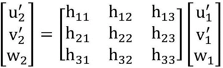
具体来说,单应性矩阵为3×3的矩阵,共9个参数。比如,单应性矩阵为:Specifically, the homography matrix is a 3×3 matrix with a total of 9 parameters. For example, the homography matrix is:

而由于求解过程中使用齐次坐标,具有尺度不变性,因此只需要求解8个 参数。However, due to the use of homogeneous coordinates in the solution process, it has scale invariance, so only 8 parameters are required to be solved.
假设一个标定点的图像坐标为(u1,v1),GPS坐标为(u2,v2),则存在齐次 关系:Assuming that the image coordinates of a calibration point are (u 1 , v 1 ) and the GPS coordinates are (u 2 , v 2 ), there is a homogeneous relationship:

根据该齐次关系,可以列出单应性转换关系式:According to this homogeneous relation, the homography transformation relation can be listed:
将上述单应性转换关系式中提出h33作为因子得到:Taking h 33 as a factor in the above homography transformation relation, we get:

进而推导得到图像坐标为(u1,v1)和GPS坐标为(u2,v2)的展开关系式:Then, the expansion relation of image coordinates (u 1 , v 1 ) and GPS coordinates (u 2 , v 2 ) is derived:

将上述展开关系式进行化简得到:Simplify the above expansion relationship to get:
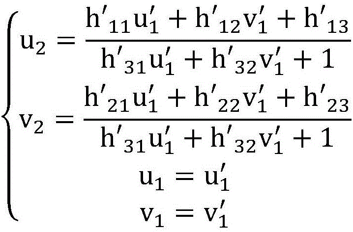
将(u1,v1)代入到(u2,v2)中得到:Substitute (u 1 , v 1 ) into (u 2 , v 2 ) to get:

可见,每个标定点可以列出2个算式,四个标定点可以列出8个算式,即可 以求解8个未知数,这样,得求解得到了单应性矩阵。It can be seen that each calibration point can list 2 equations, and four calibration points can list 8 equations, that is, 8 unknowns can be solved. In this way, the homography matrix can be obtained by solving.
一种情况下,可以在所述标定图像中设定多个标定点,将所述多个标定点 中每4个不共线的标定点组合成一个标定点组。In one case, multiple calibration points may be set in the calibration image, and every four non-collinear calibration points in the multiple calibration points are combined into a calibration point group.
举例来说,在标定图像中设定标定点时,可以设定覆盖全面且均匀的标定 点。如图2所示,可以设定9个标定点,将这9个标定点中每4个不共线的点组合 成一个标定点组,也就是得到了C9 4个标定点组。每个标定点组求解一个单应性 矩阵,也就得到了C9 4个单应性矩阵。For example, when the calibration points are set in the calibration image, a comprehensive and uniform calibration point can be set. As shown in Figure 2, 9 calibration points can be set, and every 4 non-collinear points in the 9 calibration points are combined into a calibration point group, that is, C 9 4 calibration point groups are obtained. One homography matrix is solved for each calibration point group, and C 9 4 homography matrices are obtained.
如上所述,标定点既存在于标定图像中,也存在于监控图像中,因而可以 在监控图像中,确定跟踪目标与各标定点组的图像距离。一种情况下,该图像 距离可以为欧氏距离,或者也可以为马氏距离,具体不做限定。本实施方式中 所说的预设距离条件可以为:与跟踪目标的图像距离最小,或者为与跟踪目标 的图像距离次小,或者为与跟踪目标的图像距离小于预设阈值,具体不做限定。As mentioned above, the calibration points exist both in the calibration image and in the monitoring image, so the image distance between the tracking target and each calibration point group can be determined in the monitoring image. In one case, the image distance may be the Euclidean distance, or may also be the Mahalanobis distance, which is not specifically limited. The preset distance condition mentioned in this embodiment may be: the image distance from the tracking target is the smallest, or the image distance from the tracking target is the second smallest, or the image distance from the tracking target is less than a preset threshold, which is not specifically limited .
举例来说,标定点组与跟踪目标的图像距离可以为:标定点组中各标定点 与跟踪目标中心点的距离之和。参考图3,跟踪目标中心点位置为A,标定点组 1中包括4个标定点,这4个标定点的位置分别为B、C、D、E,则标定点组1与 跟踪目标的图像距离可以为:A与B之间的距离+A与C之间的距离+A与D之间 的距离+A与E之间的距离。For example, the image distance between the calibration point group and the tracking target may be: the sum of the distances between each calibration point in the calibration point group and the center point of the tracking target. Referring to Figure 3, the position of the center point of the tracking target is A, and the calibration point group 1 includes 4 calibration points. The positions of these 4 calibration points are B, C, D, and E respectively. Then the image of the calibration point group 1 and the tracking target The distance may be: distance between A and B+distance between A and C+distance between A and D+distance between A and E.
图3中存在9个标定点、C9 4个标定点组,假设预设距离条件为:与跟踪目标 的图像距离最小,则在图3中选择出的标定点组为标定点组1。There are 9 calibration points and C 9 4 calibration point groups in FIG. 3 . Assuming that the preset distance condition is: the image distance from the tracking target is the smallest, the calibration point group selected in FIG. 3 is the calibration point group 1 .
如上所述,预先基于每个标定点组求解得到一个单应性矩阵,该单应性矩 阵即可以理解为图像坐标系与GPS坐标系之间的映射关系。因此,基于目标标 定点组的单应性矩阵,可以将跟踪目标在监控图像中的坐标转换为GPS坐标。As described above, a homography matrix is obtained by solving based on each calibration point group in advance, and the homography matrix can be understood as the mapping relationship between the image coordinate system and the GPS coordinate system. Therefore, based on the homography matrix of the target calibration point group, the coordinates of the tracking target in the monitoring image can be converted into GPS coordinates.
另一种实施方式中,S101可以包括:获取球机拍摄跟踪目标时的PT (Pan/Tilt,云台左右/上下移动)坐标,作为第一P坐标和第一T坐标;基于所 述第一P坐标,确定所述跟踪目标与指定方向的水平夹角;基于所述第一T坐标 以及所述球机的高度,计算所述跟踪目标与所述球机的水平距离;根据所述水 平夹角和所述水平距离,通过三角函数计算所述跟踪目标与所述球机的经线方 向距离和纬线方向距离;基于所述球机的经纬度以及所述经线方向距离和纬线 方向距离,计算所述跟踪目标的GPS坐标。In another embodiment, S101 may include: acquiring the PT (Pan/Tilt, pan/tilt left/right movement) coordinates when the dome camera shoots the tracking target, as the first P coordinate and the first T coordinate; based on the first P coordinate, determine the horizontal angle between the tracking target and the specified direction; based on the first T coordinate and the height of the dome camera, calculate the horizontal distance between the tracking target and the dome camera; angle and the horizontal distance, calculate the distance in the longitude direction and the latitude direction of the tracking target and the ball camera through trigonometric functions; Track the GPS coordinates of the target.
本实施方式中,拍摄跟踪目标的摄像机为球机,可以将球机拍摄跟踪目标 时的PT坐标转换为跟踪目标的GPS坐标。In this embodiment, the camera that shoots the tracking target is a dome camera, and the PT coordinates when the dome camera shoots the tracking target can be converted into the GPS coordinates of the tracking target.
本实施方式中,可以通过球机的电子罗盘,获取球机指向指定方向时的球 机的P坐标,作为第二P坐标;计算所述第一P坐标与所述第二P坐标之差,作为 所述跟踪目标与所述指定方向的水平夹角。In this embodiment, the P-coordinate of the dome camera when the dome camera points to a specified direction can be obtained through the electronic compass of the dome machine, as the second P-coordinate; the difference between the first P-coordinate and the second P-coordinate is calculated, as the horizontal included angle between the tracking target and the specified direction.
通过球机的电子罗盘,可以获取球机指向正北、正南、正东、正西等方向 时的球机的P坐标,为了区分描述,将该P坐标称为第二P坐标。第一P坐标与第 二P坐标之差,即为跟踪目标与指定方向的水平夹角。Through the electronic compass of the dome camera, you can obtain the P coordinate of the dome camera when the dome camera points to the north, south, east, west and other directions. In order to distinguish the description, the P coordinate is called the second P coordinate. The difference between the first P coordinate and the second P coordinate is the horizontal angle between the tracking target and the specified direction.
本实施方式中,可以计算第一T坐标的正切值与所述球机的高度的乘积, 作为跟踪目标与所述球机的水平距离。参考图4可知,tanT*h=L,h表示球机的 高度,L表示跟踪目标与球机的水平距离。水平距离也就是假设球机与跟踪目 标高度相同的情况下,球机与跟踪目标的距离。In this embodiment, the product of the tangent value of the first T coordinate and the height of the dome camera can be calculated as the horizontal distance between the tracking target and the dome camera. Referring to Figure 4, tanT*h=L, h represents the height of the dome camera, and L represents the horizontal distance between the tracking target and the dome camera. The horizontal distance is the distance between the dome camera and the tracking target, assuming that the height of the dome camera and the tracking target is the same.
如果该指定方向为正北,则可以计算所述水平夹角的正弦值与所述水平距 离的乘积,作为所述跟踪目标与所述球机的经线方向距离;计算所述水平夹角 的余弦值与所述水平距离的乘积,作为所述跟踪目标与所述球机的纬线方向距 离。If the specified direction is true north, the product of the sine value of the horizontal angle and the horizontal distance can be calculated as the meridian distance between the tracking target and the dome camera; calculate the cosine of the horizontal angle The product of the value and the horizontal distance is used as the latitude direction distance between the tracking target and the dome camera.
参考图5,图5为球机的俯视图,图5中未体现球机的高度,由图5可知, L*sinθ=Llon,L*cosθ=Llat,L表示上述计算得到的水平距离,θ表示上述得到的 跟踪目标与正北方向的水平夹角,Llon表示跟踪目标与球机的经线方向距离, Llat表示跟踪目标与球机的纬线方向距离。Referring to Figure 5, Figure 5 is a top view of the dome camera, the height of the dome camera is not reflected in Figure 5, it can be seen from Figure 5 that L*sinθ=L lon , L*cosθ=L lat , L represents the horizontal distance calculated above, θ represents the horizontal angle between the tracking target and the true north direction obtained above, L lon represents the distance between the tracking target and the dome camera in the longitude direction, and L lat represents the distance between the tracking target and the dome camera in the latitude direction.
如果该指定方向为指定方向为正东,则可以计算所述水平夹角的余弦值与 所述水平距离的乘积,作为所述跟踪目标与所述球机的经线方向距离;计算所 述水平夹角的正弦值与所述水平距离的乘积,作为所述跟踪目标与所述球机的 纬线方向距离。If the specified direction is due east, the product of the cosine value of the horizontal included angle and the horizontal distance can be calculated as the meridian distance between the tracking target and the dome camera; The product of the sine value of the angle and the horizontal distance is taken as the distance between the tracking target and the ball camera in the weft direction.
这种情况下,跟踪目标与正东方向的水平夹角为图5中的α,L*sinα=Llon, L*cosα=Llat。In this case, the horizontal included angle between the tracking target and the due east direction is α in FIG. 5 , L*sinα=L lon , L*cosα=L lat .
或者,该指定方向为正西或者正南,具体计算过程类似,不再赘述。Alternatively, the designated direction is due west or due south, and the specific calculation process is similar, which is not repeated here.
球机通常具有GPS定位装置,可以基于该GPS定位装置得到球机的GPS坐 标,GPS坐标中包括经纬度,这样,得到了球机的经纬度以及球机与跟踪目标 的经线方向距离和纬线方向距离,便可以计算得到跟踪目标的经纬度,也就得 到了跟踪目标的GPS坐标。The dome camera usually has a GPS positioning device, and the GPS coordinates of the dome camera can be obtained based on the GPS positioning device, and the GPS coordinates include the latitude and longitude. The latitude and longitude of the tracking target can be calculated, and the GPS coordinates of the tracking target can be obtained.
S102:针对预先划分的每个区域,基于获取到的每个跟踪目标的GPS坐标, 统计位于该区域的跟踪目标的数量。S102: For each pre-divided area, based on the acquired GPS coordinates of each tracking target, count the number of tracking targets located in the area.
预先将服务器管理下的各摄像机覆盖的监控区域进行划分。比如,可以按 照行政区域进行划分,或者,可以按照地理位置进行划分,具体划分方式不做 限定。举例来说,假设服务器管理下的各摄像机覆盖了A城市,A城市包括6个 行政区域,则可以针对这6个行政区域中的每个行政区域,基于获取到的每个 跟踪目标的GPS坐标,统计位于该行政区域的跟踪目标的数量。The monitoring area covered by each camera under the server management is divided in advance. For example, it can be divided according to administrative regions, or it can be divided according to geographical location, and the specific division method is not limited. For example, assuming that the cameras managed by the server cover city A, and city A includes 6 administrative regions, then for each of the 6 administrative regions, the GPS coordinates of each tracking target can be obtained based on the obtained GPS coordinates. , and count the number of tracking targets located in the administrative area.
一种实施方式中,还可以获取每个跟踪目标的GPS坐标对应的时间戳;这 种情况下,S102可以包括:基于获取到的每个跟踪目标的GPS坐标及对应的时 间戳,统计每个时间段内位于该区域的跟踪目标的数量。In one embodiment, the time stamp corresponding to the GPS coordinates of each tracking target may also be obtained; in this case, S102 may include: based on the obtained GPS coordinates and corresponding time stamps of each tracking target, count each tracking target. The number of tracked objects located in the area during the time period.
如上所述,服务器可以接收每台摄像机发送的数据包,数据包中包括每个 跟踪目标的GPS坐标;一种情况下,数据包中还可以包括每个跟踪目标的GPS 坐标对应的时间戳。这样,对跟踪目标进行统筹时,增加了时间维度,对于一 个区域来说,可以统计其在各时间段内的跟踪目标的数量。As mentioned above, the server can receive data packets sent by each camera, and the data packets include the GPS coordinates of each tracking target; in one case, the data packets can also include a timestamp corresponding to the GPS coordinates of each tracking target. In this way, when coordinating the tracking targets, the time dimension is added, and for an area, the number of tracking targets in each time period can be counted.
S103:根据每个区域的跟踪目标的数量,生成跟踪目标的热度图。S103: Generate a heat map of the tracking targets according to the number of tracking targets in each area.
一种情况下,参考图6,热度图可以包括每个区域的跟踪目标的数量。图6 中,区域A的跟踪目标的数量为800,区域B的跟踪目标的数量为60,区域C的 跟踪目标的数量为200。图6仅为举例说明,并不对本发明实施例构成限定。In one case, referring to Figure 6, the heat map may include the number of tracked targets per region. In Figure 6, the number of tracking targets in area A is 800, the number of tracking targets in area B is 60, and the number of tracking targets in area C is 200. FIG. 6 is for illustration only, and does not limit the embodiment of the present invention.
上述一种实施方式中,获取每个跟踪目标的GPS坐标对应的时间戳,并统 计每个时间段内位于每个区域的跟踪目标的数量;这种情况下,S103可以包括: 根据每个区域在每个时间段内的跟踪目标的数量,生成跟踪目标的热度图。In the above-mentioned one embodiment, the time stamp corresponding to the GPS coordinates of each tracking target is obtained, and the number of tracking targets located in each area in each time period is counted; in this case, S103 may include: According to each area The number of tracked targets in each time period, and a heatmap of tracked targets is generated.
这种实施方式中,参考图7,热度图中可以包括每个区域在每个时间段内 的跟踪目标的数量。图7中,区域A在时间段1内的跟踪目标的数量为800,在时 间段2内的跟踪目标的数量为750,在时间段3内的跟踪目标的数量为850;区域 B在时间段1内的跟踪目标的数量为65,在时间段2内的跟踪目标的数量为70, 在时间段3内的跟踪目标的数量为75;区域C在时间段1内的跟踪目标的数量为 160,在时间段2内的跟踪目标的数量为190,在时间段3内的跟踪目标的数量为 185。图7仅为举例说明,并不对本发明实施例构成限定。In this embodiment, referring to FIG. 7 , the heat map may include the number of tracked targets for each region in each time period. In Figure 7, the number of tracking targets in area A in time period 1 is 800, the number of tracking targets in time period 2 is 750, and the number of tracking targets in time period 3 is 850; The number of tracking targets in 1 is 65, the number of tracking targets in time period 2 is 70, the number of tracking targets in time period 3 is 75; the number of tracking targets in area C in time period 1 is 160 , the number of tracking targets in time period 2 is 190, and the number of tracking targets in time period 3 is 185. FIG. 7 is for illustration only, and does not limit the embodiment of the present invention.
另一种实施方式中,还可以获取每个跟踪目标的属性信息;这样S103可以 包括:生成跟踪目标的热力图,所述热力图中包括每个区域的跟踪目标的数量、 以及每个跟踪目标的属性信息。In another embodiment, attribute information of each tracking target can also be obtained; in this way, S103 may include: generating a heat map of the tracking target, the heat map including the number of tracking targets in each area and each tracking target. attribute information.
举例来说,如果跟踪目标为车辆目标,则属性信息可以为车牌号或者包括 车辆目标的图像,如果跟踪目标为人体目标,则属性信息可以为人员名称、ID 号,或者人脸图像,等等,属性信息的具体内容不做限定。For example, if the tracking target is a vehicle target, the attribute information can be the license plate number or an image including the vehicle target. If the tracking target is a human target, the attribute information can be the person's name, ID number, or face image, etc. , the specific content of the attribute information is not limited.
一种情况下,跟踪目标的属性信息可以叠加展示在热力图中。或者,另一 种情况下,热力图可以包括两部分,一部分展示每个区域的跟踪目标的数量, 另一部分可以展示每个跟踪目标的属性信息,具体展示方式不做限定。In one case, the attribute information of the tracking target can be superimposed on the heat map. Or, in another case, the heat map can include two parts, one part shows the number of tracking targets in each area, and the other part can show the attribute information of each tracking target, and the specific display method is not limited.
一种实施方式中,可以根据预先确定的GPS坐标系与全景图像坐标系之间 的转换关系,将获取到的每个跟踪目标的GPS坐标转换为全景图像中的坐标; 所述全景图像中包括每个区域;基于转换得到的全景图像中的坐标,在预先获 取的全景图像中叠加展示每个跟踪目标。In one embodiment, the obtained GPS coordinates of each tracking target can be converted into coordinates in the panoramic image according to the predetermined conversion relationship between the GPS coordinate system and the panoramic image coordinate system; the panoramic image includes: Each area; based on the coordinates in the transformed panoramic image, superimpose each tracking target in the pre-acquired panoramic image.
该全景图像可以为包括每个区域的地图,或者可以为覆盖每个区域的全景 相机采集的图像,或者可以为将每个区域中的摄像机采集的监控图像进行拼接 得到的图像,具体不做限定。举例来说,可以通过一台全景摄像机采集得到该 全景图像;或者,也可以通过服务器管理下的各台摄像机采集得到各个区域的 监控图像,将这些监控图像拼接得到该全景图像。The panoramic image may be a map including each area, or may be an image collected by a panoramic camera covering each area, or may be an image obtained by splicing monitoring images collected by cameras in each area, which is not specifically limited . For example, the panoramic image can be acquired by a panoramic camera; alternatively, the surveillance images of each area can be acquired by each camera under the management of the server, and the panoramic image can be obtained by splicing these surveillance images.
预先标定得到GPS坐标第与该全景图像坐标系之间的转换关系,这样,便 可以将跟踪目标的GPS坐标转换为全景图像中的坐标。比如,假设将跟踪目标 A的GPS坐标转换得到全景图像中的坐标(X1,Y1),则在全景图像中的坐标 (X1,Y1)处展示跟踪目标A。The conversion relationship between the GPS coordinates and the panoramic image coordinate system is obtained by pre-calibration, so that the GPS coordinates of the tracking target can be converted into coordinates in the panoramic image. For example, if the GPS coordinates of the tracking target A are converted to obtain the coordinates (X1, Y1) in the panoramic image, then the tracking target A is displayed at the coordinates (X1, Y1) in the panoramic image.
比如,可以在全景图像中的坐标(X1,Y1)处展示跟踪目标A的标识。或 者,上述一种实施方式中,获取每个跟踪目标的属性信息,这种情况下,可以 在全景图像中的坐标(X1,Y1)处展示跟踪目标A的属性信息。For example, the identification of the tracking target A may be displayed at the coordinates (X1, Y1) in the panoramic image. Alternatively, in the above-mentioned one embodiment, the attribute information of each tracking target is obtained, in this case, the attribute information of the tracking target A may be displayed at the coordinates (X1, Y1) in the panoramic image.
一种实施方式中,S103可以包括:针对预先划分的每个区域,根据位于该 区域的跟踪目标数量,确定该区域对应的颜色;生成跟踪目标的热度图,所述 热度图中包括每个区域的跟踪目标的数量,其中,每个区域跟踪目标的数量以 该区域对应的颜色进行展示。In one embodiment, S103 may include: for each pre-divided area, determining the color corresponding to the area according to the number of tracking targets located in the area; generating a heat map of the tracking target, the heat map including each area The number of tracking targets in each area is displayed in the color corresponding to the area.
举例来说,可以将跟踪目标数量划分等级,比如,0-50为1级,51-100为2 级,101-150为3级……等等,不再一一列举。可以设定各等级对应的颜色,比 如,1级对应的颜色为蓝色,2级对应的颜色为绿色,3级对应的颜色为黄色, 等等。可以根据用户的选择或者实际需求进行等级的划分及颜色的设定。For example, the number of tracking targets can be divided into levels, for example, 0-50 is level 1, 51-100 is level 2, 101-150 is level 3, etc., and will not be listed one by one. The color corresponding to each level can be set, for example, the color corresponding to level 1 is blue, the color corresponding to level 2 is green, the color corresponding to level 3 is yellow, and so on. The classification of grades and the setting of colors can be carried out according to the user's choice or actual needs.
一种情况下,可以将跟踪目标数量较多的区域可以对应较醒目的颜色,比 如红色,以提醒相关人员引起注意。In one case, an area with a large number of tracking targets can be corresponding to a more eye-catching color, such as red, to remind relevant personnel to pay attention.
一种实施方式中,在S103之后还可以包括:若位于该区域的跟踪目标的数 量大于第一预设阈值,则将监控该区域的摄像机的以下任意一种或多种参数调 大:分辨率、比特率、帧率、编码率。In an embodiment, after S103, it may further include: if the number of tracking targets located in the area is greater than the first preset threshold, then increasing any one or more of the following parameters of the camera monitoring the area: resolution , bit rate, frame rate, encoding rate.
本实施方式中,如果某区域中跟踪目标数量较多,则可以将监控该区域的 摄像机的分辨率、比特率、帧率、编码率等参数调大,以提高对该区域的监控 力度,获取到该区域的细节信息。In this implementation manner, if there are a large number of tracking targets in a certain area, parameters such as the resolution, bit rate, frame rate, and encoding rate of the cameras monitoring the area can be increased to improve the monitoring strength of the area, and obtain to the details of this area.
一种实施方式中,在S103之后还可以包括:若位于该区域的跟踪目标的数 量小于第二预设阈值,则将监控该区域的摄像机的以下任意一种或多种参数调 小:分辨率、比特率、帧率、编码率。In an embodiment, after S103, it may further include: if the number of tracking targets located in the area is less than the second preset threshold, reducing any one or more of the following parameters of the camera monitoring the area: resolution: , bit rate, frame rate, encoding rate.
第二预设阈值小于第一预设阈值。本实施方式中,如果某区域中跟踪目标 数量较少,则可以将监控该区域的摄像机的分辨率、比特率、帧率、编码率等 参数调小,以减少对该区域的监控力度,节省摄像机的资源消耗。The second preset threshold is smaller than the first preset threshold. In this embodiment, if the number of tracking targets in a certain area is small, the resolution, bit rate, frame rate, encoding rate and other parameters of the camera monitoring the area can be reduced to reduce the monitoring intensity of the area and save energy The resource consumption of the camera.
一种实施方式中,在S103之后还可以包括:若位于该区域的跟踪目标的数 量大于第三预设阈值,则检测该区域中的摄像机采集的监控图像,判断是否发 生异常事件;如果发生异常事件,则输出报警信息。In one embodiment, after S103, it may further include: if the number of tracking targets located in the area is greater than the third preset threshold, detecting the monitoring images collected by the cameras in the area, and judging whether an abnormal event occurs; if an abnormal event occurs event, then output alarm information.
第三预设阈值与第一预设阈值可以相同,也可以不同,具体数值不做限定。 可以理解,如果某区域中跟踪目标数量较多,则表示该区域可能发生了交通事 故、或者交通拥堵、或者群体性事件等异常事件。本实施方式中,如果某区域 中跟踪目标数量较多,则检测该区域中的摄像机采集的监控图像,判断是否发 生异常事件,如果发生异常事件,输出报警信息。The third preset threshold and the first preset threshold may be the same or different, and the specific value is not limited. It can be understood that if there are a large number of tracking targets in an area, it means that abnormal events such as traffic accidents, traffic congestion, or mass events may have occurred in this area. In this embodiment, if there are a large number of tracking targets in a certain area, the monitoring images collected by the cameras in the area are detected to determine whether an abnormal event occurs, and if an abnormal event occurs, an alarm message is output.
举例来说,可以采用显示文字的形式输出报警信息,或者可以采用语音播 报的形式输出报警信息,或者可以采集灯光闪烁的形式输出报警信息。输出报 警信息的具体形式不做限定。For example, the alarm information can be output in the form of displayed text, or the alarm information can be output in the form of voice broadcast, or the alarm information can be output in the form of collecting lights flashing. The specific form of outputting alarm information is not limited.
一种实施方式中,在S103之后还可以包括:若位于该区域的跟踪目标的数 量大于第四预设阈值,则控制该区域对应的全景相机针对该区域进行图像采集; 获取所述全景相机针对该区域采集的全景图像。In one embodiment, after S103, it may further include: if the number of tracking targets located in the area is greater than the fourth preset threshold, controlling the panoramic camera corresponding to the area to perform image capture for the area; Panoramic image captured in this area.
第四预设阈值与第三预设阈值及第一预设阈值可以相同,也可以不同,具 体数值不做限定。如果某区域中跟踪目标数量较多,则表示该区域可能发生了 交通事故、或者交通拥堵、或者群体性事件等异常事件。本实施方式中,可以 在每个区域中设置一台或多台全景相机,如果某区域中跟踪目标数量较多,则 控制该区域对应的全景相机采集该区域的全景图像,通过该全景图像可以及时 了解该区域是否发生了异常事件,并及时了解异常事件的相关情况,以便进行 后续处理。The fourth preset threshold may be the same as the third preset threshold and the first preset threshold, or may be different, and the specific values are not limited. If there are a large number of tracking targets in an area, it means that abnormal events such as traffic accidents, traffic congestion, or mass events may have occurred in this area. In this embodiment, one or more panoramic cameras can be set in each area. If there are many tracking targets in a certain area, the panoramic camera corresponding to the area is controlled to collect a panoramic image of the area. Know whether an abnormal event has occurred in the area in time, and know the relevant situation of the abnormal event in time for follow-up processing.
上述一种实施方式中,拍摄跟踪目标的摄像机为球机,将球机拍摄跟踪目 标时的PT坐标转换为跟踪目标的GPS坐标。In the above-mentioned embodiment, the camera that shoots the tracking target is a dome camera, and the PT coordinates when the dome camera shoots the tracking target are converted into GPS coordinates of the tracking target.
这种实施方式中,获取球机拍摄跟踪目标时的PT坐标,作为第一P坐标和 第一T坐标,可以包括:In this embodiment, obtain the PT coordinates when the ball camera shoots the tracking target, as the first P coordinates and the first T coordinates, can include:
获取跟踪目标在球机拍摄图像中的图像坐标;根据所述图像坐标、以及所 述球机拍摄所述跟踪目标时的视场角,确定所述球机正对所述跟踪目标时的PT 坐标,作为第一P坐标和第一T坐标。Obtain the image coordinates of the tracking target in the image captured by the dome camera; determine the PT coordinates when the dome camera is facing the tracking target according to the image coordinates and the field of view angle when the dome camera shoots the tracking target , as the first P coordinate and the first T coordinate.
假设跟踪目标在球机拍摄图像中的图像坐标为(X,Y),则可以利用以下 算式转换得到第一P坐标和第一T坐标:Assuming that the image coordinates of the tracking target in the image captured by the dome camera are (X, Y), the first P coordinate and the first T coordinate can be obtained by converting the following formula:
Pan_tar=Pan_cur+arctan((2*X/L1-1)*tan(θ1/2));Pan_tar=Pan_cur+arctan((2*X/L 1 -1)*tan(θ 1 /2));
Tilt_tar=Tilt_cur+arctan((2*Y/L2-1)*tan(θ2/2));Tilt_tar=Tilt_cur+arctan((2*Y/L 2 -1)*tan(θ 2 /2));
其中,Pan_tar表示第一P坐标,Tilt_tar表示第一T坐标,Pan_cur表示当前 球机在PT坐标系中的水平方向角度,Tilt_cur表示当前球机在PT坐标系中的垂 直方向角度,(Pan_cur,Tilt_cur)对应当前图像中心位置,L1表示图像横向的 总像素数,L2表示图像纵向的总像素数,θ1表示为当前图像所对应的水平视场 角,θ2表示为当前图像所对应的垂直视场角;XY坐标系以图像左上角为原点, 以像素为单位。Among them, Pan_tar represents the first P coordinate, Tilt_tar represents the first T coordinate, Pan_cur represents the horizontal angle of the current dome camera in the PT coordinate system, Tilt_cur represents the vertical direction angle of the current dome camera in the PT coordinate system, (Pan_cur, Tilt_cur ) corresponds to the center position of the current image, L 1 represents the total number of pixels in the horizontal direction of the image, L 2 represents the total number of pixels in the vertical direction of the image, θ 1 represents the horizontal field of view corresponding to the current image, and θ 2 represents the corresponding horizontal field angle of the current image. Vertical field of view; the XY coordinate system takes the upper left corner of the image as the origin, in pixels.
参考图4及图5可知,若球机正对跟踪目标,则得到的跟踪目标的GPS坐标 更准确。而应用本实施方式得到的第一P坐标和第一T坐标为球机正对跟踪目标 时的PT坐标,因此,利用本实施方式,可以得到更准确的GPS坐标。Referring to Figure 4 and Figure 5, it can be known that if the dome camera is facing the tracking target, the GPS coordinates of the tracking target obtained are more accurate. The first P coordinate and the first T coordinate obtained by applying this embodiment are the PT coordinates when the dome camera is facing the tracking target. Therefore, by using this embodiment, more accurate GPS coordinates can be obtained.
另外,这种实施方式中,将所述第一P坐标和第一T坐标发送至所述球机; 获取所述球机根据所述第一P坐标和第一T坐标调整拍摄角度后采集的监控图 像。In addition, in this embodiment, the first P-coordinate and the first T-coordinate are sent to the dome camera; and the dome camera is acquired after adjusting the shooting angle according to the first P-coordinate and the first T-coordinate. Monitor images.
如上所述,第一P坐标和第一T坐标为球机正对跟踪目标时的PT坐标,将 第一P坐标和第一T坐标发送至球机,球机根据该第一P坐标和第一T坐标,对 自身拍摄角度进行调整,并在调整后针对跟踪目标采集监控图像,将该监控图 像发送至服务器。这样,服务器可以获取到正对该跟踪目标的图像,方便相关 人员基于该图像了解到相关信息。As mentioned above, the first P coordinate and the first T coordinate are the PT coordinates when the ball camera is facing the tracking target, and the first P coordinate and the first T coordinate are sent to the ball camera. A T coordinate is used to adjust its own shooting angle, and after the adjustment, a monitoring image is collected for the tracking target, and the monitoring image is sent to the server. In this way, the server can obtain the image of the tracking target, which is convenient for relevant personnel to learn relevant information based on the image.
比如,假设跟踪目标为肇事逃逸的车辆目标,应用本实施方式,球机可以 正对该车辆目标采集到包含该车辆目标车牌的监控图像,将该监控图像发送至 服务器,相关人员可以得到肇事逃逸车辆的车牌信息。For example, assuming that the tracking target is a hit-and-run vehicle target, applying this embodiment, the dome camera can collect a monitoring image containing the vehicle target's license plate, and send the monitoring image to the server, and relevant personnel can obtain the hit-and-run information. The license plate information of the vehicle.
本发明实施例中,获取每个跟踪目标的GPS坐标;针对预先划分的每个区 域,基于获取到的每个跟踪目标的GPS坐标,统计位于该区域的跟踪目标的数 量;根据每个区域的跟踪目标的数量,生成跟踪目标的热度图。可见,本方案 中,由一台设备基于各跟踪目标的GPS坐标,生成热度图,该热度图可以展现 各个区域的跟踪目标的数量,实现了对跟踪目标的统筹。In the embodiment of the present invention, the GPS coordinates of each tracking target are obtained; for each pre-divided area, the number of tracking targets located in the area is counted based on the obtained GPS coordinates of each tracking target; The number of tracked targets, and a heatmap of tracked targets is generated. It can be seen that, in this solution, a device generates a heat map based on the GPS coordinates of each tracking target, and the heat map can display the number of tracking targets in each area, realizing the overall planning of the tracking targets.
与上述方法实施例相对应,本发明实施例还提供了一种基于GPS坐标的目 标统筹装置,如图8所示,包括:Corresponding to the above-mentioned method embodiment, the embodiment of the present invention also provides a target coordinating device based on GPS coordinates, as shown in Figure 8, including:
第一获取模块801,用于获取每个跟踪目标的GPS坐标;The
统计模块802,用于针对预先划分的每个区域,基于获取到的每个跟踪目 标的GPS坐标,统计位于该区域的跟踪目标的数量;
生成模块803,用于根据每个区域的跟踪目标的数量,生成跟踪目标的热 度图。The
作为一种实施方式,第一获取模块801具体用于:As an implementation manner, the first obtaining
接收每台摄像机发送的监控图像,识别所述监控图像中的跟踪目标,将所 述跟踪目标在所述监控图像坐标系中的坐标转换为GPS坐标;Receive the monitoring image sent by each camera, identify the tracking target in the monitoring image, and convert the coordinates of the tracking target in the monitoring image coordinate system into GPS coordinates;
或者,接收每台摄像机发送的数据包,所述数据包中包括每个跟踪目标的 GPS坐标。Alternatively, a data packet sent by each camera is received, and the data packet includes the GPS coordinates of each tracking target.
作为一种实施方式,第一获取模块801还用于:As an implementation manner, the first obtaining
在预先设定的各标定点组中,选择与所述跟踪目标的距离满足预设距离条 件的标定点组,作为目标标定点组;In each preset calibration point group, select the calibration point group whose distance from the tracking target satisfies the preset distance condition as the target calibration point group;
基于预先获取的、针对所述目标标定点组标定得到的单应性矩阵,将所述 跟踪目标在所述监控图像坐标系中的坐标转换为GPS坐标。Based on the homography matrix obtained in advance and calibrated for the target calibration point group, the coordinates of the tracking target in the monitoring image coordinate system are converted into GPS coordinates.
作为一种实施方式,第一获取模块801具体用于:As an implementation manner, the first obtaining
获取球机拍摄跟踪目标时的PT坐标,作为第一P坐标和第一T坐标;Obtain the PT coordinates when the dome camera shoots and track the target, as the first P coordinate and the first T coordinate;
基于所述第一P坐标,确定所述跟踪目标与指定方向的水平夹角;Based on the first P coordinate, determine the horizontal angle between the tracking target and the specified direction;
基于所述第一T坐标以及所述球机的高度,计算所述跟踪目标与所述球机 的水平距离;Based on the first T coordinate and the height of the ball machine, calculate the horizontal distance between the tracking target and the ball machine;
根据所述水平夹角和所述水平距离,通过三角函数计算所述跟踪目标与所 述球机的经线方向距离和纬线方向距离;According to the horizontal included angle and the horizontal distance, the distance in the warp direction and the weft direction distance of the tracking target and the ball camera are calculated by trigonometric function;
基于所述球机的经纬度以及所述经线方向距离和纬线方向距离,计算所述 跟踪目标的GPS坐标。Based on the longitude and latitude of the dome camera and the distance in the longitude and latitude directions, the GPS coordinates of the tracking target are calculated.
作为一种实施方式,所述装置还包括:As an embodiment, the device further includes:
第二获取模块(图中未示出),用于获取每个跟踪目标的GPS坐标对应的 时间戳;The second acquisition module (not shown in the figure) is used to acquire the time stamp corresponding to the GPS coordinates of each tracking target;
统计模块802具体用于:基于获取到的每个跟踪目标的GPS坐标及对应的 时间戳,统计每个时间段内位于该区域的跟踪目标的数量;
生成模块803具体用于:根据每个区域在每个时间段内的跟踪目标的数量, 生成跟踪目标的热度图。The
作为一种实施方式,所述装置还包括:As an embodiment, the device further includes:
第三获取模块(图中未示出),用于获取每个跟踪目标的属性信息;The third acquisition module (not shown in the figure) is used to acquire the attribute information of each tracking target;
生成模块803具体用于:生成跟踪目标的热力图,所述热力图中包括每个 区域的跟踪目标的数量、以及每个跟踪目标的属性信息。The
作为一种实施方式,所述装置还包括:转换模块和叠加模块(图中未示出),As an implementation manner, the device further includes: a conversion module and a superimposition module (not shown in the figure),
转换模块,用于根据预先确定的GPS坐标系与全景图像坐标系之间的转换 关系,将获取到的每个跟踪目标的GPS坐标转换为全景图像中的坐标;所述全 景图像中包括每个区域;The conversion module is used to convert the obtained GPS coordinates of each tracking target into coordinates in the panoramic image according to the conversion relationship between the predetermined GPS coordinate system and the panoramic image coordinate system; the panoramic image includes each area;
叠加模块,用于基于转换得到的全景图像中的坐标,在预先获取的全景图 像中叠加展示每个跟踪目标。The overlay module is used to overlay and display each tracking target in the pre-acquired panoramic image based on the coordinates in the transformed panoramic image.
作为一种实施方式,所述全景图像为:包括每个区域的地图,或者为覆盖 每个区域的全景相机采集的图像,或者为将每个区域中的摄像机采集的监控图 像进行拼接得到的图像。As an embodiment, the panoramic image is: a map including each area, or an image collected by a panoramic camera covering each area, or an image obtained by splicing surveillance images collected by cameras in each area .
作为一种实施方式,生成模块803具体用于:针对预先划分的每个区域, 根据位于该区域的跟踪目标数量,确定该区域对应的颜色;生成跟踪目标的热 度图,所述热度图中包括每个区域的跟踪目标的数量,其中,每个区域跟踪目 标的数量以该区域对应的颜色进行展示。As an embodiment, the
作为一种实施方式,所述装置还包括:As an embodiment, the device further includes:
调整模块(图中未示出),用于若位于该区域的跟踪目标的数量大于第一 预设阈值,则将监控该区域的摄像机的以下任意一种或多种参数调大:分辨率、 比特率、帧率、编码率;An adjustment module (not shown in the figure), configured to increase any one or more of the following parameters of the camera monitoring the area if the number of tracking targets located in the area is greater than the first preset threshold: resolution, Bit rate, frame rate, encoding rate;
和/或,and / or,
若位于该区域的跟踪目标的数量小于第二预设阈值,则将监控该区域的摄 像机的以下任意一种或多种参数调小:分辨率、比特率、帧率、编码率。If the number of tracking targets located in the area is less than the second preset threshold, any one or more of the following parameters of the camera monitoring the area will be reduced: resolution, bit rate, frame rate, encoding rate.
作为一种实施方式,所述装置还包括:As an embodiment, the device further includes:
输出模块(图中未示出),用于若位于该区域的跟踪目标的数量大于第三 预设阈值,则检测该区域中的摄像机采集的监控图像,判断是否发生异常事件; 如果发生异常事件,则输出报警信息。The output module (not shown in the figure) is used to detect the monitoring images collected by the cameras in the area if the number of tracking targets located in the area is greater than the third preset threshold, and determine whether an abnormal event occurs; if an abnormal event occurs , the alarm information will be output.
作为一种实施方式,所述装置还包括:As an embodiment, the device further includes:
控制模块(图中未示出),用于若位于该区域的跟踪目标的数量大于第四 预设阈值,则控制该区域对应的全景相机针对该区域进行图像采集;获取所述 全景相机针对该区域采集的全景图像。a control module (not shown in the figure), for if the number of tracking targets located in the area is greater than the fourth preset threshold, then control the panoramic camera corresponding to the area to perform image acquisition for the area; obtain the panoramic camera for the area Panoramic image of the area collected.
作为一种实施方式,第一获取模块801还用于获取跟踪目标在球机拍摄图 像中的图像坐标;根据所述图像坐标、以及所述球机拍摄所述跟踪目标时的视 场角,确定所述球机正对所述跟踪目标时的PT坐标,作为第一P坐标和第一T 坐标;As an embodiment, the
所述装置还包括:发送模块和第四获取模块(图中未示出),其中,The device further includes: a sending module and a fourth obtaining module (not shown in the figure), wherein,
发送模块,用于将所述第一P坐标和第一T坐标发送至所述球机;a sending module, configured to send the first P coordinate and the first T coordinate to the ball camera;
第四获取模块,用于获取所述球机根据所述第一P坐标和第一T坐标调整拍 摄角度后采集的监控图像。The fourth acquisition module is used to acquire the monitoring image collected after the dome camera adjusts the shooting angle according to the first P coordinate and the first T coordinate.
本发明实施例中,获取每个跟踪目标的GPS坐标;针对预先划分的每个区 域,基于获取到的每个跟踪目标的GPS坐标,统计位于该区域的跟踪目标的数 量;根据每个区域的跟踪目标的数量,生成跟踪目标的热度图。可见,本方案 中,由一台设备基于各跟踪目标的GPS坐标,生成热度图,该热度图可以展现 各个区域的跟踪目标的数量,实现了对跟踪目标的统筹。In the embodiment of the present invention, the GPS coordinates of each tracking target are obtained; for each pre-divided area, the number of tracking targets located in the area is counted based on the obtained GPS coordinates of each tracking target; The number of tracked targets, and a heatmap of tracked targets is generated. It can be seen that, in this solution, a device generates a heat map based on the GPS coordinates of each tracking target, and the heat map can display the number of tracking targets in each area, realizing the overall planning of the tracking targets.
本发明实施例还提供了一种电子设备,如图9所示,包括处理器901和存储 器902,An embodiment of the present invention also provides an electronic device, as shown in FIG. 9, comprising a
存储器902,用于存放计算机程序;a
处理器901,用于执行存储器902上所存放的程序时,实现上述任一种基于 GPS坐标的目标统筹方法。The
上述电子设备提到的存储器可以包括随机存取存储器(Random Access Memory,RAM),也可以包括非易失性存储器(Non-Volatile Memory,NVM), 例如至少一个磁盘存储器。可选的,存储器还可以是至少一个位于远离前述 处理器的存储装置。The memory mentioned in the above electronic device may include random access memory (Random Access Memory, RAM), and may also include non-volatile memory (Non-Volatile Memory, NVM), such as at least one disk memory. Optionally, the memory may also be at least one storage device located remote from the aforementioned processor.
上述的处理器可以是通用处理器,包括中央处理器(Central Processing Unit,CPU)、网络处理器(Network Processor,NP)等;还可以是数字信号处理器 (DigitalSignal Processing,DSP)、专用集成电路(Application Specific Integrated Circuit,ASIC)、现场可编程门阵列(Field-Programmable Gate Array,FPGA) 或者其他可编程逻辑器件、分立门或者晶体管逻辑器件、分立硬件组件。The above-mentioned processor may be a general-purpose processor, including a central processing unit (Central Processing Unit, CPU), a network processor (Network Processor, NP), etc.; it may also be a digital signal processor (Digital Signal Processing, DSP), an application-specific integrated circuit (Application Specific Integrated Circuit, ASIC), Field-Programmable Gate Array (Field-Programmable Gate Array, FPGA) or other programmable logic devices, discrete gate or transistor logic devices, discrete hardware components.
本发明实施例还提供一种计算机可读存储介质,所述计算机可读存储介质 内存储有计算机程序,所述计算机程序被处理器执行时实现上述任一种基于 GPS坐标的目标统筹方法。Embodiments of the present invention further provide a computer-readable storage medium, where a computer program is stored in the computer-readable storage medium, and when the computer program is executed by a processor, any one of the above-mentioned GPS coordinate-based target coordination methods is implemented.
需要说明的是,在本文中,诸如第一和第二等之类的关系术语仅仅用来将 一个实体或者操作与另一个实体或操作区分开来,而不一定要求或者暗示这些 实体或操作之间存在任何这种实际的关系或者顺序。而且,术语“包括”、“包 含”或者其任何其他变体意在涵盖非排他性的包含,从而使得包括一系列要素 的过程、方法、物品或者设备不仅包括那些要素,而且还包括没有明确列出的 其他要素,或者是还包括为这种过程、方法、物品或者设备所固有的要素。在 没有更多限制的情况下,由语句“包括一个……”限定的要素,并不排除在包括 所述要素的过程、方法、物品或者设备中还存在另外的相同要素。It should be noted that, in this document, relational terms such as first and second are only used to distinguish one entity or operation from another entity or operation, and do not necessarily require or imply any relationship between these entities or operations. any such actual relationship or sequence exists. Moreover, the terms "comprising", "comprising" or any other variation thereof are intended to encompass a non-exclusive inclusion such that a process, method, article or device that includes a list of elements includes not only those elements, but also includes not explicitly listed or other elements inherent to such a process, method, article or apparatus. Without further limitation, an element qualified by the phrase "comprising a..." does not preclude the presence of additional identical elements in a process, method, article or apparatus that includes the element.
本说明书中的各个实施例均采用相关的方式描述,各个实施例之间相同相 似的部分互相参见即可,每个实施例重点说明的都是与其他实施例的不同之处。 尤其,对于装置实施例、设备实施例、以及计算机可读存储介质实施例而言, 由于其基本相似于方法实施例,所以描述的比较简单,相关之处参见方法实施 例的部分说明即可。Each embodiment in this specification is described in a related manner, and the same and similar parts between the various embodiments can be referred to each other, and each embodiment focuses on the differences from other embodiments. Especially, for the apparatus embodiment, the device embodiment, and the computer-readable storage medium embodiment, since they are basically similar to the method embodiment, the description is relatively simple.
以上所述仅为本发明的较佳实施例而已,并非用于限定本发明的保护范围。 凡在本发明的精神和原则之内所作的任何修改、等同替换、改进等,均包含在 本发明的保护范围内。The above descriptions are only preferred embodiments of the present invention, and are not intended to limit the protection scope of the present invention. Any modification, equivalent replacement, improvement, etc. made within the spirit and principle of the present invention are all included in the protection scope of the present invention.
Claims (16)
Priority Applications (4)
| Application Number | Priority Date | Filing Date | Title |
|---|---|---|---|
| CN201811485122.9A CN111290001A (en) | 2018-12-06 | 2018-12-06 | Target overall planning method, device and equipment based on GPS coordinates |
| PCT/CN2019/119244 WO2020114232A1 (en) | 2018-12-06 | 2019-11-18 | Gps coordinates-based target overall planning method and camera |
| US17/287,659 US11985428B2 (en) | 2018-12-06 | 2019-11-18 | GPS coordinates-based target overall planning method and camera |
| EP19892928.3A EP3849176A4 (en) | 2018-12-06 | 2019-11-18 | Gps coordinates-based target overall planning method and camera |
Applications Claiming Priority (1)
| Application Number | Priority Date | Filing Date | Title |
|---|---|---|---|
| CN201811485122.9A CN111290001A (en) | 2018-12-06 | 2018-12-06 | Target overall planning method, device and equipment based on GPS coordinates |
Publications (1)
| Publication Number | Publication Date |
|---|---|
| CN111290001A true CN111290001A (en) | 2020-06-16 |
Family
ID=70973806
Family Applications (1)
| Application Number | Title | Priority Date | Filing Date |
|---|---|---|---|
| CN201811485122.9A Pending CN111290001A (en) | 2018-12-06 | 2018-12-06 | Target overall planning method, device and equipment based on GPS coordinates |
Country Status (4)
| Country | Link |
|---|---|
| US (1) | US11985428B2 (en) |
| EP (1) | EP3849176A4 (en) |
| CN (1) | CN111290001A (en) |
| WO (1) | WO2020114232A1 (en) |
Cited By (4)
| Publication number | Priority date | Publication date | Assignee | Title |
|---|---|---|---|---|
| CN111741305A (en) * | 2020-08-27 | 2020-10-02 | 科大讯飞(苏州)科技有限公司 | Video coding method and device, electronic equipment and readable storage medium |
| CN112489438A (en) * | 2020-11-19 | 2021-03-12 | 公安部第三研究所 | Radar and dome camera linkage system and method for realizing mobile target data calibration |
| WO2022062862A1 (en) * | 2020-09-25 | 2022-03-31 | 杭州海康威视数字技术股份有限公司 | Method and apparatus for determining heat data of global region, and storage medium |
| CN114461738A (en) * | 2021-12-22 | 2022-05-10 | 浙江大华技术股份有限公司 | Method and device for generating data thermodynamic diagram and computer readable storage medium |
Families Citing this family (1)
| Publication number | Priority date | Publication date | Assignee | Title |
|---|---|---|---|---|
| CN111862211B (en) * | 2020-07-22 | 2023-10-27 | 杭州海康威视数字技术股份有限公司 | Positioning methods, devices, systems, storage media and computer equipment |
Citations (8)
| Publication number | Priority date | Publication date | Assignee | Title |
|---|---|---|---|---|
| EP0603908A2 (en) * | 1992-12-25 | 1994-06-29 | Dainippon Screen Mfg. Co., Ltd. | Method of and apparatus for converting image signals |
| CN101320427A (en) * | 2008-07-01 | 2008-12-10 | 北京中星微电子有限公司 | Video monitoring method and system with auxiliary objective monitoring function |
| CN103578109A (en) * | 2013-11-08 | 2014-02-12 | 中安消技术有限公司 | Method and device for monitoring camera distance measurement |
| CN105072414A (en) * | 2015-08-19 | 2015-11-18 | 浙江宇视科技有限公司 | A method and system for target detection and tracking |
| CN105407278A (en) * | 2015-11-10 | 2016-03-16 | 北京天睿空间科技股份有限公司 | Panoramic video traffic situation monitoring system and method |
| CN106708955A (en) * | 2016-11-29 | 2017-05-24 | 浙江宇视科技有限公司 | Thermodynamic diagram generation method and equipment |
| CN107578368A (en) * | 2017-08-31 | 2018-01-12 | 成都观界创宇科技有限公司 | Multi-object tracking method and panorama camera applied to panoramic video |
| CN108174054A (en) * | 2017-12-29 | 2018-06-15 | 成都易瞳科技有限公司 | A kind of panorama mobile detection method and device |
Family Cites Families (19)
| Publication number | Priority date | Publication date | Assignee | Title |
|---|---|---|---|---|
| US7692684B2 (en) | 2004-09-27 | 2010-04-06 | Point Grey Research Inc. | People counting systems and methods |
| CN101303727B (en) | 2008-07-08 | 2011-11-23 | 北京中星微电子有限公司 | Intelligent management method based on video human number Stat. and system thereof |
| US8577083B2 (en) * | 2009-11-25 | 2013-11-05 | Honeywell International Inc. | Geolocating objects of interest in an area of interest with an imaging system |
| US10032280B2 (en) * | 2014-09-19 | 2018-07-24 | Brain Corporation | Apparatus and methods for tracking salient features |
| CN114461062A (en) * | 2014-11-07 | 2022-05-10 | 索尼公司 | Information processing system, control method, and computer-readable storage medium |
| JP6583283B2 (en) * | 2014-11-07 | 2019-10-02 | ソニー株式会社 | Control system, control method, and storage medium |
| CN104504401B (en) | 2015-01-09 | 2018-08-31 | 成都新舟锐视科技有限公司 | A kind of target identification system based on more monitoring probes |
| CN106033612B (en) * | 2015-03-09 | 2019-06-04 | 杭州海康威视数字技术股份有限公司 | A target tracking method, device and system |
| US10634500B2 (en) * | 2015-06-29 | 2020-04-28 | Yuneec Technology Co., Limited | Aircraft and obstacle avoidance method and system thereof |
| US10592750B1 (en) * | 2015-12-21 | 2020-03-17 | Amazon Technlogies, Inc. | Video rule engine |
| US9620168B1 (en) * | 2015-12-21 | 2017-04-11 | Amazon Technologies, Inc. | Cataloging video and creating video summaries |
| US10080129B2 (en) * | 2016-07-25 | 2018-09-18 | Kiana Analytics Inc. | Method and apparatus for integrated tracking of visitors |
| CN108206935A (en) | 2016-12-16 | 2018-06-26 | 北京迪科达科技有限公司 | A kind of personnel amount statistical monitoring analysis system |
| US10747997B2 (en) * | 2017-01-17 | 2020-08-18 | James P Janniello | Intelligent protective drone |
| US10438071B2 (en) | 2017-01-25 | 2019-10-08 | Echelon Corporation | Distributed system for mining, correlating, and analyzing locally obtained traffic data including video |
| WO2018165087A1 (en) * | 2017-03-06 | 2018-09-13 | Innovative Signal Analysis, Inc. | Target detection and mapping |
| CN107256225B (en) | 2017-04-28 | 2020-09-01 | 济南中维世纪科技有限公司 | Method and device for generating heat map based on video analysis |
| US10901094B2 (en) * | 2017-08-09 | 2021-01-26 | Raytheon Blackbird Technologies, Inc. | Multi-mode tracking device |
| CN111291585B (en) * | 2018-12-06 | 2023-12-08 | 杭州海康威视数字技术股份有限公司 | A GPS-based target tracking system, method, device and ball machine |
-
2018
- 2018-12-06 CN CN201811485122.9A patent/CN111290001A/en active Pending
-
2019
- 2019-11-18 EP EP19892928.3A patent/EP3849176A4/en active Pending
- 2019-11-18 WO PCT/CN2019/119244 patent/WO2020114232A1/en not_active Ceased
- 2019-11-18 US US17/287,659 patent/US11985428B2/en active Active
Patent Citations (8)
| Publication number | Priority date | Publication date | Assignee | Title |
|---|---|---|---|---|
| EP0603908A2 (en) * | 1992-12-25 | 1994-06-29 | Dainippon Screen Mfg. Co., Ltd. | Method of and apparatus for converting image signals |
| CN101320427A (en) * | 2008-07-01 | 2008-12-10 | 北京中星微电子有限公司 | Video monitoring method and system with auxiliary objective monitoring function |
| CN103578109A (en) * | 2013-11-08 | 2014-02-12 | 中安消技术有限公司 | Method and device for monitoring camera distance measurement |
| CN105072414A (en) * | 2015-08-19 | 2015-11-18 | 浙江宇视科技有限公司 | A method and system for target detection and tracking |
| CN105407278A (en) * | 2015-11-10 | 2016-03-16 | 北京天睿空间科技股份有限公司 | Panoramic video traffic situation monitoring system and method |
| CN106708955A (en) * | 2016-11-29 | 2017-05-24 | 浙江宇视科技有限公司 | Thermodynamic diagram generation method and equipment |
| CN107578368A (en) * | 2017-08-31 | 2018-01-12 | 成都观界创宇科技有限公司 | Multi-object tracking method and panorama camera applied to panoramic video |
| CN108174054A (en) * | 2017-12-29 | 2018-06-15 | 成都易瞳科技有限公司 | A kind of panorama mobile detection method and device |
Non-Patent Citations (1)
| Title |
|---|
| 杨宇等: "《数字电视演播室技术》" * |
Cited By (6)
| Publication number | Priority date | Publication date | Assignee | Title |
|---|---|---|---|---|
| CN111741305A (en) * | 2020-08-27 | 2020-10-02 | 科大讯飞(苏州)科技有限公司 | Video coding method and device, electronic equipment and readable storage medium |
| CN111741305B (en) * | 2020-08-27 | 2020-11-24 | 科大讯飞(苏州)科技有限公司 | Video coding method and device, electronic equipment and readable storage medium |
| WO2022062862A1 (en) * | 2020-09-25 | 2022-03-31 | 杭州海康威视数字技术股份有限公司 | Method and apparatus for determining heat data of global region, and storage medium |
| CN112489438A (en) * | 2020-11-19 | 2021-03-12 | 公安部第三研究所 | Radar and dome camera linkage system and method for realizing mobile target data calibration |
| CN112489438B (en) * | 2020-11-19 | 2022-09-27 | 公安部第三研究所 | Radar and ball camera linkage system and method for realizing moving target data calibration |
| CN114461738A (en) * | 2021-12-22 | 2022-05-10 | 浙江大华技术股份有限公司 | Method and device for generating data thermodynamic diagram and computer readable storage medium |
Also Published As
| Publication number | Publication date |
|---|---|
| WO2020114232A1 (en) | 2020-06-11 |
| US11985428B2 (en) | 2024-05-14 |
| EP3849176A4 (en) | 2021-11-10 |
| EP3849176A1 (en) | 2021-07-14 |
| US20210349221A1 (en) | 2021-11-11 |
Similar Documents
| Publication | Publication Date | Title |
|---|---|---|
| US11985428B2 (en) | GPS coordinates-based target overall planning method and camera | |
| JP5272213B2 (en) | ADVERTISEMENT EFFECT MEASUREMENT DEVICE, ADVERTISEMENT EFFECT MEASUREMENT METHOD, AND PROGRAM | |
| CN111914592B (en) | Multi-camera joint forensics method, device and system | |
| CN111461994A (en) | Method for obtaining coordinate transformation matrix and positioning target in monitoring picture | |
| CN113923420B (en) | Region adjustment method and device, camera and storage medium | |
| WO2014082407A1 (en) | Method and system for displaying video monitoring image | |
| CN111046121B (en) | Environmental monitoring methods, devices and systems | |
| CN104167109B (en) | The detection method of vehicle location and detection device | |
| TW200818916A (en) | Wide-area site-based video surveillance system | |
| CN106331639B (en) | A method and device for automatically determining the position of a camera | |
| CN113033266A (en) | Personnel motion trajectory tracking method, device and system and electronic equipment | |
| CN110491060A (en) | A kind of robot and its method for safety monitoring, device and storage medium | |
| CN114827570A (en) | Video situation perception and information fusion method based on three-dimensional scene and electronic equipment | |
| CN109905641A (en) | A kind of target monitoring method, apparatus, equipment and system | |
| CN111275957A (en) | Traffic accident information acquisition method, system and camera | |
| CN110378292B (en) | Three-dimensional space positioning system and method | |
| CN111862197B (en) | Target tracking method, system and speed dome camera in video surveillance | |
| CN109413384A (en) | Video monitoring system and method based on GPS information and PTZ | |
| CN111277791B (en) | Case event monitoring method and system | |
| CN111435565A (en) | Road traffic state detection method, road traffic state detection device, electronic equipment and storage medium | |
| CN102930554B (en) | Method and system for accurately capturing target in monitored scene | |
| CN116486456B (en) | Face recognition system for base Yu Shuang shooting and controlling ball | |
| CN108417230A (en) | Payment mechanism based on fingerprint recognition and action recognition | |
| CN112330917B (en) | Method, device and system for positioning fire point | |
| CN114900657A (en) | Method for acquiring shooting angle of camera |
Legal Events
| Date | Code | Title | Description |
|---|---|---|---|
| PB01 | Publication | ||
| PB01 | Publication | ||
| SE01 | Entry into force of request for substantive examination | ||
| SE01 | Entry into force of request for substantive examination | ||
| RJ01 | Rejection of invention patent application after publication |
Application publication date: 20200616 |
|
| RJ01 | Rejection of invention patent application after publication |