CN111262082A - Terminal fitting - Google Patents
Terminal fitting Download PDFInfo
- Publication number
- CN111262082A CN111262082A CN201911164925.9A CN201911164925A CN111262082A CN 111262082 A CN111262082 A CN 111262082A CN 201911164925 A CN201911164925 A CN 201911164925A CN 111262082 A CN111262082 A CN 111262082A
- Authority
- CN
- China
- Prior art keywords
- lance
- terminal
- wall
- housing
- cavity
- Prior art date
- Legal status (The legal status is an assumption and is not a legal conclusion. Google has not performed a legal analysis and makes no representation as to the accuracy of the status listed.)
- Granted
Links
Images


Classifications
-
- H—ELECTRICITY
- H01—ELECTRIC ELEMENTS
- H01R—ELECTRICALLY-CONDUCTIVE CONNECTIONS; STRUCTURAL ASSOCIATIONS OF A PLURALITY OF MUTUALLY-INSULATED ELECTRICAL CONNECTING ELEMENTS; COUPLING DEVICES; CURRENT COLLECTORS
- H01R13/00—Details of coupling devices of the kinds covered by groups H01R12/70 or H01R24/00 - H01R33/00
- H01R13/40—Securing contact members in or to a base or case; Insulating of contact members
- H01R13/42—Securing in a demountable manner
- H01R13/428—Securing in a demountable manner by resilient locking means on the contact members; by locking means on resilient contact members
- H01R13/432—Securing in a demountable manner by resilient locking means on the contact members; by locking means on resilient contact members by stamped-out resilient tongue snapping behind shoulder in base or case
-
- H—ELECTRICITY
- H01—ELECTRIC ELEMENTS
- H01R—ELECTRICALLY-CONDUCTIVE CONNECTIONS; STRUCTURAL ASSOCIATIONS OF A PLURALITY OF MUTUALLY-INSULATED ELECTRICAL CONNECTING ELEMENTS; COUPLING DEVICES; CURRENT COLLECTORS
- H01R13/00—Details of coupling devices of the kinds covered by groups H01R12/70 or H01R24/00 - H01R33/00
- H01R13/40—Securing contact members in or to a base or case; Insulating of contact members
- H01R13/42—Securing in a demountable manner
-
- H—ELECTRICITY
- H01—ELECTRIC ELEMENTS
- H01R—ELECTRICALLY-CONDUCTIVE CONNECTIONS; STRUCTURAL ASSOCIATIONS OF A PLURALITY OF MUTUALLY-INSULATED ELECTRICAL CONNECTING ELEMENTS; COUPLING DEVICES; CURRENT COLLECTORS
- H01R13/00—Details of coupling devices of the kinds covered by groups H01R12/70 or H01R24/00 - H01R33/00
- H01R13/02—Contact members
- H01R13/10—Sockets for co-operation with pins or blades
- H01R13/11—Resilient sockets
-
- H—ELECTRICITY
- H01—ELECTRIC ELEMENTS
- H01R—ELECTRICALLY-CONDUCTIVE CONNECTIONS; STRUCTURAL ASSOCIATIONS OF A PLURALITY OF MUTUALLY-INSULATED ELECTRICAL CONNECTING ELEMENTS; COUPLING DEVICES; CURRENT COLLECTORS
- H01R13/00—Details of coupling devices of the kinds covered by groups H01R12/70 or H01R24/00 - H01R33/00
- H01R13/46—Bases; Cases
- H01R13/502—Bases; Cases composed of different pieces
-
- H—ELECTRICITY
- H01—ELECTRIC ELEMENTS
- H01R—ELECTRICALLY-CONDUCTIVE CONNECTIONS; STRUCTURAL ASSOCIATIONS OF A PLURALITY OF MUTUALLY-INSULATED ELECTRICAL CONNECTING ELEMENTS; COUPLING DEVICES; CURRENT COLLECTORS
- H01R13/00—Details of coupling devices of the kinds covered by groups H01R12/70 or H01R24/00 - H01R33/00
- H01R13/02—Contact members
- H01R13/10—Sockets for co-operation with pins or blades
- H01R13/11—Resilient sockets
- H01R13/111—Resilient sockets co-operating with pins having a circular transverse section
-
- H—ELECTRICITY
- H01—ELECTRIC ELEMENTS
- H01R—ELECTRICALLY-CONDUCTIVE CONNECTIONS; STRUCTURAL ASSOCIATIONS OF A PLURALITY OF MUTUALLY-INSULATED ELECTRICAL CONNECTING ELEMENTS; COUPLING DEVICES; CURRENT COLLECTORS
- H01R4/00—Electrically-conductive connections between two or more conductive members in direct contact, i.e. touching one another; Means for effecting or maintaining such contact; Electrically-conductive connections having two or more spaced connecting locations for conductors and using contact members penetrating insulation
- H01R4/10—Electrically-conductive connections between two or more conductive members in direct contact, i.e. touching one another; Means for effecting or maintaining such contact; Electrically-conductive connections having two or more spaced connecting locations for conductors and using contact members penetrating insulation effected solely by twisting, wrapping, bending, crimping, or other permanent deformation
- H01R4/18—Electrically-conductive connections between two or more conductive members in direct contact, i.e. touching one another; Means for effecting or maintaining such contact; Electrically-conductive connections having two or more spaced connecting locations for conductors and using contact members penetrating insulation effected solely by twisting, wrapping, bending, crimping, or other permanent deformation by crimping
- H01R4/183—Electrically-conductive connections between two or more conductive members in direct contact, i.e. touching one another; Means for effecting or maintaining such contact; Electrically-conductive connections having two or more spaced connecting locations for conductors and using contact members penetrating insulation effected solely by twisting, wrapping, bending, crimping, or other permanent deformation by crimping for cylindrical elongated bodies, e.g. cables having circular cross-section
- H01R4/184—Electrically-conductive connections between two or more conductive members in direct contact, i.e. touching one another; Means for effecting or maintaining such contact; Electrically-conductive connections having two or more spaced connecting locations for conductors and using contact members penetrating insulation effected solely by twisting, wrapping, bending, crimping, or other permanent deformation by crimping for cylindrical elongated bodies, e.g. cables having circular cross-section comprising a U-shaped wire-receiving portion
- H01R4/185—Electrically-conductive connections between two or more conductive members in direct contact, i.e. touching one another; Means for effecting or maintaining such contact; Electrically-conductive connections having two or more spaced connecting locations for conductors and using contact members penetrating insulation effected solely by twisting, wrapping, bending, crimping, or other permanent deformation by crimping for cylindrical elongated bodies, e.g. cables having circular cross-section comprising a U-shaped wire-receiving portion combined with a U-shaped insulation-receiving portion
Landscapes
- Connector Housings Or Holding Contact Members (AREA)
Abstract
本发明提供防止矛状件折损,并且能够提高对壳体的保持力的端子零件。端子零件(10)具备:端子主体(11),其插入于壳体(60)的腔(61);以及能挠曲变形的矛状件(28),其从与端子主体(11)的外壁相连的根部倾斜地延伸到前端部,前端部以防脱状态卡止于卡止腔(61)的壁面。在矛状件(28)的前端部侧连续设置有被钩挂部(36)。在端子主体(11)的外壁连续设置有钩挂部(38),钩挂部(38)从与矛状件(28)在向腔(61)的插入过程中挠曲的方向相反的一侧抵接于被钩挂部(36)。
The present invention provides a terminal fitting capable of preventing breakage of the lance and improving the holding force of the housing. The terminal fitting (10) is provided with: a terminal body (11) inserted into a cavity (61) of the housing (60); and a flexurally deformable lance (28) connected to the outer wall of the terminal body (11) The connected roots extend obliquely to the front end, and the front end is locked on the wall surface of the locking cavity (61) in a disengaged state. A hooked portion (36) is continuously provided on the front end side of the lance (28). A hooking portion (38) is continuously provided on the outer wall of the terminal main body (11), and the hooking portion (38) is provided from the opposite side to the direction in which the lance (28) is deflected during insertion into the cavity (61). Abuts against the hooked portion (36).
Description
技术领域technical field
本发明涉及端子零件。The present invention relates to terminal parts.
背景技术Background technique
在专利文献1公开了一种具有锁定弹簧(以下称为矛状件)的接触单元(以下,称为端子零件)。端子零件通过矛状件而锁定于壳体的接触腔内。矛状件在前端部具有壳体连接部分。在该文献的图2中示出了壳体连接部分的锁定肩部(图中符号149)抵接到壳体的壁(图中符号320)的状态。Patent Document 1 discloses a contact unit (hereinafter, referred to as a terminal fitting) having a lock spring (hereinafter, referred to as a lance). The terminal parts are locked into the contact cavities of the housing by the lances. The lance has a housing connection portion at the front end. Figure 2 of this document shows a state in which the locking shoulder (149 in the figure) of the housing connection part abuts against the wall of the housing (320 in the figure).
现有技术文献prior art literature
专利文献Patent Literature
专利文献1:日本特开2017-168445号公报Patent Document 1: Japanese Patent Laid-Open No. 2017-168445
发明内容SUMMARY OF THE INVENTION
发明所要解决的课题The problem to be solved by the invention
在上述的情况下,在端子零件收纳于壳体之前的单体状态下,可能有如下情况:电线等异物以钩挂于壳体连接部分的方式干涉,矛状件向反转方向倾动而折损。In the above case, in the single state before the terminal parts are housed in the housing, there may be cases in which foreign objects such as electric wires interfere so as to be hooked on the connection part of the housing, and the lances are tilted in the reverse direction and folded. damage.
本发明是基于如上述的情况而完成的,其目的在于提供防止矛状件折损并能够提高对壳体的保持力的连接器。The present invention has been made based on the above-mentioned circumstances, and an object thereof is to provide a connector capable of preventing breakage of the lance and improving the holding force to the housing.
用于解决课题的手段means of solving problems
本发明的特征在于,具备:端子主体,其插入于壳体的腔;能挠曲变形矛状件,其从与所述端子主体的外壁相连的根部倾斜地延伸到前端部,所述前端部以防脱状态卡止于所述腔的壁面;被钩挂部,其在所述矛状件的所述前端部侧连续设置;以及钩挂部,其在所述端子主体的外壁连续设置,从与所述矛状件在向所述腔的插入过程中挠曲的方向相反的一侧抵接于所述被钩挂部。The present invention is characterized by comprising: a terminal body inserted into a cavity of a housing; a flexurally deformable lance extending obliquely from a root part connected to an outer wall of the terminal body to a front end part, the front end part locked to the wall surface of the cavity in a disengaged state; a hooked portion continuously provided on the front end portion side of the lance; and a hooking portion continuously provided on the outer wall of the terminal main body, It abuts on the hooked portion from a side opposite to the direction in which the lance flexes during insertion into the cavity.
在端子零件处于收纳于壳体之前的单体状态时,可能有若异物与矛状件的前端部干涉,则矛状件在向腔的插入过程中朝与挠曲方向相反的一侧移位,并且反转而折损。然而,根据上述构成,由于在矛状件的前端部侧连续设置的被钩挂部抵接于在端子主体的外壁连续设置的钩挂部,从而限制矛状件的反转动作,所以能够防止矛状件折损。When the terminal parts are in a single state before being housed in the housing, if a foreign object interferes with the front end of the lance, the lance may be displaced to the side opposite to the deflection direction during insertion into the cavity , and reversed and damaged. However, according to the above configuration, since the hooked portion continuously provided on the front end portion side of the lance abuts against the hooking portion continuously provided on the outer wall of the terminal body, the reverse movement of the lance can be restricted, so that it is possible to prevent the Broken spear.
在端子零件收纳于壳体后,若向从腔拔出的方向的拉拔力作用于端子零件,则矛状件的前端部卡止于腔的壁面,但是与上述同样地,被钩挂部抵接于钩挂部而限制矛状件的反转动作。其结果,能够使矛状件牢固地卡止于壳体,并且能够提高端子零件对壳体的保持力。After the terminal parts are accommodated in the housing, when a pulling force in the direction of pulling out the terminal parts from the cavity acts on the terminal parts, the front end portion of the lance is locked to the wall surface of the cavity, but the hooked portion is similarly to the above. The reverse movement of the lance is restricted by contacting the hook portion. As a result, the lance can be firmly locked to the housing, and the holding force of the terminal fittings with respect to the housing can be improved.
附图说明Description of drawings
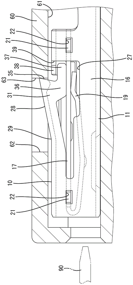
图1是示出本发明的实施例1所涉及的端子零件插入到壳体的腔的状态的侧视图。FIG. 1 is a side view showing a state in which a terminal fitting according to Embodiment 1 of the present invention is inserted into a cavity of a housing.
图2是端子零件的俯视图。Fig. 2 is a plan view of the terminal part.
图3是端子零件的主视图。Fig. 3 is a front view of the terminal part.
图4是端子零件的左侧视图。Fig. 4 is a left side view of the terminal part.
图5是端子零件的右侧视图。Fig. 5 is a right side view of the terminal part.
图6是沿图5的A-A线的剖视图。FIG. 6 is a cross-sectional view taken along line A-A of FIG. 5 .
图7是端子零件的展开图。Fig. 7 is a development view of the terminal part.
具体实施方式Detailed ways
以下示出本发明的优选方式。Preferred embodiments of the present invention are shown below.
(1)被钩挂部可以在矛状件的前端部侧的壁沿着其壁面连续地设置。根据该结构,矛状件与现有的矛状件相比不必形成为特别复杂的结构,能够比较简单地形成被钩挂部。(1) The hooked portion may be continuously provided along the wall surface of the wall on the front end portion side of the lance. According to this structure, compared with the conventional lance, the lance does not need to have a particularly complicated structure, and the hooked portion can be formed relatively simply.
(2)钩挂部可以在端子主体的外壁沿着其壁面连续地设置。根据该结构,端子主体与现有的端子主体相比不必形成为特别复杂的结构,能够比较简单地形成钩挂部。(2) The hook portion may be continuously provided on the outer wall of the terminal body along the wall surface thereof. According to this structure, the terminal main body does not have to be formed in a particularly complicated structure compared with the conventional terminal main body, and the hooking portion can be formed relatively easily.
(3)所述矛状件的所述前端部可以形成为在与所述矛状件的挠曲方向交叉的宽度方向延伸的形状,所述被钩挂部从所述前端部的宽度方向一端侧的壁连续地设置。在矛状件的前端部卡止于腔的壁面的状态下,在拉出力作用于端子零件时,在矛状件的前端部的宽度方向一端侧被钩挂部抵接于钩挂部而被保持为卡止状态,并且在矛状件的前端部的宽度方向另一端侧向宽度方向一端侧倾动而举起,其结果是能够使矛状件的前端部卡止于腔的壁面的卡止量增加。其结果,能够进一步提高端子零件相对于壳体的保持力。(3) The front end portion of the lance may be formed in a shape extending in the width direction intersecting the bending direction of the lance, and the hooked portion may be formed from one end of the front end portion in the width direction The side walls are arranged continuously. In a state where the front end of the lance is locked to the wall surface of the cavity, when a pull-out force acts on the terminal fittings, the hooked portion on the one end side in the width direction of the front end of the lance abuts against the hooked portion and is pulled out. The front end of the lance is held in the locked state, and the other end in the width direction of the front end of the lance is tilted to the one end in the width direction and lifted up. As a result, the front end of the lance can be locked on the wall surface of the cavity. volume increase. As a result, the holding force of the terminal fittings with respect to the housing can be further improved.
<实施例1><Example 1>
根据图1-图7对本发明的实施例1进行说明。本实施例1所涉及的端子零件10在将导电性的金属板冲裁成图7所示的展开形状后,通过进行弯曲加工等而一体成形。端子零件10收纳于连接器的壳体60。另外,在以下说明中,关于前后方向将图1、图2以及图5的左侧作为前侧,上下方向以图1、图3-图6的上下方向为基准。Embodiment 1 of the present invention will be described with reference to FIGS. 1 to 7 . The terminal fitting 10 according to the first embodiment is formed integrally by performing bending processing or the like after punching a conductive metal plate into the developed shape shown in FIG. 7 . The
壳体60为合成树脂制,如图1所示,具有在前后方向贯通的腔61和与腔61交叉并连通的矛状件收纳部62。另外,壳体60具有在矛状件收纳部62的后表面沿着上下方向的卡止面63。在本实施例1的情况下,连接器为非防水型的连接器,在壳体60不组装密封环、橡胶栓等的密封部件。The
端子零件10为所谓的阴端子零件,形成为在前后方向上细长的形状,并从后方插入于壳体60的腔61。如图2、图4以及图5所示,端子零件10具有:筒状的端子主体11;开筒状的线筒部12,其配置于比端子主体11靠后方的位置;以及开筒状的绝缘筒部13,其配置于比线筒部12靠后方的位置。线筒部12在未图示的电线的末端部通过压接而连接于去除包覆部而露出的芯线部。绝缘筒部13通过压接而连接于未图示的电线的末端部中的包覆部。The
如图3以及图6所示,端子主体11整体组装成多边筒状,具有:底壁14,其从线筒部12以及绝缘筒部13连续;一对侧壁15、16,其从底壁14的宽度方向两端立起;内侧顶壁17,其从一个侧壁15的上端部架设到另一个侧壁16;以及外侧顶壁18,其从另一个侧壁16的上端部架设到一个侧壁15,并配置于内侧顶壁17的上侧(外侧)。As shown in FIGS. 3 and 6 , the terminal
在端子主体11内设置有接触部19,接触部19通过将以展开形状从内侧顶壁17的前端向前方突出的舌片部分(参照图7的符号19)向后方折返而形成。当壳体60嵌合到未图示的对方壳体时,被收纳于对方壳体的对方端子零件的阳突片90(参照图1)插入到端子主体11内,通过接触部19与阳突片90弹性地接触,从而两个端子零件被电连接。A
如图3所示,内侧顶壁17整体在宽度方向上大致水平地配置。如图5所示,内侧顶壁17在朝向另一个侧壁16侧的前端部具有前后一对的卡止突起21。在另一个侧壁16,在与各卡止突起21对应的位置具有各卡止突起21进入的前后一对的卡止孔22。As shown in FIG. 3 , the entire
如图4所示,一个侧壁15的上端部在与内侧顶壁17之间通过狭缝孔23以及缺口部24(参照图7)折弯,从而构成为在上下方向呈凹凸状的下侧段部25。As shown in FIG. 4 , the upper end portion of one
如图3所示,外侧顶壁18整体比内侧顶壁17向上侧浮起地配置。在外侧顶壁18中的靠一个侧壁15的部分朝向下侧段部25斜下方倾斜地配置,此外在一个侧壁15的上方向下折弯,如图4所示,在外侧顶壁18的下端部构成有从上方凹凸状地嵌入于下侧段部25的上侧段部26。As shown in FIG. 3 , the outer
如图7所示,在端子主体11中,在以展开形状从另一个侧壁16到外侧顶壁18的区域形成有非闭合环状的(有端ループ状)切口部27,通过切口部27的内侧的板片部分向上方立起,从而如图4以及图5所示,形成从前端到后端的范围向斜上方延伸的矛状件28。矛状件28在从与端子主体11的前部区域相连的切口部27的前端稍微靠后方进入的位置具有称为倾斜的起点的支点部29,矛状件28能够以支点部29作为支点在上下方向挠曲变形。As shown in FIG. 7 , in the terminal
如图6所示,矛状件28具有:沿上下方向的侧板部31,其与另一个侧壁16的壁面无台阶地连续;上板部32,其在上端的宽度方向一端侧沿着宽度方向延伸;以及截面呈弧状的弯曲部33,其将侧板部31和上板部32相连。侧板部31、上板部32以及弯曲部33遍及矛状件28的前后方向的全长地设置。在上板部32的后端部,在与侧板部31相连的一侧相反的一侧的端部连续设置有向下方折弯而延伸的延设部34。As shown in FIG. 6 , the
如图6所示,矛状件28在成为自由端的后端(顶端)具有卡止缘35,卡止缘35遍及侧板部31、上板部32以及延设部34地弯曲成截面大致U字形状。如图4以及图5所示,矛状件28的卡止缘35在侧视时随着接近上端向后倾斜成倒锥形。As shown in FIG. 6 , the
如图1以及图5所示,矛状件28具有被钩挂部36,被钩挂部36在从侧板部31的后端侧向下方突出后,在向后方突出。被钩挂部36与侧板部31同样地,使板面沿着前后方向以及上下方向配置。如图6所示,被钩挂部36以相对于侧板部31在宽度方向(板厚方向)无台阶地连续的方式沿着侧板部31的壁面(板面)连续设置。如图1以及图5所示,被钩挂部36的朝后方的突出部分作为能够抵接于后述的钩挂部的抵接部37,下端在于矛状件28的前方区域(比支点部29靠前方的区域)的切口部27以及内侧顶壁17的上端相同的高度位置沿着前后方向配置。抵接部37的后端位于比卡止缘35的后端(上端)靠后方的位置。As shown in FIGS. 1 and 5 , the
如图7所示,端子主体11在外侧顶壁18的后部的与切口部27相对的部分且在前后方向上与被钩挂部36重叠的位置具有钩挂部38。钩挂部38在外侧顶壁18的后部形成为从沿着前后方向的切口部27的缘部向宽度方向一端侧突出的板片状,并且通过组装端子主体11,从而如图6所示,构成为位于被钩挂部36的抵接部37的上方。钩挂部38与外侧顶壁18的后部的宽度方向另一端侧同样地,使板面沿着前后方向以及宽度方向配置。如图6所示,钩挂部38以相对于外侧顶壁18的后部在上下方向(板厚方向)无台阶地连续的方式沿着外侧顶壁18的后部的壁面(板面)连续设置。As shown in FIG. 7 , the terminal
如图7所示,钩挂部38在外侧顶壁18的后部在与切口部27的后端缘部之间具有沿着宽度方向的狭缝39。钩挂部38的前后长度设定为比抵接部37的前后长度小。As shown in FIG. 7 , the
如图4以及图5所示,端子主体11通过内侧顶壁17的各卡止突起21进入到另一个侧壁16的各卡止孔22,外侧顶壁18的上侧段部26嵌入到一个侧壁15的下侧段部25,从而能够维持筒形状。矛状件28以支点部29为起点折弯。在该情况下,矛状件28通过被钩挂部36的抵接部37的上端抵接到钩挂部38,从而限制矛状件28进一步的折弯曲。也就是说,矛状件28的弯曲量能够由钩挂部38规定。As shown in FIG. 4 and FIG. 5 , the
在端子零件10处于被收纳于壳体60之前的单体状态时,例如若环状的电线等异物钩挂到矛状件28,则可能有如下情况:矛状件28过渡地举起并进一步向前方反转,从而塑性变形。在本实施例1的情况下,通过被钩挂部36的抵接部37的上端抵接于钩挂部38,从而矛状件28的举起动作被限制,由此能够防止矛状件28进行反转。When the terminal fitting 10 is in a single state before being accommodated in the
在端子零件10插入到壳体60的腔61的过程中,上板部32的后端上缘在腔61的壁面滑动,矛状件28以支点部29为支点向下方挠曲变形。然后,当端子零件10正规插入于腔61时,矛状件28弹性复原而嵌入到矛状件收纳部62,矛状件28的卡止缘35与矛状件收纳部62的卡止面63对置,从而能够卡止地配置。由此,端子零件10在腔61内保持为防脱状态(参照图1)。在矛状件28弹性复原而从矛状件收纳部62的卡止面63没有受到实质上的压力的自然状态下,被钩挂部36的抵接部37的上端以与钩挂部38之间稍微隔着间隙的方式配置。When the terminal fitting 10 is inserted into the
在端子零件10正规插入于腔61后,例如若从壳体60的后表面向后方引出的未图示的电线被拉拽,则可能有如下情况:矛状件28的卡止缘35较强地抵接到矛状件收纳部62的卡止面63,矛状件28沿着卡止缘35的倾斜而向上方举起并且向前方反转,从而塑性变形。然而,在本实施例1的情况下,被钩挂部36的抵接部37的上端抵接于钩挂部38,从而限制矛状件28向上方的挠曲动作。其结果,能够防止矛状件28反转。After the terminal fitting 10 is properly inserted into the
特别是,在本实施例1的情况下,由于被钩挂部36在矛状件28的宽度方向一端侧的侧板部31沿着其壁面连续地设置,矛状件28的宽度方向另一端侧成为自由端部,所以在被钩挂部36的抵接部37的上端抵接到钩挂部38的状态下,电线向后方拉拽等从而使得拔出力作用到端子零件10时,矛状件28朝向宽度方向一端侧绕轴倾动,矛状件28的宽度方向另一端侧向上方移位从而能够使与卡止面63的卡止量增加。In particular, in the case of the first embodiment, since the hooked
如以上说明的那样,根据本实施例1,不仅是端子零件10被收纳于壳体60的状态,即使在端子零件10处于被收纳于壳体60之前的单体状态的情况下,由于通过矛状件28的被钩挂部36抵接到外侧顶壁18的钩挂部38,从而限制矛状件28的反转动作,所以能够确实地防止矛状件28折损。因此,能够使矛状件28牢固地卡止于壳体60,能够提高端子零件10相对于壳体60的保持力。As described above, according to the first embodiment, not only the state where the
另外,由于被钩挂部36在矛状件28的侧板部31的后端侧(顶端侧)沿着其壁面连续地设置,所以矛状件28与现有矛状件相比不必形成为特别复杂的结构,能够比较简单地形成被钩挂部36。并且,由于钩挂部38也在端子主体11的外侧顶壁18沿其壁面连续地设置,所以端子主体11也与现有的端子主体相比不必形成为特别复杂的结构,能够比较简单地形成钩挂部38。In addition, since the hooked
此外,由于被钩挂部36在矛状件28的侧板部31的后端部从宽度方向一端侧连续地设置,所以在矛状件28的卡止缘35卡止于矛状件收纳部62的卡止面63的状态下,电线向后方拉拽时,在矛状件28的后端部的宽度方向一端侧被钩挂部36抵接到钩挂部38而保持为卡止状态,并且在矛状件28的后端部的宽度方向另一端侧朝向宽度方向一端侧倾动并被举起。其结果,能够使矛状件28的卡止缘35卡止于矛状件收纳部62的卡止面63的卡止量增加,能够进一步提高端子零件10相对于壳体60的保持力。In addition, since the hooked
<其他实施例><Other Examples>
以下,简单地说明其他实施例。Hereinafter, other embodiments will be briefly described.
(1)被钩挂部也可以在矛状件的后端部的宽度方向两个端部成对地连续设置。另外,被钩挂部也可以在矛状件的后端部的宽度方向中央部连续设置。(1) The hooked portions may be continuously provided in pairs at both end portions in the width direction of the rear end portion of the lance. In addition, the hooked portion may be continuously provided in the width direction central portion of the rear end portion of the lance.
(2)被钩挂部也可以是在自然状态下维持与钩挂部抵接的状态的结构。(2) The hooked portion may be configured to maintain a state in which the hooked portion is in contact with the hooked portion in a natural state.
(3)端子零件也可以是阳突片从端子主体向前方突出的阳端子零件。在这种情况下,可以从端子主体内省略接触部。(3) The terminal fittings may be male terminal fittings in which male tabs protrude forward from the terminal body. In this case, the contact portion can be omitted from the terminal body.
附图标记说明Description of reference numerals
10…端子零件10…Terminal parts
11…端子主体11...Terminal body
28…矛状件28…Spear
31…侧板部31...Side plate
35…卡止缘35…Locking edge
36…被钩挂部36...Hooked part
37…抵接部37…Abutting part
38…钩挂部38...Hook part
60…壳体60…shell
61…腔61…Cavity
63…卡止面63…Locking surface
Claims (4)
Applications Claiming Priority (2)
| Application Number | Priority Date | Filing Date | Title |
|---|---|---|---|
| JP2018224417A JP2020087844A (en) | 2018-11-30 | 2018-11-30 | Terminal fitting |
| JP2018-224417 | 2018-11-30 |
Publications (2)
| Publication Number | Publication Date |
|---|---|
| CN111262082A true CN111262082A (en) | 2020-06-09 |
| CN111262082B CN111262082B (en) | 2021-12-21 |
Family
ID=70680881
Family Applications (1)
| Application Number | Title | Priority Date | Filing Date |
|---|---|---|---|
| CN201911164925.9A Expired - Fee Related CN111262082B (en) | 2018-11-30 | 2019-11-25 | Terminal fitting |
Country Status (4)
| Country | Link |
|---|---|
| US (1) | US20200176917A1 (en) |
| JP (1) | JP2020087844A (en) |
| CN (1) | CN111262082B (en) |
| DE (1) | DE102019007795A1 (en) |
Families Citing this family (8)
| Publication number | Priority date | Publication date | Assignee | Title |
|---|---|---|---|---|
| JP6816668B2 (en) * | 2017-07-11 | 2021-01-20 | 株式会社オートネットワーク技術研究所 | connector |
| JP6544412B2 (en) * | 2017-11-22 | 2019-07-17 | オムロン株式会社 | Connector terminals and connectors |
| US11831118B2 (en) | 2019-08-29 | 2023-11-28 | J.S.T. Corporation | Electrical male terminal |
| US11626671B2 (en) * | 2019-08-29 | 2023-04-11 | J.S.T. Corporation | Electrical male terminal |
| JP7401500B2 (en) * | 2020-10-13 | 2023-12-19 | ティーイー コネクティビティ ジャーマニー ゲゼルシャフト ミット ベシュレンクテル ハフツンク | electrical terminals |
| DE102020126888A1 (en) | 2020-10-13 | 2022-04-14 | Te Connectivity Germany Gmbh | Electrical terminal |
| DE102021100806A1 (en) | 2021-01-15 | 2022-07-21 | Te Connectivity Germany Gmbh | Contact device and method for producing the contact device |
| JP7480718B2 (en) * | 2021-01-25 | 2024-05-10 | 住友電装株式会社 | connector |
Citations (9)
| Publication number | Priority date | Publication date | Assignee | Title |
|---|---|---|---|---|
| WO1998019366A1 (en) * | 1996-10-29 | 1998-05-07 | The Whitaker Corporation | Contact with latch for contact retention and housing therefor |
| CN1685573A (en) * | 2002-09-25 | 2005-10-19 | 菱星电装株式会社 | Electric connector |
| CN101488616A (en) * | 2008-01-17 | 2009-07-22 | 住友电装株式会社 | A connector |
| CN103563181A (en) * | 2011-06-17 | 2014-02-05 | 矢崎总业株式会社 | Terminal fitting |
| US20140322995A1 (en) * | 2013-04-26 | 2014-10-30 | Delphi Technologies, Inc. | Electrical terminal with a locking lance |
| CN104916945A (en) * | 2014-03-13 | 2015-09-16 | 住友电装株式会社 | Connector |
| CN105322326A (en) * | 2014-06-12 | 2016-02-10 | 第一精工株式会社 | Electric terminal |
| CN105914510A (en) * | 2016-04-14 | 2016-08-31 | 安徽江淮汽车股份有限公司 | Clamp structure of wiring harness terminal |
| JP2017168445A (en) * | 2016-03-16 | 2017-09-21 | ティーイー コネクティビティ ジャーマニー ゲゼルシャフト ミット ベシュレンクテル ハフツンクTE Connectivity Germany GmbH | Electrical contact device, electrical contact unit, and electrical connector |
Family Cites Families (13)
| Publication number | Priority date | Publication date | Assignee | Title |
|---|---|---|---|---|
| FR2741204A1 (en) * | 1995-11-14 | 1997-05-16 | Amp France | ASSEMBLY OF ELECTRICAL CONNECTOR |
| JP3518178B2 (en) * | 1996-07-25 | 2004-04-12 | 住友電装株式会社 | Female terminal fitting |
| JP3575583B2 (en) * | 1997-03-25 | 2004-10-13 | 矢崎総業株式会社 | Terminal |
| FR2765033B1 (en) * | 1997-06-24 | 1999-08-06 | Framatome Connectors Int | MINIATURE ELECTRICAL CONTACT |
| US6024612A (en) * | 1997-09-23 | 2000-02-15 | The Whitaker Corporation | Receptacle contact |
| DE10335196B3 (en) * | 2003-07-30 | 2005-04-07 | Yazaki Europe Ltd., Hemel Hempstead | Contact socket for a flat plug |
| DE10349539B3 (en) * | 2003-10-22 | 2005-06-16 | Yazaki Europe Ltd., Hemel Hempstead | Electrical contact element |
| DE102007040937B3 (en) * | 2007-08-30 | 2009-01-15 | Tyco Electronics Amp Gmbh | Electric contact |
| WO2011053276A1 (en) * | 2009-10-26 | 2011-05-05 | Molex Incorporated | Miniature receptacle terminals |
| DE102013223570B4 (en) * | 2013-11-19 | 2021-06-24 | Te Connectivity Germany Gmbh | Pin contact with a contact body manufactured as a stamped and bent part and a solid contact pin |
| US10122108B2 (en) * | 2014-04-24 | 2018-11-06 | Molex, Llc | Terminal fitting |
| JP2017139213A (en) * | 2015-11-30 | 2017-08-10 | タイコ エレクトロニクス (シャンハイ) カンパニー リミテッド | Connection terminal and connection assembly |
| JP6551204B2 (en) * | 2015-12-14 | 2019-07-31 | 住友電装株式会社 | Terminal fitting |
-
2018
- 2018-11-30 JP JP2018224417A patent/JP2020087844A/en active Pending
-
2019
- 2019-11-11 DE DE102019007795.4A patent/DE102019007795A1/en not_active Withdrawn
- 2019-11-25 US US16/693,654 patent/US20200176917A1/en not_active Abandoned
- 2019-11-25 CN CN201911164925.9A patent/CN111262082B/en not_active Expired - Fee Related
Patent Citations (9)
| Publication number | Priority date | Publication date | Assignee | Title |
|---|---|---|---|---|
| WO1998019366A1 (en) * | 1996-10-29 | 1998-05-07 | The Whitaker Corporation | Contact with latch for contact retention and housing therefor |
| CN1685573A (en) * | 2002-09-25 | 2005-10-19 | 菱星电装株式会社 | Electric connector |
| CN101488616A (en) * | 2008-01-17 | 2009-07-22 | 住友电装株式会社 | A connector |
| CN103563181A (en) * | 2011-06-17 | 2014-02-05 | 矢崎总业株式会社 | Terminal fitting |
| US20140322995A1 (en) * | 2013-04-26 | 2014-10-30 | Delphi Technologies, Inc. | Electrical terminal with a locking lance |
| CN104916945A (en) * | 2014-03-13 | 2015-09-16 | 住友电装株式会社 | Connector |
| CN105322326A (en) * | 2014-06-12 | 2016-02-10 | 第一精工株式会社 | Electric terminal |
| JP2017168445A (en) * | 2016-03-16 | 2017-09-21 | ティーイー コネクティビティ ジャーマニー ゲゼルシャフト ミット ベシュレンクテル ハフツンクTE Connectivity Germany GmbH | Electrical contact device, electrical contact unit, and electrical connector |
| CN105914510A (en) * | 2016-04-14 | 2016-08-31 | 安徽江淮汽车股份有限公司 | Clamp structure of wiring harness terminal |
Also Published As
| Publication number | Publication date |
|---|---|
| CN111262082B (en) | 2021-12-21 |
| JP2020087844A (en) | 2020-06-04 |
| US20200176917A1 (en) | 2020-06-04 |
| DE102019007795A1 (en) | 2020-06-04 |
Similar Documents
| Publication | Publication Date | Title |
|---|---|---|
| CN111262082A (en) | Terminal fitting | |
| US7556539B2 (en) | Connector | |
| CN100576643C (en) | Connector | |
| KR101065811B1 (en) | connector | |
| EP2355255B1 (en) | Terminal fitting and connector provided therewith | |
| JP2001351737A (en) | Half mating prevention connector | |
| CN101252236A (en) | Connector | |
| EP1983618A2 (en) | A connector | |
| CN105191009A (en) | Connector | |
| JP2011181330A (en) | Terminal fitting | |
| CN110649410B (en) | Terminal Metal Fittings | |
| CN110649412B (en) | Terminal metal fitting and fitting structure of terminal metal fitting and housing | |
| CN100454678C (en) | Connectors and intermediate connectors | |
| EP2493025A2 (en) | Connector | |
| JPH0734575U (en) | connector | |
| JP4062250B2 (en) | connector | |
| KR20170070997A (en) | Locking structure of connector and connector | |
| JP2004362973A (en) | Terminal fitting | |
| CN111033904A (en) | Connector with a locking member | |
| CN113571962A (en) | Connector and connector assembly | |
| CN100541927C (en) | Connector | |
| CN118525422A (en) | Terminal and connector | |
| US20200358238A1 (en) | Terminal Extraction Jig | |
| KR200428338Y1 (en) | connector | |
| JP2005158418A (en) | Connector |
Legal Events
| Date | Code | Title | Description |
|---|---|---|---|
| PB01 | Publication | ||
| PB01 | Publication | ||
| SE01 | Entry into force of request for substantive examination | ||
| SE01 | Entry into force of request for substantive examination | ||
| GR01 | Patent grant | ||
| GR01 | Patent grant | ||
| CF01 | Termination of patent right due to non-payment of annual fee |
Granted publication date: 20211221 |
|
| CF01 | Termination of patent right due to non-payment of annual fee |