Background
Implantable medical devices (implants) are ubiquitous to provide diagnostic or therapeutic capabilities. Three types of active implant products, such as an Implantable Cardiac Defibrillator (ICD), an Implantable Cardiac Monitor (ICM), an implantable Cardiac Pacemaker (cardioc Pacemaker), a leadless implantable Cardiac Pacemaker, a Subcutaneous Implantable Cardiac Defibrillator (SICD), various tissue, organ and nerve stimulators or sensors, generally require doctors or professionals to realize wireless communication between an external program controller and an implant stimulator to complete possible functions of data transmission, implant software upgrading, emergency stop and the like. The invention aims to solve the problems of wireless communication efficiency and communication quality, improve wireless transmission efficiency and avoid unsmooth or failed communication.
The traditional communication mode carries out wireless communication at a distance of a few centimeters in an inductive near-field coupling mode, and the traditional communication mode has the following defects: the communication distance is too close, the use mode is limited and the data rate is low, and the data rate is generally thousands or tens of thousands of bits.
With the advance of technology, the remote communication between the implant circuit and the external program controller and other remote control devices becomes possible, and the application in the aspects of device control, data transmission, real-time monitoring and the like is more and more common, and the implant and the external device can communicate at a distance of several meters. As one of the hardware bases of communication, the implant antenna is placed in the connector outside the shell, so that the energy radiated by the antenna is not absorbed by the metal shell and is conducted out to the maximum extent.
With the increasing integration and miniaturization of circuits and structures, the physical space of antennas is limited. Generally, the communication distance is related to the radiation efficiency/gain of the antenna, the transmission power of the transmitting antenna, and the sensitivity of the receiving antenna. The efficiency/gain of the antenna is positively correlated to the size of the antenna. In order to increase the antenna efficiency and the maximum transmission distance to the maximum, designers have proposed various schemes. For example, the communication frequency and the decoding mode are modified, so that the system has better sensitivity to signals under the same hardware condition; or try to design a more directional antenna in anticipation of achieving better efficiency in a certain direction; or a matching network is added to achieve smaller return loss and better radiation efficiency, and longer transmission distances can be achieved at specific frequencies. These methods are generally undesirable because they either deviate from the frequency band of communication allowed by the implant in practice, or require additional requirements during the procedure, or are difficult to maintain communication stability in changing environments and add to the devices required.
Generally, to achieve a desired antenna efficiency, the total length of the antenna needs to be at least one-quarter to one-half wavelength. A reduction in antenna length reduces the radiation impedance of the antenna, making it more difficult to match the antenna to the source and couple to the air impedance, thereby significantly reducing antenna efficiency. This example presents a solution to increase the effective radiation efficiency of an antenna that obtains better radiation capability by bending multiple times in three dimensions and coupling with the housing.
Disclosure of Invention
The invention provides an antenna which comprises three parts, wherein the first part comprises two L-shaped sections ABC and DEF and a circular arc section CD connecting the short sides of the two L-shaped sections. The plane of the two L-shaped sections ABC and DEF is vertical to each other, the lengths of two sides AB and EF of the two L-shaped sections are different and are positioned on the same side of the plane of the two short sides BC and DE, the second part is a bending section GH positioned on the same plane, the plane of the bending section is vertical to the plane of the two L-shaped sections in the first part, the third part is an arc section FG, and the longest edge EF of the L-shaped section of the first part is connected with the bending section GH of the second part.
The antenna is used for MICS microwave communication, and the working frequency is MICS402MHz to 405 MHz.
The antenna is a monopole antenna without a corresponding dual structure.
The bending section of the antenna comprises a vertical Z shape, a plurality of continuous vertical Z shapes, a horizontal Z shape, a plurality of continuous horizontal Z shapes, a horizontal trapezoid, a plurality of continuous horizontal trapezoids, a vertical trapezoid, a plurality of continuous vertical trapezoids, a horizontal W shape, a plurality of continuous horizontal W shapes, a vertical W shape and a plurality of continuous vertical W shapes.
The circular arc section CD of the first part of the antenna is perpendicular to the plane where the third part circular arc section FG is located, and the third part circular arc section FG is parallel to the plane where the L-shaped section with the shorter long edge in the first part is located.
The invention provides an implantable medical device, which consists of four parts, namely a device shell (equipment shell), a hybrid circuit, an antenna and a feed-through assembly, wherein the antenna comprises three parts, and the first part comprises two L-shaped sections ABC and DEF and an arc section CD connecting the short sides of the two L-shaped sections. The plane of the two L-shaped sections ABC and DEF is vertical to each other, the lengths of two sides AB and EF of the two L-shaped sections are different and are positioned on the same side of the plane of the two short sides BC and DE, the second part is a bending section GH positioned on the same plane, the plane of the bending section is vertical to the plane of the two L-shaped sections in the first part, the third part is an arc section FG, and the longest edge EF of the L-shaped section of the first part is connected with the bending section GH of the second part.
The antenna is connected to the medical device body through a feedthrough assembly and is encapsulated within the feedthrough assembly.
The radiation part of the implanted medical device is composed of an antenna body and an implant shell together.
The implanted medical device and the external program controller are respectively provided with a set of hardware configuration comprising a radio frequency antenna, a radio frequency chip and corresponding software.
The antenna is connected with the medical device main body through a section surface formed by connecting an arc section and a plane section.
The edge line of the medical device is parallel to the plane of the L-shaped section of the first part of the antenna, which section contains the shorter long side.
The antenna is turned over for the last time below the antenna parallel to the shell, and the parallel part can change the shell into a part of radiation parts through coupling, so that the signal transmission efficiency is improved.
The invention discloses an implantable medical device capable of realizing signal transmission between an external remote device and an external remote device through an antenna. In some examples, the implantable medical device is capable of automatically completing triggering of sensing of cardiac electrical signal parameters internal to the heart, e.g., without a triggering input initiated from an external source, e.g., based on a request initiated from the patient or initiated by a physician from an external device, and transmitting the sensed physiological parameters to the exogenous far-field device based at least in part on one or more physiological parameters of the patient.
Detailed Description
Fig. 1 is a schematic perspective view of an antenna. The antenna shown in fig. 1 is taken as an example to illustrate the specific operation process of the antenna in the implantable medical device. For ease of illustration and description, fig. 1 labels the various nodes of the antenna from one end of the antenna to the other according to the letter A, B, C, D, E, F, G, H, I, J. The antenna comprises three parts, wherein the first part is a part marked from letters A to F and comprises two L-shaped sections ABC and DEF and a circular arc section CD connecting the short sides of the two L-shaped sections. As can be seen in fig. 6, the planes ii and iii of the two L-shaped sections ABC and DEF are perpendicular to each other, and the two sides AB and EF of the two L-shaped sections are different in length and are located on the same side of the plane defined by the two short sides BC and DE, i.e., the plane i. The second part is the part from letter G to J, comprising a bend GH in the same plane. The third part is a circular arc section FG, and the end point F of the longest edge of the L-shaped section of the first part is connected with the starting point G of the bending section of the second part. A plane I where a circular arc section CD of a first part of the antenna is located is perpendicular to a plane II where a third part circular arc section FG is located, and the third part circular arc section FG is parallel to a plane III where an L-shaped section DEF with a short long edge in the first part is located. The antenna as a whole constitutes a monopole antenna without a reflection plate portion. The monopole antenna has the greatest characteristic of providing satisfactory radiation characteristics over a wide frequency band, and has the advantages of simple structure, light weight, simple feed structure, convenience in analysis, good omnidirectional characteristics and the like. The raw material of the antenna can be copper plate or tin-plated steel plate. The working principle of the antenna is MICS microwave communication, and the working frequency of the antenna is from MICS402MHz to MICS 405 MHz. The effective radiation efficiency of the antenna is increased through high frequency, and better radiation capability is obtained through multiple bending in three-dimensional space. The antenna can be packaged in implantable cardiac defibrillators, implantable cardiac monitors, implantable cardiac pacemakers, leadless implantable cardiac pacemakers, subcutaneous implantable cardiac defibrillators, and implantable medical devices such as various tissues, organs, and neurostimulators or sensors, wherein the structural schematic diagram of the antenna mounted to the subcutaneous implantable cardiac defibrillator is shown in fig. 5 and 6. The antenna is connected with an internal circuit board of the implanted medical device for communication, so that far-field communication between the implanted medical device and external remote equipment is realized. The width of the antenna can be adjusted according to the used implanted medical device, and can be fixed by widening any section of the main structure of the antenna shown in fig. 1 and selecting a proper way, including the following fixing ways: the mechanical structure fixation, glue bonding, bolt connection, welding and riveting are carried out through punching, the shaft is in interference fit with the hole, the shaft is in transition fit with the hole in clearance fit, the shaft is in keyed connection and then is compressed by threads, and the like. The antenna should be encapsulated inside the implanted medical device and the antenna length should be as long as possible, enhancing the signal transmission sensitivity of the antenna.
Fig. 2 is a schematic perspective view of the antenna as viewed from the direction indicated by the arrow R in fig. 1. The second part of the antenna is a bending section GH, the bending section GH is in the same plane, fig. 2 shows a shape of the bending section, and in an actual operation process, the bending section can be designed as one or a combination of more of a vertical Z type, a plurality of continuous vertical Z types, a horizontal Z type, a plurality of continuous horizontal Z types, a horizontal trapezoid, a plurality of continuous horizontal trapezoids, a plurality of continuous vertical trapezoids, a horizontal W type, a plurality of continuous horizontal W types, a vertical W type and a plurality of continuous vertical W types besides the vertical trapezoid shown in fig. 2. But it is necessary to ensure that the plane i of the bent sections of various shapes is perpendicular to the planes ii and iii of the two L-shaped sections ABC and DEF in the first section.
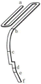
Fig. 3 is a schematic perspective view of another antenna. For ease of illustration and description, fig. 3 labels the various nodes of the antenna from one end of the antenna to the other by letters a, b, c, d, e, f. The antenna comprises three parts, the first part being the part marked from the letter a to b, as an S-shaped segment. Fig. 3 differs from fig. 1 only in the first part of the antenna. The second part of fig. 3 is the part from letter b to c, comprising one bending section cd in the same plane. The third part is a circular segment bc connecting the S-shaped segment of the first part with the bent segment of the second part. The plane I where the S-shaped section ab of the first part of the antenna is located is perpendicular to the plane II where the circular arc section bc of the third part is located. The antenna is connected to the device hybrid circuit by an integral structure consisting of a circular arc section de and a planar section ef.
Implantable medical devices (implants) are ubiquitous to provide diagnostic or therapeutic capabilities. Three types of active implant products, namely an implantable cardiac defibrillator, an implantable cardiac monitor, an implantable cardiac pacemaker, a leadless implantable cardiac pacemaker, a subcutaneous implantable cardiac defibrillator, various tissues, organs, nerve stimulators or sensors and the like, generally need doctors or professionals to realize wireless communication between an external program controller and an implant stimulator to complete possible functions of data transmission, implant software upgrading, emergency stop and the like. This embodiment takes an ICD as an example to illustrate the working scheme of the antenna in the implantable medical device.
Fig. 4 is a schematic diagram of the external structure of ICD100 and the relative positions of the components in the heart when implanted inside the heart. The ICD is made up of four parts, a device housing 105, a hybrid circuit in the device housing, an antenna, and a feedthrough assembly. The antenna is encapsulated within a feedthrough assembly of the ICD header structure 107 that encapsulates not only the antenna feedthrough, but also the lead feedthrough inside. Lead feedthrough see ICD head structure in fig. 5, lead feedthrough is connected to lead 115, and the ICD main body circuit board is connected to the heart via antenna for sensing cardiac signal parameters or treatment by clicking. The device shell interior usually comprises a power supply, a capacitor and a hybrid circuit, and the hybrid circuit is usually realized by a chip through a program coding mode. The exertion of ICD function can be realized through two kinds of modes, one kind is the inside automatic formula regulation and control of ICD organism, does not need artificial manual trigger and control, can realize automatically. Another implementation is by the external programming device 190 sending the communication signal 185, typically a programmer, patient assistant, or other device capable of commanding it or sensing its internal signals. The communication mode between the ICD and the external programmable device 190 may be one or more of wired communication, bluetooth, WIFI, LTE, CDMA, and other wireless communication networks. ICD lead 115 shown in FIG. 1 is a single lead, and may be a double lead, a triple lead, or a quadruple lead during clinical use, with the basic lead structure being similar to lead 115. Lead 115 is formed from coil 118 electrode 120A and electrode 120B, coil 118 being connected to the ICD subject via connector 107, the coil functioning as: the sensing or treatment purpose is achieved through electric discharge. The signal parameters of the cardiac event are sensed by electrodes 120A and 120B, also called helical heads, which contain helical coils inside of electrode 120B. The electrode spiral 120A on the lead is screwed in the insulating material on the periphery of the lead before use, and can be screwed out from the other end of the lead before being implanted into the heart of a human body, so that the electrode end 120A of the lead is fixed with myocardial tissue in the heart. The electrode lead needs to be coated by insulating materials such as silica gel, polyurethane or epoxy resin.
Fig. 5 is a schematic diagram of an antenna structure of the antenna shown in fig. 1 according to a fixing method. The dashed lines in fig. 5 represent the antenna portions, which are enclosed by dashed lines, and do not represent planes. The difference between the antenna of fig. 5 and the antenna of fig. 1 is the dashed line drawn out portion 208, and the antenna of fig. 4 is further processed in the portion of the long side EF of the L-section DEF of the first portion of the antenna of fig. 1. The antenna 202 of fig. 4 widens the width of the long EF section of the L-section DEF of the antenna of fig. 2, and perforations 206 are made in the widened section 204, the number of which is 0 to 10, the size of which can be adjusted in conjunction with the size of the particular medical device, the holes of the antenna being used to fix the fixed antenna within the ICD head. The fixing mode can be selected from glue bonding, bolt connection, welding, riveting, fit interference fit of the shaft and the hole, fit transition fit clearance fit of the shaft and the hole, key connection and thread pressing.
Fig. 6 is a schematic diagram of the location of the antenna shown in fig. 1 mounted to an implantable medical device ICD. 316 is the shell of the medical device, the shell of the device contains a hybrid circuit to sense and communicate the electrocardio parameters of the implanted device. A feedthrough assembly is encapsulated within the header of the ICD, the feedthrough assembly including an antenna feedthrough and a lead feedthrough. The antenna feedthrough is a component connecting the antenna and the device body. One end of the antenna 320 is connected to the internal circuit board of the main body of the device through the antenna feeding passage 312, and the other end is opened or connected to the internal circuit of the stimulator to form a loop. The conductors are fed through 1 to 5 conductors 308 connected to the hybrid circuit inside the device body 316, the location of the conductors to access the hybrid circuit being designed to a range area, shown here as access area 310. The lead feedthrough assembly includes four silicone insulators 318 to separate the three conductors 302 and prevent communication between the conductors and shorting the device. The antenna is connected with the medical device hybrid circuit through an integral structure formed by connecting a circular arc section HI and a plane section IJ. The ground line 314 connects the circuit board inside the device to the ground to form a loop for transmitting wireless signals. The ICD and the external program control instrument are respectively provided with a set of hardware configuration comprising a radio frequency antenna, a radio frequency chip and corresponding software configuration. The lead wire feed-through is provided with a fixing component 304, and the fixing mode comprises the following steps: glue bonding and fixing, mechanical structure fixing, bolt connection, welding and riveting. Meanwhile, the fixing structure 304 is a conductive body with a conductive function, and connects the antenna 320 with a circuit board embedded in the medical device, so that the antenna is connected with a circuit in the device to perform a wireless communication function.
Fig. 7 is a schematic view of the position of the antenna mounted to the implantable medical device ICD, as seen in the direction of arrow T in fig. 6. In fig. 7, the dashed lines represent the planes where the dashed lines are located, every four dashed lines enclose a dashed line frame, one dashed line frame is located on one plane, and in the figure, three dashed line frames represent three planes where three dashed line frames are located respectively, and the three planes are perpendicular to each other two by two. The antenna 406 is folded for the last time below the ICD shell, the plane III where the L-shaped section DEF with the shorter long edge is located in the first part of the antenna 406 is parallel to the edge line of the antenna shell, the device shell 402 which is in direct contact with human tissue is made of conductive metal titanium, and the parallel part AB can change the shell 402 into a partial radiation part through coupling, so that the antenna body 320 and the implant shell 316 jointly form the radiation part of the implanted medical device, and the signal transmission efficiency is improved. The lead feedthrough on the ICD header contains four silicone insulators 404, identical to 318 in FIG. 3. Reference numeral 408 is a fixation site mounted to the assembly 304 in fig. 3, by which fixation the lead feedthrough is fixed to the head of the implanted medical device ICD. The fixing means of the fixing portion 408 includes: mechanical structure fixing, glue bonding, bolt connection, welding, riveting, fit interference fit of a shaft and a hole, fit transition fit clearance fit of the shaft and the hole, key connection and thread pressing and the like.
The invention discloses a special-shaped antenna applicable to wireless communication of an implanted medical device, which is designed into a three-dimensional shape, the antenna of the medical device is folded for the last time below the antenna parallel to a shell, the parallel part can increase the capacitance between the antenna and the shell, and the shell can be changed into a partial radiation part through coupling, so that the radiation caliber of the antenna is increased to the maximum extent, the two-dimensional area of the antenna is reduced, the radiation efficiency is improved, and the energy transmission efficiency and the data transmission distance are improved.