CN111261905B - A real-time monitoring method of single-flow battery power - Google Patents
A real-time monitoring method of single-flow battery power Download PDFInfo
- Publication number
- CN111261905B CN111261905B CN202010071200.1A CN202010071200A CN111261905B CN 111261905 B CN111261905 B CN 111261905B CN 202010071200 A CN202010071200 A CN 202010071200A CN 111261905 B CN111261905 B CN 111261905B
- Authority
- CN
- China
- Prior art keywords
- electrolyte
- conductivity
- flow battery
- charging
- single flow
- Prior art date
- Legal status (The legal status is an assumption and is not a legal conclusion. Google has not performed a legal analysis and makes no representation as to the accuracy of the status listed.)
- Active
Links
Images

Classifications
-
- H—ELECTRICITY
- H01—ELECTRIC ELEMENTS
- H01M—PROCESSES OR MEANS, e.g. BATTERIES, FOR THE DIRECT CONVERSION OF CHEMICAL ENERGY INTO ELECTRICAL ENERGY
- H01M8/00—Fuel cells; Manufacture thereof
- H01M8/18—Regenerative fuel cells, e.g. redox flow batteries or secondary fuel cells
- H01M8/184—Regeneration by electrochemical means
- H01M8/188—Regeneration by electrochemical means by recharging of redox couples containing fluids; Redox flow type batteries
-
- H—ELECTRICITY
- H01—ELECTRIC ELEMENTS
- H01M—PROCESSES OR MEANS, e.g. BATTERIES, FOR THE DIRECT CONVERSION OF CHEMICAL ENERGY INTO ELECTRICAL ENERGY
- H01M8/00—Fuel cells; Manufacture thereof
- H01M8/04—Auxiliary arrangements, e.g. for control of pressure or for circulation of fluids
- H01M8/04298—Processes for controlling fuel cells or fuel cell systems
- H01M8/04313—Processes for controlling fuel cells or fuel cell systems characterised by the detection or assessment of variables; characterised by the detection or assessment of failure or abnormal function
- H01M8/04537—Electric variables
- H01M8/04604—Power, energy, capacity or load
- H01M8/04611—Power, energy, capacity or load of the individual fuel cell
-
- H—ELECTRICITY
- H01—ELECTRIC ELEMENTS
- H01M—PROCESSES OR MEANS, e.g. BATTERIES, FOR THE DIRECT CONVERSION OF CHEMICAL ENERGY INTO ELECTRICAL ENERGY
- H01M8/00—Fuel cells; Manufacture thereof
- H01M8/04—Auxiliary arrangements, e.g. for control of pressure or for circulation of fluids
- H01M8/04298—Processes for controlling fuel cells or fuel cell systems
- H01M8/04992—Processes for controlling fuel cells or fuel cell systems characterised by the implementation of mathematical or computational algorithms, e.g. feedback control loops, fuzzy logic, neural networks or artificial intelligence
-
- Y—GENERAL TAGGING OF NEW TECHNOLOGICAL DEVELOPMENTS; GENERAL TAGGING OF CROSS-SECTIONAL TECHNOLOGIES SPANNING OVER SEVERAL SECTIONS OF THE IPC; TECHNICAL SUBJECTS COVERED BY FORMER USPC CROSS-REFERENCE ART COLLECTIONS [XRACs] AND DIGESTS
- Y02—TECHNOLOGIES OR APPLICATIONS FOR MITIGATION OR ADAPTATION AGAINST CLIMATE CHANGE
- Y02E—REDUCTION OF GREENHOUSE GAS [GHG] EMISSIONS, RELATED TO ENERGY GENERATION, TRANSMISSION OR DISTRIBUTION
- Y02E60/00—Enabling technologies; Technologies with a potential or indirect contribution to GHG emissions mitigation
- Y02E60/30—Hydrogen technology
- Y02E60/50—Fuel cells
Landscapes
- Engineering & Computer Science (AREA)
- Life Sciences & Earth Sciences (AREA)
- Manufacturing & Machinery (AREA)
- Sustainable Development (AREA)
- Sustainable Energy (AREA)
- Chemical & Material Sciences (AREA)
- Chemical Kinetics & Catalysis (AREA)
- Electrochemistry (AREA)
- General Chemical & Material Sciences (AREA)
- Artificial Intelligence (AREA)
- Health & Medical Sciences (AREA)
- Automation & Control Theory (AREA)
- Computing Systems (AREA)
- Evolutionary Computation (AREA)
- Fuzzy Systems (AREA)
- Medical Informatics (AREA)
- Software Systems (AREA)
- Theoretical Computer Science (AREA)
- Secondary Cells (AREA)
- Battery Electrode And Active Subsutance (AREA)
Abstract
Description
技术领域technical field
本发明涉及单液流电池领域,具体地涉及一种单液流电池电量的实时监控方法。The invention relates to the field of single flow batteries, in particular to a method for real-time monitoring of the electric quantity of a single flow battery.
背景技术Background technique
大功率、大容量储能电站电池是解决新能源如风能、太阳能等新能源发电的不稳定、不连续特性有效途径。美国能源部最新报道液流电池目前能够满足兆瓦甚至吉瓦级储能功率及容量的要求。其中,单液流电池是近几年新兴的采用单一电解液的液流电池,适用于兆瓦甚至吉瓦级新能源装机容量的要求,因其采用单一电解液,无质子交换膜,具有成本低,结构简单,转化效率高,长寿命等特点而备受关注。High-power, large-capacity energy storage power station batteries are an effective way to solve the unstable and discontinuous characteristics of new energy such as wind energy and solar energy. According to the latest report from the U.S. Department of Energy, flow batteries can currently meet the requirements for megawatt or even gigawatt-level energy storage power and capacity. Among them, the single-flow battery is a new flow battery using a single electrolyte in recent years, which is suitable for the installed capacity of megawatts or even gigawatts of new energy. Because it uses a single electrolyte and has no proton exchange membrane, it has low cost. Low cost, simple structure, high conversion efficiency, long life and other characteristics have attracted much attention.
单液流电池的原理是采用可溶性的铅盐溶液为电解液,如甲基磺酸铅、三氟甲基磺酸铅、氟硼酸铅、氟硅酸铅、高氯酸铅等,充电时可溶性铅离子Pb2+在外电场的作用下分别氧化还原生成PbO2和Pb沉积在正负极表面,放电时正负极表面的PbO2和Pb通过外电路组成回路自发反应生成Pb2+回到电解液中,形成电流供给用电负载。电解液通过循环系统不断地在电解液槽与电堆之间循环,能够有效地减少或消除电池的浓差极化,提高充放电电流密度及电池效率。同时电池功率取决于电堆数量及电堆中的极板数量,电池容量取决于电极表面沉积活性物质的量,部分实现了容量和功率的分离,便于控制管理。因其使用统一电解液,有效地解决了电堆间的充电状态不平衡问题,可以做到兆瓦及吉瓦级别。The principle of single flow battery is to use soluble lead salt solution as electrolyte, such as lead methanesulfonate, lead trifluoromethanesulfonate, lead fluoroborate, lead fluorosilicate, lead perchlorate, etc. Lead ions Pb 2+ are oxidized and reduced under the action of an external electric field to form PbO 2 and Pb, which are deposited on the surface of the positive and negative electrodes. When discharging, the PbO 2 and Pb on the surface of the positive and negative electrodes spontaneously react through an external circuit to form a loop to generate Pb 2+ and return to the electrolysis In the liquid, a current is formed to supply the electric load. The electrolyte is continuously circulated between the electrolyte tank and the stack through the circulation system, which can effectively reduce or eliminate the concentration polarization of the battery, and improve the charge and discharge current density and battery efficiency. At the same time, the power of the battery depends on the number of stacks and the number of plates in the stack, and the capacity of the battery depends on the amount of active material deposited on the electrode surface, which partially realizes the separation of capacity and power, which is convenient for control and management. Because of the use of a unified electrolyte, it effectively solves the problem of unbalanced charge state between stacks, and can achieve megawatt and gigawatt levels.
目前,单液流电池主要的充放电方法为恒流充电-恒流放电为主,通过电压-容量的关系粗略估算充电容量及放电容量。由于单液流电池属于沉积型液流电池,即通过PbO2和Pb沉积在正负极表面,实现正负极活性物质分离,其反应如下:At present, the main charge and discharge method of single flow battery is constant current charge-constant current discharge, and the charge capacity and discharge capacity are roughly estimated through the relationship between voltage and capacity. Since the single flow battery belongs to the deposition type flow battery, that is, PbO2 and Pb are deposited on the surface of the positive and negative electrodes to realize the separation of positive and negative active materials, and the reaction is as follows:
负极:
正极:
总反应: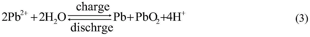
由方程式(3)可以看出充电时,如消耗1摩尔的Pb2+,就有2摩尔的H+生成,生成PbO2和Pb沉积层会增加电池的欧姆电阻,而生成H+会降低溶液电阻值,这样会导致通过电压无法准确的计算出活性物质PbO2和Pb的量,即充电电量。反之,放电时无法通过电压准确判断出单液流电池剩余电量。而通过标定正负极上生成沉积物PbO2和Pb所消耗Pb2+的量,虽然可以精确地得到单液流电池电量值,但这种检测方法耗时,无法实现单液流电池使用时实时快捷监控电量的功能。因此解决实时监控电池现有容量是保证电池正常运行的必要条件,有利于电池的维护管理、延长电池的使用寿命。It can be seen from equation (3) that when charging, if 1 mole of Pb 2+ is consumed, 2 moles of H + will be generated, and the formation of PbO 2 and Pb deposition will increase the ohmic resistance of the battery, while the generation of H + will reduce the solution Resistance value, this will lead to the inability to accurately calculate the amount of active materials PbO 2 and Pb through the voltage, that is, the charging capacity. On the contrary, the remaining power of the single-flow battery cannot be accurately judged by the voltage during discharge. By calibrating the amount of Pb 2+ consumed by the formation of deposits PbO 2 and Pb on the positive and negative electrodes, although the power value of the single flow battery can be accurately obtained, this detection method is time-consuming and cannot achieve The function of real-time and quick monitoring of power consumption. Therefore, solving the real-time monitoring of the existing capacity of the battery is a necessary condition to ensure the normal operation of the battery, which is beneficial to the maintenance and management of the battery and prolongs the service life of the battery.
发明内容Contents of the invention
本发明的目的是提供一种实时监控单液流电池电量的方法,具有电池的维护管理、延长电池的使用寿命的特点。The purpose of the present invention is to provide a method for real-time monitoring of the power of a single flow battery, which has the characteristics of battery maintenance and management and prolonging the service life of the battery.
本发明所采用的技术方案是,一种实时监控单液流电池电量的方法,具体按照以下步骤实施:The technical solution adopted in the present invention is a method for real-time monitoring of the power of a single-flow battery, which is specifically implemented according to the following steps:
步骤1、测定25℃下单液流电池的起始电解液电导率σ0 25℃;Step 1. Measure the initial electrolyte conductivity σ 0 25°C of the single flow battery at 25°C ;
步骤2、以第一预设电流I1进行恒流充电,充电过程中,记录不同充电时间t1、t2、t3……ti下的单液流电池电量Q1、Q2、Q3……Qi和相应的电解液的温度T1、T2、T3……Ti及电解液电导率
步骤3、线性拟合单液流电池电量Qi和相应的标准电解液电导率σi 25℃的线性关系式,并计算所述线性关系式的斜率α。Step 3. Linearly fitting the linear relationship between the electric quantity Q i of the single flow battery and the corresponding conductivity σ i of the standard electrolyte at 25°C , and calculating the slope α of the linear relationship.
本发明的特点还在于:The present invention is also characterized in that:
步骤3中线性关系式为:The linear relationship in step 3 is:
Qi=α×(σi 25℃-σ0 25℃) (1)Q i =α×(σ i 25°C -σ 0 25°C ) (1)
式中,α为斜率,σi 25℃为标准电解液电导率,σ0 25℃为起始电解液电导率。In the formula, α is the slope, σ i 25°C is the conductivity of the standard electrolyte, and σ 0 25°C is the conductivity of the initial electrolyte.
步骤2中in step 2
Qi=I1×ti (2)Q i =I 1 ×t i (2)
式中,ti为充电时间,I1为第一预设电流。In the formula, t i is the charging time, and I 1 is the first preset current.
步骤1中step 1
I1=J1×S (3)I 1 =J 1 ×S (3)
式中,S为电极板的面积,J1为电流密度10~30mA/cm2。In the formula, S is the area of the electrode plate, and J 1 is the current density of 10-30 mA/cm 2 .
步骤3中step 3

式中,β为25℃电解液电导率的温度补偿系数,Ti为电解液的温度,
步骤1中单液流单体电池电解液为甲基磺酸铅/甲基磺酸电解液、三氟甲基磺酸铅/三氟甲基磺酸电解液、氟硼酸铅/氟硼酸电解液、高氯酸铅/高氯酸电解液、氟硅酸铅/氟硅酸电解液其中一种电解液体系。In step 1, the single-flow monomer battery electrolyte is lead methanesulfonate/methanesulfonic acid electrolyte, lead trifluoromethanesulfonate/trifluoromethanesulfonic acid electrolyte, lead fluoroborate/fluoroboric acid electrolyte , Lead perchlorate/perchloric acid electrolyte, lead fluorosilicate/fluorosilicate electrolyte, one of the electrolyte systems.
本发明的有益效果是:The beneficial effects of the present invention are:
1、本发明的方法采用单液流电池电量与电解液电导率的线性关系,通过记录电解液电导率的变化能够准确的反映单液流电池的电量,即充电电量、额定电量、剩余电量及放电电量,方法准确可靠、方便简单、运行成本低。1. The method of the present invention adopts the linear relationship between the electric quantity of the single-flow battery and the conductivity of the electrolyte, and can accurately reflect the electric quantity of the single-flow battery by recording the change of the conductivity of the electrolyte, that is, the charging electric quantity, the rated electric quantity, the remaining electric quantity and The method of discharging electricity is accurate and reliable, convenient and simple, and has low operating cost.
2、通过检测电解液电导率实时监控单液流电池的容量变化,能够有效地防止单液流电池过充,及使用过程中出现馈电现象,保证单液流电池的正常使用,延长使用寿命。2. Real-time monitoring of the capacity change of the single-flow battery by detecting the conductivity of the electrolyte can effectively prevent the single-flow battery from being overcharged and feeding phenomenon during use, ensuring the normal use of the single-flow battery and prolonging the service life .
附图说明Description of drawings
图1是本发明一种单液流电池电量的实时监控方法的单液流电池容量与电解液电导率的线性关系图。Fig. 1 is a linear relationship diagram between the capacity of a single flow battery and the conductivity of an electrolyte in a method for real-time monitoring of the electric quantity of a single flow battery according to the present invention.
具体实施方式Detailed ways
下面结合附图和具体实施方式对本发明进行详细说明。The present invention will be described in detail below in conjunction with the accompanying drawings and specific embodiments.
本发明一种实时监控单液流电池电量的方法,具体按照以下步骤实施:The present invention is a method for real-time monitoring of the power of a single flow battery, which is specifically implemented according to the following steps:
步骤1、测定25℃下单液流电池的起始电解液电导率σ0 25℃;Step 1. Measure the initial electrolyte conductivity σ 0 25°C of the single flow battery at 25°C ;
步骤2、以第一预设电流I1进行恒流充电,充电过程中,记录不同充电时间t1、t2、t3……ti下的单液流电池电量Q1、Q2、Q3……Qi和相应的电解液的温度T1、T2、T3……Ti及电解液电导率
步骤3、线性拟合单液流电池电量Qi和相应的标准电解液电导率σi 25℃的线性关系式,并计算所述线性关系式的斜率α。Step 3. Linearly fitting the linear relationship between the electric quantity Q i of the single flow battery and the corresponding conductivity σ i of the standard electrolyte at 25°C , and calculating the slope α of the linear relationship.
步骤3中线性关系式为:The linear relationship in step 3 is:
Qi=α×(σi 25℃-σ0 25℃) (1)Q i =α×(σ i 25°C -σ 0 25°C ) (1)
式中,α值为图1中所示斜线的斜率,为常数;,σi 25℃为标准电解液电导率,σ0 25℃为起始电解液电导率。In the formula, α is the slope of the slope shown in Figure 1 and is a constant; σ i 25°C is the conductivity of the standard electrolyte, and σ 0 25°C is the conductivity of the initial electrolyte.
步骤2中in step 2
Qi=I1×ti (2)Q i =I 1 ×t i (2)
式中,ti为充电时间,I1为第一预设电流。In the formula, t i is the charging time, and I 1 is the first preset current.
步骤1中step 1
I1=J1×S (3)I 1 =J 1 ×S (3)
式中,S为电极板的面积,J1为电流密度10~30mA/cm2。In the formula, S is the area of the electrode plate, and J 1 is the current density of 10-30 mA/cm 2 .
步骤3中step 3

式中,β为25℃电解液电导率的温度补偿系数,Ti为电解液的温度,
步骤1中β是相对于25℃电解液电导率的温度补偿系数,针对不同的电解液体系及浓度配比其值不同,准确值需根据实际情况测得。一般情况下,甲基磺酸铅/甲基磺酸电解液β=0.03/℃、三氟甲基磺酸铅/三氟甲基磺酸电解液β=0.03/℃、氟硼酸铅/氟硼酸电解液β=0.02/℃、高氯酸铅/高氯酸电解液β=0.02/℃、氟硅酸铅/氟硅酸电解液β=0.02/℃。In step 1, β is the temperature compensation coefficient relative to the conductivity of the electrolyte at 25°C. Its value is different for different electrolyte systems and concentration ratios, and the exact value needs to be measured according to the actual situation. In general, lead methanesulfonate/methanesulfonic acid electrolyte β=0.03/℃, lead trifluoromethanesulfonate/trifluoromethanesulfonic acid electrolyte β=0.03/℃, lead fluoroborate/fluoroboric acid Electrolyte β=0.02/°C, lead perchlorate/perchloric acid electrolyte β=0.02/°C, lead fluorosilicate/fluorosilicate electrolyte β=0.02/°C.
为验证步骤3得到的线性关系式的适用范围与准确性,具体按照以下步骤验证:In order to verify the scope and accuracy of the linear relational formula obtained in step 3, follow the steps below to verify:
步骤a、充电至设定额定电量Qs后,在25℃下测定该设定额定电量下对应的标准电解液电导率σs 25℃,标准电解液电导率σs 25℃为单液流电池的截止电导率值。Step a. After charging to the set rated capacity Q s , measure the standard electrolyte conductivity σ s 25 °C corresponding to the set rated capacity at 25 °C, and the standard electrolyte conductivity σ s 25 °C is a single flow battery cut-off conductivity value.
步骤b、以第二预设电流I2进行恒流放电至单液流电池的放电截止电压,使单液流电池恢复到初始态;Step b, performing constant current discharge with the second preset current I2 to the discharge cut-off voltage of the single flow battery, so as to restore the single flow battery to the initial state;
步骤b中第二预设电流I2<I1,I2=J2×S,其中S为电极板的面积,J2为电流密度5~10mA/cm2;中截止电压Vf=1.0V×N,其中N为电堆中串联电对的数量。In step b, the second preset current I 2 <I 1 , I 2 =J 2 ×S, where S is the area of the electrode plate, J 2 is the current density of 5-10mA/cm 2 ; medium cut-off voltage V f =1.0V ×N, where N is the number of series electric pairs in the stack.
步骤c、进行单液流电池充放电使用;Step c, charging and discharging the single flow battery;
步骤c具体按照以下步骤实施:Step c is specifically implemented according to the following steps:
步骤c.1、以第一预设电流密度I1充电至电解液电导率达到截止电解液电导率值σs,根据式(1),通过实时监测的电解液电导率值可以得出即时单液流电池充电电量;Step c.1, charging with the first preset current density I 1 until the conductivity of the electrolyte reaches the cut-off value σ s of the electrolyte conductivity, according to the formula (1), the instant single Charging capacity of the flow battery;
步骤c.2、以第三预设电流密度I3恒流放电至截止电压Vf,根据式(1),通过实时监测的电解液电导率值可以得出即时单液流电池剩余电量;Step c.2, constant current discharge to the cut-off voltage V f with the third preset current density I 3 , according to formula (1), the remaining power of the instant single-flow battery can be obtained through the real-time monitoring of the electrolyte conductivity value;
步骤c中所述第三预设电流密度I3≤I1,I3=J3×S,其中S为电极板的面积,J3为电流密度10~20mA/cm2;The third preset current density I 3 ≤ I 1 in step c, I 3 =J 3 ×S, wherein S is the area of the electrode plate, J 3 is the current density of 10-20mA/cm 2 ;
步骤c中相应的标准电解液电导率σi 25℃,可通过将式(4)输入电导率测试仪可以自动进行温度补偿测得;The corresponding standard electrolyte conductivity σ i 25°C in step c can be measured by automatically performing temperature compensation by inputting formula (4) into the conductivity tester;
步骤c中截止电压Vf=1.0V×N,其中N为电堆中串联电对的数量。In step c, the cut-off voltage V f =1.0V×N, where N is the number of series electric pairs in the electric stack.
步骤c中恒流充电和恒流放电为单液流电池一般充放电规则,通过测试电解液电导率来监控单液流电池的电量的方法同时适用于单液流电池其它充放电规则。The constant current charging and constant current discharging in step c are general charge and discharge rules for single flow batteries, and the method of monitoring the power of single flow batteries by testing the conductivity of the electrolyte is also applicable to other charge and discharge rules for single flow batteries.
对单液流电池进行电量监控测试,通过标定电解液中Pb2+的摩尔量,从而得到所消耗Pb2+的摩尔量来计算得到单液流电池的实际电量。采用测定电解液电导率的方法所得的单液流电池电量误差小于1%。The power monitoring test of the single-flow battery is carried out, and the actual power of the single-flow battery is calculated by the molar amount of Pb 2+ consumed by calibrating the molar amount of Pb 2+ in the electrolyte. The error of the electric quantity of the single flow battery obtained by measuring the conductivity of the electrolyte is less than 1%.
实施例1Example 1
一种1kW/4kWh单液流电池,由电堆(由30个电对串联组成)、电解液和循环系统(动力泵)组成,采用甲基磺酸铅/甲基磺酸电解液体系,其中电池的正负极均为碳聚合物导电板,面积为32×25=800cm2,甲基磺酸铅和甲基磺酸的摩尔浓度比为1.0:1.0,电解液体积为240L。A 1kW/4kWh single-fluid flow battery, consisting of a stack (composed of 30 pairs in series), an electrolyte and a circulation system (power pump), using a lead methanesulfonate/methanesulfonic acid electrolyte system, in which The positive and negative electrodes of the battery are carbon polymer conductive plates with an area of 32×25=800cm 2 , the molar concentration ratio of lead methanesulfonate and methanesulfonic acid is 1.0:1.0, and the volume of electrolyte is 240L.
本发明一种实时监控单液流电池电量的方法,具体按照以下步骤实施:The present invention is a method for real-time monitoring of the power of a single flow battery, which is specifically implemented according to the following steps:
步骤1、测定25℃下单液流电池的起始电解液电导率σ0 25℃=285mS/cm;Step 1. Measure the initial electrolyte conductivity σ 0 25°C = 285mS/cm of the single flow battery at 25°C;
步骤2、以第一预设电流I1=24A进行恒流充电,充电过程中,记录不同充电时间t1、t2、t3……ti下的单液流电池电量Q1、Q2、Q3……Qi和相应的电解液的温度T1、T2、T3……Ti及电解液电导率
步骤3、线性拟合单液流电池电量Qi和相应的标准电解液电导率σi 25℃的线性关系式,并计算所述线性关系式的斜率α。Step 3. Linearly fitting the linear relationship between the electric quantity Q i of the single flow battery and the corresponding conductivity σ i of the standard electrolyte at 25°C , and calculating the slope α of the linear relationship.
步骤1中step 1
I1=J1×S=30mA/cm2×800cm2=24A (3)I 1 =J 1 ×S = 30mA/cm 2 ×800cm 2 =24A (3)
式中,电极板的面积S为800cm2,电流密度J1为30mA/cm2。In the formula, the area S of the electrode plate is 800 cm 2 , and the current density J 1 is 30 mA/cm 2 .
步骤2中in step 2
Qi=I1×ti=24A×ti (2)Q i =I 1 ×t i =24A×t i (2)
式中,ti为充电时间,I1为第一预设电流。In the formula, t i is the charging time, and I 1 is the first preset current.
步骤3中step 3

式中,β为25℃电解液电导率的温度补偿系数,Ti为电解液的温度,
步骤3中线性关系式为:The linear relationship in step 3 is:

式中,α值为图1中所示斜线的斜率,为常数;,σi 25℃为标准电解液电导率,σ0 25℃为起始电解液电导率;In the formula, α is the slope of the slope shown in Figure 1, which is a constant; σ i 25°C is the conductivity of the standard electrolyte, and σ 0 25°C is the conductivity of the initial electrolyte;
式(1)与式(2)合并,得Combining formula (1) and formula (2), we get

将ti对应的Ti与
为验证步骤3得到的线性关系式的适用范围与准确性,具体按照以下步骤验证:In order to verify the scope and accuracy of the linear relational formula obtained in step 3, follow the steps below to verify:
步骤a、充电至设定额定电量4kWh后,在25℃下测定该设定额定电量下对应的标准电解液电导率389mS/cm,该电导率值为单液流电池的截止电导率值;Step a. After charging to the set rated power of 4kWh, measure the conductivity of the standard electrolyte corresponding to the set rated power at 25°C, which is 389mS/cm, and the conductivity value is the cut-off conductivity value of the single flow battery;
步骤b、以第二预设电流8A(放电电流密度10mA/cm2,10mA/cm2×800cm2=8A)进行恒流放电至单液流电池的放电截止电压30V(Vf=1.0V×30=30V);Step b. Carry out constant current discharge with the second preset current of 8A (discharge current density 10mA/cm 2 , 10mA/cm 2 ×800cm 2 =8A) until the discharge cut-off voltage of the single flow battery is 30V (V f =1.0V× 30=30V);
步骤b中第二预设电流I2<I1,I2=J2×S,其中S为电极板的面积,J2为电流密度10mA/cm2;中截止电压Vf=1.0V×N,其中N为电堆中串联电对的数量。In step b, the second preset current I 2 <I 1 , I 2 =J 2 ×S, where S is the area of the electrode plate, J 2 is the current density 10mA/cm 2 ; medium cut-off voltage V f =1.0V×N , where N is the number of series electric pairs in the stack.
步骤c.1、以第一预设电流24A进行恒流充电(充电电流密度30mA/cm2,30mA/cm2×800cm2=24A),直至电解液电导率达到截止标准电解液电导率值389mS/cm,根据式(1),通过实时监测的电解液电导率值可以得出即时单液流电池充电电量;Step c.1, carry out constant current charging with the first preset current 24A (charging current density 30mA/cm 2 , 30mA/cm 2 ×800cm 2 =24A), until the conductivity of the electrolyte reaches the cut-off standard electrolyte conductivity value of 389mS /cm, according to formula (1), the real-time charging capacity of the single-flow battery can be obtained through the real-time monitoring of the electrolyte conductivity value;
步骤c.2、以第三预设电流16A(放电电流密度20mA/cm2,20mA/cm2×800cm2=16A)恒流放电至截止电压30V(Vf=1.0V×30=30V),根据式(1),通过实时监测的电解液电导率值可以得出即时单液流电池剩余电量;Step c.2. Discharge at a constant current of the third preset current 16A (discharge current density 20mA/cm 2 , 20mA/cm 2 ×800cm 2 =16A) to a cut-off voltage of 30V (V f =1.0V×30=30V), According to formula (1), the remaining power of the instant single-flow battery can be obtained through the real-time monitoring of the electrolyte conductivity value;
步骤c中所述第三预设电流密度I3≤I1,I3=J3×S,其中S为电极板的面积,J3为电流密度20mA/cm2;The third preset current density in step c is I 3 ≤ I 1 , I 3 =J 3 ×S, where S is the area of the electrode plate, and J 3 is the current density of 20mA/cm 2 ;
步骤c中相应的标准电解液电导率σi 25℃,可通过将式(4)输入电导率测试仪可以自动进行温度补偿测得;The corresponding standard electrolyte conductivity σ i 25°C in step c can be measured by automatically performing temperature compensation by inputting formula (4) into the conductivity tester;
步骤c中截止电压Vf=1.0V×N,其中N为电堆中串联电对的数量。In step c, the cut-off voltage V f =1.0V×N, where N is the number of series electric pairs in the electric stack.
对单液流电池进行电量监控测试,采用测定电解液电导率的方法所得的单液流电池电量误差为0.35%。The power monitoring test of the single-flow battery was carried out, and the error of the power of the single-flow battery obtained by measuring the conductivity of the electrolyte was 0.35%.
实施例2Example 2
一种1kW/4kWh单液流电池,由电堆(由30个电对串联组成)、电解液和循环系统(动力泵)组成,采用三氟甲基磺酸铅/三氟甲基磺酸电解液体系,其中电池的正负极均为碳聚合物导电板,面积为32×25=800cm2,三氟甲基磺酸铅和三氟甲基磺酸的摩尔浓度比为1.0:1.0,电解液体积为240L.A 1kW/4kWh single-flow battery consisting of a stack (composed of 30 pairs in series), electrolyte and circulation system (power pump), using lead trifluoromethanesulfonate/trifluoromethanesulfonic acid electrolysis Liquid system, in which the positive and negative electrodes of the battery are carbon polymer conductive plates, the area is 32×25=800cm 2 , the molar concentration ratio of lead trifluoromethanesulfonate and trifluoromethanesulfonic acid is 1.0:1.0, electrolytic The liquid volume is 240L.
本发明一种实时监控单液流电池电量的方法,具体按照以下步骤实施:The present invention is a method for real-time monitoring of the power of a single flow battery, which is specifically implemented according to the following steps:
步骤1、测定25℃下单液流电池的起始电解液电导率σ0 25℃=298mS/cm;Step 1. Measure the initial electrolyte conductivity σ 0 25°C = 298mS/cm of the single flow battery at 25°C;
步骤2、以第一预设电流I1=16A进行恒流充电,充电过程中,记录不同充电时间t1、t2、t3……ti下的单液流电池电量Q1、Q2、Q3……Qi和相应的电解液的温度T1、T2、T3……Ti及电解液电导率
步骤3、线性拟合单液流电池电量Qi和相应的标准电解液电导率σi 25℃的线性关系式,并计算所述线性关系式的斜率α。Step 3. Linearly fitting the linear relationship between the electric quantity Q i of the single flow battery and the corresponding conductivity σ i of the standard electrolyte at 25°C , and calculating the slope α of the linear relationship.
步骤1中step 1
I1=J1×S=20mA/cm2×800cm2=16A (3)I 1 =J 1 ×S = 20mA/cm 2 ×800cm 2 =16A (3)
式中,电极板的面积S为800cm2,电流密度J1为20mA/cm2。In the formula, the area S of the electrode plate is 800 cm 2 , and the current density J 1 is 20 mA/cm 2 .
步骤2中in step 2
Qi=I1×ti=16A×ti (2)Q i =I 1 ×t i =16A×t i (2)
式中,ti为充电时间,I1为第一预设电流。In the formula, t i is the charging time, and I 1 is the first preset current.
步骤3中step 3

式中,β为25℃电解液电导率的温度补偿系数,Ti为电解液的温度,
步骤3中线性关系式为:The linear relationship in step 3 is:

式中,α值为图1中所示斜线的斜率,为常数;,σi 25℃为标准电解液电导率,σ0 25℃为起始电解液电导率;In the formula, α is the slope of the slope shown in Figure 1, which is a constant; σ i 25°C is the conductivity of the standard electrolyte, and σ 0 25°C is the conductivity of the initial electrolyte;
式(1)与式(2)合并,得Combining formula (1) and formula (2), we get

将ti对应的Ti与
为验证步骤3得到的线性关系式的适用范围与准确性,具体按照以下步骤验证:In order to verify the scope and accuracy of the linear relational formula obtained in step 3, follow the steps below to verify:
步骤a、充电至设定额定电量4kWh后,在25℃下测定该设定额定电量下对应的标准电解液电导率346mS/cm,该电导率值为单液流电池的截止电导率值;Step a. After charging to the set rated power of 4kWh, measure the conductivity of the standard electrolyte corresponding to the set rated power at 25°C, which is 346mS/cm, and this conductivity value is the cut-off conductivity value of the single flow battery;
步骤b、以第二预设电流8A(放电电流密度10mA/cm2,10mA/cm2×800cm2=8A)进行恒流放电至单液流电池的放电截止电压30V(Vf=1.0V×30=30V);Step b. Carry out constant current discharge with the second preset current of 8A (discharge current density 10mA/cm 2 , 10mA/cm 2 ×800cm 2 =8A) until the discharge cut-off voltage of the single flow battery is 30V (V f =1.0V× 30=30V);
步骤b中第二预设电流I2<I1,I2=J2×S,其中S为电极板的面积,J2为电流密度10mA/cm2;中截止电压Vf=1.0V×N,其中N为电堆中串联电对的数量。In step b, the second preset current I 2 <I 1 , I 2 =J 2 ×S, where S is the area of the electrode plate, J 2 is the current density 10mA/cm 2 ; medium cut-off voltage V f =1.0V×N , where N is the number of series electric pairs in the stack.
步骤c.1、以第一预设电流16A进行恒流充电(充电电流密度30mA/cm2,30mA/cm2×800cm2=16A),直至电解液电导率达到截止电解液电导率值298mS/cm,根据式(1),通过实时监测的电解液电导率值可以得出即时单液流电池充电电量;Step c.1. Carry out constant current charging with the first preset current of 16A (charging current density 30mA/cm 2 , 30mA/cm 2 ×800cm 2 = 16A), until the conductivity of the electrolyte reaches the cut-off value of 298mS/ cm, according to formula (1), the real-time charging capacity of the single-flow battery can be obtained through the real-time monitoring of the electrolyte conductivity value;
步骤c.2、以第三预设电流16A(放电电流密度20mA/cm2,20mA/cm2×800cm2=16A)恒流放电至截止电压30V(Vf=1.0V×30=30V),根据式(1),通过实时监测的电解液电导率值可以得出即时单液流电池剩余电量;Step c.2. Discharge at a constant current of the third preset current 16A (discharge current density 20mA/cm 2 , 20mA/cm 2 ×800cm 2 =16A) to a cut-off voltage of 30V (V f =1.0V×30=30V), According to formula (1), the remaining power of the instant single-flow battery can be obtained through the real-time monitoring of the electrolyte conductivity value;
步骤c中所述第三预设电流密度I3≤I1,I3=J3×S,其中S为电极板的面积,J3为电流密度20mA/cm2;The third preset current density in step c is I 3 ≤ I 1 , I 3 =J 3 ×S, where S is the area of the electrode plate, and J 3 is the current density of 20mA/cm 2 ;
步骤c中相应的标准电解液电导率σi 25℃,可通过将式(4)输入电导率测试仪可以自动进行温度补偿测得;The corresponding standard electrolyte conductivity σ i 25°C in step c can be measured by automatically performing temperature compensation by inputting formula (4) into the conductivity tester;
步骤c中截止电压Vf=1.0V×N,其中N为电堆中串联电对的数量。In step c, the cut-off voltage V f =1.0V×N, where N is the number of series electric pairs in the electric stack.
对单液流电池进行电量监控测试,采用测定电解液电导率的方法所得的单液流电池电量误差为0.56%。The power monitoring test of the single-flow battery was carried out, and the error of the power of the single-flow battery obtained by measuring the conductivity of the electrolyte was 0.56%.
实施例3Example 3
一种500W/5kWh单液流电池,由电堆(由42个电对串联组成)、电解液和循环系统(动力泵)组成,采用氟硼酸铅/氟硼酸电解液体系,其中电池的正负极均为碳聚合物导电板,面积为32×25=800cm2,氟硼酸铅和氟硼酸的摩尔浓度比为2.5:0.3,电解液体积为84L。A 500W/5kWh single-fluid flow battery, consisting of a stack (composed of 42 pairs in series), electrolyte and circulation system (power pump), using lead fluoroborate/fluoroboric acid electrolyte system, in which the positive and negative of the battery The poles are all carbon polymer conductive plates with an area of 32×25=800cm 2 , the molar concentration ratio of lead fluoroborate and fluoroboric acid is 2.5:0.3, and the volume of electrolyte is 84L.
本发明一种实时监控单液流电池电量的方法,具体按照以下步骤实施:The present invention is a method for real-time monitoring of the power of a single flow battery, which is specifically implemented according to the following steps:
步骤1、测定25℃下单液流电池的起始电解液电导率σ0 25℃=105mS/cm;Step 1. Measure the initial electrolyte conductivity σ 0 25°C = 105mS/cm of the single flow battery at 25°C;
步骤2、以第一预设电流I1=16A进行恒流充电,充电过程中,记录不同充电时间t1、t2、t3……ti下的单液流电池电量Q1、Q2、Q3……Qi和相应的电解液的温度T1、T2、T3……Ti及电解液电导率
步骤3、线性拟合单液流电池电量Qi和相应的标准电解液电导率σi 25℃的线性关系式,并计算所述线性关系式的斜率α。Step 3. Linearly fitting the linear relationship between the electric quantity Q i of the single flow battery and the corresponding conductivity σ i of the standard electrolyte at 25°C , and calculating the slope α of the linear relationship.
步骤1中step 1
I1=J1×S=10mA/cm2×800cm2=8A (3)I 1 =J 1 ×S = 10mA/cm 2 ×800cm 2 =8A (3)
式中,电极板的面积S为800cm2,电流密度J1为10mA/cm2。In the formula, the area S of the electrode plate is 800 cm 2 , and the current density J 1 is 10 mA/cm 2 .
步骤2中in step 2
Qi=I1×ti=8A×ti (2)Q i =I 1 ×t i =8A×t i (2)
式中,ti为充电时间,I1为第一预设电流。In the formula, t i is the charging time, and I 1 is the first preset current.
步骤3中step 3

式中,β为25℃电解液电导率的温度补偿系数,Ti为电解液的温度,
步骤3中线性关系式为:The linear relationship in step 3 is:

式中,α值为图1中所示斜线的斜率,为常数;,σi 25℃为标准电解液电导率,σ0 25℃为起始电解液电导率;In the formula, α is the slope of the slope shown in Figure 1, which is a constant; σ i 25°C is the conductivity of the standard electrolyte, and σ 0 25°C is the conductivity of the initial electrolyte;
式(1)与式(2)合并,得Combining formula (1) and formula (2), we get

将ti对应的Ti与
为验证步骤3得到的线性关系式的适用范围与准确性,具体按照以下步骤验证:In order to verify the scope and accuracy of the linear relational formula obtained in step 3, follow the steps below to verify:
步骤a、充电至设定额定电量5kWh后,在25℃下测定该设定额定电量下对应的标准电解液电导率356mS/cm,该电导率值为单液流电池的截止电导率值;Step a. After charging to the set rated power of 5kWh, measure the conductivity of the standard electrolyte corresponding to the set rated power at 25°C, which is 356mS/cm, and the conductivity value is the cut-off conductivity value of the single flow battery;
步骤b、以第二预设电流4A(放电电流密度5mA/cm2,5mA/cm2×800cm2=4A)进行恒流放电至单液流电池的放电截止电压42V(Vf=1.0V×42=42V);Step b. Perform constant current discharge with the second preset current of 4A (discharge current density 5mA/cm 2 , 5mA/cm 2 ×800cm 2 =4A) to the discharge cut-off voltage of the single flow battery 42V (V f =1.0V× 42=42V);
步骤b中第二预设电流I2<I1,I2=J2×S,其中S为电极板的面积,J2为电流密度10mA/cm2;中截止电压Vf=1.0V×N,其中N为电堆中串联电对的数量。In step b, the second preset current I 2 <I 1 , I 2 =J 2 ×S, where S is the area of the electrode plate, J 2 is the current density 10mA/cm 2 ; medium cut-off voltage V f =1.0V×N , where N is the number of series electric pairs in the stack.
步骤c.1、以第一预设电流8A进行恒流充电(充电电流密度10mA/cm2,10mA/cm2×800cm2=8A),直至电解液电导率达到截止标准电解液电导率值356mS/cm,根据式(1),通过实时监测的电解液电导率值可以得出即时单液流电池充电电量;Step c.1, carry out constant current charging with the first preset current 8A (charging current density 10mA/cm 2 , 10mA/cm 2 ×800cm 2 =8A), until the conductivity of the electrolyte reaches the cut-off standard electrolyte conductivity value of 356mS /cm, according to formula (1), the real-time charging capacity of the single-flow battery can be obtained through the real-time monitoring of the electrolyte conductivity value;
步骤c.2、以第三预设电流8A(放电电流密度10mA/cm2,10mA/cm2×800cm2=8A)恒流放电至截止电压42V(Vf=1.0V×42=42V),根据式(1),通过实时监测的电解液电导率值可以得出即时单液流电池剩余电量;Step c.2: Discharge at a constant current of a third preset current of 8A (discharge current density 10mA/cm 2 , 10mA/cm 2 ×800cm 2 =8A) to a cut-off voltage of 42V (V f =1.0V×42=42V), According to formula (1), the remaining power of the instant single-flow battery can be obtained through the real-time monitoring of the electrolyte conductivity value;
步骤c中第三预设电流密度I3≤I1,I3=J3×S,其中S为电极板的面积,J3为电流密度10mA/cm2;In step c, the third preset current density I 3 ≤ I 1 , I 3 =J 3 ×S, where S is the area of the electrode plate, and J 3 is the current density of 10mA/cm 2 ;
步骤c中相应的标准电解液电导率σi 25℃,可通过将式(4)输入电导率测试仪可以自动进行温度补偿测得;The corresponding standard electrolyte conductivity σ i 25°C in step c can be measured by automatically performing temperature compensation by inputting formula (4) into the conductivity tester;
步骤c中截止电压Vf=1.0V×N,其中N为电堆中串联电对的数量。In step c, the cut-off voltage V f =1.0V×N, where N is the number of series electric pairs in the electric stack.
对单液流电池进行电量监控测试,采用测定电解液电导率的方法所得的单液流电池电量误差为0.72%。The power monitoring test of the single-flow battery was carried out, and the error of the power of the single-flow battery obtained by measuring the conductivity of the electrolyte was 0.72%.
实施例4Example 4
一种500W/2kWh单液流电池,由电堆(由42个电对串联组成)、电解液和循环系统(动力泵)组成,采用甲基磺酸铅/甲基磺酸电解液体系,其中电池的正负极均为碳聚合物导电板,面积为32×25=800cm2,甲基磺酸铅和甲基磺酸的摩尔浓度比为1.8:0.3,电解液体积为120L。A 500W/2kWh single-flow battery, consisting of a stack (composed of 42 pairs in series), an electrolyte and a circulation system (power pump), using a lead methanesulfonate/methanesulfonic acid electrolyte system, wherein The positive and negative electrodes of the battery are carbon polymer conductive plates with an area of 32×25=800cm 2 , the molar concentration ratio of lead methanesulfonate and methanesulfonic acid is 1.8:0.3, and the volume of electrolyte is 120L.
本发明一种实时监控单液流电池电量的方法,具体按照以下步骤实施:The present invention is a method for real-time monitoring of the power of a single flow battery, which is specifically implemented according to the following steps:
步骤1、测定25℃下单液流电池的起始电解液电导率σ0 25℃=96mS/cm;Step 1. Measure the initial electrolyte conductivity σ 0 25°C = 96mS/cm of the single flow battery at 25°C;
步骤2、以第一预设电流I1=8A进行恒流充电,充电过程中,记录不同充电时间t1、t2、t3……ti下的单液流电池电量Q1、Q2、Q3……Qi和相应的电解液的温度T1、T2、T3……Ti及电解液电导率
步骤3、线性拟合单液流电池电量Qi和相应的标准电解液电导率σi 25℃的线性关系式,并计算所述线性关系式的斜率α。Step 3. Linearly fitting the linear relationship between the electric quantity Q i of the single flow battery and the corresponding conductivity σ i of the standard electrolyte at 25°C , and calculating the slope α of the linear relationship.
步骤1中step 1
I1=J1×S=10mA/cm2×800cm2=8A (3)I 1 =J 1 ×S = 10mA/cm 2 ×800cm 2 =8A (3)
式中,电极板的面积S为800cm2,电流密度J1为10mA/cm2。In the formula, the area S of the electrode plate is 800 cm 2 , and the current density J 1 is 10 mA/cm 2 .
步骤2中in step 2
Qi=I1×ti=8A×ti (2)Q i =I 1 ×t i =8A×t i (2)
式中,ti为充电时间,I1为第一预设电流。In the formula, t i is the charging time, and I 1 is the first preset current.
步骤3中step 3

式中,β为25℃电解液电导率的温度补偿系数,Ti为电解液的温度,
步骤3中线性关系式为:The linear relationship in step 3 is:

式中,α值为图1中所示斜线的斜率,为常数;σi 25℃为标准电解液电导率,σ0 25℃为起始电解液电导率;In the formula, α is the slope of the slope shown in Figure 1, which is a constant; σ i 25°C is the conductivity of the standard electrolyte, and σ 0 25°C is the conductivity of the initial electrolyte;
式(1)与式(2)合并,得Combining formula (1) and formula (2), we get

将ti对应的Ti与
为验证步骤3得到的线性关系式的适用范围与准确性,具体按照以下步骤验证:In order to verify the scope and accuracy of the linear relational formula obtained in step 3, follow the steps below to verify:
步骤a、充电至设定额定电量5kWh后,在25℃下测定该设定额定电量下对应的标准电解液电导率356mS/cm,该电导率值为单液流电池的截止电导率值;Step a. After charging to the set rated power of 5kWh, measure the conductivity of the standard electrolyte corresponding to the set rated power at 25°C, which is 356mS/cm, and the conductivity value is the cut-off conductivity value of the single flow battery;
步骤b、以第二预设电流4A(放电电流密度5mA/cm2,5mA/cm2×800cm2=4A)进行恒流放电至单液流电池的放电截止电压42V(Vf=1.0V×42=42V);Step b. Perform constant current discharge with the second preset current of 4A (discharge current density 5mA/cm 2 , 5mA/cm 2 ×800cm 2 =4A) to the discharge cut-off voltage of the single flow battery 42V (V f =1.0V× 42=42V);
步骤b中第二预设电流I2<I1,I2=J2×S,其中S为电极板的面积,J2为电流密度10mA/cm2;中截止电压Vf=1.0V×N,其中N为电堆中串联电对的数量。In step b, the second preset current I 2 <I 1 , I 2 =J 2 ×S, where S is the area of the electrode plate, J 2 is the current density 10mA/cm 2 ; medium cut-off voltage V f =1.0V×N , where N is the number of series electric pairs in the stack.
步骤c.1、以第一预设电流8A进行恒流充电(充电电流密度10mA/cm2,10mA/cm2×800cm2=8A),直至电解液电导率达到截止电解液电导率值356mS/cm,根据式(1),通过实时监测的电解液电导率值可以得出即时单液流电池充电电量;Step c.1. Carry out constant current charging with the first preset current of 8A (charging current density 10mA/cm 2 , 10mA/cm 2 ×800cm 2 =8A), until the conductivity of the electrolyte reaches the cut-off value of 356mS/ cm, according to formula (1), the real-time charging capacity of the single-flow battery can be obtained through the real-time monitoring of the electrolyte conductivity value;
步骤c.2、以第三预设电流8A(放电电流密度10mA/cm2,10mA/cm2×800cm2=8A)恒流放电至截止电压42V(Vf=1.0V×42=42V),根据式(1),通过实时监测的电解液电导率值可以得出即时单液流电池剩余电量;Step c.2: Discharge at a constant current of a third preset current of 8A (discharge current density 10mA/cm 2 , 10mA/cm 2 ×800cm 2 =8A) to a cut-off voltage of 42V (V f =1.0V×42=42V), According to formula (1), the remaining power of the instant single-flow battery can be obtained through the real-time monitoring of the electrolyte conductivity value;
步骤c中相应的标准电解液电导率σi 25℃,可通过将式(4)输入电导率测试仪可以自动进行温度补偿测得;The corresponding standard electrolyte conductivity σ i 25°C in step c can be measured by automatically performing temperature compensation by inputting formula (4) into the conductivity tester;
步骤c中第三预设电流密度I3≤I1,I3=J3×S,其中S为电极板的面积,J3为电流密度10mA/cm2;In step c, the third preset current density I 3 ≤ I 1 , I 3 =J 3 ×S, where S is the area of the electrode plate, and J 3 is the current density of 10mA/cm 2 ;
步骤c中截止电压Vf=1.0V×N,其中N为电堆中串联电对的数量。In step c, the cut-off voltage V f =1.0V×N, where N is the number of series electric pairs in the electric stack.
对单液流电池进行电量监控测试,采用测定电解液电导率的方法所得的单液流电池电量误差为0.59%。The power monitoring test of the single-flow battery was carried out, and the error of the power of the single-flow battery obtained by measuring the conductivity of the electrolyte was 0.59%.
实施例5Example 5
一种500W/2kWh单液流电池,由电堆(由42个电对串联组成)、电解液和循环系统(动力泵)组成,采用三氟甲基磺酸铅/三氟甲基磺酸电解液体系,其中电池的正负极均为碳聚合物导电板,面积为32×25=800cm2,三氟甲基磺酸铅和三氟甲基磺酸的摩尔浓度比为1.8:0.3,电解液体积为120L。A 500W/2kWh single-flow battery, consisting of a stack (composed of 42 pairs in series), electrolyte and circulation system (power pump), using lead trifluoromethanesulfonate/trifluoromethanesulfonic acid electrolysis Liquid system, in which the positive and negative electrodes of the battery are carbon polymer conductive plates, the area is 32×25=800cm 2 , the molar concentration ratio of lead trifluoromethanesulfonate and trifluoromethanesulfonic acid is 1.8:0.3, electrolytic The liquid volume is 120L.
本发明一种实时监控单液流电池电量的方法,具体按照以下步骤实施:The present invention is a method for real-time monitoring of the power of a single flow battery, which is specifically implemented according to the following steps:
步骤1、测定25℃下单液流电池的起始电解液电导率σ0 25℃=99mS/cm;Step 1. Measure the initial electrolyte conductivity σ 0 25°C = 99mS/cm of the single flow battery at 25°C;
步骤2、以第一预设电流I1=12A进行恒流充电,充电过程中,记录不同充电时间t1、t2、t3……ti下的单液流电池电量Q1、Q2、Q3……Qi和相应的电解液的温度T1、T2、T3……Ti及电解液电导率
步骤3、线性拟合单液流电池电量Qi和相应的标准电解液电导率σi 25℃的线性关系式,并计算所述线性关系式的斜率α。Step 3. Linearly fitting the linear relationship between the electric quantity Q i of the single flow battery and the corresponding conductivity σ i of the standard electrolyte at 25°C , and calculating the slope α of the linear relationship.
步骤1中step 1
I1=J1×S=30mA/cm2×800cm2=12A (3)I 1 =J 1 ×S=30mA/cm 2 ×800cm 2 =12A (3)
式中,电极板的面积S为800cm2,电流密度J1为15mA/cm2。In the formula, the area S of the electrode plate is 800 cm 2 , and the current density J 1 is 15 mA/cm 2 .
步骤2中in step 2
Qi=I1×ti=15A×ti (2)Q i =I 1 ×t i =15A×t i (2)
式中,ti为充电时间,I1为第一预设电流。In the formula, t i is the charging time, and I 1 is the first preset current.
步骤3中step 3

式中,β为25℃电解液电导率的温度补偿系数,Ti为电解液的温度,
步骤3中线性关系式为:The linear relationship in step 3 is:

式中,α值为图1中所示斜线的斜率,为常数;,σi 25℃为标准电解液电导率,σ0 25℃为起始电解液电导率;In the formula, α is the slope of the slope shown in Figure 1, which is a constant; σ i 25°C is the conductivity of the standard electrolyte, and σ 0 25°C is the conductivity of the initial electrolyte;
式(1)与式(2)合并,得Combining formula (1) and formula (2), we get

将ti对应的Ti与
为验证步骤3得到的线性关系式的适用范围与准确性,具体按照以下步骤验证:In order to verify the scope and accuracy of the linear relational formula obtained in step 3, follow the steps below to verify:
步骤a、充电至设定额定电量2kWh后,在25℃下测定该设定额定电量下对应的标准电解液电导率241mS/cm,该电导率值为单液流电池的截止电导率值;Step a. After charging to the set rated power of 2kWh, measure the conductivity of the standard electrolyte corresponding to the set rated power at 25°C, which is 241mS/cm, and this conductivity value is the cut-off conductivity value of the single flow battery;
步骤b、以第二预设电流8A(放电电流密度10mA/cm2,10mA/cm2×800cm2=8A)进行恒流放电至单液流电池的放电截止电压42V(Vf=1.0V×42=42V);Step b. Carry out constant current discharge with the second preset current of 8A (discharge current density 10mA/cm 2 , 10mA/cm 2 ×800cm 2 =8A) to the discharge cut-off voltage of the single flow battery of 42V (V f =1.0V× 42=42V);
步骤b中第二预设电流I2<I1,I2=J2×S,其中S为电极板的面积,J2为电流密度10mA/cm2;中截止电压Vf=1.0V×N,其中N为电堆中串联电对的数量。In step b, the second preset current I 2 <I 1 , I 2 =J 2 ×S, where S is the area of the electrode plate, J 2 is the current density 10mA/cm 2 ; medium cut-off voltage V f =1.0V×N , where N is the number of series electric pairs in the stack.
步骤c.1、以第一预设电流16A进行恒流充电(充电电流密度20mA/cm2,20mA/cm2×800cm2=16A),直至电解液电导率达到截止电解液电导率值241mS/cm,根据式(1),通过实时监测的电解液电导率值可以得出即时单液流电池充电电量;Step c.1. Carry out constant current charging with the first preset current of 16A (charging current density 20mA/cm 2 , 20mA/cm 2 ×800cm 2 = 16A), until the conductivity of the electrolyte reaches the cut-off value of 241mS/ cm, according to formula (1), the real-time charging capacity of the single-flow battery can be obtained through the real-time monitoring of the electrolyte conductivity value;
步骤c.2、以第三预设电流8A(放电电流密度10mA/cm2,10mA/cm2×800cm2=8A)恒流放电至截止电压42V(Vf=1.0V×42=42V),根据式(1),通过实时监测的电解液电导率值可以得出即时单液流电池剩余电量;Step c.2: Discharge at a constant current of a third preset current of 8A (discharge current density 10mA/cm 2 , 10mA/cm 2 ×800cm 2 =8A) to a cut-off voltage of 42V (V f =1.0V×42=42V), According to formula (1), the remaining power of the instant single-flow battery can be obtained through the real-time monitoring of the electrolyte conductivity value;
步骤c中第三预设电流密度I3≤I1,I3=J3×S,其中S为电极板的面积,J3为电流密度10mA/cm2;In step c, the third preset current density I 3 ≤ I 1 , I 3 =J 3 ×S, where S is the area of the electrode plate, and J 3 is the current density of 10mA/cm 2 ;
步骤c中相应的标准电解液电导率σi 25℃,可通过将式(4)输入电导率测试仪可以自动进行温度补偿测得;The corresponding standard electrolyte conductivity σ i 25°C in step c can be measured by automatically performing temperature compensation by inputting formula (4) into the conductivity tester;
步骤c中截止电压Vf=1.0V×N,其中N为电堆中串联电对的数量。In step c, the cut-off voltage V f =1.0V×N, where N is the number of series electric pairs in the electric stack.
对单液流电池进行电量监控测试,采用测定电解液电导率的方法所得的单液流电池电量误差为0.43%。The power monitoring test of the single-flow battery was carried out, and the error of the power of the single-flow battery obtained by measuring the conductivity of the electrolyte was 0.43%.
Claims (2)


Priority Applications (1)
| Application Number | Priority Date | Filing Date | Title |
|---|---|---|---|
| CN202010071200.1A CN111261905B (en) | 2020-01-21 | 2020-01-21 | A real-time monitoring method of single-flow battery power |
Applications Claiming Priority (1)
| Application Number | Priority Date | Filing Date | Title |
|---|---|---|---|
| CN202010071200.1A CN111261905B (en) | 2020-01-21 | 2020-01-21 | A real-time monitoring method of single-flow battery power |
Publications (2)
| Publication Number | Publication Date |
|---|---|
| CN111261905A CN111261905A (en) | 2020-06-09 |
| CN111261905B true CN111261905B (en) | 2023-03-14 |
Family
ID=70950974
Family Applications (1)
| Application Number | Title | Priority Date | Filing Date |
|---|---|---|---|
| CN202010071200.1A Active CN111261905B (en) | 2020-01-21 | 2020-01-21 | A real-time monitoring method of single-flow battery power |
Country Status (1)
| Country | Link |
|---|---|
| CN (1) | CN111261905B (en) |
Citations (5)
| Publication number | Priority date | Publication date | Assignee | Title |
|---|---|---|---|---|
| JPH07192748A (en) * | 1993-12-24 | 1995-07-28 | Agency Of Ind Science & Technol | Electrolyte flow-through type cell |
| JP2003007354A (en) * | 2001-06-25 | 2003-01-10 | Toyota Motor Corp | Method and apparatus for evaluating characteristics of lithium secondary battery |
| CN101354432A (en) * | 2007-07-23 | 2009-01-28 | 黄永升 | Battery Performance Monitoring |
| JP2014137898A (en) * | 2013-01-16 | 2014-07-28 | Sumitomo Electric Ind Ltd | Redox flow battery system, control method of redox flow battery system, power generation system, and control method of power generation system |
| CN109716572A (en) * | 2016-09-19 | 2019-05-03 | 蒂森克虏伯工业解决方案股份公司 | The state-of-charge for determining vanadium redox battery group is measured using UV/vis |
Family Cites Families (1)
| Publication number | Priority date | Publication date | Assignee | Title |
|---|---|---|---|---|
| SE541171C2 (en) * | 2015-03-16 | 2019-04-23 | Ctek Sweden Ab | A method for operating a battery charger, and a battery charger |
-
2020
- 2020-01-21 CN CN202010071200.1A patent/CN111261905B/en active Active
Patent Citations (5)
| Publication number | Priority date | Publication date | Assignee | Title |
|---|---|---|---|---|
| JPH07192748A (en) * | 1993-12-24 | 1995-07-28 | Agency Of Ind Science & Technol | Electrolyte flow-through type cell |
| JP2003007354A (en) * | 2001-06-25 | 2003-01-10 | Toyota Motor Corp | Method and apparatus for evaluating characteristics of lithium secondary battery |
| CN101354432A (en) * | 2007-07-23 | 2009-01-28 | 黄永升 | Battery Performance Monitoring |
| JP2014137898A (en) * | 2013-01-16 | 2014-07-28 | Sumitomo Electric Ind Ltd | Redox flow battery system, control method of redox flow battery system, power generation system, and control method of power generation system |
| CN109716572A (en) * | 2016-09-19 | 2019-05-03 | 蒂森克虏伯工业解决方案股份公司 | The state-of-charge for determining vanadium redox battery group is measured using UV/vis |
Non-Patent Citations (2)
| Title |
|---|
| State of charge monitoring methods for vanadium redox flow battery control;Maria Skyllas-Kazacos等;《Journal of Power Sources》;20110629;全文 * |
| 全钒液流电池SOC测量技术的现状及改进思路;张适宜等;《广东化工》;20160530(第10期);全文 * |
Also Published As
| Publication number | Publication date |
|---|---|
| CN111261905A (en) | 2020-06-09 |
Similar Documents
| Publication | Publication Date | Title |
|---|---|---|
| JP6013463B2 (en) | Iron-based fluid battery | |
| Trovo et al. | Prospects for industrial vanadium flow batteries | |
| Zhang et al. | The performance of a soluble lead-acid flow battery and its comparison to a static lead-acid battery | |
| CN108461784A (en) | A kind of Alkaline Zinc iron liquid galvanic battery | |
| CN101997129A (en) | Liquid flow battery | |
| Barton et al. | Characterisation of a nickel-iron battolyser, an integrated battery and electrolyser | |
| CN112534613B (en) | Membrane electrode, preparation method thereof and fuel cell | |
| CN106921182A (en) | A device and method for improving the voltage consistency of a flow battery stack | |
| CN113678218B (en) | Water system mixed super capacitor | |
| JP2026502805A (en) | Method and apparatus for transferring vanadium-based batteries to standard conditions - Patent Application 20070122997 | |
| TW201742304A (en) | Metal-ion battery | |
| CN110336086B (en) | Formation process of liquid-enriched lead storage battery and lead storage battery | |
| CN111261905B (en) | A real-time monitoring method of single-flow battery power | |
| CN105322186B (en) | A kind of method for reducing all-vanadium flow battery activation polarization | |
| CN109765173A (en) | The method for rapidly testing of grid corrosion resistance | |
| Yahmadi et al. | Causal tree analysis for quality control of the lead acid battery manufacturing process | |
| CN107845778A (en) | A kind of method of Polyaniline-modified positive plate of lead storage battery | |
| CN106450404A (en) | Flow battery stack | |
| JP2017174541A (en) | Method for measuring positive / negative overvoltage of redox flow battery and apparatus for performing the method | |
| CN111044914B (en) | Method for judging voltage rise reason of single battery of all-vanadium redox flow battery stack | |
| CN116470111A (en) | A positive electrode electrolyte for alkaline all-iron flow battery and preparation method thereof | |
| CN111244519B (en) | A reducible and regenerated electrolyte suitable for single flow battery and its preparation method | |
| JP2002117856A (en) | Negative electrode board for control valve type lead storage battery | |
| JP4515046B2 (en) | Lead acid battery conversion method | |
| Yang et al. | Aging simulation of lead-acid battery based on numerical electrochemical model |
Legal Events
| Date | Code | Title | Description |
|---|---|---|---|
| PB01 | Publication | ||
| PB01 | Publication | ||
| SE01 | Entry into force of request for substantive examination | ||
| SE01 | Entry into force of request for substantive examination | ||
| GR01 | Patent grant | ||
| GR01 | Patent grant | ||
| TR01 | Transfer of patent right | ||
| TR01 | Transfer of patent right |
Effective date of registration: 20251010 Address after: 712000 Shaanxi Province, Xi'an City, Xixang New District, Fengdong New District, Western Life Science Park, Building 5, 3rd Floor, Room 301 Patentee after: Xi'an Qinyuan Zhike Energy Storage Technology Co.,Ltd. Country or region after: China Address before: 710048 Shaanxi province Xi'an Beilin District Jinhua Road No. 5 Patentee before: XI'AN University OF TECHNOLOGY Country or region before: China |