CN111229390B - Vertical mill type powder concentrator capable of returning materials - Google Patents
Vertical mill type powder concentrator capable of returning materials Download PDFInfo
- Publication number
- CN111229390B CN111229390B CN202010146022.4A CN202010146022A CN111229390B CN 111229390 B CN111229390 B CN 111229390B CN 202010146022 A CN202010146022 A CN 202010146022A CN 111229390 B CN111229390 B CN 111229390B
- Authority
- CN
- China
- Prior art keywords
- baffle
- channel
- vertical mill
- powder concentrator
- mill type
- Prior art date
- Legal status (The legal status is an assumption and is not a legal conclusion. Google has not performed a legal analysis and makes no representation as to the accuracy of the status listed.)
- Active
Links
- 239000000463 material Substances 0.000 title claims abstract description 71
- 239000000843 powder Substances 0.000 title claims abstract description 42
- 238000000227 grinding Methods 0.000 claims abstract description 44
- 238000001914 filtration Methods 0.000 claims abstract description 19
- 238000007790 scraping Methods 0.000 claims description 39
- 238000005096 rolling process Methods 0.000 claims description 6
- 238000007599 discharging Methods 0.000 claims description 5
- 238000000034 method Methods 0.000 claims description 2
- 239000011148 porous material Substances 0.000 claims description 2
- 239000002245 particle Substances 0.000 abstract description 18
- 238000003801 milling Methods 0.000 abstract description 4
- 230000005484 gravity Effects 0.000 abstract description 3
- 239000008187 granular material Substances 0.000 description 14
- 239000002184 metal Substances 0.000 description 14
- 238000003780 insertion Methods 0.000 description 11
- 230000037431 insertion Effects 0.000 description 11
- 239000000428 dust Substances 0.000 description 10
- 239000004575 stone Substances 0.000 description 6
- 239000004568 cement Substances 0.000 description 3
- 238000007664 blowing Methods 0.000 description 2
- 238000010586 diagram Methods 0.000 description 2
- 239000002699 waste material Substances 0.000 description 2
- 229920001875 Ebonite Polymers 0.000 description 1
- 238000005299 abrasion Methods 0.000 description 1
- 238000010276 construction Methods 0.000 description 1
- 230000007547 defect Effects 0.000 description 1
- 239000010419 fine particle Substances 0.000 description 1
- 238000009434 installation Methods 0.000 description 1
- 239000012528 membrane Substances 0.000 description 1
- 239000004033 plastic Substances 0.000 description 1
- 239000002994 raw material Substances 0.000 description 1
- 238000000926 separation method Methods 0.000 description 1
- 239000002893 slag Substances 0.000 description 1
- 239000000725 suspension Substances 0.000 description 1
Images


Classifications
-
- B—PERFORMING OPERATIONS; TRANSPORTING
- B02—CRUSHING, PULVERISING, OR DISINTEGRATING; PREPARATORY TREATMENT OF GRAIN FOR MILLING
- B02C—CRUSHING, PULVERISING, OR DISINTEGRATING IN GENERAL; MILLING GRAIN
- B02C15/00—Disintegrating by milling members in the form of rollers or balls co-operating with rings or discs
- B02C15/14—Edge runners, e.g. Chile mills
-
- B—PERFORMING OPERATIONS; TRANSPORTING
- B02—CRUSHING, PULVERISING, OR DISINTEGRATING; PREPARATORY TREATMENT OF GRAIN FOR MILLING
- B02C—CRUSHING, PULVERISING, OR DISINTEGRATING IN GENERAL; MILLING GRAIN
- B02C23/00—Auxiliary methods or auxiliary devices or accessories specially adapted for crushing or disintegrating not provided for in preceding groups or not specially adapted to apparatus covered by a single preceding group
- B02C23/02—Feeding devices
-
- B—PERFORMING OPERATIONS; TRANSPORTING
- B02—CRUSHING, PULVERISING, OR DISINTEGRATING; PREPARATORY TREATMENT OF GRAIN FOR MILLING
- B02C—CRUSHING, PULVERISING, OR DISINTEGRATING IN GENERAL; MILLING GRAIN
- B02C23/00—Auxiliary methods or auxiliary devices or accessories specially adapted for crushing or disintegrating not provided for in preceding groups or not specially adapted to apparatus covered by a single preceding group
- B02C23/08—Separating or sorting of material, associated with crushing or disintegrating
- B02C23/14—Separating or sorting of material, associated with crushing or disintegrating with more than one separator
-
- B—PERFORMING OPERATIONS; TRANSPORTING
- B02—CRUSHING, PULVERISING, OR DISINTEGRATING; PREPARATORY TREATMENT OF GRAIN FOR MILLING
- B02C—CRUSHING, PULVERISING, OR DISINTEGRATING IN GENERAL; MILLING GRAIN
- B02C15/00—Disintegrating by milling members in the form of rollers or balls co-operating with rings or discs
- B02C2015/002—Disintegrating by milling members in the form of rollers or balls co-operating with rings or discs combined with a classifier
Landscapes
- Engineering & Computer Science (AREA)
- Food Science & Technology (AREA)
- Crushing And Grinding (AREA)
Abstract
The invention discloses a vertical mill type powder concentrator capable of returning materials, which comprises a support, a machine shell arranged on the support, a grinding disc arranged at the lower part of the machine shell, a power device used for driving the grinding disc to rotate, a grinding roller matched with the grinding disc, a powder selecting device and a driving device arranged at the upper part of the machine shell, wherein a feeding pipe is arranged on the machine shell; the shell is internally provided with a material guide device, and the material guide device comprises a material guide pipe with a funnel-shaped structure, a first channel formed on the material guide pipe, a second channel formed on the material guide pipe, a first filtering part arranged in the first channel and a second filtering part arranged in the second channel. According to the invention, the particles suspended in the air fall by gravity for secondary roller milling, so that the roller milling efficiency of the material is improved, the material is prevented from being wasted, and the particle crushing efficiency is improved.
Description
Technical Field
The invention belongs to the technical field of cement processing, and particularly relates to a vertical mill type powder concentrator capable of returning materials.
Background
In the cement industry, a vertical mill powder concentrator is used for material selection in a cement grinding system, a medium grinding system, a slag grinding system and a raw material grinding system, wherein the vertical mill powder concentrator consists of a mill and a powder concentrator, the mill mainly has the function of grinding materials, and the powder concentrator mainly has the function of separating the ground materials.
When processing the material, because when crushing the material, the pressure that different materials received is different, consequently when rolling the material, the pressure that everywhere material received is different, consequently when crushing the material, the granule size behind the comminuted is different, consequently when the selection powder machine carries out the selection powder, great granule can still stay on the mill, and less granule then can be taken out the casing by the selection powder machine outside, but partial particle diameter is in medium granule, it can suspend in midair, and this granule is except that unable normal quilt crushing, still can influence the back and be crushed the tiny particle suction in the middle of selecting powder machine and carry out the selection powder, it causes the selection powder inefficiency of selection powder machine.
Disclosure of Invention
The invention provides a vertical mill type powder concentrator with high powder concentration efficiency and capable of returning materials, aiming at overcoming the defects of the prior art.
In order to achieve the purpose, the invention adopts the following technical scheme: a vertical mill type powder concentrator capable of returning materials comprises a support, a casing arranged on the support, a grinding disc arranged at the lower part of the casing, a power device used for driving the grinding disc to rotate, a grinding roller matched with the grinding disc, a powder selecting device arranged at the upper part of the casing and a driving device, wherein a feeding pipe is arranged on the casing, an opening at the lower part of the feeding pipe corresponds to the grinding disc, a discharging pipe positioned above the powder selecting device is arranged at the upper part of the casing, and a hot air inlet pipe is arranged at the lower part of the casing; the shell is internally provided with a material guiding device, the material guiding device comprises a material guiding pipe with a funnel-shaped structure, a first channel formed on the material guiding pipe, a second channel formed on the material guiding pipe, a first filtering part arranged in the first channel and a second filtering part arranged in the second channel, a first baffle capable of closing the first channel is arranged in the first channel, and a second baffle capable of closing the second channel is arranged in the second channel.
According to the invention, by arranging the material guide device, when the powder concentrator is used for powder separation and hot air is blown into the hot air inlet pipe after being crushed, dust meeting the standard can rise upwards from the first and second channels, at the moment, small-particle materials can be filtered by the first filter part and the second filter part, particle sizes not meeting the size are blocked below the first and second filter parts, at the moment, the first channel is closed by the first baffle, the second channel is continuously opened, and at the moment, the blowing force of air is lost in the first channel, and particles originally suspended in the midair can fall downwards onto the grinding disc when losing the upward lifting force, so that secondary roller grinding is carried out; similarly, when the first baffle is closed and the second baffle is opened, the particles suspended in the midair fall to be ground again, so that the first channel and the second channel are closed at intervals, the particles suspended in the midair fall to be ground for the second time by using gravity, the grinding efficiency of the material is improved, the material waste is avoided, and the particle crushing efficiency is improved.
Preferably, the first filtering part comprises a filtering plate with filtering holes, a driving motor for driving the filtering plate to rotate, a vibration plate arranged in the first channel and an elastic part connected with the vibration plate, the elastic part is connected with the inner wall of the first channel, and the first baffle is arranged above the filtering plate; the crushed stone particles can be filtered and screened by arranging the filter plate, so that the particle size meets the standard size and can pass through the filter holes, and the particles larger than the pore size of the filter holes can not pass through the filter holes; meanwhile, the vibration plate and the elastic piece are in contact with the filter plate when the filter plate rotates, so that the filter plate vibrates to vibrate particles on the filter plate, and the elastic piece can facilitate the reciprocating motion of the vibration plate, thereby ensuring the stability of the rotation of the filter plate.
Preferably, the vibration plate is provided with at least two rotating rollers which are arranged at equal intervals, and the rotating rollers are abutted with the filter plate; can be when filter plate and vibrations board contact through setting up the live-rollers, the wearing and tearing between filter plate and the vibrations board are little, and ensured that the filter plate rotates smoothly, the filter plate can be continuous at whole in-process simultaneously and take place vibrations, thereby fall the granule vibrations that the adhesion goes to the filter plate, and this mode can take up the filter plate top with the granule that suspends in the filter plate below, then the granule turns over along with the wind that the filter plate took up together, and then the mill below is blown down to the wind that the filter plate produced, it can be interrupted with the granule promote on the mill.
Preferably, a cavity is arranged above the first baffle, a plurality of air holes communicated with the cavity are formed in the first baffle, and a membrane is arranged on each air hole; through setting up cavity and wind hole, it is when first baffle closes first passageway, to the well income wind of cavity, then wind in the cavity blows out in the middle of the wind hole, and the granule that originally the suspension was falling at this moment is under the blowing of wind, and the whereabouts accelerates, has improved the efficiency that the granule falls into on the mill, can also blow down the material of adhesion on first baffle simultaneously to be convenient for carry out concentrated processing to the material, improve the efficiency of handling the material.
Preferably, a sliding rail is arranged on the inner wall of the first channel, a sliding strip matched with the sliding rail is arranged on the baffle, and a plurality of rolling parts are arranged on the sliding strip; through setting up slide rail and draw runner, its when action about first baffle, the slip that first baffle can be accurate ensures the gliding stability of first baffle to the hole is little between slide rail and the draw runner, and from this first baffle can block wind and run out in the middle of the gap, has consequently ensured that medium-sized granule can be quick fall into the charging tray in the middle of carrying out the resculking.
Preferably, a fixing strip is arranged on the material guide pipe, a material scraping part which is abutted against the bottom of the first baffle is detachably connected to the fixing strip, and an inclined part which is inclined from top to bottom is arranged on the material scraping part; can be when first baffle is withdrawed through setting up the scraper, the adnexed stone granule in first baffle bottom is shoveled, and then the stone granule can be gathered into the heap to what can pile falls into on the mill.
Preferably, the scraping piece is provided with a T-shaped inserting convex part, the fixing strip is provided with an inserting concave part for inserting the fixing strip, and the inserting concave part is of a T-shaped structure; through setting up the grafting convex part and inserting in the middle of the grafting concave part, when it is fixed scraping the material piece, simple to operate to the grafting convex part and the grafting concave part of T font structure, area of contact is big between grafting convex part and the grafting concave part inner wall, consequently when the dust will enter into in the middle of the grafting concave part, the resistance that the dust received is big, and it can reduce the condition that the dust gathers.
Preferably, the scraping member comprises a scraping rod and an elastic scraping blade bonded with the scraping rod, and the elastic scraping blade is in contact with the bottom of the first baffle plate; can ensure through setting up the elasticity doctor-bar when scraping the bottom of first baffle, the strength of its contact is little, consequently avoids first baffle bottom rigidity contact, avoids first baffle to scrape the circumstances such as flower.
Preferably, the elastic scraping blade is provided with an elastic convex part with an arch structure; can be when the dust falls into on the scraper through setting up the elasticity convex part, the dust can need cross the elasticity convex part, and the dust is along the straight line action this moment, and the material can directly fall down this moment, consequently improves the efficiency that the dust falls.
Preferably, a clamping convex part is arranged on the inner wall of the insertion concave part, and a clamping concave part matched with the clamping convex part is arranged on the insertion convex part; through setting up in the middle of the joint convex part is embedded into the joint concave part, the fastness of being connected between material spare and the fixed strip is realized scraping to the it, has ensured that scrape material spare and fixed strip firm after connecting, stability when having ensured scraping the material.
In conclusion, the invention realizes the secondary roller milling of the particles suspended in the air by using gravity to fall, which improves the roller milling efficiency of the materials, avoids the waste of the materials and improves the particle crushing efficiency.
Drawings
FIG. 1 is a schematic structural diagram of the present invention.
Fig. 2 is a cross-sectional view of the present invention.
Fig. 3 is an enlarged view of a in fig. 2.
Fig. 4 is a partial structural schematic diagram of the present invention.
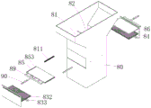
Fig. 5 is an exploded view of a partial structure of the present invention.
Fig. 6 is a schematic view showing the construction of the first filter element and the first baffle of the present invention.
Fig. 7 is a schematic structural view of the scraping member of the present invention.
Fig. 8 is an exploded view of the scraper member of the present invention.
Fig. 9 is an exploded view of the scraping member of the present invention.
Fig. 10 is a schematic structural view of the slide rail and the slide bar of the present invention.
Fig. 11 is a schematic structural view of a first baffle of the present invention.
Detailed Description
In order to make the technical solutions of the present invention better understood, the technical solutions in the embodiments of the present invention will be clearly and completely described below with reference to the drawings in the embodiments of the present invention.
As shown in fig. 1-11, a vertical mill type powder concentrator capable of returning materials, which comprises a support 1, a casing 2, a grinding disc 3, a power device 4, a grinding roller 5, a powder selecting device 6 and a driving device 7, wherein the support 1 is a metal seat, the grinding disc 3 is placed on the support 1, a grinding concave part 30 is arranged on the grinding disc 3, the grinding concave part 30 is a groove adjacent to the periphery of the grinding disc 3, the inner wall of the grinding concave part 30 is an arc-shaped surface, a conical part 31 is arranged in the middle of the grinding disc 3, the inclination angle of the conical part 31 is 120 °, and when stones fall onto the conical part 31, stones fall into the grinding concave part 30 along the conical surface; the power device 4 is used for driving the grinding disc 3 to rotate, the power device 4 is a servo motor on the current market, and an output shaft of the power device 4 is in rotation stopping connection with the grinding disc 3 through a metal shaft, so that the power device 4 drives the grinding disc 3 to rotate clockwise or anticlockwise; the grinding roller 5 is in a metal cake shape, the grinding roller 5 is partially positioned in the grinding concave part 30, and the grinding roller 5 is obliquely arranged; the driving device 7 is a motor, the driving device 7 drives the grinding roller 5 to rotate, so that the grinding roller 5 can grind stone particles, the driving device 7 is a cylinder, and the driving device 7 drives the grinding roller 5 to move left and right, namely, the driving device 7 pushes the roller mill to leave the grinding disc.
Further, the casing 2 is a shell, and the casing 2 is connected with the bracket 1; a feeding pipe 21 is arranged on the machine shell 2, and the feeding pipe 21 is a metal pipe; the lower end opening of the feeding pipe 21 corresponds to the middle part of the grinding disc 3, the upper part of the shell 2 is provided with a discharging pipe 22, the discharging pipe 22 is positioned above the powder selecting device 6, and materials after being selected by the powder selecting device 6 are discharged from the discharging pipe 22; the powder selecting device 6 is a powder selecting device of a roller mill existing in the current market, is the prior art, and the powder selecting device 6 is arranged at the upper part of the shell 2; the casing 2 is also provided with a hot air inlet pipe 23, and hot air is introduced into the hot air inlet pipe 23 from bottom to top, so that fine particles can be blown.
Specifically, a material guiding device 8 is installed in the middle of the casing 3, the material guiding device 8 includes a material guiding pipe 80, a first channel 81, a second channel 82, a first filtering part 83 and a second filtering part 84, wherein the material guiding pipe 80 is a funnel-shaped metal pipe, the first channel 81 is a channel formed on the material guiding pipe 80, the second channel 82 is a channel symmetrical to the first channel 81, the first filtering part 83 is disposed in the first channel 81, the first filtering part 83 filters particles meeting a standard size, the first filtering part 83 includes a filter plate 832, a driving motor 833, a vibration plate 834 and an elastic part 835, the filter plate 832 is a metal plate, a plurality of filtering holes 831 are formed in the filter plate 832, the driving motor 833 is a servo motor, the driving motor 833 is installed on the outer wall of the material guiding pipe 80, and an output shaft of the driving motor 833 is connected to the filter plate 832, the filter plate 832 rotates in the first passage 81, the vibration plate 834 is a metal plate, the vibration plate 834 has a bent portion 839, at least two rotation rollers 836 are provided on the vibration plate 834, the rotation rollers 836 are abrasion-resistant plastic rollers, and a space is provided between the two rotation rollers 836, and the filter plate 832 abuts against the rotation rollers 836 when the filter plate 832 rotates.
Further, the elastic member 835 is a metal spring, one end of the elastic member 835 is connected to the filter plate 832, and the other end of the elastic member 835 is connected to the inner wall of the first channel 81, so that the elastic member 835 is elastically deformed when the filter plate 832 contacts the vibration plate 834.
Specifically, a first baffle 85 is provided in the first passage 81, the first baffle 85 is provided above the first filter member 83, the first baffle 85 is a metal plate, a cavity 850 is formed on the first baffle 85, and a wind hole 851 is formed on the first baffle 85, the wind hole 851 is communicated with the cavity 850, so that the wind in the cavity 850 can be blown out downward from among the wind holes 851, at each of the air holes 851, a diaphragm 852 is provided, the diaphragm 852 being an elastic rubber sheet, the diaphragm 852 blocks the air hole 851, and the diaphragm 852 has a slit, so that the air in the cavity 850 is blown out from the slit, and the first baffle 85 is communicated with an air pipe 89, the air pipe 89 is used for feeding air into the cavity 850, meanwhile, a pushing cylinder 90 is arranged on the upper outer wall of the material guiding pipe 80, and the pushing cylinder 90 can pull the first baffle 85 to act.
Further, a sliding rail 811 is arranged on the inner wall of the first channel 81, the sliding rail 811 is a metal rail, a sliding strip 853 is arranged on the side wall of the first baffle 85, the sliding strip 853 is a metal strip, an insertion groove 859 is arranged on the side wall of the sliding strip 853, the first baffle 85 can be inserted into the insertion groove 859, so that the first baffle 85 is connected with the sliding strip 853, a movable groove 819 is arranged on the sliding rail 811, the sliding strip 853 is partially inserted into the movable groove 819, a rolling member 854 is arranged on the side wall of the sliding strip 853, the rolling member 854 is a metal ball, the rolling member 854 is in contact with the inner wall of the movable groove 819, and the sliding strip 853 can move along the sliding rail 811.
Specifically, a fixing strip 801 is arranged on the side wall of the material guide pipe 80, the fixing strip 801 is a metal strip, a material scraping piece 802 is detachably connected to the fixing strip 801, the material scraping piece 802 is used for scraping the bottom of the first baffle 85, an insertion concave part 804 is arranged on the fixing strip 801, the insertion concave part 804 is of a T-shaped structure, an insertion convex part 803 is arranged on the material scraping piece 802, the insertion convex part 803 is a T-shaped convex part, and the insertion convex part 803 is inserted into the insertion concave part 804; and a clamping convex part 808 is arranged on the inner wall of the inserting concave part 804, the clamping convex part 808 is a convex part integrally formed with the fixing strip 801, a clamping concave part 809 is arranged on the inserting convex part 803, and when the scraping piece 802 is inserted into the fixing strip 801, the clamping convex part 808 is clamped into the clamping concave part 809.
Further, the material scraping member 802 includes a material scraping rod 805 and an elastic scraping blade 806, the insertion convex portion 803 is located on the material scraping rod 805, the material scraping rod 805 is a metal rod, the elastic scraping blade 806 is a hard rubber sheet, the elastic scraping blade 806 is adhered to the material scraping rod 805, the elastic scraping blade 806 is in contact with a supporting portion of the first baffle 85, the elastic scraping blade 806 is provided with an elastic convex portion 807 with an arch structure, and when the elastic scraping blade 806 scrapes dust, the dust passes through the elastic convex portion 807 and falls.
Specifically, the second filter element 84 is disposed in the second channel 82, and the second filter element 84 is symmetrical to the first filter element 83, so that the specific structure thereof is the same as that of the first filter element 83; the detailed description is omitted, the second baffle 86 is located above the second filter element 84, the detailed structure of the second baffle 86 is the same as that of the first baffle 85, and the installation manner of the second baffle 86 is the same as that of the first baffle 85, so the detailed description is omitted here.
It is to be understood that the described embodiments are merely a few embodiments of the invention, and not all embodiments. All other embodiments, which can be derived by a person skilled in the art from the embodiments given herein without making any creative effort, shall fall within the protection scope of the present invention.
Claims (10)
1. A vertical mill type powder concentrator capable of returning materials comprises a support (1), a machine shell (2) arranged on the support (1), a grinding disc (3) arranged at the lower part of the machine shell (2), a power device (4) used for driving the grinding disc (3) to rotate, a grinding roller (5) matched with the grinding disc (3), a powder selecting device (6) and a driving device (7) arranged at the upper part of the machine shell (2), wherein a feeding pipe (21) is arranged on the machine shell (2), an opening at the lower part of the feeding pipe (21) corresponds to the grinding disc (3), a discharging pipe (22) positioned above the powder selecting device (6) is arranged at the upper part of the machine shell (2), and a hot air inlet pipe (23) is arranged at the lower part of the machine shell (2); the method is characterized in that: the material guide device (8) is arranged in the machine shell (2), the material guide device (8) comprises a material guide pipe (80) with a funnel-shaped structure, a first channel (81) formed on the material guide pipe (80), a second channel (82) formed on the material guide pipe (80), a first filtering part (83) arranged in the first channel (81) and a second filtering part (84) arranged in the second channel (82), a first baffle (85) capable of closing the first channel (81) is arranged in the first channel (81), and a second baffle (86) capable of closing the second channel (82) is arranged in the second channel (82).
2. A vertical mill type powder concentrator capable of feeding back according to claim 1, characterized in that: first filtering part (83) including filter plate (832) that have filtration pore (831), be used for the drive filter plate (832) pivoted driving motor (833), locate vibrations board (834) in first passageway (81) and with elastic component (835) that vibrations board (834) are connected, elastic component (835) with first passageway (81) inner wall links to each other, first baffle (85) are located filter plate (832) top.
3. A vertical mill type powder concentrator capable of feeding back according to claim 2, characterized in that: the vibrating plate (834) is provided with at least two rotating rollers (836) which are arranged at equal intervals, and the rotating rollers (836) are abutted to the filter plate (832).
4. A vertical mill type powder concentrator capable of feeding back according to claim 1, characterized in that: a cavity (850) is arranged above the first baffle (85), a plurality of air holes (851) communicated with the cavity (850) are formed in the first baffle (85), and diaphragms (852) are arranged on the air holes (851).
5. A vertical mill type powder concentrator capable of feeding back according to claim 1, characterized in that: be equipped with slide rail (811) on first passageway (81) inner wall, be equipped with on first baffle (85) with slide rail (811) matched with draw runner (853), be equipped with a plurality of rolling piece (854) on draw runner (853).
6. A vertical mill type powder concentrator capable of feeding back according to claim 5, wherein: the material guide pipe (80) is provided with a fixing strip (801), and the fixing strip (801) is detachably connected with a material scraping part (802) which is abutted against the bottom of the first baffle (85).
7. A vertical mill type powder concentrator capable of feeding back according to claim 6, wherein: the material scraping piece (802) is provided with a T-shaped inserting convex part (803), the fixing strip (801) is provided with an inserting concave part (804) for the inserting of the inserting convex part (803), and the inserting concave part (804) is of a T-shaped structure.
8. A vertical mill type powder concentrator capable of feeding back according to claim 7, wherein: the scraping member (802) comprises a scraping rod (805) and an elastic scraping blade (806) bonded with the scraping rod (805), and the elastic scraping blade (806) is in contact with the bottom of the first baffle plate (85).
9. A vertical mill type powder concentrator capable of feeding back according to claim 8, wherein: the elastic scraping blade (806) is provided with an elastic convex part (807) with an arch structure.
10. A vertical mill type powder concentrator capable of feeding back according to claim 8, wherein: the inner wall of the inserting concave part (804) is provided with a clamping convex part (808), and the inserting convex part (803) is provided with a clamping concave part (809) matched with the clamping convex part (808).
Priority Applications (1)
| Application Number | Priority Date | Filing Date | Title |
|---|---|---|---|
| CN202010146022.4A CN111229390B (en) | 2020-03-05 | 2020-03-05 | Vertical mill type powder concentrator capable of returning materials |
Applications Claiming Priority (1)
| Application Number | Priority Date | Filing Date | Title |
|---|---|---|---|
| CN202010146022.4A CN111229390B (en) | 2020-03-05 | 2020-03-05 | Vertical mill type powder concentrator capable of returning materials |
Publications (2)
| Publication Number | Publication Date |
|---|---|
| CN111229390A CN111229390A (en) | 2020-06-05 |
| CN111229390B true CN111229390B (en) | 2021-10-22 |
Family
ID=70871727
Family Applications (1)
| Application Number | Title | Priority Date | Filing Date |
|---|---|---|---|
| CN202010146022.4A Active CN111229390B (en) | 2020-03-05 | 2020-03-05 | Vertical mill type powder concentrator capable of returning materials |
Country Status (1)
| Country | Link |
|---|---|
| CN (1) | CN111229390B (en) |
Citations (12)
| Publication number | Priority date | Publication date | Assignee | Title |
|---|---|---|---|---|
| JPH0311313B2 (en) * | 1983-02-09 | 1991-02-15 | Mitsubishi Chem Ind | |
| EP1816862A1 (en) * | 2006-02-01 | 2007-08-08 | Samsung Electronics Co., Ltd. | Video playback apparatus and method for controlling the same |
| CN101318154A (en) * | 2008-06-20 | 2008-12-10 | 张桂才 | Internal screening roller type vertical mill |
| CN101628392A (en) * | 2009-07-27 | 2010-01-20 | 浙江吉天环保科技有限公司 | Environment-friendly woodwork vertical polishing machine |
| JP4811713B2 (en) * | 2005-12-13 | 2011-11-09 | 宇部興産機械株式会社 | Cement clinker grinding equipment |
| WO2012026422A1 (en) * | 2010-08-27 | 2012-03-01 | 三菱重工業株式会社 | Vertical roller mill |
| CN102795633A (en) * | 2012-08-28 | 2012-11-28 | 北京矿冶研究总院 | Coal-series kaolin gaseous suspension calcining method |
| US8662429B2 (en) * | 2012-01-17 | 2014-03-04 | Fellowes, Inc. | Modular document destruction system |
| CN208245192U (en) * | 2018-02-13 | 2018-12-18 | 石家庄科林威尔环保科技有限公司 | A kind of powder concentrator |
| CN109092447A (en) * | 2018-08-21 | 2018-12-28 | 北京电力设备总厂有限公司 | A kind of anthracite Vertical Mill |
| CN109590074A (en) * | 2019-02-18 | 2019-04-09 | 江苏新业重工股份有限公司 | A kind of vertical mill raw material stoving system |
| CN210022322U (en) * | 2018-12-24 | 2020-02-07 | 常州坚鹏建材有限公司 | Feed back system of mineral powder vertical mill |
Family Cites Families (1)
| Publication number | Priority date | Publication date | Assignee | Title |
|---|---|---|---|---|
| US8070081B2 (en) * | 2009-05-14 | 2011-12-06 | Wark Rickey E | Pressure monitor for pulverizer |
-
2020
- 2020-03-05 CN CN202010146022.4A patent/CN111229390B/en active Active
Patent Citations (12)
| Publication number | Priority date | Publication date | Assignee | Title |
|---|---|---|---|---|
| JPH0311313B2 (en) * | 1983-02-09 | 1991-02-15 | Mitsubishi Chem Ind | |
| JP4811713B2 (en) * | 2005-12-13 | 2011-11-09 | 宇部興産機械株式会社 | Cement clinker grinding equipment |
| EP1816862A1 (en) * | 2006-02-01 | 2007-08-08 | Samsung Electronics Co., Ltd. | Video playback apparatus and method for controlling the same |
| CN101318154A (en) * | 2008-06-20 | 2008-12-10 | 张桂才 | Internal screening roller type vertical mill |
| CN101628392A (en) * | 2009-07-27 | 2010-01-20 | 浙江吉天环保科技有限公司 | Environment-friendly woodwork vertical polishing machine |
| WO2012026422A1 (en) * | 2010-08-27 | 2012-03-01 | 三菱重工業株式会社 | Vertical roller mill |
| US8662429B2 (en) * | 2012-01-17 | 2014-03-04 | Fellowes, Inc. | Modular document destruction system |
| CN102795633A (en) * | 2012-08-28 | 2012-11-28 | 北京矿冶研究总院 | Coal-series kaolin gaseous suspension calcining method |
| CN208245192U (en) * | 2018-02-13 | 2018-12-18 | 石家庄科林威尔环保科技有限公司 | A kind of powder concentrator |
| CN109092447A (en) * | 2018-08-21 | 2018-12-28 | 北京电力设备总厂有限公司 | A kind of anthracite Vertical Mill |
| CN210022322U (en) * | 2018-12-24 | 2020-02-07 | 常州坚鹏建材有限公司 | Feed back system of mineral powder vertical mill |
| CN109590074A (en) * | 2019-02-18 | 2019-04-09 | 江苏新业重工股份有限公司 | A kind of vertical mill raw material stoving system |
Also Published As
| Publication number | Publication date |
|---|---|
| CN111229390A (en) | 2020-06-05 |
Similar Documents
| Publication | Publication Date | Title |
|---|---|---|
| CN201175700Y (en) | Projectile particle material sorting device | |
| CN111203304A (en) | A mill for preparing calcium carbonate powder | |
| CN114558677A (en) | Energy-saving ore mining crushing machine with dust removal function | |
| CN117000428A (en) | A kind of iron ore sorting and processing equipment for mining areas | |
| CN111229390B (en) | Vertical mill type powder concentrator capable of returning materials | |
| CA2045659C (en) | Air concentrator | |
| CN212167629U (en) | Material guide device for vertical roller mill | |
| CN212143468U (en) | Light and heavy garbage material separator | |
| CN212143467U (en) | Light and heavy garbage material conveying, separating and dedusting system | |
| CN209077188U (en) | A kind of aggregate regeneration separator | |
| CN112337623A (en) | Grinding device is used in production of lithium cell graphite negative electrode material | |
| CN117123319A (en) | Stone crushing equipment | |
| CN210386186U (en) | A magnetic separator | |
| CN218049011U (en) | Negative pressure winnowing adjustment self-adaptive system | |
| CN109092486A (en) | A kind of lacquer coating fining milling apparatus | |
| CN201848280U (en) | Discharge and screening device of ball mill | |
| CN213590621U (en) | a crushing mill | |
| CN210635434U (en) | Automatic charging device for Czochralski monocrystalline silicon re-feeding barrel | |
| CN217250700U (en) | Centrifugal efficient powder concentrator | |
| CN209901718U (en) | Anti-blocking specific gravity stoner | |
| CN221268332U (en) | Ring hammer crusher | |
| KR20060019408A (en) | Aggregate and soil production equipment using construction waste | |
| CN112474353A (en) | Melon seed winnowing device | |
| CN206587917U (en) | Centrifuge the dry method cull eliminator that drifts along | |
| CN218049051U (en) | Particle classifier with screening function |
Legal Events
| Date | Code | Title | Description |
|---|---|---|---|
| PB01 | Publication | ||
| PB01 | Publication | ||
| SE01 | Entry into force of request for substantive examination | ||
| SE01 | Entry into force of request for substantive examination | ||
| GR01 | Patent grant | ||
| GR01 | Patent grant |