CN111227908B - Thrombus taking device - Google Patents
Thrombus taking device Download PDFInfo
- Publication number
- CN111227908B CN111227908B CN202010076114.XA CN202010076114A CN111227908B CN 111227908 B CN111227908 B CN 111227908B CN 202010076114 A CN202010076114 A CN 202010076114A CN 111227908 B CN111227908 B CN 111227908B
- Authority
- CN
- China
- Prior art keywords
- thrombus
- cutting
- tube
- weaving
- inner catheter
- Prior art date
- Legal status (The legal status is an assumption and is not a legal conclusion. Google has not performed a legal analysis and makes no representation as to the accuracy of the status listed.)
- Active
Links
- 208000007536 Thrombosis Diseases 0.000 title claims abstract description 194
- 238000013151 thrombectomy Methods 0.000 claims abstract description 14
- 238000009941 weaving Methods 0.000 claims description 23
- 230000001681 protective effect Effects 0.000 claims description 9
- 238000005452 bending Methods 0.000 claims description 6
- 238000013156 embolectomy Methods 0.000 claims 1
- 230000008878 coupling Effects 0.000 abstract description 6
- 238000010168 coupling process Methods 0.000 abstract description 6
- 238000005859 coupling reaction Methods 0.000 abstract description 6
- 239000007787 solid Substances 0.000 abstract description 3
- 230000000694 effects Effects 0.000 description 11
- 210000004204 blood vessel Anatomy 0.000 description 10
- 238000000034 method Methods 0.000 description 6
- 230000008569 process Effects 0.000 description 6
- 230000008602 contraction Effects 0.000 description 3
- 238000010586 diagram Methods 0.000 description 3
- 238000009940 knitting Methods 0.000 description 3
- 230000009471 action Effects 0.000 description 2
- 230000001154 acute effect Effects 0.000 description 2
- 210000001367 artery Anatomy 0.000 description 2
- 230000017531 blood circulation Effects 0.000 description 2
- 208000005189 Embolism Diseases 0.000 description 1
- 230000015572 biosynthetic process Effects 0.000 description 1
- 239000008280 blood Substances 0.000 description 1
- 210000004369 blood Anatomy 0.000 description 1
- 230000002490 cerebral effect Effects 0.000 description 1
- 238000010276 construction Methods 0.000 description 1
- 230000007547 defect Effects 0.000 description 1
- 238000002651 drug therapy Methods 0.000 description 1
- 238000000605 extraction Methods 0.000 description 1
- 239000012634 fragment Substances 0.000 description 1
- 230000036541 health Effects 0.000 description 1
- 238000011084 recovery Methods 0.000 description 1
- 230000002441 reversible effect Effects 0.000 description 1
- 210000003462 vein Anatomy 0.000 description 1
Images


Classifications
-
- A—HUMAN NECESSITIES
- A61—MEDICAL OR VETERINARY SCIENCE; HYGIENE
- A61B—DIAGNOSIS; SURGERY; IDENTIFICATION
- A61B17/00—Surgical instruments, devices or methods
- A61B17/22—Implements for squeezing-off ulcers or the like on inner organs of the body; Implements for scraping-out cavities of body organs, e.g. bones; for invasive removal or destruction of calculus using mechanical vibrations; for removing obstructions in blood vessels, not otherwise provided for
- A61B17/221—Gripping devices in the form of loops or baskets for gripping calculi or similar types of obstructions
-
- A—HUMAN NECESSITIES
- A61—MEDICAL OR VETERINARY SCIENCE; HYGIENE
- A61B—DIAGNOSIS; SURGERY; IDENTIFICATION
- A61B17/00—Surgical instruments, devices or methods
- A61B17/22—Implements for squeezing-off ulcers or the like on inner organs of the body; Implements for scraping-out cavities of body organs, e.g. bones; for invasive removal or destruction of calculus using mechanical vibrations; for removing obstructions in blood vessels, not otherwise provided for
- A61B2017/22038—Implements for squeezing-off ulcers or the like on inner organs of the body; Implements for scraping-out cavities of body organs, e.g. bones; for invasive removal or destruction of calculus using mechanical vibrations; for removing obstructions in blood vessels, not otherwise provided for with a guide wire
-
- A—HUMAN NECESSITIES
- A61—MEDICAL OR VETERINARY SCIENCE; HYGIENE
- A61B—DIAGNOSIS; SURGERY; IDENTIFICATION
- A61B17/00—Surgical instruments, devices or methods
- A61B17/22—Implements for squeezing-off ulcers or the like on inner organs of the body; Implements for scraping-out cavities of body organs, e.g. bones; for invasive removal or destruction of calculus using mechanical vibrations; for removing obstructions in blood vessels, not otherwise provided for
- A61B2017/22079—Implements for squeezing-off ulcers or the like on inner organs of the body; Implements for scraping-out cavities of body organs, e.g. bones; for invasive removal or destruction of calculus using mechanical vibrations; for removing obstructions in blood vessels, not otherwise provided for with suction of debris
-
- A—HUMAN NECESSITIES
- A61—MEDICAL OR VETERINARY SCIENCE; HYGIENE
- A61B—DIAGNOSIS; SURGERY; IDENTIFICATION
- A61B17/00—Surgical instruments, devices or methods
- A61B17/22—Implements for squeezing-off ulcers or the like on inner organs of the body; Implements for scraping-out cavities of body organs, e.g. bones; for invasive removal or destruction of calculus using mechanical vibrations; for removing obstructions in blood vessels, not otherwise provided for
- A61B2017/22094—Implements for squeezing-off ulcers or the like on inner organs of the body; Implements for scraping-out cavities of body organs, e.g. bones; for invasive removal or destruction of calculus using mechanical vibrations; for removing obstructions in blood vessels, not otherwise provided for for crossing total occlusions, i.e. piercing
-
- A—HUMAN NECESSITIES
- A61—MEDICAL OR VETERINARY SCIENCE; HYGIENE
- A61B—DIAGNOSIS; SURGERY; IDENTIFICATION
- A61B17/00—Surgical instruments, devices or methods
- A61B17/22—Implements for squeezing-off ulcers or the like on inner organs of the body; Implements for scraping-out cavities of body organs, e.g. bones; for invasive removal or destruction of calculus using mechanical vibrations; for removing obstructions in blood vessels, not otherwise provided for
- A61B17/221—Gripping devices in the form of loops or baskets for gripping calculi or similar types of obstructions
- A61B2017/2212—Gripping devices in the form of loops or baskets for gripping calculi or similar types of obstructions having a closed distal end, e.g. a loop
Landscapes
- Health & Medical Sciences (AREA)
- Surgery (AREA)
- Life Sciences & Earth Sciences (AREA)
- Heart & Thoracic Surgery (AREA)
- Nuclear Medicine, Radiotherapy & Molecular Imaging (AREA)
- Vascular Medicine (AREA)
- Engineering & Computer Science (AREA)
- Biomedical Technology (AREA)
- Orthopedic Medicine & Surgery (AREA)
- Medical Informatics (AREA)
- Molecular Biology (AREA)
- Animal Behavior & Ethology (AREA)
- General Health & Medical Sciences (AREA)
- Public Health (AREA)
- Veterinary Medicine (AREA)
- Surgical Instruments (AREA)
Abstract
The invention discloses a thrombus thrombectomy device. Including operating handle (1), the key is the one end of operating handle (1) rigid coupling outer pipe (2), cup joints a thrombus sheath pipe (3) on outer pipe (2), and the front end rigid coupling thrombus cracker (4) of outer pipe (2), is equipped with one in outer pipe (2) interior pipe (5), is equipped with slidable thrombus collector (6) and spacing solid fixed ring (18) on interior pipe (5), is equipped with cutting button (7) that control thrombus cracker (4) receive and release on operating handle (1). The invention has reliable and convenient operation, and is an excellent safe and reliable replacement design of the thrombus removal instrument.
Description
The technical field is as follows:
the invention relates to a medical appliance, in particular to a thrombus remover which can take out thrombus in a human blood vessel.
Background art:
often thrombosis in the internal blood vessel of human body has great influence to human health, can threaten life even, because of the thrombus that various reasons can form in artery or venous system in the human body, when current drug therapy can't control or eliminate the thrombus, need utilize the apparatus to carry out breakage and take out to the thrombus. At present, a hollow catheter is used for extending into a blood vessel thrombosis position, then a suction device is used for sucking the thrombus into the catheter and outputting the thrombus out of a human body, however, when the thrombus is formed for a long time, the hardness of the thrombus is greatly improved, the thrombus is difficult to be sucked into the catheter by the thrombus suction catheter, another bowl-shaped thrombus taking guide wire is needed to cut or break the thrombus, then a collecting net is used for collecting the thrombus block, and then the human body is taken out through the catheter, but for harder thrombus, the effect of cutting thrombus by the bowl-shaped thrombus taking guide wire is not good, the collection efficiency of the existing collection net to the broken thrombus blocks is poor, the thrombus blocks often escape from the collection net and enter the blood flow of the blood vessel, the entry of thrombus fragments as described above into smaller or delicate blood vessels can form new thrombus obstructions, particularly into sensitive sites such as cerebral vessels, and can even lead to serious embolisms. Therefore, how to improve the cutting and collecting efficiency of the thrombus and avoid new blockage caused by broken thrombus is still a problem to be solved for taking out the thrombus from the human body.
The purpose of the invention is as follows:
the invention aims to disclose a thrombus thrombectomy device with high safety and excellent effect.
The technical solution for realizing the invention is as follows: including operating handle, the key is the one end of operating handle rigid coupling outer pipe, cup joints a thrombus sheath pipe on the outer pipe, and the front end rigid coupling thrombus cracker of outer pipe is equipped with an inner catheter in the outer pipe, is equipped with slidable thrombus collector and spacing solid fixed ring on the inner catheter, is equipped with the cutting button that control thrombus cracker receive and releases on the operating handle.
The thrombus crusher is provided with at least two cutting wires which respectively form a bending closed structure for cutting thrombus, the free end of each cutting wire penetrates through the elastic protection tube and extends to be connected with the push-pull tube in the outer catheter, one end of the protection tube is fixedly connected with the inner catheter positioned at the central position of the protection tube, and the push-pull tube is sleeved on the inner catheter.
The bending closed structure comprises two protection tubes and a cutting wire between free ends of the two protection tubes.
The cutting button is fixedly connected with one end of a push-pull pipe sleeved on the inner guide pipe, and the cutting button drives the push-pull pipe to move relative to the inner guide pipe.
The thrombus collector's front end and the front end fixed connection that collects of collecting the net, collect the wavy edge of opening of net and be connected with the back end through the stay cord, front end and back front end all have the through-hole.
The edge of the wavy open port of the collecting net is formed by at least three weaving convex parts and three weaving concave parts which are mutually alternated, one end of the pull rope is connected with the top point of the weaving convex part, and the other end of the pull rope is connected with the rear front end; or one end of the pull rope is connected with the rear front end, and the other end of the pull rope passes through the vertex of one weaving convex part, then passes through the meshes at the edge of the weaving concave part, and finally passes through the vertex of the other adjacent weaving convex part to be connected with the rear front end.
Two cutting wires in the two bending closed structures of the thrombus crusher are arranged in parallel.
The thrombus crusher is provided with three cutting wires, each cutting wire forms a bent closed structure, and two adjacent cutting wires penetrate through the same protection pipe.
A guide wire is arranged in the inner catheter.
The invention discloses a thrombus taking device with high safety and excellent effect, wherein the thrombus breaking device has unique structural design and excellent thrombus breaking effect, and a thrombus collector has good collection effect on broken thrombus blocks, so that the thrombus blocks are prevented from escaping from the thrombus collector and entering the blood stream of a human body to form new thrombus and blockage.
Description of the drawings:
fig. 1 is a schematic overall structure diagram of an embodiment of the present invention.
Fig. 2 is an enlarged schematic view of the thrombus collector in fig. 1.
FIG. 3 is a schematic view showing the construction of the thrombus collector.
FIG. 4 is a schematic cross-sectional view of the thrombectomy device of FIG. 1.
Fig. 5 is a schematic view of a cross-sectional structure a-a in fig. 1.
FIG. 6 is a schematic structural view of another embodiment of a thrombus breaker.
Fig. 7 is a partial sectional structural view of the operating handle.
Fig. 8 is an enlarged view of the section in fig. 7.
FIG. 9 is a schematic view showing a contracted state of the thrombus crusher.
FIG. 10 is a view showing the positional relationship between a thrombus collector and a thrombus crusher used for arterial thrombectomy.
FIG. 11 is a view showing a positional relationship between a thrombus collector and a thrombus crusher used for venous thrombectomy.
FIG. 12 is a view showing a positional relationship between a thrombus collector and a thrombus crusher used in an arterial/venous thrombectomy.
Fig. 13 is a schematic diagram of the process of removing thrombus.
The specific implementation mode is as follows:
the detailed description of the embodiments of the present invention is given in conjunction with the accompanying drawings of the specification, and it should be noted that the detailed description of the embodiments is provided for the purpose of comprehensive understanding of the technical solution of the present invention, and should not be construed as limiting the scope of the claims of the present invention.
Referring to fig. 1 to 13, a technical solution of an embodiment of the present invention is: including operating handle 1, the key is the one end of operating handle 1 rigid coupling outer catheter 2, cup joints a thrombus sheath pipe 3 on the outer catheter 2, and outer catheter 2's front end rigid coupling thrombus cracker 4 is equipped with an inner catheter 5 in the outer catheter 2, is equipped with slidable thrombus collector 6 and spacing solid fixed ring 18 on the inner catheter 5, is equipped with the cutting button 7 that control thrombus cracker 4 receive and releases on the operating handle 1. When the thrombus crusher is in practical use, the thrombus crusher 4 and the thrombus collector 6 are in a contraction state and are both positioned in the thrombus-absorbing sheath 3, the thrombus-absorbing sheath 3 is stretched into a human blood vessel, when a thrombus is encountered, the front end of the inner catheter 5 exposed out of the thrombus-absorbing sheath 3 firstly passes through the thrombus, then the thrombus-absorbing sheath 3 also passes through the thrombus and is retracted into the thrombus-absorbing sheath 3, the thrombus collector 6 is positioned in front of the thrombus and is unfolded, the thrombus crusher 4 is positioned behind the thrombus or in the middle of the thrombus, the cutting button 7 is pushed and pulled in a reciprocating manner to repeatedly contract, release and unfold the thrombus crusher 4, the contraction, release and expansion process is the process of breaking thrombus, the broken thrombus block enters the thrombus collector 6, finally the thrombus-aspiration sheath tube 3 is pushed forwards, so that the thrombus breaker 4 and the thrombus collector 6 are contracted and enter the thrombus-aspiration sheath tube 3, and the thrombus-aspiration sheath tube 3 is taken out to complete the operation of breaking thrombus and taking out thrombus from the human blood vessel.
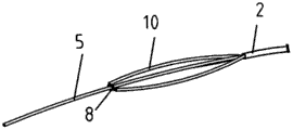
The thrombus crusher 4 is provided with at least two cutting wires 8 which respectively form a bent closed structure for cutting thrombus, the free end 9 of each cutting wire 8 passes through an elastic protection tube 10 and extends to be connected with a push-pull tube 11 in the outer catheter 2, one end of the protection tube 10 is fixedly connected with the inner catheter 5 positioned at the central position of the protection tube 10, and the push-pull tube 11 is sleeved on the inner catheter 5 (shown in figure 4); when the thrombus crusher 4 is used, the push-pull action of the push-pull tube 11 along the inner catheter 5 drives the free end 9 of the cutting wire 8 to move back and forth, so that the bent closed structure is contracted or released to be expanded, the cutting wire 8 is extruded into thrombus when being expanded, and the thrombus is cut when being contracted.
The bending closed structure formed by the cutting wire of the thrombus crusher 4 comprises two protective tubes 10 and the cutting wire 8 between the free ends of the two protective tubes 10; the other end of the protective tube 10 is fixedly connected to the inner catheter 5 as described above, so that when the cutting wire 8 is contracted, the entire protective tube 10 is finally gathered or attached to the inner catheter 5 (shown in fig. 9) by the pulling of the cutting wire 8 to be easily retracted into the tampon sheath 3.
The cutting button 7 is fixedly connected to one end of a push-pull tube 11 sleeved on the inner guide tube 5, the cutting button 7 is sleeved on the inner guide tube 5, the cutting button 7 has a convex portion exposed out of the operating handle 1, the push-pull tube 11 is driven to move relative to the inner guide tube 5 by pushing and pulling the convex portion, and finally the free end 9 of the cutting wire 8 is driven to move to contract or release the curved closed structure (shown in fig. 7-8).
The structure of the thrombus crusher 4 and the function and effect of cutting thrombus have been described above, the cut or broken thrombus block enters the thrombus collector 6 in front of the thrombus crusher 4, the thrombus collector is also arranged in the thrombus crusher of the prior art, the whole structure of the thrombus collector is similar to an umbrella-shaped woven mesh, the thrombus block collected in the umbrella-shaped woven mesh is easily contracted and extruded in the umbrella-shaped woven mesh collecting process, and escapes from the gap between the umbrella-shaped woven mesh and the blood vessel wall, and enters the blood flow again to cause new blockage and thrombus formation in the blood vessel system, thus causing more dangerous illness, for example, the small thrombus block enters the human cerebrovascular system. In order to overcome the possible defects of the prior art, the front end head 12 of the thrombus collector 6 is fixedly connected with the collection front end of the collection net 13, the edge of the wavy open port of the collection net 13 is connected with the rear end head 15 through a pull rope 14, and the front end head and the rear end head (12 and 15) are provided with through holes; the inner catheter 5 passes through the through holes of the front and rear ends (12, 15), the thrombus collector 6 can slide and move on the inner catheter 5, the inner catheter 5 is provided with a limit fixing ring 18, the front and rear ends (12, 15) of the thrombus collector 6 are positioned at two sides of the limit fixing ring 18, if the thrombus-aspiration sheath 3 retracts, namely moves rightwards in the structure shown in fig. 1, the thrombus collector 6 is separated from the thrombus-aspiration sheath 3 and is unfolded as shown in fig. 1 and 2, the limit fixing ring 18 limits the slidable movement of the thrombus collector 6, when the thrombus collector 6 needs to be recovered, the thrombus-aspiration sheath 3 is pushed forwards, the port of the thrombus-aspiration sheath 3 presses on the pull rope 14 of the thrombus collector 6 and enables the thrombus collector 6 to move leftwards, when the rear end 15 touches the limit fixing ring 18, the thrombus collector 6 stops moving leftwards, the port of the thrombus collector 3 continues to press on the pull rope 14 of the thrombus collector 6, the pulling rope 14 is forced to move towards the axle center and the wave-shaped edge of the collecting net 13 is pulled to move towards the axle center, because of the wavy edge, the crest part thereof moves towards the axis first, which substantially plays a role of closing the opening of the collection net 13 first, preventing thrombus blocks in the collection net 13 from escaping from the collection net 13, and moving leftwards along with the continuation of the thrombus-aspiration sheath tube 3, under the action of the draw cord 14, the crest portion of the edge of the collecting wire 13 substantially closes the opening of the collecting wire 13, meanwhile, the collecting net 13 is gradually contracted in the radial direction, and finally, the collecting net 13 is totally recycled into the sheath tube 3 of the suction plug, the unique design of the thrombus collector 6 realizes the technical effects that the collection net 13 is closed to be open and then gradually and radially contracts when the thrombus blocks are recovered, so that the possibility that the thrombus blocks can escape from the thrombus collector is avoided, and the safety of thrombus extraction operation is greatly improved.
In order to more clearly understand the thrombus collector 6, the wavy open mouth edge of the collecting net 13 of the thrombus collector 6 is formed by at least three weaving convex parts 16 and three weaving concave parts 17 which are mutually alternated, one end of the pull rope 14 is connected with the peak of the weaving convex part 16, and the other end is connected with the rear front end head 15; when the draw cord 14 is pressed by the port of the sheath tube 3, the apex of the knitting projection 16 is deformed by the tensile force of the draw cord 14, and this deformation causes the knitting projection 16 to bend in the axial direction and to be deformed to be slightly longer, so that the knitting projection 16 functions to close the opening of the collecting net 13. Or one end of the pull rope 14 is connected with the rear front end head 15, and the other end of the pull rope passes through the top point of one weaving convex part 16, then passes through the meshes at the edge of the weaving concave part 17, and finally passes through the top point of another adjacent weaving convex part 16 to be connected with the rear front end head 15; when the pulling rope 14 is pressed by the port of the suction plug sheath 3, the weaving convex part 16 bends and deforms in the axial direction, the edge of the weaving concave part 17 is also stressed to bend in the axial direction, and the width of the weaving concave part 17 is also narrowed, namely, two adjacent weaving convex parts 16 have deformation of relatively closing, so that the speed of closing the opening of the collecting net 13 by the weaving convex parts 16 can be further improved, and the thrombus blocks are more effectively prevented from escaping from the collecting net 13.
The state that the cutting wire 8 of the thrombus crusher 4 crushes the thrombus has been described previously, during practical use, two cutting wires 8 in two curved closed structures of the thrombus crusher 4 are arranged in parallel, that is, two planes formed by the two curved closed structures are parallel planes or two planes with an acute angle, when the curved closed structure is unfolded, the cutting wire 8 is extruded into the cutting plane of the thrombus and is basically parallel or is formed with a cutting plane with an acute angle, when the curved closed structure is contracted or an operator rotates the operating handle 1, the cutting wire 8 cuts the thrombus, in practice, when the cutting wire 8 is contracted, the cutting wire 8 also moves towards the inner catheter 5, and a radial cutting effect is generated.
In order to further improve the cutting and crushing effect of the thrombus crusher 4 on thrombus, the thrombus crusher 4 is provided with three cutting wires 8, each cutting wire 8 forms a bent closed structure, and two adjacent cutting wires 8 penetrate through the same protective tube 10 (shown in fig. 6); the three curved closed structures form an integrated structure in the part of the protective tube 10, which increases the rigidity of the thrombus crusher 4 and improves the thrombus cutting effect during cutting, and each curved closed structure is in a fan shape, the three cutting wires 8 obliquely cut into the thrombus during the expansion process and also have radial cutting during contraction, which actually plays a role in grasping the thrombus, which is more obvious when the thrombus crusher 4 starts to crush from the surface of the thrombus, and the effect of crushing the thrombus is further improved.
When the thrombus taking device enters a human blood vessel, the inner catheter 5 firstly contacts the thrombus and penetrates the thrombus, if the hardness of the thrombus is higher, a thin guide wire capable of passing through an inner hole of the inner catheter 5 is arranged in the inner catheter 5, when the inner catheter 5 meets the thrombus, the guide wire is repeatedly pushed, the guide wire firstly penetrates the thrombus, then the inner catheter 5 is pushed to easily penetrate the thrombus, and finally the thrombus suction sheath tube 3 is pushed to penetrate the thrombus.
Referring to FIGS. 10 to 12, FIG. 10 shows the position relationship between the thrombus collector 6 and the thrombus crusher 4 for use in the arterial system thrombectomy device; FIG. 11 shows the positional relationship of the thrombus collector 6 and the thrombus crusher 4 used in the thrombus remover for the venous system; FIG. 12 shows the positional relationship between the thrombus collector 6 and the thrombus crusher 4 in the thrombectomy device for the artery/vein system, that is, one thrombus collector 6 is provided in front of and behind the thrombus crusher 4.
It should be noted that throughout the specification and claims, the front means the position of entering the thrombus further or the left side of the drawing, and the reverse means the rear.
Referring again to FIG. 13, a-f in FIG. 13 are schematic diagrams of the thrombus removal process of the thrombus removal device. FIG. 13-a shows a state where the thrombus sheath 3 (with the thrombus crusher 4 and the thrombus collector 6 in a contracted state inside) passes through the thrombus; FIG. 13-b shows the state where the thrombus collector 6 is released by withdrawing the thrombus sheath 3; FIG. 13-c shows a state where the thrombus crusher 4 in the expanded state is released again after the sheath 3 is retracted again; FIG. 13-d shows a state where the thrombus crusher 4 is retracted into the thrombus-aspiration sheath 3 after the thrombus is crushed; FIG. 13-e shows a state where the recovery of the thrombus collector 6 is started; fig. 13-f shows a state where a part of the collecting net 13 is recovered into the thrombus sheath 3.
Claims (6)
1. A thrombus embolectomy device comprises an operating handle (1), and is characterized in that the operating handle (1) is fixedly connected with one end of an outer catheter (2), the outer catheter (2) is sleeved with a thrombus-absorbing sheath tube (3), the front end of the outer catheter (2) is fixedly connected with a thrombus crusher (4), an inner catheter (5) is arranged in the outer catheter (2), the inner catheter (5) is provided with a slidable thrombus collector (6) and a limiting fixing ring (18), and the operating handle (1) is provided with a cutting button (7) for controlling the thrombus crusher (4) to retract and release; the front end (12) of the thrombus collector (6) is fixedly connected with the collecting front end of the collecting net (13), the edge of a wavy opening of the collecting net (13) is connected with the rear end (15) through a pull rope (14), and the front end (12) and the rear end (15) are provided with through holes; the thrombus crusher (4) is provided with at least two cutting wires (8) which respectively form a bending closed structure for cutting thrombus, the free end (9) of each cutting wire (8) passes through an elastic protection tube (10) and extends to be connected with a push-pull tube (11) in an outer catheter (2), one end of the protection tube (10) is fixedly connected with an inner catheter (5) positioned at the center of the protection tube (10), and the push-pull tube (11) is sleeved on the inner catheter (5); two cutting wires (8) in the two bending closed structures of the thrombus crusher (4) are arranged in parallel.
2. The thrombectomy device according to claim 1, wherein the curved closure structure comprises two protective tubes (10) and a cutting wire (8) between free ends of the two protective tubes (10).
3. The thrombus thrombectomy device according to claim 1 or 2, wherein the cutting button (7) is fixedly connected to one end of a push-pull tube (11) sleeved on the inner catheter (5), and the cutting button (7) drives the push-pull tube (11) to move relative to the inner catheter (5).
4. A thrombectomy device according to claim 3, wherein the edge of the wavy open mouth of the collecting net (13) is formed by at least three weaving protrusions (16) and three weaving recessions (17) alternately, one end of the pulling rope (14) is connected with the top of the weaving protrusion (16), and the other end is connected with the rear end (15); or one end of the pull rope (14) is connected with the rear end head (15), and the other end of the pull rope passes through the top point of one weaving convex part (16), then passes through the grids at the edge of the weaving concave part (17), and finally is connected with the rear end head (15) through the top point of another adjacent weaving convex part (16).
5. The thrombectomy device according to claim 4, wherein the thrombectomy device (4) has two cutting wires (8), each cutting wire (8) forming a curved closed structure, and two adjacent cutting wires (8) passing through the same protective tube (10).
6. The thrombectomy device according to claim 1, wherein a guide wire is disposed in the inner catheter (5).
Priority Applications (1)
| Application Number | Priority Date | Filing Date | Title |
|---|---|---|---|
| CN202010076114.XA CN111227908B (en) | 2020-01-22 | 2020-01-22 | Thrombus taking device |
Applications Claiming Priority (1)
| Application Number | Priority Date | Filing Date | Title |
|---|---|---|---|
| CN202010076114.XA CN111227908B (en) | 2020-01-22 | 2020-01-22 | Thrombus taking device |
Publications (2)
| Publication Number | Publication Date |
|---|---|
| CN111227908A CN111227908A (en) | 2020-06-05 |
| CN111227908B true CN111227908B (en) | 2022-03-22 |
Family
ID=70879797
Family Applications (1)
| Application Number | Title | Priority Date | Filing Date |
|---|---|---|---|
| CN202010076114.XA Active CN111227908B (en) | 2020-01-22 | 2020-01-22 | Thrombus taking device |
Country Status (1)
| Country | Link |
|---|---|
| CN (1) | CN111227908B (en) |
Families Citing this family (6)
| Publication number | Priority date | Publication date | Assignee | Title |
|---|---|---|---|---|
| CN111658076B (en) * | 2020-07-07 | 2024-12-03 | 无锡东峰怡和科技发展有限公司 | A multifunctional venous thrombus removal device |
| CN114642475A (en) * | 2020-12-18 | 2022-06-21 | 上海蓝脉医疗科技有限公司 | Thrombus removing device |
| CN113476135A (en) * | 2021-08-25 | 2021-10-08 | 中国人民解放军陆军第九五八医院 | A device for resection of intestinal anastomotic stricture under endoscope |
| CN114081578B (en) * | 2021-11-23 | 2023-07-14 | 江苏省人民医院(南京医科大学第一附属医院) | A tissue pulverization processing equipment for prostate surgery |
| CN114224431A (en) * | 2021-11-25 | 2022-03-25 | 北京弘海微创科技有限公司 | A safety thrombectomy device |
| CN114886505B (en) | 2022-07-13 | 2022-09-30 | 苏州中天医疗器械科技有限公司 | Step-by-step cutting bolt taking device and bolt taking system |
Citations (7)
| Publication number | Priority date | Publication date | Assignee | Title |
|---|---|---|---|---|
| JPH04240444A (en) * | 1991-01-22 | 1992-08-27 | Asahi Optical Co Ltd | Grip device for endoscope |
| CN1515326A (en) * | 2003-01-07 | 2004-07-28 | 星 周 | Recoverable blood vessel filter |
| CN202490000U (en) * | 2012-02-14 | 2012-10-17 | 周斌 | Medical cerebral thrombosis treating device |
| CN105873528A (en) * | 2014-01-03 | 2016-08-17 | 波士顿科学医学有限公司 | retrieve device |
| CN107374700A (en) * | 2017-08-28 | 2017-11-24 | 北京赛铂医药科技有限公司 | A kind of segmented thrombus is broken to take device |
| CN109998636A (en) * | 2019-05-19 | 2019-07-12 | 常州市三润医疗器械科技有限公司 | A kind of thrombus removes the thrombus remove device of system |
| CN209932890U (en) * | 2018-12-26 | 2020-01-14 | 杭州唯强医疗科技有限公司 | Thrombus capture system |
Family Cites Families (5)
| Publication number | Priority date | Publication date | Assignee | Title |
|---|---|---|---|---|
| CN102499734B (en) * | 2011-11-17 | 2013-06-19 | 祖茂衡 | Remover for thrombus in stents |
| US9168099B2 (en) * | 2012-10-25 | 2015-10-27 | Gyrus Acmi, Inc. | Lithotripsy apparatus using a flexible endoscope |
| US10111677B2 (en) * | 2014-12-11 | 2018-10-30 | Boston Scientific Scimed, Inc. | Retrieval devices and related methods of use |
| US10342571B2 (en) * | 2015-10-23 | 2019-07-09 | Inari Medical, Inc. | Intravascular treatment of vascular occlusion and associated devices, systems, and methods |
| US10258357B1 (en) * | 2017-10-16 | 2019-04-16 | Michael Bruce Horowitz | Catheter based retrieval device with proximal body having axial freedom of movement |
-
2020
- 2020-01-22 CN CN202010076114.XA patent/CN111227908B/en active Active
Patent Citations (7)
| Publication number | Priority date | Publication date | Assignee | Title |
|---|---|---|---|---|
| JPH04240444A (en) * | 1991-01-22 | 1992-08-27 | Asahi Optical Co Ltd | Grip device for endoscope |
| CN1515326A (en) * | 2003-01-07 | 2004-07-28 | 星 周 | Recoverable blood vessel filter |
| CN202490000U (en) * | 2012-02-14 | 2012-10-17 | 周斌 | Medical cerebral thrombosis treating device |
| CN105873528A (en) * | 2014-01-03 | 2016-08-17 | 波士顿科学医学有限公司 | retrieve device |
| CN107374700A (en) * | 2017-08-28 | 2017-11-24 | 北京赛铂医药科技有限公司 | A kind of segmented thrombus is broken to take device |
| CN209932890U (en) * | 2018-12-26 | 2020-01-14 | 杭州唯强医疗科技有限公司 | Thrombus capture system |
| CN109998636A (en) * | 2019-05-19 | 2019-07-12 | 常州市三润医疗器械科技有限公司 | A kind of thrombus removes the thrombus remove device of system |
Also Published As
| Publication number | Publication date |
|---|---|
| CN111227908A (en) | 2020-06-05 |
Similar Documents
| Publication | Publication Date | Title |
|---|---|---|
| CN111227908B (en) | Thrombus taking device | |
| CN212574929U (en) | High-efficient thrombus thrombectomy ware | |
| CN110141303B (en) | Apparatus for breaking thrombus and sucking thrombus | |
| CN113729853B (en) | Bolt breaking support, bolt breaking device and bolt taking system | |
| CN107348990B (en) | Ultrasonic bolt removing system | |
| JP2010520789A (en) | 2-stage snare basket medical device | |
| CN102743207A (en) | Thrombus breaking and thrombus taking device | |
| CN107397575B (en) | Sheaths for thrombus disruption systems | |
| JP2002113010A (en) | Endoscope basket type retrieval tool | |
| CN111134785B (en) | Thrombus taking device | |
| JP2025505167A (en) | Thrombectomy systems and related methods | |
| CN113599034A (en) | Thrombectomy support and thrombectomy system | |
| CN115153750A (en) | A mechanical thrombectomy device and method of use | |
| CN114376669B (en) | Broken bolt support and bolt taking system | |
| CN114224431A (en) | A safety thrombectomy device | |
| CN212547086U (en) | High-efficient thrombus breaker | |
| CN221490149U (en) | A foreign body removal bag under gastroscope | |
| CN113384320A (en) | Urinary calculus stone breaking device for urology surgery | |
| CN213665567U (en) | Stone-fetching gravel basket | |
| CN223554923U (en) | Diameter-variable thrombus stripping device | |
| CN115444508B (en) | Thrombectomy device and thrombectomy system | |
| CN115245370A (en) | Thrombectomy support, thrombectomy device and thrombectomy system | |
| CN108742778B (en) | Mechanical thrombus taking support and thrombus taking device | |
| CN116784937B (en) | Ureteral calculus broom | |
| WO2025054612A1 (en) | Thrombus removal systems and associated methods |
Legal Events
| Date | Code | Title | Description |
|---|---|---|---|
| PB01 | Publication | ||
| PB01 | Publication | ||
| SE01 | Entry into force of request for substantive examination | ||
| SE01 | Entry into force of request for substantive examination | ||
| GR01 | Patent grant | ||
| GR01 | Patent grant | ||
| CP02 | Change in the address of a patent holder |
Address after: Room 103, 1st Floor, Building 1, No. 18 Tianrong Street, Daxing Biomedical Industry Base, Zhongguancun Science and Technology Park, Daxing District, Beijing 102629 Patentee after: Beijing Lide minimally invasive technology Co.,Ltd. Address before: No.345, 1st floor, block B, building 1, yard 2, Yongcheng North Road, Haidian District, Beijing 100094 Patentee before: Beijing Lide minimally invasive technology Co.,Ltd. |
|
| CP02 | Change in the address of a patent holder |