CN111226090B - Laser tracker with improved roll angle measurement - Google Patents
Laser tracker with improved roll angle measurement Download PDFInfo
- Publication number
- CN111226090B CN111226090B CN201880067520.0A CN201880067520A CN111226090B CN 111226090 B CN111226090 B CN 111226090B CN 201880067520 A CN201880067520 A CN 201880067520A CN 111226090 B CN111226090 B CN 111226090B
- Authority
- CN
- China
- Prior art keywords
- tracking
- base
- sensor
- target
- unidirectional
- Prior art date
- Legal status (The legal status is an assumption and is not a legal conclusion. Google has not performed a legal analysis and makes no representation as to the accuracy of the status listed.)
- Active
Links
Images


Classifications
-
- G—PHYSICS
- G01—MEASURING; TESTING
- G01S—RADIO DIRECTION-FINDING; RADIO NAVIGATION; DETERMINING DISTANCE OR VELOCITY BY USE OF RADIO WAVES; LOCATING OR PRESENCE-DETECTING BY USE OF THE REFLECTION OR RERADIATION OF RADIO WAVES; ANALOGOUS ARRANGEMENTS USING OTHER WAVES
- G01S17/00—Systems using the reflection or reradiation of electromagnetic waves other than radio waves, e.g. lidar systems
- G01S17/66—Tracking systems using electromagnetic waves other than radio waves
-
- G—PHYSICS
- G01—MEASURING; TESTING
- G01B—MEASURING LENGTH, THICKNESS OR SIMILAR LINEAR DIMENSIONS; MEASURING ANGLES; MEASURING AREAS; MEASURING IRREGULARITIES OF SURFACES OR CONTOURS
- G01B11/00—Measuring arrangements characterised by the use of optical techniques
- G01B11/26—Measuring arrangements characterised by the use of optical techniques for measuring angles or tapers; for testing the alignment of axes
-
- G—PHYSICS
- G01—MEASURING; TESTING
- G01B—MEASURING LENGTH, THICKNESS OR SIMILAR LINEAR DIMENSIONS; MEASURING ANGLES; MEASURING AREAS; MEASURING IRREGULARITIES OF SURFACES OR CONTOURS
- G01B9/00—Measuring instruments characterised by the use of optical techniques
- G01B9/02—Interferometers
- G01B9/02015—Interferometers characterised by the beam path configuration
- G01B9/02029—Combination with non-interferometric systems, i.e. for measuring the object
-
- G—PHYSICS
- G01—MEASURING; TESTING
- G01B—MEASURING LENGTH, THICKNESS OR SIMILAR LINEAR DIMENSIONS; MEASURING ANGLES; MEASURING AREAS; MEASURING IRREGULARITIES OF SURFACES OR CONTOURS
- G01B9/00—Measuring instruments characterised by the use of optical techniques
- G01B9/02—Interferometers
- G01B9/02055—Reduction or prevention of errors; Testing; Calibration
- G01B9/02056—Passive reduction of errors
- G01B9/02057—Passive reduction of errors by using common path configuration, i.e. reference and object path almost entirely overlapping
-
- G—PHYSICS
- G01—MEASURING; TESTING
- G01S—RADIO DIRECTION-FINDING; RADIO NAVIGATION; DETERMINING DISTANCE OR VELOCITY BY USE OF RADIO WAVES; LOCATING OR PRESENCE-DETECTING BY USE OF THE REFLECTION OR RERADIATION OF RADIO WAVES; ANALOGOUS ARRANGEMENTS USING OTHER WAVES
- G01S17/00—Systems using the reflection or reradiation of electromagnetic waves other than radio waves, e.g. lidar systems
- G01S17/02—Systems using the reflection of electromagnetic waves other than radio waves
- G01S17/04—Systems determining the presence of a target
-
- G—PHYSICS
- G01—MEASURING; TESTING
- G01S—RADIO DIRECTION-FINDING; RADIO NAVIGATION; DETERMINING DISTANCE OR VELOCITY BY USE OF RADIO WAVES; LOCATING OR PRESENCE-DETECTING BY USE OF THE REFLECTION OR RERADIATION OF RADIO WAVES; ANALOGOUS ARRANGEMENTS USING OTHER WAVES
- G01S17/00—Systems using the reflection or reradiation of electromagnetic waves other than radio waves, e.g. lidar systems
- G01S17/87—Combinations of systems using electromagnetic waves other than radio waves
- G01S17/875—Combinations of systems using electromagnetic waves other than radio waves for determining attitude
-
- G—PHYSICS
- G01—MEASURING; TESTING
- G01S—RADIO DIRECTION-FINDING; RADIO NAVIGATION; DETERMINING DISTANCE OR VELOCITY BY USE OF RADIO WAVES; LOCATING OR PRESENCE-DETECTING BY USE OF THE REFLECTION OR RERADIATION OF RADIO WAVES; ANALOGOUS ARRANGEMENTS USING OTHER WAVES
- G01S3/00—Direction-finders for determining the direction from which infrasonic, sonic, ultrasonic, or electromagnetic waves, or particle emission, not having a directional significance, are being received
- G01S3/78—Direction-finders for determining the direction from which infrasonic, sonic, ultrasonic, or electromagnetic waves, or particle emission, not having a directional significance, are being received using electromagnetic waves other than radio waves
- G01S3/782—Systems for determining direction or deviation from predetermined direction
- G01S3/785—Systems for determining direction or deviation from predetermined direction using adjustment of orientation of directivity characteristics of a detector or detector system to give a desired condition of signal derived from that detector or detector system
- G01S3/786—Systems for determining direction or deviation from predetermined direction using adjustment of orientation of directivity characteristics of a detector or detector system to give a desired condition of signal derived from that detector or detector system the desired condition being maintained automatically
Landscapes
- Physics & Mathematics (AREA)
- Electromagnetism (AREA)
- Engineering & Computer Science (AREA)
- General Physics & Mathematics (AREA)
- Radar, Positioning & Navigation (AREA)
- Remote Sensing (AREA)
- Computer Networks & Wireless Communication (AREA)
- Length Measuring Devices By Optical Means (AREA)
- Optical Radar Systems And Details Thereof (AREA)
Abstract
本公开涉及一种用于跟踪物体在环境中的定位和定向的跟踪系统,该跟踪系统包括:(a)定位于环境中的跟踪底座;(b)能够安装到物体的跟踪目标,其中在使用中,跟踪底座通过以下方式链接到跟踪目标:(i)在跟踪底座和跟踪目标之间传输的双向光束;以及(ii)在跟踪底座和跟踪目标之间传输的单向光束,所述单向光束平行于双向光束;以及(c)至少一个控制器,其被配置为确定跟踪目标相对于跟踪底座的横滚角,该横滚角至少部分地由从传感器接收的信号确定,该传感器容纳在跟踪底座和跟踪目标中的至少一者中用于检测单向光束。
The present disclosure relates to a tracking system for tracking the position and orientation of an object in an environment, the tracking system comprising: (a) a tracking base positioned in the environment; (b) a tracking target mountable to the object, wherein , the tracking base is linked to the tracking target by: (i) a bidirectional light beam transmitted between the tracking base and the tracking target; and (ii) a unidirectional beam transmitted between the tracking base and the tracking target, the unidirectional the light beam is parallel to the bidirectional light beam; and (c) at least one controller configured to determine a roll angle of the tracking target relative to the tracking base, the roll angle being determined at least in part by a signal received from a sensor housed in At least one of the tracking base and the tracking target is used to detect the unidirectional light beam.
Description
优先权文件priority document
本申请要求于2017年8月17日提交的标题为“LASER TRACKER WITH IMPROVEDROLL ANGLE MEASUREMENT”的澳大利亚临时申请第2017903310号的优先权,该临时申请的内容在此以其整体通过引用被并入。This application claims priority to Australian Provisional Application No. 2017903310, filed 17 August 2017, entitled "LASER TRACKER WITH IMPROVEDROLL ANGLE MEASUREMENT", the contents of which are hereby incorporated by reference in their entirety.
发明背景Background of the invention
本发明涉及一种用于测量物体在环境中的定位和定向的跟踪系统,并且在一个示例中,涉及一种包括激光跟踪器和安装到物体上的主动目标的跟踪系统,该跟踪系统结合了改进的横滚(roll)角测量。The present invention relates to a tracking system for measuring the position and orientation of an object in an environment, and in one example, to a tracking system comprising a laser tracker and an active target mounted to the object, the tracking system incorporating Improved roll angle measurement.
现有技术的描述Description of prior art
在本说明书中对任何现有的公开物(或来源于其的信息)或对已知的任何事物的提及不被视为并且不应被视为对现有的公开物(或来源于其的信息)或已知的事物形成本说明书所涉及的奋斗领域中的公知常识的一部分的承认或认可或任何形式的暗示。Reference in this specification to any prior publication (or information derived therefrom) or to anything known is not and should not be considered a reference to prior publication (or information derived therefrom) acknowledgment or endorsement or any form of suggestion that known matters form part of the common general knowledge in the field of endeavor to which this specification relates.
在本说明书中,目标在空间中的定位和定向被描述为沿着三个轴x、y和z的笛卡尔坐标,以及另外的俯仰、偏航和横滚的角度属性。In this specification, the position and orientation of a target in space is described as Cartesian coordinates along the three axes x, y and z, and additionally the angular attributes of pitch, yaw and roll.
为了精确控制工业机器人或大型建筑机器人的末端执行器定位,必须测量末端执行器或机器人靠近末端执行器的部分的定位和定向。为了实现机器人移动期间的动态稳定性和精确控制,必须以高数据速率且实时地测量定位和定向。控制系统的反馈回路中的延迟会导致跟随误差以及带宽和相位裕量的减小,所有这些都是不希望的。延迟还会在伺服控制系统中引入自激或共振。In order to precisely control the end-effector positioning of industrial robots or large construction robots, it is necessary to measure the position and orientation of the end-effector or the part of the robot close to the end-effector. For dynamic stability and precise control during robot movement, position and orientation must be measured at high data rates and in real time. Delays in the feedback loop of the control system lead to following errors and reductions in bandwidth and phase margin, all of which are undesirable. Delay can also introduce self-excitation or resonance in the servo control system.
在室外操作的大型建筑机器人由于载荷、加速度和外部环境因素(例如风和温度,这些因素导致不希望的振动和振荡)而受到动态运动的影响。为了精确控制被定位在例如长吊臂(boom)结构的末端处的末端执行器,必须实时补偿这种动态运动,以便在环境中执行交互。需要实时动态运动补偿和稳定的大型建筑机器人的一个示例是申请人的例如在PCT/AU2007/000001和PCT/AU2017/050731中描述的自动砌砖机。Large construction robots operating outdoors are subject to dynamic motions due to loads, accelerations, and external environmental factors such as wind and temperature, which cause undesired vibrations and oscillations. In order to precisely control an end effector positioned eg at the end of a long boom structure, this dynamic motion must be compensated in real time in order to perform interactions in the environment. An example of a large construction robot requiring real-time dynamic motion compensation and stabilization is the applicant's automatic bricklaying machine as described eg in PCT/AU2007/000001 and PCT/AU2017/050731.
激光跟踪器(例如(Lau等人的)US4714339和(Brown等人的)US4790651中描述的激光跟踪器)被用来测量安装到物体上的目标的定位和定向。Lau等人教导了,在以沿三个轴x、y和z的笛卡尔坐标、以及优选地另外以俯仰和横滚的角度属性来描述定位的三个自由度以及优选地五个自由度的情况下,测量物体在空间中的定位和定向。在2008年7月21-25日的CMSC:Charlotte-Concord中,Kyle描述了一种用于以六个自由度测量目标的定位和定向的激光跟踪器极坐标测量系统。Kyle讨论了精确的横滚角感测的重要性。虽然Kyle讨论了实现横滚角测量的各种方式,但是用Kyle提出的方式实现精确的横滚角测量存在实际困难。Laser trackers such as those described in US4714339 (Lau et al.) and US4790651 (Brown et al.) are used to measure the position and orientation of targets mounted on objects. Lau et al. teach that three degrees of freedom, and preferably five degrees of freedom, of positioning are described in terms of Cartesian coordinates along the three axes x, y and z, and preferably additionally in terms of the angular attributes of pitch and roll. In this case, the position and orientation of an object in space is measured. In CMSC: Charlotte-Concord, July 21-25, 2008, Kyle described a laser tracker polar coordinate measurement system for measuring the position and orientation of a target in six degrees of freedom. Kyle discusses the importance of accurate roll angle sensing. Although Kyle discusses various ways to achieve roll angle measurement, there are practical difficulties in achieving accurate roll angle measurement in the manner proposed by Kyle.
制造商API(Radian和OT2与STS(智能跟踪传感器))、Leica(AT960和Tmac)和Faro提供了激光跟踪系统,其中一些可以测量目标的定位和定向的激光跟踪系统。这些系统以300Hz或1kHz或2kHz(取决于装备)测量定位。(关于STS和Tmac的)定向测量依赖于使用以当前最大的100Hz进行测量的2D相机的相应的视觉系统。加速度计数据,例如来自倾斜传感器或INS(惯性导航系统)的加速度计数据,可用于以高达1000Hz确定或预测或内插定向测量结果,但对于已知系统,定向精度可能被降低至0.01度(且甚至这种精度水平通常只能在100Hz时达到)。Manufacturers API (Radian and OT2 with STS (Smart Tracking Sensor)), Leica (AT960 and Tmac) and Faro offer laser tracking systems, some of which can measure a target's position and orientation. These systems measure position at 300Hz or 1kHz or 2kHz (depending on the equipment). Orientation measurements (for STS and Tmac) rely on a corresponding vision system using a 2D camera measuring at a current maximum of 100 Hz. Accelerometer data, e.g. from a tilt sensor or an INS (inertial navigation system), can be used to determine or predict or interpolate orientation measurements at up to 1000 Hz, but orientation accuracy may be reduced to 0.01 degrees for known systems ( And even this level of precision is typically only achievable at 100Hz).
Leica Tmac使用的框架均具有大约90度的视场。如果需要更大的视场,则必须使用多个Tmac框架,且激光跟踪器必须将其锁定从一个框架转移到另一个框架,这会导致转移期间的数据丢失。数据丢失的问题在于,在此期间,要么需要一个替代数据源(例如INS测量值),必须使用航位推算(dead reckoning),要么需要将转移控制为在不需要动态运动补偿时(例如,如果机器停止,或者在需要补偿的任务之间移动)进行转移。The frames used by the Leica Tmac all have a field of view of approximately 90 degrees. If a larger field of view is required, multiple Tmac frames must be used, and the laser tracker must transfer its lock from one frame to another, resulting in data loss during the transfer. The problem with data loss is that during this time either an alternate data source is required (e.g. INS measurements), dead reckoning must be used, or transfers need to be controlled so that dynamic motion compensation is not required (e.g. if machine stops, or moves between tasks requiring compensation) for transfers.
过去曾在US6049377中描述过API并制造了一种利用使用偏振光的横滚角传感器的STS。该传感器系统可以以300Hz提供数据,但横滚角精度仅为0.1度左右。STS的优点是具有360度的航向视场以及正负45度的高度视场。API has been described in the past in US6049377 and an STS was made utilizing a roll angle sensor using polarized light. The sensor system can provide data at 300Hz, but the roll angle accuracy is only about 0.1 degrees. The advantage of the STS is that it has a 360-degree heading field of view and a plus or minus 45-degree altitude field of view.
一些跟踪系统使用CCD或CMOS传感器来成像横滚角目标,但是这些传感器引入了延迟和延时,因为来自像素阵列的2D传感器数据必须逐个像素地被传输到微处理器,然后微处理器必须使用复杂的视觉算法来确定目标位置,且从而确定横滚角。所使用的视觉算法通常花费一些时间,通常超过10ms或甚至100ms。Some tracking systems use CCD or CMOS sensors to image roll angle targets, but these sensors introduce latency and latency because the 2D sensor data from the pixel array must be transferred pixel by pixel to the microprocessor, which then must use Sophisticated vision algorithms are used to determine the target position and thus the roll angle. The vision algorithms used usually take some time, usually over 10ms or even 100ms.
迄今为止描述的所有激光跟踪器在测量横滚角时都存在数据速率和/或延时差和/或精度低的问题。因此,希望提供一种具有改进的横滚角测量的跟踪系统,以允许在六个自由度(6DOF)下快速确定跟踪目标相对于跟踪底座的定位和定向。All laser trackers described so far suffer from poor data rates and/or latency and/or low accuracy when measuring roll angle. Accordingly, it would be desirable to provide a tracking system with improved roll angle measurement to allow rapid determination of the location and orientation of a tracked target relative to a tracking base in six degrees of freedom (6DOF).
正是在这种背景以及与之相关的问题和困难下,开发了本发明。It is against this background, and the problems and difficulties associated therewith, that the present invention has been developed.
发明概述Summary of the invention
在一种广泛的形式中,本发明寻求提供一种用于跟踪物体在环境中的定位和定向的跟踪系统,跟踪系统包括:In one broad form, the invention seeks to provide a tracking system for tracking the position and orientation of an object in an environment, the tracking system comprising:
a)跟踪底座,跟踪底座被定位于环境中;a) Tracking base, the tracking base is positioned in the environment;
b)跟踪目标,跟踪目标能够安装到物体,其中在使用中,跟踪底座通过以下方式链接到跟踪目标:b) a tracking target, the tracking target can be mounted to the object, wherein in use, the tracking mount is linked to the tracking target by:
i)在跟踪底座和跟踪目标之间传输的双向光束;以及,i) a bi-directional light beam transmitted between the tracking base and the tracking target; and,
ii)在跟踪底座和跟踪目标之间传输的单向光束,所述单向光束平行于双向光束;以及,ii) a unidirectional beam transmitted between the tracking base and the tracking target, said unidirectional beam being parallel to the bidirectional beam; and,
c)至少一个控制器,该至少一个控制器被配置为确定跟踪目标相对于跟踪底座的横滚角,横滚角至少部分地是通过从传感器接收的信号来确定的,传感器被容纳在跟踪底座和跟踪目标中的至少一者中,传感器检测单向光束。c) at least one controller configured to determine a roll angle of the tracked target relative to the tracked base, the roll angle being determined at least in part by signals received from sensors housed in the tracked base In at least one of the tracking target and the sensor detects a unidirectional light beam.
在一个实施例中,传感器测量单向光束相对于传感器的表面上的基准定位的位移。In one embodiment, the sensor measures the displacement of the unidirectional beam relative to a fiducial positioned on the surface of the sensor.
在一个实施例中,横滚角是从所测量的位移确定的。In one embodiment, the roll angle is determined from the measured displacement.
在一个实施例中,单向光束穿过光学安装件,光学安装件被安装在跟踪底座和跟踪目标中的至少一者上用于围绕与双向光束同轴的旋转轴进行受控旋转,并且其中,控制器被配置为控制光学安装件的旋转,以便保持在跟踪底座和跟踪目标之间传输的单向光束的链接,并且其中,受控旋转的角度是通过控制器来确定的并且从受控旋转的角度导出横滚角数据。In one embodiment, the unidirectional beam passes through an optical mount mounted on at least one of the tracking base and the tracking target for controlled rotation about an axis of rotation coaxial with the bidirectional beam, and wherein , the controller is configured to control the rotation of the optical mount so as to maintain the link of the unidirectional light beam transmitted between the tracking base and the tracking target, and wherein the angle of the controlled rotation is determined by the controller and obtained from the controlled The angle of rotation exports the roll angle data.
在一个实施例中,传感器容纳在光学安装件中,并且其中,传感器提供与单向光束入射在传感器的表面上的位置成比例的信号。In one embodiment, the sensor is housed in the optical mount, and wherein the sensor provides a signal proportional to the position of the unidirectional light beam incident on the surface of the sensor.
在一个实施例中,控制器:In one embodiment, the controller:
a)接收来自传感器的信号;a) receiving signals from sensors;
b)处理该信号以确定单向光束在传感器表面上的位置;以及,b) processing the signal to determine the position of the unidirectional beam on the sensor surface; and,
c)使光学安装件根据经处理的信号围绕旋转轴旋转,以便将单向光束定位在传感器表面的中心,并保持在跟踪底座和跟踪目标之间传输的单向光束的链接。c) Rotating the optical mount about the axis of rotation according to the processed signal to center the unidirectional beam on the sensor surface and maintain the link of the unidirectional beam transmitted between the tracking base and the tracking target.
在一个实施例中,马达耦合到光学安装件,并且其中,控制器被配置成控制马达以旋转光学安装件并将光学安装件与单向光束对准。In one embodiment, the motor is coupled to the optical mount, and wherein the controller is configured to control the motor to rotate the optical mount and align the optical mount with the unidirectional light beam.
在一个实施例中,所述受控旋转的角度是通过所述控制器从角度编码器中确定的,并且从所述受控旋转的角度导出横滚角数据。In one embodiment, the angle of controlled rotation is determined by the controller from an angle encoder, and roll angle data is derived from the angle of controlled rotation.
在一个实施例中,所述受控旋转的角度包括通过来自传感器的测量信号确定的跟随误差校正。In one embodiment, said angle of controlled rotation comprises a following error correction determined by measurement signals from the sensors.
在一个实施例中,所述受控旋转的角度是从马达控制数据确定的。In one embodiment, the angle of the controlled rotation is determined from motor control data.
在一个实施例中,跟踪底座是激光跟踪器,并且跟踪目标是主动目标,主动目标被配置为跟踪跟踪底座以便保持在激光跟踪器和主动目标之间传输的双向光束的链接。In one embodiment, the tracking mount is a laser tracker and the tracking target is an active target configured to track the tracking mount so as to maintain a link of bi-directional light beams transmitted between the laser tracker and the active target.
在一个实施例中,跟踪底座包括围绕彼此垂直的两个轴安装到第一底座的第一头部单元,并且其中,跟踪目标包括围绕彼此垂直的两个轴安装到第二底座的第二头部单元,并且其中,两个头部单元中围绕两个轴的旋转由头部单元控制器控制成围绕这两个头部单元的相应的所述两个轴旋转,以保持所述双向光束的链接。In one embodiment, the tracking base comprises a first head unit mounted to a first base about two axes perpendicular to each other, and wherein the tracking target comprises a second head mounted to a second base about two axes perpendicular to each other head unit, and wherein rotation about two axes in the two head units is controlled by a head unit controller to rotate about the respective two axes of the two head units to maintain the bi-directional light beam Link.
在一个实施例中,第一头部单元围绕垂直于双向光束的方向延伸的第一万向节(gimbal)轴安装到第一万向节,第一万向节围绕垂直于第一万向节轴延伸的第一底座轴安装到第一底座,并且第二头部单元围绕垂直于双向光束的方向延伸的第二万向节轴安装到第二万向节,第二万向节围绕垂直于所述第二万向节轴延伸的第二底座轴安装到第二底座。In one embodiment, the first head unit is mounted to the first gimbal around a first gimbal axis extending perpendicular to the direction of the bidirectional light beam, the first gimbal around a gimbal axis perpendicular to the direction of the first gimbal A first base shaft extending axially is mounted to the first base, and a second head unit is mounted to a second gimbal around a second gimbal shaft extending perpendicular to the direction of the bidirectional light beam, and the second gimbal is mounted to the second gimbal around a direction perpendicular to A second base shaft from which the second cardan shaft extends is mounted to a second base.
在一个实施例中,单向光束源位于跟踪底座中以产生所述单向光束,并且所述光学安装件位于跟踪目标上,光学安装件还包括所述传感器以检测单向光束。In one embodiment, the unidirectional beam source is located in the tracking base to generate the unidirectional beam, and the optical mount is located on the tracking target, and the optical mount further includes the sensor to detect the unidirectional beam.
在一个实施例中,单向光束源位于跟踪目标中以产生单向光束,并且所述光学安装件位于跟踪底座上,光学安装件还包括所述传感器以检测单向光束。In one embodiment, the unidirectional beam source is located in the tracking target to generate the unidirectional beam, and the optical mount is located on the tracking base, and the optical mount further includes the sensor to detect the unidirectional beam.
在一个实施例中,单向光束源位于光学安装件中以产生单向光束,并且光学安装件位于跟踪目标上,并且跟踪底座包括所述传感器以检测单向光束。In one embodiment, the unidirectional beam source is located in the optical mount to generate the unidirectional beam, and the optical mount is located on the tracking target, and the tracking base includes the sensor to detect the unidirectional beam.
在一个实施例中,单向光束源位于光学安装件中以产生单向光束,并且光学安装件位于跟踪底座上,并且跟踪目标包括所述传感器以检测单向光束。In one embodiment, the unidirectional beam source is located in the optical mount to generate the unidirectional beam, and the optical mount is located on the tracking mount, and the tracking target includes the sensor to detect the unidirectional beam.
在一个实施例中,光学安装件位于环形构件上,该环形构件被布置成围绕旋转轴(即,双向光束的传输轴线)进行受控旋转。In one embodiment, the optical mount is located on an annular member arranged for controlled rotation about an axis of rotation (ie the axis of transmission of the bi-directional light beam).
在一个实施例中,传感器是定位位移传感器(PDS)。In one embodiment, the sensor is a Position Displacement Sensor (PDS).
在另一种广泛的形式中,本发明寻求提供一种使用跟踪系统跟踪物体在环境中的定位和定向的方法,该跟踪系统包括:In another broad form, the invention seeks to provide a method of tracking the position and orientation of an object in an environment using a tracking system comprising:
a)跟踪底座,跟踪底座被定位于环境中;a) Tracking base, the tracking base is positioned in the environment;
b)跟踪目标,跟踪目标能够安装到物体,其中,在使用中,跟踪底座通过以下方式链接到跟踪目标:b) a tracking target, the tracking target is mountable to the object, wherein, in use, the tracking mount is linked to the tracking target by:
i)在跟踪底座和跟踪目标之间传输的双向光束;以及,i) a bi-directional light beam transmitted between the tracking base and the tracking target; and,
ii)在跟踪底座和跟踪目标之间传输的单向光束,所述单向光束平行于双向光束;以及,其中,该方法包括在至少一个控制器中:ii) a unidirectional light beam transmitted between the tracking base and the tracking target, the unidirectional light beam being parallel to the bidirectional light beam; and, wherein the method comprises in at least one controller:
(1)从容纳在跟踪底座和跟踪目标中的至少一者中的检测单向光束的传感器接收信号;以及,(1) receiving a signal from a sensor that detects a unidirectional light beam housed in at least one of the tracking base and the tracking target; and,
(2)至少部分地使用所接收的信号来确定跟踪目标相对于跟踪底座的横滚角。(2) Using at least in part the received signal to determine a roll angle of the tracking target relative to the tracking base.
在一个实施例中,该方法包括在该至少一个控制器中:In one embodiment, the method comprises in the at least one controller:
a)使用所接收的信号来确定单向光束相对于传感器的表面上的基准定位的位移;以及,a) using the received signal to determine the displacement of the unidirectional beam relative to a reference location on the surface of the sensor; and,
b)使用所确定的位移来确定横滚角。b) Use the determined displacement to determine the roll angle.
在一个实施例中,跟踪系统包括光学安装件,单向光束穿过光学安装件,光学安装件安装在跟踪底座和跟踪目标中的至少一者上,光学安装件容纳传感器并且被配置成围绕与双向光束同轴的旋转轴进行受控旋转,并且其中,该方法还包括在该至少一个控制器中:In one embodiment, the tracking system includes an optical mount through which the unidirectional light beam passes, the optical mount is mounted on at least one of the tracking base and the tracking target, the optical mount houses the sensor and is configured to surround and The bidirectional light beam is controlled to rotate coaxially with the axis of rotation, and wherein the method further comprises in the at least one controller:
a)处理从传感器接收的信号,以确定单向光束入射在传感器表面上的位置;以及,a) processing the signal received from the sensor to determine where the unidirectional beam is incident on the surface of the sensor; and,
b)使光学安装件根据经处理的信号围绕旋转轴旋转,以便将单向光束定位在传感器表面的中心并保持在跟踪底座和跟踪目标之间传输的单向光束的链接。b) Rotating the optical mount about the axis of rotation according to the processed signal to center the unidirectional beam on the sensor surface and maintain the link of the unidirectional beam transmitted between the tracking base and the tracking target.
本发明为工业和建筑机器人的动态测量和控制(特别是那些具有主动或动态运动补偿和稳定的动态测量和控制)提供了优势。本发明还提供了主动目标传感器的精确实时横滚角测量,克服了上述背景技术中的不足。The present invention provides advantages for dynamic measurement and control of industrial and construction robots, particularly those with active or dynamic motion compensation and stabilization. The present invention also provides accurate real-time roll angle measurement of the active target sensor, which overcomes the shortcomings in the above-mentioned background technology.
因此,在一个方面,本发明单独提供了一种具有主动目标的改进的激光跟踪器。该激光跟踪器具有已知的初级激光束跟踪装置以及航向角和高度角测量装置,并且另外设置有第二激光束以提供横滚角参考。主动目标使用已知手段来跟踪初级激光束和测量航向角和高度角。在一个优选实施例中,主动目标还设置有激光定位位移传感器(PDS),该激光定位位移传感器(PDS)被安装成围绕与初级激光跟踪器光束重合的受控横滚轴旋转,使得横滚轴旋转以使PDS归零,从而提供横滚角。Thus, in one aspect, the present invention solely provides an improved laser tracker with an active target. The laser tracker has known primary laser beam tracking means and heading and altitude measuring means, and is additionally provided with a second laser beam to provide a roll angle reference. Active targets use known means to track the primary laser beam and measure heading and altitude angles. In a preferred embodiment, the active target is also provided with a laser position displacement sensor (PDS) mounted to rotate about a controlled roll axis coinciding with the primary laser tracker beam such that roll The shaft rotates to zero the PDS, which provides the roll angle.
在替代实施例中,主动目标还设置有激光定位位移传感器(PDS),该PDS测量横滚光束相对于基准定位的位移,从而提供横滚角。这种布置的优点是不需要主动横滚轴,但需要更大的PDS,并且如果PDS不延伸通过360度,则会限制可测量到的横滚角。如果使用大的PDS,则会降低横滚角精度。对于小横滚角,可以使用更小且更精确的PDS。In an alternative embodiment, the active target is also provided with a laser position displacement sensor (PDS) which measures the displacement of the roll beam relative to the reference position, thereby providing the roll angle. This arrangement has the advantage that no active roll axis is required, but requires a larger PDS and limits the measurable roll angle if the PDS does not extend through 360 degrees. If a large PDS is used, roll angle accuracy will be reduced. For small roll angles, a smaller and more accurate PDS can be used.
PDS(定位位移传感器)是一种模拟设备,其提供与入射激光束的中心的位置成比例的实时信号。商业上可获得的PDS具有良好的重复性和模拟分辨率,且具有低噪声和优于传感器尺寸的0.1%的精度。通过使用小传感器,定位精度高。在优选实施例中,PDS信号被用作反馈以控制横滚轴,以保持横滚激光束在PDS上居中。PDS测量结果可由控制系统通过ADC(模数转换器)读取,ADC可在控制器的循环控制速率下操作,从而有效地消除延时。A PDS (Positioning Displacement Sensor) is an analog device that provides a real-time signal proportional to the position of the center of the incident laser beam. Commercially available PDSs have good repeatability and analog resolution with low noise and an accuracy better than 0.1% of sensor size. By using small sensors, the positioning accuracy is high. In a preferred embodiment, the PDS signal is used as feedback to control the roll axis to keep the roll laser beam centered on the PDS. The PDS measurements can be read by the control system through an ADC (analog-to-digital converter), which can operate at the loop-controlled rate of the controller, effectively eliminating delays.
激光跟踪器连接到网络(例如,现场总线网络,诸如Ethercat)并与之通信,且主动目标连接到相同网络并与之通信。优选地,用于移动轴的伺服驱动器直接连接到网络,并由该网络控制,并在该网络上直接传送编码器测量结果。优选地,所有传感器都直接在网络上进行通信。优选地,控制算法被实现为由联网的主PLC执行的库代码。通过这种方式,激光跟踪器和主动目标被紧密地集成,使得测量和基于这些测量进行的机器轴补偿控制之间的延时最小。The laser tracker is connected to and communicates with a network (eg, a fieldbus network such as Ethercat), and the active target is connected to and communicates with the same network. Preferably, the servo drives for moving the axes are directly connected to and controlled by the network, on which the encoder measurements are transmitted directly. Preferably, all sensors communicate directly on the network. Preferably, the control algorithm is implemented as library code executed by the networked master PLC. In this way, the laser tracker and active target are tightly integrated so that there is minimal delay between measurements and machine axis compensation control based on these measurements.
为了控制在吊臂的末端上的机器人末端执行器定位和定向的主动动态补偿,需要具有低的或优选无延时(延迟)的快速数据。优选地,可以在40m半径的整个工作包络内,以1kHz、以0.001度的定向精度、且以大约0.2mm的绝对定位精度来提供测量结果。优选地,定向传感器连续工作。优选地,该系统提供具有低噪声的测量数据,使得运动补偿系统不会受到振动噪声的影响。优选地,测量具有低的延时,使得运动补偿没有太大的滞后,并提供及时的定位校正。In order to control the active dynamic compensation of the positioning and orientation of the robot end effector on the end of the boom, fast data with low or preferably no latency (delay) is required. Preferably, the measurements may be provided at 1 kHz, with an orientation accuracy of 0.001 degrees, and with an absolute positioning accuracy of about 0.2 mm, within the entire operating envelope of a radius of 40 m. Preferably, the orientation sensor operates continuously. Preferably, the system provides measurement data with low noise so that the motion compensation system is not affected by vibration noise. Preferably, the measurements have low latency so that motion compensation does not have much lag and provides timely positioning corrections.
根据本发明的一个方面,提供了一种定位和定向测量装置,其具有第一头部单元和第二头部单元,所述第一头部单元和所述第二头部单元在使用中通过在第一头部单元和第二头部单元之间传输的双向光束链接;其中,所述第一头部单元和所述第二头部单元在使用中通过在第一头部单元和第二头部单元之间传输的与所述双向光束平行对准的单向光束链接,其中,所述单向光束穿过光学安装件,该光学安装件被安装在所述第一头部单元和所述第二头部单元中的至少一者上用于围绕与所述双向光束同轴的轴进行受控旋转,其中,控制器保持所述受控旋转,以便保持在所述第一头部单元和所述第二头部单元之间传输的所述单向光束的链接,并且所述受控旋转的角度通过所述控制器来确定,并且从所述受控旋转的角度导出横滚角数据。以这种方式,如果所述第一头部单元和所述第二头部单元中的一个围绕所述双向光束的名义轴(notional axis)旋转,则控制器旋转光学安装件以保持单向光束的连接,并且可以以非常小的延时来确定横滚角。According to an aspect of the invention there is provided a position and orientation measuring device having a first head unit and a second head unit which in use pass through A bi-directional beam link transmitted between a first head unit and a second head unit; wherein said first head unit and said second head unit are in use passed between the first head unit and the second head unit A unidirectional beam link between head units aligned parallel to said bidirectional beam, wherein said unidirectional beam passes through an optical mount mounted between said first head unit and all at least one of the second head units for controlled rotation about an axis coaxial with the bi-directional light beam, wherein the controller maintains the controlled rotation so as to remain on the first head unit and said unidirectional light beam transmitted between said second head unit, and said angle of controlled rotation is determined by said controller, and roll angle data is derived from said angle of controlled rotation . In this way, if one of the first head unit and the second head unit is rotated about the notional axis of the bidirectional beam, the controller rotates the optical mount to maintain the unidirectional beam connection, and the roll angle can be determined with very little delay.
在一个实施例中,控制器优选地通过控制直接驱动无刷AC伺服马达来旋转和精确对准光学安装件、并且使用传感器(优选定位位移传感器)来精确地定位单向光束的中心,而保持所述受控旋转,以便保持在所述第一头部单元和所述第二头部单元之间传输的所述单向光束的链接,。In one embodiment, the controller preferably maintains the optical mount by controlling a direct drive brushless AC servo motor to rotate and precisely align the optical mount, and using a sensor (preferably a positioning displacement sensor) to precisely position the center of the unidirectional beam. said controlled rotation so as to maintain a link of said unidirectional light beam transmitted between said first head unit and said second head unit.
在一个实施例中,所述受控旋转的角度是由所述控制器从角度编码器中确定的,并且从所述受控旋转的角度导出横滚角数据。In one embodiment, said angle of controlled rotation is determined by said controller from an angle encoder, and roll angle data is derived from said angle of controlled rotation.
在一个实施例中,所述受控旋转的角度包括由来自传感器的测量信号确定的跟随误差校正。In one embodiment, said angle of controlled rotation comprises a following error correction determined from a measurement signal from a sensor.
在一个实施例中,优选地,所述受控旋转的角度是从步进马达控制数据确定的。In one embodiment, preferably said angle of controlled rotation is determined from stepper motor control data.
在一个实施例中,双向光束是优选地从所述第一头部单元传输并被所述第二头部单元反射回来的后向反射布置。为了最大的精度,双向光束和单向光束应该是非发散的,例如来自相干源或激光元件(例如激光发射二极管)的光束。In one embodiment, the bi-directional light beam is a retroreflective arrangement preferably transmitted from said first head unit and reflected back by said second head unit. For maximum accuracy, bidirectional and unidirectional beams should be non-diverging, such as beams from coherent sources or laser elements such as laser emitting diodes.
在一个实施例中,双向光束通常在激光跟踪器发送器/接收器单元和激光跟踪器中使用的主动目标之间传输。第一头部单元可以包含激光跟踪器发送器/接收器单元,第二头部单元可以包含主动目标。定位和定向数据以已知方式从激光跟踪器获得,并由控制器确定的横滚角数据补充。In one embodiment, a bidirectional beam is typically transmitted between a laser tracker transmitter/receiver unit and an active target used in the laser tracker. The first head unit may contain a laser tracker transmitter/receiver unit and the second head unit may contain an active target. Positioning and orientation data are obtained in a known manner from laser trackers and are supplemented by roll angle data determined by the controller.
在一个实施例中,所述第一头部单元围绕彼此垂直的两个轴安装到第一底座,所述第二头部单元围绕彼此垂直的两个轴安装到第二底座。两个头部单元中围绕两个轴的旋转由头部单元控制器控制成围绕这两个头部单元的相应的所述两个轴旋转,以保持所述第一双向光束的链接。在每个头部单元中可以存在单个头部单元控制器或单独的头部单元控制器。为了保持单向光束的链接,控制器保持受控旋转的功能可以被结合到一个或两个头部单元控制器中。In one embodiment, the first head unit is mounted to the first base around two axes perpendicular to each other, and the second head unit is mounted to the second base around two axes perpendicular to each other. Rotation about two axes in the two head units is controlled by the head unit controller to rotate about the respective two axes of the two head units to maintain the linkage of the first bi-directional light beam. There may be a single head unit controller or separate head unit controllers in each head unit. To maintain the link of the unidirectional beams, the functionality of the controllers to maintain controlled rotation can be incorporated into one or both head unit controllers.
在一个实施例中,每个头部单元典型地(尽管不是必须的——任何枢转安装件都可以工作)围绕万向节轴安装到万向节,允许形成双向光束的透射光束或反射光束的姿态或高度由所述控制器调整。万向节通常围绕垂直于其底座的平面延伸的底座轴安装到其底座(第一底座或第二底座,视情况而定),但是这是一个相对的概念。In one embodiment, each head unit is typically (although not required - any pivot mount will work) mounted to the gimbal around the gimbal axis, allowing either transmitted or reflected beams to form bi-directional beams The attitude or height is adjusted by the controller. A gimbal is typically mounted to its base (primary or secondary, as the case may be) about a base axis extending perpendicular to the plane of its base, but this is a relative concept.
在一个实施例中,所述第一底座安装成其底座轴竖直延伸,并且第一头部单元围绕水平轴安装到其万向节。控制器可以控制万向节绕底座轴的旋转,并控制第一头部单元围绕其水平轴的旋转,以便瞄准从第一头部单元发出的光束,从而找到第二头部单元中的反射器。In one embodiment, said first base is mounted with its base axis extending vertically, and the first head unit is mounted to its gimbal around a horizontal axis. The controller can control the rotation of the gimbal about the axis of the base and the rotation of the first head unit about its horizontal axis in order to aim the beam emanating from the first head unit to find the reflector in the second head unit .
在一个实施例中,所述第二底座安装成其底座轴名义上竖直延伸,但是由于第二底座所安装到的机器人臂的操作,该轴可能偏离竖直方向。第二头部单元围绕垂直于第二底座轴的万向节轴安装到其万向节。控制器控制万向节围绕第二底座轴的旋转,并控制第二头部单元围绕其万向节轴的旋转,以便接收从第一头部单元发出的光束,并通过控制围绕底座轴和万向节轴的所有旋转,将光束反射回第一头部单元并建立双向光束。In one embodiment, the second base is mounted with its base axis extending nominally vertically, but due to the operation of the robot arm to which the second base is mounted, the axis may deviate from vertical. The second head unit is mounted to its gimbal around a gimbal axis perpendicular to the second base axis. The controller controls the rotation of the gimbal around the second base axis, and controls the rotation of the second head unit around its gimbal axis, so as to receive the light beam emitted from the first head unit, and control the rotation around the base axis and the gimbal axis. All rotations of the knuckle axis reflect the beam back to the first head unit and establish a bi-directional beam.
在一个实施例中,所述第一头部单元围绕垂直于所述双向光束的方向延伸的第一万向节轴安装到第一万向节,所述第一万向节围绕垂直于所述第一万向节轴延伸的第一底座轴安装到所述第一底座;并且所述第二头部单元围绕垂直于所述双向光束的方向延伸的第二万向节轴安装到第二万向节,所述第二万向节围绕垂直于所述第一万向节轴延伸的第一底座轴安装到第二底座。In one embodiment, said first head unit is mounted to a first gimbal around a first gimbal axis extending perpendicular to the direction of said bidirectional light beam, said first gimbal around a first gimbal axis extending perpendicular to said A first base shaft extending from a first gimbal shaft is mounted to the first base; and the second head unit is mounted to a second gimbal shaft around a second gimbal shaft extending perpendicular to the direction of the bidirectional light beam. The second universal joint is mounted to the second base about a first base axis extending perpendicularly to the first universal joint axis.
在一个实施例中,另一个单向光束优选地从第一头部单元中或第一头部单元上的固定定位传输,与双向光束平行传输。该单向光束被位于光学安装件中的检测器接收。在一个实施例中,如果第二底座轴偏离竖直方向,则光学安装件可以由控制器可控地旋转,使得检测器找到该单向光束(因为该单向光束平行于双向光束行进),并且控制器可以通过测量光学安装件的旋转来导出第二头部单元的横滚数据以及它所附接到的部件(例如,机器人臂、末端执行器的基部或者实际上末端执行器的一部分)。在实践中,一旦双向光束被建立,并且单向光束被检测到,控制器就可以将光学安装件致动为随着机器人臂的移动而连续地跟随单向光束,并且提供连续的横滚数据。In one embodiment, another unidirectional beam is transmitted parallel to the bidirectional beam, preferably from a fixed location in or on the first head unit. This unidirectional beam is received by a detector located in the optical mount. In one embodiment, if the second base axis is off vertical, the optical mount can be controllably rotated by the controller such that the detector finds the unidirectional beam (because the unidirectional beam travels parallel to the bidirectional beam), And the controller can derive roll data for the second head unit and the part it is attached to (e.g. the robot arm, the base of the end effector, or indeed part of the end effector) by measuring the rotation of the optical mount . In practice, once the bidirectional beam is established and the unidirectional beam is detected, the controller can actuate the optical mount to continuously follow the unidirectional beam as the robot arm moves and provide continuous roll data .
上面段落中的布置可以变化,其中该另一个单向光束可以优选地从第二头部单元中或第二头部单元上的固定定位传输,并且光学安装件可以安装成在第一头部单元上进行受控旋转。The arrangement in the above paragraph can be varied, wherein this further unidirectional beam can preferably be transmitted from a fixed position in or on the second head unit, and the optical mount can be mounted to the first head unit controlled rotation.
通过将用于单向光束的检测器安装在固定定位中,可以改变任一布置,并且单向光束可以安装在光学安装件内。Either arrangement can be changed by mounting the detector for the unidirectional beam in a fixed position, and the unidirectional beam can be mounted within the optical mount.
在非典型应用中,第一底座可以安装在机器人臂上,并且第一底座轴可以不必竖直设置,但是第一万向节轴将总是垂直于第一底座轴设置。第二头部单元可以随其第二底座一起安装在地面上,且其第二底座轴竖直设置。In an atypical application, the first base may be mounted on the robot arm, and the first base axis may not necessarily be vertical, but the first gimbal axis will always be perpendicular to the first base axis. The second head unit can be installed on the ground together with its second base, and the axis of the second base is vertically arranged.
在所有情况下,用于建立双向光束和单向光束的光束都垂直于安装它们的头部单元的万向节轴传输。In all cases, the beams used to create the bidirectional and unidirectional beams are transmitted perpendicular to the gimbal axis of the head unit on which they are mounted.
所有的角度测量可以由角度编码器进行,该角度编码器或者与被控制以保持所述第一头部单元和所述第二头部单元之间的光束链接的驱动马达相关联,或者与旋转部件围绕连接的轴相关联。All angle measurements may be made by an angle encoder either associated with a drive motor controlled to maintain the beam link between said first head unit and said second head unit, or with a rotary Parts are related around an axis of connection.
在一个实施例中,单向光束源位于所述第一头部单元中以产生所述单向光束,并且所述光学安装件位于所述第二头部单元上并包括检测器以检测所述单向光束。In one embodiment, a unidirectional beam source is located in said first head unit to generate said unidirectional beam, and said optical mount is located on said second head unit and includes a detector to detect said One way beam.
在一个实施例中,单向光束源位于所述第二头部单元中以产生所述单向光束,并且所述光学安装件位于所述第一头部单元上,并且包括检测器以检测所述单向光束。In one embodiment, a unidirectional beam source is located in said second head unit to generate said unidirectional beam, and said optical mount is located on said first head unit and includes a detector to detect said unidirectional beam the one-way beam.
在一个实施例中,产生所述单向光束的单向光束源位于所述光学安装件中,并且所述光学安装件位于所述第二头部单元上,并且所述第一头部单元包括检测器以检测所述单向光束。In one embodiment, the unidirectional beam source generating the unidirectional beam is located in the optical mount, and the optical mount is located on the second head unit, and the first head unit includes detector to detect the unidirectional beam.
在一个实施例中,产生所述单向光束的单向光束源位于所述光学安装件中,并且所述光学安装件位于所述第一头部单元上,并且所述第二头部单元包括检测器以检测所述单向光束。In one embodiment, the unidirectional beam source generating the unidirectional beam is located in the optical mount, and the optical mount is located on the first head unit, and the second head unit includes detector to detect the unidirectional beam.
在一个实施例中,所述光学安装件位于环形构件上,该环形构件被布置成与所述双向光束的行进范围同轴地受控旋转。In one embodiment, said optical mount is located on an annular member arranged for controlled rotation coaxially with the range of travel of said bi-directional light beam.
在一个实施例中,所述双向光束沿着所述轴传输。In one embodiment, said bi-directional light beam is transmitted along said axis.
应当理解,本发明的宽泛形式及其相应的特征可以结合使用、可交替地使用和/或独立使用,并且对单独的宽泛形式的提及并不旨在进行限制。It should be understood that broad forms of the invention and their corresponding features may be used in combination, interchangeably and/or independently and that reference to a single broad form is not intended to be limiting.
附图简述Brief description of the drawings
现在将参照附图来描述本发明的示例,在附图中:-Examples of the invention will now be described with reference to the accompanying drawings, in which:-
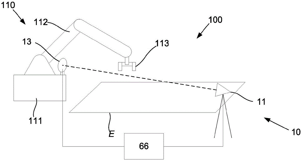
图1A是用于在环境中执行交互的具有机器人组件以及定位和定向跟踪系统的系统的示意图;Figure 1A is a schematic diagram of a system with robotic components and localization and orientation tracking systems for performing interactions in an environment;
图1B是具有跟踪底座和跟踪目标的定位和定向跟踪系统的第一示例的示意性透视图;1B is a schematic perspective view of a first example of a position and orientation tracking system with a tracking base and a tracking target;
图1C至图1D是来自图1B的定位和定向跟踪系统的跟踪目标的示意性前视图,其分别示出了具有零度和α度横滚角的目标;FIGS. 1C-1D are schematic front views of a tracked target from the position and orientation tracking system of FIG. 1B , showing targets with roll angles of zero degrees and α degrees, respectively;
图2是用于在定位和定向跟踪系统的第二示例中使用的跟踪底座的示例的示意性透视图;Figure 2 is a schematic perspective view of an example of a tracking mount for use in a second example of a positioning and orientation tracking system;
图3是图2的跟踪底座的内部组成部分的示意图;Fig. 3 is a schematic diagram of the internal components of the tracking base of Fig. 2;
图4是用于在定位和定向跟踪系统的第二示例中使用的跟踪目标的示例的示意性透视图;4 is a schematic perspective view of an example of a tracked target for use in a second example of a positioning and orientation tracking system;
图5是示出图4的跟踪目标的内部组成部分的示意性横截面视图;FIG. 5 is a schematic cross-sectional view showing internal components of the tracking target of FIG. 4;
图6是定位和定向跟踪系统的第三示例的示意性透视图;Figure 6 is a schematic perspective view of a third example of a position and orientation tracking system;
图7是示出图6的跟踪目标的内部组成部分的示意图;以及,FIG. 7 is a schematic diagram illustrating internal components of the tracking target of FIG. 6; and,
图8是用于跟踪物体在环境中的定位和定向的示例过程的流程图。8 is a flowchart of an example process for tracking the location and orientation of objects in an environment.
优选的实施例的详细描述Detailed description of the preferred embodiment
现在将参照图1A至图1D描述用于跟踪物体在环境中的定位和定向的跟踪系统10的示例。An example of a
在该示例中,应当理解,跟踪系统10通常形成用于在环境中执行交互的系统100的一部分。系统100可以包括例如机器人组件110,机器人组件110具有机器人底座111,机器人底座111支撑机器人臂112和被编程为在环境内执行交互的末端执行器113。机器人组件110相对于环境E定位,在该示例中,环境E被示为2D平面,但是在实践中可以是任何配置的3D体积。在使用中,末端执行器113用于在环境E内执行交互,例如执行砌砖、物体操纵等。机器人底座111通常是可移动的机器人底座,其可以例如安装到可以在3-30m之间延伸的吊臂结构等,从而使得末端执行器113能够在大的工作体积内工作。被跟踪的物体可以是机器人组件110的任何部件,包括例如机器人底座111、机器人臂112和末端执行器113。In this example, it should be understood that the
为了清楚起见,应当理解,跟踪系统10通常能够跟踪机器人组件的移动,并且在一个特定示例中,能够跟踪机器人底座相对于环境的移动。在一个示例中,跟踪系统包括通常相对于环境E静态定位的跟踪底座11和安装在机器人底座111上的跟踪目标13,允许机器人底座111相对于环境E的定位和定向被确定。在其他示例中,跟踪器目标13可以定位在机器人组件110的另一部分上,包括例如在机器人部件(例如机器人臂112或末端执行器113)上,使得机器人的至少一部分的定位和定向被测量。For clarity, it should be understood that tracking
术语“交互”旨在指在环境内发生的任何物理交互,并且包括与环境发生的物理交互或在环境上发生的物理交互。示例交互可以包括将材料或物体放置在环境内、从环境中移除材料或物体、移动环境内的材料或物体、修改、操纵或以其他方式与环境内的材料或物体接合、修改、操纵或以其他方式与环境接合等。The term "interaction" is intended to refer to any physical interaction that occurs within the environment, and includes physical interaction with or on the environment. Example interactions may include placing materials or objects within the environment, removing materials or objects from the environment, moving materials or objects within the environment, modifying, manipulating, or otherwise engaging with, modifying, manipulating, or Engage with the environment in other ways, etc.
术语“环境”是用来指在其内或其上执行交互的任何位置、区块、区域或体积。环境的类型和性质将根据优选的实现方式而变化,并且环境可以是离散的物理环境,和/或可以是逻辑物理环境,仅仅因为其是发生交互所在的体积而从周围环境中描绘出来。环境的非限制性示例包括建筑物或施工现场、交通工具的部件,例如轮船甲板或卡车的装载托盘、工厂、装载现场、地面工作区域等。The term "environment" is used to refer to any location, region, area or volume within or on which an interaction is performed. The type and nature of the environment will vary depending on the preferred implementation, and the environment may be a discrete physical environment, and/or may be a logical physical environment delineated from the surrounding environment simply because it is the volume in which interaction occurs. Non-limiting examples of environments include buildings or construction sites, parts of vehicles such as ship decks or truck loading pallets, factories, loading sites, ground work areas, and the like.
机器人臂是可编程机械操纵器。在本说明书中,机器人臂包括多轴关节臂、并联运动学机器人(例如Stewart平台、Delta机器人)、球形几何机器人、笛卡尔机器人(具有直线运动的正交轴机器人)等。Robotic arms are programmable mechanical manipulators. In this specification, a robot arm includes a multi-axis articulated arm, a parallel kinematics robot (such as a Stewart platform, a Delta robot), a spherical geometry robot, a Cartesian robot (orthogonal axis robot with linear motion), and the like.
吊臂是细长支撑结构,例如具有或不具有杆或铲斗、具有或不具有伸缩元件的回转吊臂、伸缩吊臂、伸缩铰接式吊臂。示例包括起重机吊臂、推土机吊臂、卡车起重机吊臂,其都具有或都不具有线缆支撑的或线缆加固的元件。吊臂还可以包括高架门架(overheadgantry)结构或悬臂门架(cantilevered gantry)或受控拉伸桁架(吊臂可以不是吊臂,而是多线缆支撑的并联运动学起重机(见PAR系统,拉伸桁架-Chernobyl起重机))或可在空间中平移定位的其他可移动臂。Booms are elongated support structures such as slewing booms, telescopic booms, telescopic articulated booms with or without rods or buckets, with or without telescopic elements. Examples include crane booms, bulldozer booms, truck crane booms, all with or without cable-supported or cable-reinforced elements. Jibs may also include overhead gantry structures or cantilevered gantry or controlled tension trusses (the jib may not be a jib but a parallel kinematic crane supported by multiple cables (see PAR system, Tensile trusses - Chernobyl cranes)) or other movable arms that can be positioned in translation in space.
末端执行器是被设计成与环境交互的在机器人臂的末端处的设备。末端执行器可以包括夹持器、喷嘴、喷砂器、喷枪、扳手、磁铁、焊炬、割炬、锯、铣刀、镂铣刀(routercutter)、液压剪机、激光器、铆接工具等等,并且对这些示例的提及并非旨在进行限制。An end effector is a device at the end of a robotic arm that is designed to interact with the environment. End effectors may include grippers, nozzles, blasters, spray guns, wrenches, magnets, welding torches, cutting torches, saws, milling cutters, routercutters, hydraulic shears, lasers, riveting tools, etc., And references to these examples are not intended to be limiting.
应当理解,为了控制机器人组件110将末端执行器113精确地定位在期望的位置处以便在环境内执行交互,必须能够精确地确定机器人组件上参考点的定位和定向。It should be appreciated that in order to control the
在该示例中,跟踪系统10包括被定位于环境中的跟踪底座11和能够安装到物体的跟踪目标13。在使用中,跟踪底座11通过在跟踪底座11和跟踪目标13之间传输的双向光束17以及在跟踪底座11和跟踪目标13之间传输的单向光束31链接到跟踪目标13,所述单向光束31平行于双向光束17。双向光束17(例如激光束)通常从跟踪底座11传输到跟踪目标13。跟踪目标13被配置成将光束反射回跟踪底座11。这使得能够确定跟踪底座11和跟踪目标13之间的距离,并且随着跟踪底座11的摇动(pan)和倾斜,可以确定跟踪目标13的位置。跟踪目标13通常包括用于俯仰和偏航的致动器,以便相互地跟踪跟踪底座11并保持锁定在双向光束17上。In this example, the
单向光束31(或横滚光束)提供横滚角参考。在这点上,跟踪系统10还包括至少一个控制器66,其被配置为确定跟踪目标13相对于跟踪底座11的横滚角,该横滚角至少部分地由从传感器接收的信号来确定,该传感器容纳在跟踪底座11和跟踪目标13中的至少一者中,检测单向光束31。该至少一个控制器66可以是专用的跟踪系统控制器,或者替代地,控制器66可以是机器控制器,其也控制目标所安装到的机器人等的移动。A unidirectional beam 31 (or roll beam) provides a roll angle reference. In this regard, the
该至少一个控制器66通常包括电子处理设备,该电子处理设备结合存储的指令来操作,并且该电子处理设备操作以从跟踪底座和跟踪目标接收信号,处理信号以确定定位和定向数据,并且为诸如马达等的致动器生成控制信号以执行光束操纵(steering)并且保持底座和目标之间的相应光束的链接。电子处理设备可以包括任何电子处理设备,例如微处理器、微芯片处理器、逻辑门配置、可选地与实现逻辑(例如FPGA(现场可编程门阵列))相关联的固件、或者任何其他电子设备、系统或布置。The at least one
典型地,传感器是定位位移传感器(PDS),它是一种模拟设备,提供与入射激光束的中心在其表面上的位置成比例的实时信号。商业上可获得的PDS具有良好的重复性和模拟分辨率,具有低噪声且优于传感器尺寸的0.1%的精度。通过使用小传感器,定位精度高。PDS测量结果可由控制系统通过ADC(模数转换器)读取,ADC可在控制器的循环控制速率下操作,从而有效地消除延时。Typically, the sensor is a Position Displacement Sensor (PDS), an analog device that provides a real-time signal proportional to the position of the center of the incident laser beam on its surface. Commercially available PDSs have good repeatability and analog resolution with low noise and an accuracy better than 0.1% of sensor size. By using small sensors, the positioning accuracy is high. The PDS measurements can be read by the control system through an ADC (analog-to-digital converter), which can operate at the loop-controlled rate of the controller, effectively eliminating delays.
上述跟踪系统10提供了改进的横滚角测量,该改进的横滚角测量提供了许多优点。首先,增加了横滚的定向测量精度,使得能够根据传感器尺寸实现大约0.001度或更优的精度。这又可以在40m半径的整个工作包络内实现大约0.2mm的绝对定位精度。这显著优于当前可获得的激光跟踪系统能够达到的0.1或0.01度。这一点很重要,因为末端执行器离跟踪目标的安装定位越远,由于定向测量误差导致的末端执行器定位误差就越大。The
此外,可以以至少1kHz提供这种精确程度的测量,因为横滚测量结果可以以控制器的循环速率读取,控制器的循环速率例如可以具有1ms的时钟周期。因此,可以实现具有最小延时的非常精确和连续的横滚测量,这使得能够实现实时动态运动补偿。为了控制在可移动吊臂的末端上的机器人末端执行器定位和定向的动态运动补偿,需要具有低延时(或延迟)或优选无延时(或延迟)的快速数据。通过减小延时,运动补偿没有太大的滞后,并提供及时的定位和定向校正。最后,跟踪系统还能够提供低噪声的测量数据,使得运动补偿系统不会受到振动噪声的影响。Furthermore, measurements of this degree of accuracy can be provided at least 1 kHz because roll measurements can be read at the controller's loop rate, which can have a clock period of 1 ms, for example. As a result, very precise and continuous roll measurement with minimal time delay is possible, which enables real-time dynamic motion compensation. To control dynamic motion compensation of robot end effector positioning and orientation on the end of a movable boom, fast data with low or preferably no latency (or delay) is required. By reducing latency, motion compensation does not have much lag and provides timely positioning and orientation corrections. Finally, the tracking system can also provide low-noise measurement data, so that the motion compensation system is not affected by vibration noise.
现在将描述另外的许多特征。A number of additional features will now be described.
在一个示例中,传感器测量单向光束相对于传感器的表面上的基准定位的位移。然后,从所测量的位移确定横滚角。如果只需要测量小的横滚角(例如几度),那么可以使用足够小的传感器(例如PDS)来提供大约0.001度或更优的高精度测量。然而,在目标可能经历大量横滚的系统中,将需要更大的PDS,并且如果PDS不延伸通过360度,则会限制可以测量到的横滚角。如果使用大的PDS,也会降低横滚角精度。然而,对于横滚为最小的系统,这种实现方式是简单直接的,因为它需要其他布置需要的任何移动部件,这将在下面描述。In one example, the sensor measures the displacement of the unidirectional beam relative to a fiducial positioned on the surface of the sensor. Then, the roll angle is determined from the measured displacement. If only small roll angles (eg a few degrees) need to be measured, then a sensor small enough (eg PDS) can be used to provide high accuracy measurements on the order of 0.001 degrees or better. However, in systems where the target is likely to experience a large amount of roll, a larger PDS will be required, and if the PDS does not extend through 360 degrees, will limit the roll angle that can be measured. If a large PDS is used, it will also degrade roll angle accuracy. However, for systems where roll is minimal, this implementation is straightforward as it requires any moving parts that other arrangements would require, as will be described below.
在图1B至图1D所示的示例中,单向光束31穿过光学安装件37,该光学安装件37安装在跟踪底座11和跟踪目标13中的至少一者(在该实例中是跟踪目标13)上,用于围绕与双向光束17同轴的旋转轴进行受控旋转,并且其中,控制器被配置成控制光学安装件37的旋转,以便保持在跟踪底座11和跟踪目标13之间传输的单向光束31的链接,并且其中,受控旋转的角度由控制器确定,并且从受控旋转的角度导出横滚角数据。In the example shown in FIGS. 1B-1D , the
典型地,传感器容纳在光学安装件中,并且其中,传感器提供与单向光束入射在传感器的表面上的位置成比例的信号。在图1C中,跟踪目标13被示为处于名义上的直立定位,其中光学安装件37相对于跟踪头单元57的曲面39居中设置,光学安装件37围绕该曲面39旋转。该定位指示零横滚角。在图1D中,跟踪目标13被示为具有横滚角α。可以看出,当跟踪目标13横滚时(例如,由于其所安装到的物体经历横滚),光学安装件37围绕与双向光束17重合的横滚轴沿相反方向旋转。光学安装件37旋转以确保单向光束37始终保持在传感器的中心,这使PDS归零。Typically, the sensor is housed in an optical mount, and wherein the sensor provides a signal proportional to the position of the unidirectional light beam incident on the surface of the sensor. In FIG. 1C the tracking
典型地,控制器从传感器接收信号,处理信号以确定单向光束入射在传感器表面上的位置;并且,使光学安装件根据经处理的信号围绕旋转轴旋转,以便将单向光束定位在传感器表面的中心,并保持在跟踪底座和跟踪目标之间传输的单向光束的链接。Typically, the controller receives a signal from the sensor, processes the signal to determine where the unidirectional beam is incident on the sensor surface; and, rotates the optical mount about an axis of rotation based on the processed signal to position the unidirectional beam on the sensor surface and maintain the link of the unidirectional beam transmitted between the tracking base and the tracking target.
在这点上,马达可以耦合到光学安装件,并且其中,控制器被配置成控制马达以旋转光学安装件并且将光学安装件与单向光束对准。In this regard, the motor may be coupled to the optical mount, and wherein the controller is configured to control the motor to rotate the optical mount and align the optical mount with the unidirectional light beam.
指示横滚角的受控旋转的角度可以以至少两种方式来确定。在一个示例中,所述受控旋转的角度由所述控制器从角度编码器中确定,并且横滚角数据从所述受控旋转的角度导出。替代地,所述受控旋转的角度从马达控制数据来确定。此外,所述受控旋转的角度可以包括由来自传感器的测量信号确定的跟随误差校正。The angle indicative of the controlled rotation of the roll angle can be determined in at least two ways. In one example, the angle of controlled rotation is determined by the controller from an angle encoder, and roll angle data is derived from the angle of controlled rotation. Alternatively, the angle of the controlled rotation is determined from motor control data. Furthermore, the angle of the controlled rotation may include a following error correction determined from the measurement signal from the sensor.
应当理解,优选地,跟踪底座是激光跟踪器,并且跟踪目标是主动目标,该主动目标被配置成跟踪跟踪底座以便保持在激光跟踪器和主动目标之间传输的双向光束的链接。It will be appreciated that preferably the tracking base is a laser tracker and the tracking target is an active target configured to track the tracking base so as to maintain a link of bi-directional light beams transmitted between the laser tracker and the active target.
典型地,跟踪底座包括围绕彼此垂直的两个轴安装到第一底座的第一头部单元,并且其中,跟踪目标包括围绕彼此垂直的两个轴安装到第二底座的第二头部单元,其中,两个头部单元中围绕两个轴的旋转由头部单元控制器控制成围绕它们相应的所述两个轴旋转,以保持所述双向光束的链接。第二头部单元围绕其轴旋转以跟随第一头部单元的能力使得例如主动目标能够确定其自身的偏航和俯仰。Typically, the tracking base comprises a first head unit mounted to a first base about two axes perpendicular to each other, and wherein the tracking target comprises a second head unit mounted to a second base about two axes perpendicular to each other, Wherein the rotations of the two head units about the two axes are controlled by the head unit controller to rotate about their respective said two axes, so as to maintain the linkage of the bi-directional light beams. The ability of the second head unit to rotate about its axis to follow the first head unit enables eg an active target to determine its own yaw and pitch.
在一个示例中,第一头部单元围绕垂直于双向光束的方向延伸的第一万向节轴安装到第一万向节,第一万向节围绕垂直于第一万向节轴延伸的第一底座轴安装到第一底座;并且第二头部单元围绕垂直于双向光束的方向延伸的第二万向节轴安装到第二万向节,第二万向节围绕垂直于所述第二万向节轴延伸的第二底座轴安装到第二底座。虽然可以使用万向节系统(gimbal system),但在实践中任何合适的枢转安装件都可以用来安装跟踪底座和跟踪目标的相应头部单元。In one example, the first head unit is mounted to the first gimbal around a first gimbal axis extending perpendicular to the direction of the bidirectional light beam, the first gimbal around a first gimbal axis extending perpendicular to the first gimbal axis a base shaft mounted to the first base; and a second head unit mounted to a second gimbal around a second gimbal shaft extending perpendicular to the direction of the bidirectional light beam, the second gimbal around a second The second base shaft from which the cardan shaft extends is mounted to the second base. Although a gimbal system may be used, in practice any suitable pivot mount may be used to mount the tracking base and corresponding head unit of the tracking target.
设想了跟踪系统的许多不同排列。Many different permutations of tracking systems are envisioned.
在一种布置中,单向光束源位于跟踪底座中以产生所述单向光束,并且所述光学安装件位于跟踪目标上,该光学安装件还包括所述传感器以检测单向光束。In one arrangement, the unidirectional beam source is located in the tracking mount to generate the unidirectional beam and the optical mount is located on the tracking target, the optical mount further comprising the sensor to detect the unidirectional beam.
在另一种布置中,单向光束源位于跟踪目标中以产生单向光束,并且所述光学安装件位于跟踪底座上,该光学安装件还包括所述传感器以检测单向光束。In another arrangement, the unidirectional beam source is located in the tracking target to generate the unidirectional beam and the optical mount is located on the tracking mount, the optical mount also including the sensor to detect the unidirectional beam.
在另一种布置中,单向光束源位于光学安装件中以产生单向光束,并且光学安装件位于跟踪目标上,并且跟踪底座包括所述传感器以检测单向光束。In another arrangement, the unidirectional beam source is located in the optical mount to generate the unidirectional beam, and the optical mount is located on the tracking target, and the tracking mount includes the sensor to detect the unidirectional beam.
在又一种布置中,单向光束源位于光学安装件中以产生单向光束,并且光学安装件位于跟踪底座上,并且跟踪目标包括所述传感器以检测单向光束。因此,从上面将会理解,单向光束源(即横滚光束激光器)可以位于跟踪底座或跟踪目标中,并且光学安装件和传感器同样如此。In yet another arrangement, the unidirectional beam source is located in the optical mount to generate the unidirectional beam, and the optical mount is located on the tracking mount, and the tracking target includes the sensor to detect the unidirectional beam. Thus, it will be appreciated from the above that the unidirectional beam source (ie roll beam laser) may be located in the tracking mount or tracking target, as well as the optical mount and sensor.
光学安装件也可以以多种方式布置。它可以是被配置成围绕一个头部单元的曲面旋转的壳体,或者替代地,光学安装件可以位于环形构件上,该环形构件被布置成围绕双向光束的传输轴线进行受控旋转。Optical mounts can also be arranged in a variety of ways. It may be a housing configured to rotate about the curved surface of a head unit, or alternatively the optical mount may be located on an annular member arranged for controlled rotation about the transmission axis of the bi-directional light beam.
在另一种广泛的形式中,本发明提供了一种使用跟踪系统来跟踪物体在环境中的定位和定向的方法,该跟踪系统包括:被定位于环境中的跟踪底座;能够安装到物体的跟踪目标,其中在使用中,跟踪底座通过以下方式链接到跟踪目标:在其间传输的双向光束;以及在其间传输的单向光束,所述单向光束平行于双向光束;并且其中,该方法包括在至少一个控制器中:接收来自传感器的信号,该传感器容纳在跟踪底座和跟踪目标中的至少一者中,该传感器检测单向光束;以及至少部分地使用所接收的信号来确定跟踪目标相对于跟踪底座的横滚角。In another broad form, the invention provides a method of tracking the position and orientation of an object in an environment using a tracking system comprising: a tracking mount positioned in the environment; a tracking target, wherein, in use, the tracking mount is linked to the tracking target by: a bidirectional light beam transmitted therebetween; and a unidirectional light beam transmitted therebetween, said unidirectional light beam being parallel to the bidirectional light beam; and wherein the method comprises In at least one controller: receiving a signal from a sensor housed in at least one of the tracking base and the tracking target, the sensor detecting a unidirectional light beam; and using at least in part the received signal to determine the relative for tracking the roll angle of the base.
在一个示例中,该方法还包括在该至少一个控制器中:使用所接收的信号来确定单向光束相对于传感器的表面上的基准定位的位移;以及,使用所确定的位移来确定横滚角。In one example, the method further includes, in the at least one controller: using the received signal to determine a displacement of the unidirectional beam relative to a reference location on the surface of the sensor; and, using the determined displacement to determine a roll horn.
在另一个示例中,跟踪系统包括光学安装件,单向光束穿过该光学安装件,该光学安装件安装在跟踪底座和跟踪目标中的至少一者上,该光学安装件容纳传感器并被配置用于围绕与双向光束同轴的旋转轴进行受控旋转,并且其中,该方法还包括在该至少一个控制器中:处理从传感器接收的信号以确定单向光束入射在传感器表面上的位置;以及,使光学安装件根据经处理的信号围绕旋转轴旋转,以便将单向光束定位在传感器表面的中心,并保持在跟踪底座和跟踪目标之间传输的单向光束的链接。In another example, the tracking system includes an optical mount through which the unidirectional light beam passes, the optical mount mounted on at least one of the tracking base and the tracking target, the optical mount housing the sensor and configured for controlled rotation about an axis of rotation coaxial with the bi-directional beam, and wherein the method further includes in the at least one controller: processing signals received from the sensor to determine a location where the unidirectional beam is incident on the sensor surface; And, rotating the optical mount about the axis of rotation based on the processed signal to center the unidirectional beam on the sensor surface and maintain a link of the unidirectional beam transmitted between the tracking base and the tracking target.
现在将进一步详细地描述本发明的优选实施例。所有实施例都是改进的定位和定向测量装置,其具有激光跟踪器11形式的第一头部单元和主动目标传感器13形式的第二头部单元,结合了改进的横滚角测量。激光跟踪器11具有初级激光器15,初级激光器15生成初级激光束17,初级激光束17被主动目标传感器13反射回来,形成双向激光束。参考图3,激光跟踪器11包括单光束干涉仪19和反射镜21,其将初级激光束17的一部分反射到条纹计数器23,从条纹计数器23获取距离数据。50%分束器25将初级激光束17的一部分发送到双轴横向效应光电二极管或双轴定位位移传感器27,以导出用于“操纵”激光跟踪器初级激光束17的数据,以便精确地瞄准主动目标传感器13。Preferred embodiments of the present invention will now be described in further detail. All embodiments are improved positioning and orientation measurement devices with a first head unit in the form of a
激光跟踪器11还具有第二激光器29,第二激光器29被布置成将与初级激光束17平行的单向第二激光束31发送到位于主动目标传感器13上的横滚定位位移传感器33。在第一实施例中,横滚定位位移传感器33包括位于壳体37内的定位位移传感器35,壳体37被安装在用于旋转的曲面39上,使得定位位移传感器35随着初级激光束17旋转。安装在曲面39上的壳体37围绕与初级激光束17在被正确对准以由主动目标传感器13反射回来时的行进线相同的轴线(即,传输轴线或横滚轴)旋转。曲面表示壳体37围绕其、围绕传输轴线进行120度旋转的表面,这使得该实施例适用于在横滚感测被限制为与壳体37的中心定位成正60度或负60度的应用中使用。角度编码器产生信号以指示壳体37被设置的角度,从而提供主动目标传感器13的横滚角测量结果。The
激光跟踪器11被支撑在轭41上,轭41在支撑件43上绕基本上竖直的航向轴线45旋转。轭41可旋转地支撑绕水平高度轴线49旋转的头部47。头部47包含初级激光器15、单光束干涉仪19和反射镜21、条纹计数器23、50%分束器25和传感器27,并支撑第二激光器29。The
激光跟踪器初级光束光学器件包括初级激光器15以及单光束干涉仪19和条纹计数器23,但是作为单光束干涉仪19和条纹计数器23的替代方案,可以包括飞行时间ADM(自动测距仪),或者两者的组合。激光跟踪器初级光束光学器件还包括50%分束器25和传感器27,如上面所讨论的,它们可以从双轴PDS(定位位移传感器)或双轴横向效应光电二极管中选择,但是作为另一种替代方案,可以利用具有相关联的电路的CCD或CMOS传感器阵列。从传感器导出的数据被处理并被用于控制无刷AC伺服马达50,以相对于支撑件43移动轭41,并相对于轭41移动头部47。与伺服马达50相关联的角度编码器测量旋转的角度,并且除了从条纹计数器23数据的分析中确定的随后能够确定目标的定位的距离数据之外,该数据还用于提供姿态和航向数据。尽管无刷AC伺服马达50是最优选的,但是替代实施例可以利用DC伺服马达或步进马达或其他合适的驱动马达。The laser tracker primary beam optics comprise a
图2中示出了激光跟踪器11的替代实施例。这与图1B所示的激光跟踪器的不同之处仅在于轭41和头部47的更紧凑的形状和配置。An alternative embodiment of a
在激光跟踪器11的两种布置中,横滚激光器(roll laser)29设置有校准装置,以使其光束31平行于初级激光束17,这将是在制造期间进行调整的设置,而不期望在现场进行调整。In both arrangements of the
往回参考图1B,主动目标传感器13具有安装到要被跟踪的目标对象的底座51(例如图1A中所示的机器人底座111)。底座51可旋转地支撑绕第一轴线55旋转的轭53。轭53具有U形夹(clevis),其支撑头部57用于绕垂直于第一轴线55的第二轴线59旋转。头部57具有位于其顶部的曲面39。Referring back to FIG. 1B , the
头部57支撑内部装备以感测初级激光束17。在图5和图7中示出了这两个不同实施例的细节。参考图5,在一种布置中,典型地,这可以包括具有针孔63的反射镜61,位于反射镜61后面的是双轴定位位移传感器65。反射镜61可以将初级激光束17的大部分反射回激光跟踪器11,同时初级激光束17的一些穿过针孔63到达双轴定位位移传感器65。来自定位位移传感器65的信号被馈送到控制器66,控制器66控制无刷AC伺服马达来控制轭53的定位和头部57的定位,使得反射镜61被对准以将初级激光束17反射回激光跟踪器11。
在图4和图5中示出了主动目标传感器13的实施例。主动目标传感器13具有底座51,底座51安装到要被跟踪的目标对象(未示出)。底座51可旋转地支撑围绕第一轴线55旋转的轭53。轭53具有U形夹,其支撑头部57用于围绕垂直于第一轴线55的第二轴线59旋转。初级激光束17穿过窗口71到达用于感测和反射它的内部装备,该内部装备包括具有针孔63的反射镜61,位于该反射镜61后面的是双轴定位位移传感器65,如图5所示。窗口71安装在圆柱形外壳73的暴露端,环形外壳75被安装成围绕该圆柱形外壳73进行受控旋转,该环形外壳75具有供单向第二激光束31穿过以到达定位位移传感器35的窗口77。环形伺服马达79在精确定位单向第二激光束31的定位位移传感器35的反馈控制下使环形外壳75围绕圆柱形外壳73横滚。环形伺服马达具有无刷外转式配置(brushless outrunnerconfiguration)(在CD驱动马达中的以及在模型汽车和模型飞行器等应用中使用的无刷电动马达中的一种众所周知的配置),并且包括偶数个永磁体81和多个(三的倍数个)电磁线圈83,这些永磁体81附接到环形外壳75的内部并围绕该内部延伸(环形外壳75优选是铁磁性的并且由钢构成),以交替磁极方式布置(即从布置成N极在内侧、S极在外侧的磁体开始,然后相邻的磁体布置成S在内侧、N在外侧,以此类推),电磁线圈83被示意性地示出为缠绕在软铁或硅钢叠片87上的线圈85。在该应用中,典型的环形伺服马达可以具有18个永磁体和9个电磁线圈,这些电磁线圈被布置成三组,每组三个线圈。角度编码器89包括安装在环形外壳75的背面上的编码器环91和安装在支撑件95上的编码器读取头93,角度编码器89向控制器66提供精确的横滚角数据。Exemplary embodiments of an
控制器66使用来自定位位移传感器35的信号作为反馈信号来控制伺服马达79的运动,以使环形外壳75绕其横滚轴横滚,从而使来自定位位移传感器35的信号归零。与环形外壳75相关联的角度编码器89向控制器66提供横滚角测量值。在其最简单的形式中,横滚轴的速度与定位位移传感器35信号成比例,使得当来自定位位移传感器35的值增加时,横滚轴的速度与应用于反馈的比例增益成比例地增加,从而将横滚轴和定位位移传感器35移向其零位置。在反馈控制的更复杂形式中,可以在控制回路中应用差分增益和积分增益,以使跟随误差最小化。The
基于来自定位位移传感器35的测量,通过在角度编码器角度上加上跟随误差校正,可以使横滚角测量更精确。定位位移传感器35可以通过围绕横滚轴旋转定位位移传感器35并将定位位移传感器35信号与编码器角度相关联来进行校准。校准通常是在制造期间或在实验室中进行的,而不是在现场条件下进行的。The roll angle measurement can be made more accurate by adding a following error correction to the angle encoder angle based on the measurements from the
图1A-1D、图4和图5中所示的主动目标传感器13的布置在实践中可能难以实现,因为必须同时对准激光跟踪器11和主动目标传感器13。激光跟踪器11必须将双向光束17指向反射镜61,反射镜61必须被对准以将双向光束17反射回激光跟踪器11。这使得设置变得困难。可选的摄像机(未示出)可以装配到激光跟踪器11或主动目标传感器13,以帮助设置对准。这些摄像机可以连接到计算机视觉处理器,以进行自动识别并将激光跟踪器17与主动目标传感器13对准,反之亦然。一种更容易设置的替代方案需要用如图6和图7中所示的实施例中示出的后向反射器来替换反射镜61。The arrangement of
参考图6,示出了定位和定向跟踪系统的另一个实施例。定位和定向跟踪系统具有激光跟踪器11形式的第一头部单元和主动目标传感器13形式的第二头部单元。该实施例与前述实施例的不同之处在于,横滚角测量被结合在激光跟踪器11中。Referring to Figure 6, another embodiment of a position and orientation tracking system is shown. The positioning and orientation tracking system has a first head unit in the form of a
激光跟踪器11具有初级激光器15,初级激光器15生成初级激光束17,初级激光束17被主动目标传感器13反射回来,形成双向激光束。如图3所示,用于初级激光束17的内部布置与第一实施例和第二实施例中的相同。然而,第二激光器29被布置成发送与初级激光束17平行的单向第二激光束31,第二激光器29被安装在环形外壳97中,环形外壳97被安装成通过无刷AC伺服马达进行旋转。环形外壳97具有相关联的用于向控制器66发送横滚角数据的角度编码器89。第二激光束31被传输到位于主动目标传感器13中的横滚定位位移传感器33。一旦初级激光束17被激光跟踪器11和主动目标传感器13锁定,环形外壳97就必须旋转到正确的角度,以便横滚定位位移传感器33检测第二激光束31。The
与环形外壳97相关联的角度编码器89产生信号以指示环形外壳81设置的角度,从而提供对主动目标传感器13的横滚角测量。
激光跟踪器11被支撑在轭41上,轭41在支撑件43上围绕基本上竖直的航向轴45旋转。轭41可旋转地支撑围绕水平高度轴49旋转的头部47。头部47包含初级激光器15、单光束干涉仪19和反射镜21、条纹计数器23、50%分束器25和传感器27,并将第二激光器29支撑在环形外壳97中。The
主动目标传感器13具有用于感测初级激光束17的替代布置,该替代布置包括针孔后向反射器99,双轴定位位移传感器92位于针孔后向反射器99之后。在替代实施例中,针孔后向反射器99可以用五棱镜代替。The
来自定位位移传感器92的信号被馈送到控制器66,控制器66控制步进马达来控制轭53的定位和头部57的定位,使得后向反射器99被对准以将初级激光束17反射回激光跟踪器11。从传感器27导出的数据由控制器66处理,并被用于控制无刷AC伺服马达50或DC伺服马达或步进马达或其他合适的驱动马达,以相对于支撑件43移动轭41,并相对于轭41移动头部47。与伺服马达50相关联的角度编码器测量旋转的角度,并且除了从条纹计数器23数据的分析中确定的距离数据之外,该数据还用于提供姿态和航向数据。轭53的定位和头部57的定位被定向成通过将在定位位移传感器92上的光束17调零而指向激光跟踪器11,并且来自角度编码器的数据将头部57的俯仰和偏航数据提供回控制器66。与定位位移传感器92和后向反射器87中的针孔的对准相关的指向方向的对准是在制造期间被校准的,并且通常不进行现场调整。双向激光束17被后向反射器99反射回激光跟踪器11。图7中所示的这种替代布置的优点在于,在头部57被定向成精确地往回指向激光跟踪器11之前,激光跟踪器11可以容易地对准以跟踪后向反射器99。一旦初级激光束17找到定位位移传感器92,并且在通过控制轭53的定位和头部57的定位的步进马达来对准头部57之前,使得后向反射器99被精确地对准以将初级激光束17反射回激光跟踪器11,初级激光束17以准确的直角入射到定位位移传感器89上并入射在其准确的中心位置处,头部57相对于图7所示的光束17和31的角度被显示在适当的位置。The signal from the
可选的摄像机(未示出)可以装配到激光跟踪器11或主动目标传感器13,以帮助初始设置对准。这些摄像机可以连接到计算机视觉处理器,以进行自动识别并将激光跟踪器17与主动目标传感器13对准,反之亦然。An optional camera (not shown) may be fitted to the
激光定位位移传感器可以在市场上购买到(例如从Hamar购买),或者作为分立的光学部件和硅芯片(例如来自On-Trak Photonics的)。定位位移传感器33、35设置有调整它们距初级光束轴的检测半径的装置,以精确地匹配横滚轴激光器距初级光束激光器的距离(或半径)R。Laser positioning displacement sensors are commercially available (eg from Hamar), or as discrete optical components and silicon chips (eg from On-Trak Photonics). The
现在参考图8,现在将描述一种跟踪物体在环境中的定位和定向的方法。Referring now to FIG. 8, a method of tracking the position and orientation of objects in an environment will now be described.
在该示例中,在步骤200,该方法包括在跟踪底座和跟踪目标之间传输双向光束。典型地,跟踪底座包括双向光束源,其朝向目标发射光束,目标将光束反射回跟踪底座。跟踪底座和跟踪目标都包括操控光束的致动器和通常位于目标中的反射镜,以保持在底座和目标之间的双向光束链接。In this example, at
在步骤210,该方法包括在跟踪底座和目标之间传输单向光束。典型地,跟踪底座包括单向光束源,其朝向目标发射单向光束,确保单向光束平行于双向光束。单向光束入射到被容纳在目标(或底座,如果单向光束源位于目标中)中的传感器(例如,定位位移传感器)上。At
在步骤220,至少一个控制器从检测单向光束的传感器接收信号。传感器提供与单向光束入射到传感器的表面上的位置成比例的信号。当光束入射到传感器的中心时,PDS将归零。At
最后,在步骤230,该至少一个控制器至少部分地使用所接收的信号来确定横滚角。在这点上,信号可以直接指示横滚角,例如当传感器测量单向光束相对于其表面上的基准定位的位移并且从测量到的位移来确定横滚角的情况。在另一个示例中,信号被用作反馈,以可控地旋转光学外壳,传感器设置在该光学外壳中,该光学外壳旋转以便在目标横滚时使PDS归零。然后,从光学安装件的受控旋转量来确定横滚角。Finally, at
因此,在至少一个上述示例中,提供了一种跟踪系统,该跟踪系统为工业和建筑机器人的动态测量和控制(特别是那些具有主动或动态运动补偿和稳定的动态测量和控制)提供了优点。该跟踪系统提供了主动目标传感器的精确实时横滚角测量,克服了现有技术的不足,并且使得能够以至少0.001度的精度以1kHz来测量横滚角,这有助于在40m半径的整个工作包络内实现至少0.2mm的机器人末端执行器的绝对定位精度。横滚角测量可以连续进行,并且具有最小的延时,因此使得跟踪系统适用于需要动态运动补偿的机器人系统。Thus, in at least one of the above examples, a tracking system is provided that provides advantages for dynamic measurement and control of industrial and construction robots, particularly those with active or dynamic motion compensation and stabilization . The tracking system provides accurate real-time roll angle measurement from active target sensors, overcomes deficiencies of existing technologies, and enables roll angle to be measured at 1 kHz with an accuracy of at least 0.001 degrees, which facilitates roll angle measurement over the entire 40m radius. The absolute positioning accuracy of the robot end effector at least 0.2mm is achieved within the working envelope. Roll angle measurement can be performed continuously with minimal delay, thus making the tracking system suitable for robotic systems requiring dynamic motion compensation.
在以下专利出版物和共同待审申请中描述了申请人技术的进一步细节:US8166727、PCT/AU2008/001274、PCT/AU2008/001275、PCT/AU2017/050731、PCT/AU2017/050730、PCT/AU2017/050728、PCT/AU2017/050739、PCT/AU2017/050738、PCT/AU2018/050698、AU2017902625、AU2017903310、AU2017903312、AU2017904002、AU2017904110、PCT/AU2018/050698、AU2018902566、AU2018902557、PCT/AU2018/050733、PCT/AU2018/050734、PCT/AU2018/050740、PCT/AU2018/050737和PCT/AU2018/050739,这些文件的内容通过交叉引用被并入本文。Further details of applicants' technology are described in the following patent publications and co-pending applications: US8166727, PCT/AU2008/001274, PCT/AU2008/001275, PCT/AU2017/050731, PCT/AU2017/050730, PCT/AU2017/ 050728, PCT/AU2017/050739, PCT/AU2017/050738, PCT/AU2018/050698, AU2017902625, AU2017903310, AU2017903312, AU2017904002, AU2017904110, PCT/AU20 18/050698, AU2018902566, AU2018902557, PCT/AU2018/050733, PCT/AU2018/ 050734, PCT/AU2018/050740, PCT/AU2018/050737 and PCT/AU2018/050739, the contents of which are incorporated herein by cross-reference.
在整个本说明书和随附的权利要求中,除非上下文另有要求,否则措辞“包括(comprise)”以及变型例如“包括(comprises)”或“包括(comprising)”,将被理解为暗示包括陈述的整体或整体的组或步骤但不排除任何其他的整体或整体的组。Throughout this specification and the appended claims, unless the context requires otherwise, the word "comprise", and variations such as "comprises" or "comprising", will be read to imply that the statement comprises whole or group of wholes or steps without excluding any other whole or group of wholes.
本领域的技术人员将认识到,多种变型和修改将变得明显。对本领域的技术人员变得明显的所有的这样的变型和修改应当被认为落在本发明在描述之前宽泛地表现的精神和范围内。Those skilled in the art will recognize that various changes and modifications will become apparent. All such variations and modifications which become apparent to those skilled in the art are considered to be within the spirit and scope of the invention as broadly expressed before the description.
Claims (42)
Applications Claiming Priority (3)
| Application Number | Priority Date | Filing Date | Title |
|---|---|---|---|
| AU2017903310 | 2017-08-17 | ||
| AU2017903310A AU2017903310A0 (en) | 2017-08-17 | Laser Tracker with Improved Roll Angle Measurement | |
| PCT/AU2018/050873 WO2019033170A1 (en) | 2017-08-17 | 2018-08-16 | Laser tracker with improved roll angle measurement |
Publications (2)
| Publication Number | Publication Date |
|---|---|
| CN111226090A CN111226090A (en) | 2020-06-02 |
| CN111226090B true CN111226090B (en) | 2023-05-23 |
Family
ID=65361640
Family Applications (1)
| Application Number | Title | Priority Date | Filing Date |
|---|---|---|---|
| CN201880067520.0A Active CN111226090B (en) | 2017-08-17 | 2018-08-16 | Laser tracker with improved roll angle measurement |
Country Status (6)
| Country | Link |
|---|---|
| US (1) | US11656357B2 (en) |
| EP (1) | EP3669138B1 (en) |
| CN (1) | CN111226090B (en) |
| AU (1) | AU2018317941B2 (en) |
| SA (1) | SA520411375B1 (en) |
| WO (1) | WO2019033170A1 (en) |
Families Citing this family (21)
| Publication number | Priority date | Publication date | Assignee | Title |
|---|---|---|---|---|
| BR112019000728B1 (en) | 2016-07-15 | 2023-03-28 | Fastbrick Ip Pty Ltd | VEHICLE INCORPORATING BRICK LAYING MACHINE |
| WO2018009980A1 (en) | 2016-07-15 | 2018-01-18 | Fastbrick Ip Pty Ltd | Boom for material transport |
| EP3649616B1 (en) | 2017-07-05 | 2025-01-08 | Fastbrick IP Pty Ltd | Real time position and orientation tracker |
| WO2019033165A1 (en) | 2017-08-17 | 2019-02-21 | Fastbrick Ip Pty Ltd | Interaction system configuration |
| CN111212799B (en) | 2017-10-11 | 2023-04-14 | 快砖知识产权私人有限公司 | Machine for conveying objects and multi-compartment carousel for use therewith |
| EP3823796A4 (en) | 2018-07-16 | 2022-04-27 | Fastbrick IP Pty Ltd | ACTIVE DAMPER SYSTEM |
| AU2019305681A1 (en) | 2018-07-16 | 2021-02-04 | Fastbrick Ip Pty Ltd | Backup tracking for an interaction system |
| AU2019379873B2 (en) | 2018-11-14 | 2024-12-19 | Fastbrick Ip Pty Ltd | Position and orientation tracking system |
| US11698440B2 (en) * | 2019-04-02 | 2023-07-11 | Universal City Studios Llc | Tracking aggregation and alignment |
| CN110726997B (en) * | 2019-10-09 | 2023-11-03 | 秦皇岛达则科技有限公司 | Intelligent laser positioning and tracking system |
| US20230099779A1 (en) * | 2019-10-11 | 2023-03-30 | Leica Geosystems Ag | Metrology system |
| US20230075352A1 (en) * | 2020-02-27 | 2023-03-09 | The Curators Of The University Of Missouri | Method and apparatus for metrology-in-the-loop robot control |
| WO2021174037A1 (en) * | 2020-02-28 | 2021-09-02 | Bly Ip Inc. | Laser alignment device |
| CN111300432B (en) * | 2020-04-08 | 2021-05-11 | 南京工程学院 | A six-dimensional stiffness error compensation system for an industrial robot and its compensation method |
| MX2022013105A (en) | 2020-04-22 | 2023-01-19 | Fastbrick Ip Pty Ltd | Block transfer apparatus and improved clamping assembly for use therewith. |
| US12398574B2 (en) | 2020-07-08 | 2025-08-26 | Fastbrick Ip Pty Ltd | Adhesive application system |
| JP2023142080A (en) * | 2022-03-24 | 2023-10-05 | アイシンシロキ株式会社 | Object detection method and detection device |
| CN114894103B (en) * | 2022-03-30 | 2023-10-10 | 湖北国际物流机场有限公司 | Ultrahigh ship detection system based on laser technology and detection method thereof |
| CN115371545A (en) * | 2022-07-07 | 2022-11-22 | 海宁集成电路与先进制造研究院 | Apparatus and method for attitude measurement and calibration of laser tracker |
| US20250123100A1 (en) * | 2023-10-12 | 2025-04-17 | Trimble Inc. | Multiple single-axis trackers for survey equipment |
| CN118913106B (en) * | 2024-10-09 | 2024-12-06 | 四川拉姆达科技有限公司 | Target ball self-adaptive tracking system and method suitable for complex undulating environment |
Citations (5)
| Publication number | Priority date | Publication date | Assignee | Title |
|---|---|---|---|---|
| CN101476883A (en) * | 2002-07-05 | 2009-07-08 | 瑞尼斯豪公司 | Laser calibration apparatus |
| CN103363902A (en) * | 2013-07-16 | 2013-10-23 | 清华大学 | Dust environment moving object pose detection device and method based on infrared lasers |
| CN103698769A (en) * | 2008-11-17 | 2014-04-02 | 法罗技术股份有限公司 | Device and method for measuring six degrees of freedom |
| CN103959090A (en) * | 2011-12-06 | 2014-07-30 | 莱卡地球系统公开股份有限公司 | Laser Tracker with Position Sensitive Detector for Searching Targets |
| CN105758370A (en) * | 2015-08-24 | 2016-07-13 | 江苏理工学院 | A laser tracking measurement system |
Family Cites Families (339)
| Publication number | Priority date | Publication date | Assignee | Title |
|---|---|---|---|---|
| US1633192A (en) | 1926-03-10 | 1927-06-21 | George D Reagan | Reenforced hollow fracturable building unit |
| US1829435A (en) | 1929-09-21 | 1931-10-27 | Utility Block Inc | Hollow building block |
| US3438171A (en) | 1966-10-24 | 1969-04-15 | Demarest Machine Inc | Bricklaying machine |
| CH536915A (en) | 1970-10-06 | 1973-05-15 | Lingl Hans | Method and device for the prefabrication of wall parts from building elements that can be connected by means of mortar, in particular block bricks |
| US3757484A (en) | 1972-05-15 | 1973-09-11 | Combustion Enginc | Automated bricklaying device |
| USRE28305E (en) | 1972-05-15 | 1975-01-21 | Automated bricklaying device | |
| US3930929A (en) | 1972-11-03 | 1976-01-06 | Lingl Corporation | Apparatus to construct wall panels having openings for doors and windows |
| GB1465068A (en) | 1973-09-20 | 1977-02-23 | Laing & Son Ltd John | Apparatus for the positioning of elements more particularly building elements |
| DE2605970C3 (en) | 1975-02-17 | 1978-07-06 | Cervinter Ab, Malmoe (Schweden) | Device to facilitate the transport of material and the construction of walls made of molded stone, which are closed along their circumference, in particular the lining of converters, metallurgical furnaces, such as blast furnaces, holding devices or the like |
| FR2345367A1 (en) | 1976-03-22 | 1977-10-21 | Sapic | CARROUSEL WITH HORIZONTAL CLOSED CIRCUIT, INCLUDING SEVERAL ARMS JOINTLY WITH A VERTICAL AXIS ROTATING DRUM |
| US4106259A (en) | 1976-10-18 | 1978-08-15 | Taylor Smith Ernest J | Automatic apparatus for laying block units |
| US4245451A (en) | 1976-10-18 | 1981-01-20 | Taylor Smith Ernest J | Automatic method and apparatus for laying block units |
| SE418012B (en) | 1977-10-31 | 1981-04-27 | Cervinter Ab | WORK-EASY APPARATUS FOR TRANSPORTING BUILDING MATERIAL TO A WORKPLACE FROM A HIGHER TO A LOWER LEVEL, SPECIFICALLY DURING CONVERSION INFO |
| US4523100A (en) | 1982-08-11 | 1985-06-11 | R & D Associates | Optical vernier positioning for robot arm |
| LU86114A1 (en) | 1985-10-10 | 1987-06-02 | Wurth Paul Sa | INSTALLATION FOR BRIQUETTING THE INTERIOR WALL OF AN ENCLOSURE |
| US4852237A (en) | 1985-11-09 | 1989-08-01 | Kuka | Method and apparatus for mounting windshields on vehicles |
| LU86188A1 (en) | 1985-12-03 | 1987-07-24 | Wurth Paul Sa | AUTOMATIC OBJECT HANDLER AND ROBOT PROVIDED WITH SUCH A GRAPPLE |
| LU86272A1 (en) | 1986-01-28 | 1987-09-03 | Wurth Paul Sa | AUTOMATED INSTALLATION FOR BRIQUETTING THE INTERIOR WALL OF A SPEAKER |
| US4714339B2 (en) | 1986-02-28 | 2000-05-23 | Us Commerce | Three and five axis laser tracking systems |
| LU86382A1 (en) | 1986-04-01 | 1987-12-07 | Wurth Paul Sa | INSTALLATION FOR BRIQUETTING THE INTERIOR WALL OF AN ENCLOSURE |
| US4790651A (en) | 1987-09-30 | 1988-12-13 | Chesapeake Laser Systems, Inc. | Tracking laser interferometer |
| LU87054A1 (en) | 1987-11-30 | 1989-06-14 | Wurth Paul Sa | INSTALLATION FOR BRIQUETTING THE INTERIOR WALL OF AN ENCLOSURE |
| NO164946C (en) | 1988-04-12 | 1990-11-28 | Metronor As | OPTO-ELECTRONIC SYSTEM FOR EXACTLY MEASURING A FLAT GEOMETRY. |
| US5080415A (en) | 1988-04-22 | 1992-01-14 | Beckman Instruments, Inc. | Robot gripper having auxiliary degree of freedom |
| DE3814810A1 (en) | 1988-05-02 | 1989-11-16 | Bodenseewerk Geraetetech | ACTUATOR FOR ADJUSTING A ROTATING ELEMENT |
| GB8815328D0 (en) | 1988-06-28 | 1988-08-03 | Shell Int Research | Process for reduction of carbonyl compounds |
| US4945493A (en) | 1988-09-26 | 1990-07-31 | Ford Motor Company | Method and system for correcting a robot path |
| LU87381A1 (en) | 1988-11-09 | 1990-06-12 | Wurth Paul Sa | AUTOMATED INSTALLATION FOR LAYING A MASONRY ON A WALL |
| US4952772A (en) | 1988-11-16 | 1990-08-28 | Westinghouse Electric Corp. | Automatic seam tracker and real time error cumulative control system for an industrial robot |
| US4969789A (en) | 1988-12-16 | 1990-11-13 | Searle Gregory P | Machine for handling modular building components |
| JP2786225B2 (en) | 1989-02-01 | 1998-08-13 | 株式会社日立製作所 | Industrial robot control method and apparatus |
| US5049797A (en) | 1990-07-02 | 1991-09-17 | Utah State University Foundation | Device and method for control of flexible link robot manipulators |
| US5737500A (en) | 1992-03-11 | 1998-04-07 | California Institute Of Technology | Mobile dexterous siren degree of freedom robot arm with real-time control system |
| US5321353A (en) | 1992-05-13 | 1994-06-14 | Storage Technolgy Corporation | System and method for precisely positioning a robotic tool |
| JP2769947B2 (en) | 1992-05-15 | 1998-06-25 | 株式会社椿本チエイン | Manipulator position / posture control method |
| US5527145A (en) | 1992-06-03 | 1996-06-18 | Duncan; Joseph C. | Mortaring made easier |
| LU88144A1 (en) | 1992-07-07 | 1994-04-01 | Wurth Paul Sa | Installation for lining an interior wall of an enclosure with brick masonry |
| US5284000A (en) | 1992-11-30 | 1994-02-08 | Redwall Engineering Corp. | Automating bricklaying |
| FR2700532B1 (en) | 1993-01-19 | 1995-03-03 | Potain Sa | Method of hybrid position / force control for manipulator robot. |
| US5497061A (en) | 1993-03-31 | 1996-03-05 | Hitachi, Ltd. | Method of controlling robot's compliance |
| US5413454A (en) | 1993-07-09 | 1995-05-09 | Movsesian; Peter | Mobile robotic arm |
| US5403140A (en) | 1993-10-13 | 1995-04-04 | Storage Technology Corporation | Dynamic sweeping mechanism for a line scan camera |
| US5420489A (en) | 1993-11-12 | 1995-05-30 | Rockwell International Corporation | Robotic end-effector with active system compliance and micro-positioning capability |
| US5557397A (en) | 1994-09-21 | 1996-09-17 | Airborne Remote Mapping, Inc. | Aircraft-based topographical data collection and processing system |
| NO301999B1 (en) | 1995-10-12 | 1998-01-05 | Metronor As | Combination of laser tracker and camera based coordinate measurement |
| US6134507A (en) | 1996-02-06 | 2000-10-17 | Perceptron, Inc. | Method and apparatus for calibrating a non-contact gauging sensor with respect to an external coordinate system |
| US6285959B1 (en) | 1996-02-06 | 2001-09-04 | Perceptron, Inc. | Method and apparatus for calibrating a non-contact gauging sensor with respect to an external coordinate system |
| US5988862A (en) | 1996-04-24 | 1999-11-23 | Cyra Technologies, Inc. | Integrated system for quickly and accurately imaging and modeling three dimensional objects |
| US6681145B1 (en) | 1996-06-06 | 2004-01-20 | The Boeing Company | Method for improving the accuracy of machines |
| US6049377A (en) | 1996-08-16 | 2000-04-11 | Cam C. Lau | Five-axis/six-axis laser measuring system |
| US5838882A (en) | 1996-10-31 | 1998-11-17 | Combustion Engineering, Inc. | Dynamic position tracking and control of robots |
| AU7637698A (en) | 1997-03-24 | 1998-10-20 | Uteda - Dr. Niebuhr Gmbh | Measuring system using laser technique for three-dimensional objects |
| US6310644B1 (en) | 1997-03-26 | 2001-10-30 | 3Dm Devices Inc. | Camera theodolite system |
| US6018923A (en) | 1997-12-16 | 2000-02-01 | Usg Interiors, Inc. | Transition clip for drywall suspension grid |
| US6101455A (en) | 1998-05-14 | 2000-08-08 | Davis; Michael S. | Automatic calibration of cameras and structured light sources |
| IT1303239B1 (en) | 1998-08-07 | 2000-11-02 | Brown & Sharpe Dea Spa | DEVICE AND METHOD FOR POSITIONING A MEASURING HEAD IN A THREE-DIMENSIONAL MEASURING MACHINE WITHOUT CONTACT. |
| US6611141B1 (en) | 1998-12-23 | 2003-08-26 | Howmedica Leibinger Inc | Hybrid 3-D probe tracked by multiple sensors |
| US6330503B1 (en) | 1999-02-22 | 2001-12-11 | Trimble Navigation Limited | Global positioning system controlled staking apparatus |
| US7800758B1 (en) | 1999-07-23 | 2010-09-21 | Faro Laser Trackers, Llc | Laser-based coordinate measuring device and laser-based method for measuring coordinates |
| US6213309B1 (en) | 1999-04-30 | 2001-04-10 | B & H Manufacturing Company, Inc. | Turret feed control apparatus for sorting and distributing articles in a process system |
| US6850946B1 (en) | 1999-05-26 | 2005-02-01 | Wireless Valley Communications, Inc. | Method and system for a building database manipulator |
| WO2000077471A1 (en) | 1999-06-10 | 2000-12-21 | MPT Präzisionsteile GmbH Mittweida | Device for the contactless three-dimensional measurement of bodies and method for determining a co-ordinate system for measuring point co-ordinates |
| US6370837B1 (en) | 1999-08-04 | 2002-04-16 | Anthony B. Mcmahon | System for laying masonry blocks |
| US6166811A (en) | 1999-08-12 | 2000-12-26 | Perceptron, Inc. | Robot-based gauging system for determining three-dimensional measurement data |
| US6429016B1 (en) | 1999-10-01 | 2002-08-06 | Isis Pharmaceuticals, Inc. | System and method for sample positioning in a robotic system |
| DE29918341U1 (en) | 1999-10-18 | 2001-03-01 | Tassakos Charalambos | Device for determining the position of measuring points of a measuring object relative to a reference system |
| SE515374C2 (en) | 1999-10-29 | 2001-07-23 | Abb Flexible Automation As | Method and apparatus for determining an object's coordinates and orientation in a reference coordinate system |
| FR2805350B1 (en) | 2000-02-18 | 2003-07-11 | Scertab Soc Civ Ile D Etudes E | TELEMETRY EQUIPMENT FOR BI- OR THREE-DIMENSIONAL MAPPING OF A VOLUME |
| GB0008303D0 (en) | 2000-04-06 | 2000-05-24 | British Aerospace | Measurement system and method |
| SE0001312D0 (en) | 2000-04-10 | 2000-04-10 | Abb Ab | Industrial robot |
| JP4874499B2 (en) | 2000-07-14 | 2012-02-15 | ロッキード マーティン コーポレイション | System and method for positioning and positioning an ultrasonic signal generator for test purposes |
| US6664529B2 (en) | 2000-07-19 | 2003-12-16 | Utah State University | 3D multispectral lidar |
| KR100780259B1 (en) | 2000-08-25 | 2007-11-28 | 라이카 게오시스템스 아게 | Distance measuring method and device |
| GB0022444D0 (en) | 2000-09-13 | 2000-11-01 | Bae Systems Plc | Positioning system and method |
| US6427122B1 (en) | 2000-12-23 | 2002-07-30 | American Gnc Corporation | Positioning and data integrating method and system thereof |
| CA2348212A1 (en) | 2001-05-24 | 2002-11-24 | Will Bauer | Automatic pan/tilt pointing device, luminaire follow-spot, and 6dof 3d position/orientation calculation information gathering system |
| GB0125079D0 (en) | 2001-10-18 | 2001-12-12 | Cimac Automation Ltd | Auto motion:robot guidance for manufacturing |
| US6873880B2 (en) | 2001-12-26 | 2005-03-29 | Lockheed Martin Corporation | Machine for performing machining operations on a workpiece and method of controlling same |
| USRE42082E1 (en) | 2002-02-14 | 2011-02-01 | Faro Technologies, Inc. | Method and apparatus for improving measurement accuracy of a portable coordinate measurement machine |
| US6957496B2 (en) | 2002-02-14 | 2005-10-25 | Faro Technologies, Inc. | Method for improving measurement accuracy of a portable coordinate measurement machine |
| US7519493B2 (en) | 2002-02-14 | 2009-04-14 | Faro Technologies, Inc. | Portable coordinate measurement machine with integrated line laser scanner |
| US7246030B2 (en) | 2002-02-14 | 2007-07-17 | Faro Technologies, Inc. | Portable coordinate measurement machine with integrated line laser scanner |
| EP1474650B1 (en) | 2002-02-14 | 2007-06-27 | Faro Technologies Inc. | An articulated arm for a portable coordinate measurement machine |
| US7881896B2 (en) | 2002-02-14 | 2011-02-01 | Faro Technologies, Inc. | Portable coordinate measurement machine with integrated line laser scanner |
| US6917893B2 (en) | 2002-03-14 | 2005-07-12 | Activmedia Robotics, Llc | Spatial data collection apparatus and method |
| US6898484B2 (en) | 2002-05-01 | 2005-05-24 | Dorothy Lemelson | Robotic manufacturing and assembly with relative radio positioning using radio based location determination |
| US20030206285A1 (en) | 2002-05-06 | 2003-11-06 | Automated Precision, Inc. | Nine dimensional laser tracking system and method |
| US7111437B2 (en) | 2002-06-17 | 2006-09-26 | Dieter Ainedter | Apparatus for making brick wall elements |
| US6868847B2 (en) | 2002-06-17 | 2005-03-22 | Dieter Ainedter | Method and apparatus for producing wall panels |
| DE10229293A1 (en) | 2002-06-29 | 2004-01-29 | Tecmedic Gmbh | Method for determining the relative orientation of a robot traversing axis in relation to a robot coordinate system |
| DE10230021C1 (en) | 2002-07-04 | 2003-07-10 | Daimler Chrysler Ag | Method of cleaning motor vehicle body panel involves using contact cleaning head with manipulator having rough and fine positioning controls |
| WO2004011734A1 (en) | 2002-07-31 | 2004-02-05 | Japan Science And Technology Agency | Method for planning construction of brick wall |
| US6741364B2 (en) | 2002-08-13 | 2004-05-25 | Harris Corporation | Apparatus for determining relative positioning of objects and related methods |
| US7230689B2 (en) | 2002-08-26 | 2007-06-12 | Lau Kam C | Multi-dimensional measuring system |
| US6859729B2 (en) | 2002-10-21 | 2005-02-22 | Bae Systems Integrated Defense Solutions Inc. | Navigation of remote controlled vehicles |
| US20050007450A1 (en) | 2002-12-13 | 2005-01-13 | Duane Hill | Vehicle mounted system and method for capturing and processing physical data |
| JP3711105B2 (en) | 2002-12-20 | 2005-10-26 | ファナック株式会社 | 3D measuring device |
| US7153454B2 (en) | 2003-01-21 | 2006-12-26 | University Of Southern California | Multi-nozzle assembly for extrusion of wall |
| EP1447644A1 (en) | 2003-02-14 | 2004-08-18 | Metronor ASA | Measurement of spatial coordinates |
| US7107144B2 (en) | 2003-02-27 | 2006-09-12 | Spectra Research, Inc. | Non-intrusive traffic monitoring system |
| GB2417090A (en) | 2003-04-28 | 2006-02-15 | Stephen James Crampton | CMM arm with exoskeleton |
| US6704619B1 (en) | 2003-05-24 | 2004-03-09 | American Gnc Corporation | Method and system for universal guidance and control of automated machines |
| US7142981B2 (en) | 2003-08-05 | 2006-11-28 | The Boeing Company | Laser range finder closed-loop pointing technology of relative navigation, attitude determination, pointing and tracking for spacecraft rendezvous |
| US20050057745A1 (en) | 2003-09-17 | 2005-03-17 | Bontje Douglas A. | Measurement methods and apparatus |
| GB2391897B (en) | 2003-10-24 | 2004-06-23 | Paul Chisholm | Device for laying brick constructs |
| US8337407B2 (en) | 2003-12-30 | 2012-12-25 | Liposonix, Inc. | Articulating arm for medical procedures |
| CA2546265A1 (en) | 2003-12-30 | 2005-07-21 | Liposonix, Inc. | Systems and methods for the destruction of adipose tissue |
| US7693325B2 (en) | 2004-01-14 | 2010-04-06 | Hexagon Metrology, Inc. | Transprojection of geometry data |
| US7551121B1 (en) | 2004-03-12 | 2009-06-23 | Oceanit Laboratories, Inc. | Multi-target-tracking optical sensor-array technology |
| US7130034B2 (en) | 2004-04-26 | 2006-10-31 | The Boeing Company | Metrology system and method for measuring five degrees-of-freedom for a point target |
| US8029710B2 (en) | 2006-11-03 | 2011-10-04 | University Of Southern California | Gantry robotics system and related material transport for contour crafting |
| JP2006275910A (en) | 2005-03-30 | 2006-10-12 | Canon Inc | Position sensing device and position sensing method |
| EP1893942B9 (en) | 2005-06-23 | 2010-07-21 | Faro Technologies Inc. | Apparatus and method for relocating an articulating-arm coordinate measuring machine |
| US20070024870A1 (en) | 2005-08-01 | 2007-02-01 | Girard Mark T | Apparatuses and methods for measuring head suspensions and head suspension assemblies |
| WO2007030026A1 (en) | 2005-09-09 | 2007-03-15 | Industrial Research Limited | A 3d scene scanner and a position and orientation system |
| WO2007076581A1 (en) | 2005-12-30 | 2007-07-12 | Goldwing Nominees Pty Ltd | An automated brick laying system for constructing a building from a plurality of bricks |
| WO2007124010A2 (en) | 2006-04-20 | 2007-11-01 | Faro Technologies, Inc. | Camera based six degree-of-freedom target measuring and target tracking device |
| EP2010941B1 (en) | 2006-04-21 | 2010-11-24 | Faro Technologies Inc. | Camera based six degree-of-freedom target measuring and target tracking device with rotatable mirror |
| DE602006007961D1 (en) | 2006-05-19 | 2009-09-03 | Abb As | Improved method for controlling a robot TCP |
| US7347311B2 (en) | 2006-06-07 | 2008-03-25 | Volvo Construction Equipment Ab | Folding mechanism for road machinery foldable conveyors |
| US8060344B2 (en) | 2006-06-28 | 2011-11-15 | Sam Stathis | Method and system for automatically performing a study of a multidimensional space |
| DE102006030130B3 (en) | 2006-06-28 | 2007-09-27 | Scansonic Gmbh | Workpiece machining method for, e.g., industrial robot, involves compensating deviation of determined actual-position from reference-movement path and deviation of determined actual-speed vector from measured reference-speed vector |
| IL177304A0 (en) | 2006-08-06 | 2007-07-04 | Raphael E Levy | A method and system for designating a target and generating target related action |
| JP5020585B2 (en) | 2006-09-27 | 2012-09-05 | 株式会社トプコン | Measuring system |
| GB0622451D0 (en) | 2006-11-10 | 2006-12-20 | Intelligent Earth Ltd | Object position and orientation detection device |
| US8562274B2 (en) | 2006-11-29 | 2013-10-22 | Pouch Pac Innovations, Llc | Load smart system for continuous loading of a pouch into a fill-seal machine |
| ATE439568T1 (en) | 2007-01-02 | 2009-08-15 | Isis Sentronics Gmbh | POSITION DETECTION SYSTEM FOR NON-CONTACT INTERFEROMETRIC DETECTION OF THE LOCAL POSITION OF A TARGET OBJECT AND SCANNING SYSTEM EQUIPPED THEREFROM |
| US20080189046A1 (en) | 2007-02-02 | 2008-08-07 | O-Pen A/S | Optical tool with dynamic electromagnetic radiation and a system and method for determining the position and/or motion of an optical tool |
| EP2112470A4 (en) | 2007-02-12 | 2014-05-21 | Qifeng Yu | A photogrammetric method using folding optic path transfer for an invisible target of three-dimensional position and posture |
| US7639347B2 (en) | 2007-02-14 | 2009-12-29 | Leica Geosystems Ag | High-speed laser ranging system including a fiber laser |
| GB2447455A (en) | 2007-03-12 | 2008-09-17 | Master Automation Group Oy | A support arrangement for a treatment device |
| US9858712B2 (en) | 2007-04-09 | 2018-01-02 | Sam Stathis | System and method capable of navigating and/or mapping any multi-dimensional space |
| US9020240B2 (en) | 2007-08-10 | 2015-04-28 | Leica Geosystems Ag | Method and surveying system for noncontact coordinate measurement on an object surface |
| US8036452B2 (en) | 2007-08-10 | 2011-10-11 | Leica Geosystems Ag | Method and measurement system for contactless coordinate measurement on an object surface |
| DE102007060263A1 (en) | 2007-08-16 | 2009-02-26 | Steinbichler Optotechnik Gmbh | Scanner for scanning e.g. teeth, in mouth of patient, has image optics arranged at distance to each other, where distance of optics and directions of optical axes are selected such that optics and axes are oriented to common area of tooth |
| CA2732310A1 (en) | 2007-08-28 | 2009-03-05 | Goldwing Nominees Pty Ltd | System and method for precise real-time measurement of a target position and orientation relative to a base position, and control thereof |
| EP2053353A1 (en) | 2007-10-26 | 2009-04-29 | Leica Geosystems AG | Distance measuring method and corresponding device |
| TW200921042A (en) | 2007-11-07 | 2009-05-16 | Lite On Semiconductor Corp | 3D multi-degree of freedom detecting device and detecting method thereof |
| US8264697B2 (en) | 2007-11-27 | 2012-09-11 | Intelligrated Headquarters, Llc | Object detection device |
| US20100262008A1 (en) | 2007-12-13 | 2010-10-14 | Koninklijke Philips Electronics N.V. | Robotic ultrasound system with microadjustment and positioning control using feedback responsive to acquired image data |
| EP2075096A1 (en) | 2007-12-27 | 2009-07-01 | Leica Geosystems AG | Method and system for extremely precise positioning of at least one object in the end position of a space |
| FR2930472B1 (en) | 2008-04-24 | 2010-08-13 | Univ Havre | MANIPULATOR ROBOT AND ASSOCIATED CONTROL FOR FINAL POSITIONING OF TERMINAL END |
| EP2112465A1 (en) | 2008-04-24 | 2009-10-28 | Snap-on Equipment Srl a unico socio. | Parameter detection system for wheels |
| US9740922B2 (en) | 2008-04-24 | 2017-08-22 | Oblong Industries, Inc. | Adaptive tracking system for spatial input devices |
| US7570371B1 (en) | 2008-05-12 | 2009-08-04 | Storm Thomas W | Apparatus and method for measuring volumes |
| US7967549B2 (en) | 2008-05-15 | 2011-06-28 | The Boeing Company | Robotic system including foldable robotic arm |
| US8345926B2 (en) | 2008-08-22 | 2013-01-01 | Caterpillar Trimble Control Technologies Llc | Three dimensional scanning arrangement including dynamic updating |
| US8185240B2 (en) | 2008-08-29 | 2012-05-22 | Williams Robotics, Llc | Automated apparatus for constructing assemblies of building components |
| US8428781B2 (en) | 2008-11-17 | 2013-04-23 | Energid Technologies, Inc. | Systems and methods of coordination control for robot manipulation |
| US20100138185A1 (en) | 2008-12-02 | 2010-06-03 | Electronics And Telecommunications Research Institute | Device for three-dimensionally measuring block and system having the device |
| US8838273B2 (en) | 2008-12-10 | 2014-09-16 | Southwest Research Institute | System for autonomously dispensing media on large scale surfaces |
| US9739595B2 (en) | 2008-12-11 | 2017-08-22 | Automated Precision Inc. | Multi-dimensional measuring system with measuring instrument having 360° angular working range |
| US8803055B2 (en) | 2009-01-09 | 2014-08-12 | Automated Precision Inc. | Volumetric error compensation system with laser tracker and active target |
| US8706297B2 (en) | 2009-06-18 | 2014-04-22 | Michael Todd Letsky | Method for establishing a desired area of confinement for an autonomous robot and autonomous robot implementing a control system for executing the same |
| EP2270425A1 (en) | 2009-07-03 | 2011-01-05 | Leica Geosystems AG | Coordinate measuring machine (CMM) and method of compensating errors in a CMM |
| US9255803B2 (en) | 2009-08-14 | 2016-02-09 | IPOZ Systems, LLC | Devices, program products and computer implemented methods for touchless metrology having virtual zero-velocity and position update |
| DE102009041734B4 (en) | 2009-09-16 | 2023-11-02 | Kuka Roboter Gmbh | Measuring a manipulator |
| US8112896B2 (en) | 2009-11-06 | 2012-02-14 | Hexagon Metrology Ab | Articulated arm |
| US8634950B2 (en) | 2009-12-14 | 2014-01-21 | Embraer S.A. | Automated positioning and alignment method and system for aircraft structures using robots |
| CA2785327A1 (en) | 2009-12-23 | 2011-06-30 | AEA Integration | System and method for automated building services design |
| JP2011140077A (en) | 2010-01-06 | 2011-07-21 | Honda Motor Co Ltd | Processing system and processing method |
| US20130222816A1 (en) | 2010-01-20 | 2013-08-29 | Faro Technologies, Inc. | Coordinate measuring machine having an illuminated probe end and method of operation |
| US9879976B2 (en) | 2010-01-20 | 2018-01-30 | Faro Technologies, Inc. | Articulated arm coordinate measurement machine that uses a 2D camera to determine 3D coordinates of smoothly continuous edge features |
| US20110178754A1 (en) | 2010-01-20 | 2011-07-21 | Faro Technologies, Inc. | Portable Articulated Arm Coordinate Measuring Machine Having Integrated Software Controls |
| US8898919B2 (en) | 2010-01-20 | 2014-12-02 | Faro Technologies, Inc. | Coordinate measurement machine with distance meter used to establish frame of reference |
| US9607239B2 (en) | 2010-01-20 | 2017-03-28 | Faro Technologies, Inc. | Articulated arm coordinate measurement machine having a 2D camera and method of obtaining 3D representations |
| US9163922B2 (en) | 2010-01-20 | 2015-10-20 | Faro Technologies, Inc. | Coordinate measurement machine with distance meter and camera to determine dimensions within camera images |
| US8875409B2 (en) | 2010-01-20 | 2014-11-04 | Faro Technologies, Inc. | Coordinate measurement machines with removable accessories |
| US8677643B2 (en) | 2010-01-20 | 2014-03-25 | Faro Technologies, Inc. | Coordinate measurement machines with removable accessories |
| US8832954B2 (en) | 2010-01-20 | 2014-09-16 | Faro Technologies, Inc. | Coordinate measurement machines with removable accessories |
| JP5508895B2 (en) | 2010-02-22 | 2014-06-04 | 本田技研工業株式会社 | Processing system and processing method |
| US20130028478A1 (en) | 2010-05-04 | 2013-01-31 | St-Pierre Eric | Object inspection with referenced volumetric analysis sensor |
| US9033998B1 (en) | 2010-05-13 | 2015-05-19 | Titan Medical Inc. | Independent roll wrist mechanism |
| US9109877B2 (en) | 2010-05-21 | 2015-08-18 | Jonathan S. Thierman | Method and apparatus for dimensional measurement |
| JP5435679B2 (en) | 2010-05-31 | 2014-03-05 | 独立行政法人産業技術総合研究所 | Linear motion telescopic arm mechanism and robot arm equipped with the linear motion telescopic arm mechanism |
| US9513139B2 (en) | 2010-06-18 | 2016-12-06 | Leica Geosystems Ag | Method for verifying a surveying instruments external orientation |
| WO2012012819A1 (en) | 2010-07-26 | 2012-02-02 | Commonwealth Scientific And Industrial Research Organisation | Three dimensional scanning beam system and method |
| US8965571B2 (en) | 2010-08-12 | 2015-02-24 | Construction Robotics, Llc | Brick laying system |
| EP2433716A1 (en) | 2010-09-22 | 2012-03-28 | Hexagon Technology Center GmbH | Surface spraying device with a nozzle control mechanism and a corresponding method |
| WO2012047603A1 (en) | 2010-09-28 | 2012-04-12 | Williams Robotics Llc | Automated apparatus for constructing assemblies of building components |
| US8868302B2 (en) | 2010-11-30 | 2014-10-21 | Caterpillar Inc. | System for autonomous path planning and machine control |
| DE102010061382B4 (en) | 2010-12-21 | 2019-02-14 | Sick Ag | Opto-electronic sensor and method for detection and distance determination of objects |
| US10168153B2 (en) | 2010-12-23 | 2019-01-01 | Trimble Inc. | Enhanced position measurement systems and methods |
| US8902408B2 (en) | 2011-02-14 | 2014-12-02 | Faro Technologies Inc. | Laser tracker used with six degree-of-freedom probe having separable spherical retroreflector |
| GB2518544A (en) | 2011-03-03 | 2015-03-25 | Faro Tech Inc | Target apparatus and method |
| EP2511656A1 (en) | 2011-04-14 | 2012-10-17 | Hexagon Technology Center GmbH | Measuring system for determining the 3D coordinates of an object surface |
| JP2014516409A (en) | 2011-04-15 | 2014-07-10 | ファロ テクノロジーズ インコーポレーテッド | Improved position detector for laser trackers. |
| US9686532B2 (en) | 2011-04-15 | 2017-06-20 | Faro Technologies, Inc. | System and method of acquiring three-dimensional coordinates using multiple coordinate measurement devices |
| US8825208B1 (en) | 2011-06-10 | 2014-09-02 | Richard Mark Benson | Automated construction machinery and method |
| US9279661B2 (en) | 2011-07-08 | 2016-03-08 | Canon Kabushiki Kaisha | Information processing apparatus and information processing method |
| US9437005B2 (en) | 2011-07-08 | 2016-09-06 | Canon Kabushiki Kaisha | Information processing apparatus and information processing method |
| CN103988050B (en) | 2011-09-13 | 2016-12-21 | Osi光电子股份有限公司 | The laser range sensor improved |
| US8996244B2 (en) | 2011-10-06 | 2015-03-31 | Harris Corporation | Improvised explosive device defeat system |
| DE102011084412A1 (en) | 2011-10-13 | 2013-04-18 | Kuka Roboter Gmbh | Robot control method |
| US20130104407A1 (en) | 2011-10-26 | 2013-05-02 | Hexagon Technology Center Gmbh | Determining thread lead or pitch accurately |
| EP2602588A1 (en) | 2011-12-06 | 2013-06-12 | Hexagon Technology Center GmbH | Position and Orientation Determination in 6-DOF |
| US20130286196A1 (en) | 2011-12-28 | 2013-10-31 | Faro Technologies, Inc. | Laser line probe that produces a line of light having a substantially even intensity distribution |
| US20140002608A1 (en) | 2011-12-28 | 2014-01-02 | Faro Technologies, Inc. | Line scanner using a low coherence light source |
| CA3228582A1 (en) | 2012-03-07 | 2013-09-12 | Ziteo, Inc. | Methods and systems for tracking and guiding sensors and instruments |
| WO2013155564A1 (en) | 2012-04-17 | 2013-10-24 | Commonwealth Scientific And Industrial Research Organisation | Three dimensional scanning beam and imaging system |
| JP6025386B2 (en) | 2012-05-02 | 2016-11-16 | キヤノン株式会社 | Image measuring apparatus, image measuring method, and image measuring program |
| US8644964B2 (en) | 2012-05-03 | 2014-02-04 | Deere & Company | Method and system for controlling movement of an end effector on a machine |
| DE102012208094A1 (en) | 2012-05-15 | 2013-11-21 | Kuka Laboratories Gmbh | Method for determining possible positions of a robot arm |
| US9482525B2 (en) | 2012-05-16 | 2016-11-01 | Faro Technologies, Inc. | Apparatus to compensate bearing runout in a three-dimensional coordinate measuring system |
| US9423282B2 (en) | 2014-06-12 | 2016-08-23 | Faro Technologies, Inc. | Metrology device and a method for compensating for bearing runout error |
| US9616573B2 (en) | 2012-05-25 | 2017-04-11 | The Ritsumeikan Trust | Robot control apparatus, robot control method, program, recording medium and robot system |
| EP2677270B1 (en) | 2012-06-22 | 2015-01-28 | Hexagon Technology Center GmbH | Articulated Arm CMM |
| JP6080407B2 (en) | 2012-07-03 | 2017-02-15 | キヤノン株式会社 | Three-dimensional measuring device and robot device |
| JP6222898B2 (en) | 2012-07-03 | 2017-11-01 | キヤノン株式会社 | Three-dimensional measuring device and robot device |
| US8997362B2 (en) | 2012-07-17 | 2015-04-07 | Faro Technologies, Inc. | Portable articulated arm coordinate measuring machine with optical communications bus |
| EP2698596A1 (en) | 2012-08-16 | 2014-02-19 | Hexagon Technology Center GmbH | Method and system for determining spatial coordinates with a mobile coordinate measuring machine |
| US9043025B2 (en) | 2012-08-31 | 2015-05-26 | Rethink Robotics, Inc. | Systems and methods for safe robot operation |
| EP2705935A1 (en) | 2012-09-11 | 2014-03-12 | Hexagon Technology Center GmbH | Coordinate measuring machine |
| US9354051B2 (en) | 2012-09-13 | 2016-05-31 | Laser Technology, Inc. | System and method for a rangefinding instrument incorporating pulse and continuous wave signal generating and processing techniques for increased distance measurement accuracy |
| FR2995699B1 (en) | 2012-09-20 | 2015-06-26 | Mbda France | INFRARED IMAGING ECARTOMETER AND AUTOMATIC TARGET TRACKING AND TRACKING SYSTEM |
| DE102012109481A1 (en) | 2012-10-05 | 2014-04-10 | Faro Technologies, Inc. | Device for optically scanning and measuring an environment |
| DE102012110190B4 (en) | 2012-10-25 | 2015-03-26 | Mis-Robotics Gmbh | Manually operated robot control and method for controlling a robot system |
| EP2728375A1 (en) | 2012-10-31 | 2014-05-07 | Leica Geosystems AG | Method and device for determining the orientation of an object |
| CN202925913U (en) | 2012-11-29 | 2013-05-08 | 淮北凯特精工机械电子科技有限公司 | Laser reception apparatus of wall building machine |
| US20140192187A1 (en) | 2013-01-08 | 2014-07-10 | Faro Technologies, Inc. | Non-contact measurement device |
| US9278448B2 (en) | 2013-01-28 | 2016-03-08 | The Boeing Company | Position control for a positioning system comprising larger scale and smaller scale positioning mechanisms |
| EP2765388B1 (en) | 2013-02-08 | 2018-10-17 | Hexagon Technology Center GmbH | Mobile field controller for measuring and remote control |
| JP2016513257A (en) | 2013-02-25 | 2016-05-12 | ニコン メトロロジー エン ヴェー | Projection system |
| GB201303712D0 (en) | 2013-03-01 | 2013-04-17 | Geissler Michael P A | Optical navigation & positioning system |
| US9046360B2 (en) | 2013-03-14 | 2015-06-02 | Faro Technologies, Inc. | System and method of acquiring three dimensional coordinates using multiple coordinate measurement devices |
| US9188430B2 (en) | 2013-03-14 | 2015-11-17 | Faro Technologies, Inc. | Compensation of a structured light scanner that is tracked in six degrees-of-freedom |
| US9041914B2 (en) | 2013-03-15 | 2015-05-26 | Faro Technologies, Inc. | Three-dimensional coordinate scanner and method of operation |
| BR112015025450A2 (en) | 2013-04-05 | 2017-07-18 | Lockheed Corp | undersea platform with dealing and related methods |
| EP2806248B1 (en) | 2013-04-12 | 2018-09-12 | Leica Geosystems AG | Method for calibrating a detection device and detection device |
| EP2801839B1 (en) | 2013-05-10 | 2020-03-04 | Leica Geosystems AG | Handheld measuring aid for use with a 6-DoF laser tracker |
| EP2801841B1 (en) * | 2013-05-10 | 2018-07-04 | Leica Geosystems AG | Laser tracker with a target detecting unit for a target tracking system and orientation detection |
| US9452533B2 (en) | 2013-05-15 | 2016-09-27 | Hexagon Technology Center Gmbh | Robot modeling and positioning |
| US9043146B2 (en) | 2013-06-19 | 2015-05-26 | The Boeing Company | Systems and methods for tracking location of movable target object |
| US9772173B2 (en) | 2013-06-27 | 2017-09-26 | Faro Technologies, Inc. | Method for measuring 3D coordinates of a surface with a portable articulated arm coordinate measuring machine having a camera |
| US9476695B2 (en) | 2013-07-03 | 2016-10-25 | Faro Technologies, Inc. | Laser tracker that cooperates with a remote camera bar and coordinate measurement device |
| US9267784B2 (en) | 2013-07-15 | 2016-02-23 | Faro Technologies, Inc. | Laser line probe having improved high dynamic range |
| US9283048B2 (en) | 2013-10-04 | 2016-03-15 | KB Medical SA | Apparatus and systems for precise guidance of surgical tools |
| JP6316568B2 (en) | 2013-10-31 | 2018-04-25 | 株式会社トプコン | Surveying system |
| EP3063553B1 (en) | 2013-11-01 | 2019-12-11 | Robert Bosch GmbH | System and method for measuring by laser sweeps |
| US10197394B2 (en) | 2013-11-06 | 2019-02-05 | Hexagon Metrology (Israel) Ltd. | Method and system for analyzing spatial measuring data |
| CN104634242A (en) | 2013-11-12 | 2015-05-20 | 鸿富锦精密工业(深圳)有限公司 | Point adding system and method of probe |
| JP6005299B2 (en) | 2013-11-28 | 2016-10-12 | 三菱電機株式会社 | Robot system and control method of robot system |
| EP2878920A1 (en) | 2013-11-28 | 2015-06-03 | Hexagon Technology Center GmbH | Calibration of a coordinate measuring machine using a calibration laser head at the tool centre point |
| DE102013019869B4 (en) | 2013-11-28 | 2022-01-13 | Abb Schweiz Ag | Robot arm with input module |
| EP2881704B1 (en) | 2013-12-04 | 2018-05-09 | Hexagon Technology Center GmbH | Systems and methods for automated measurement of an object and corresponding computer programme product |
| US9505133B2 (en) | 2013-12-13 | 2016-11-29 | Canon Kabushiki Kaisha | Robot apparatus, robot controlling method, program and recording medium |
| EP3084719B1 (en) | 2013-12-19 | 2019-11-20 | Apple Inc. | Slam on a mobile device |
| US9658061B2 (en) | 2013-12-31 | 2017-05-23 | Faro Technologies, Inc. | Line scanner that uses a color image sensor to improve dynamic range |
| WO2015106799A1 (en) | 2014-01-14 | 2015-07-23 | Sandvik Mining And Construction Oy | Mine vehicle, mine control system and mapping method |
| CN103753586B (en) | 2014-01-25 | 2015-12-30 | 安凯 | Method for coarse-fine composite closed-loop control of position of mechanical arm |
| US10570589B2 (en) | 2014-01-30 | 2020-02-25 | Siemens Industry, Inc. | Method and device for determining an N+1-dimensional environment model and mining apparatus |
| US9851164B2 (en) | 2014-03-13 | 2017-12-26 | Corestar International Corporation | Laser centering of robotic arm |
| KR102252641B1 (en) | 2014-03-17 | 2021-05-18 | 인튜어티브 서지컬 오퍼레이션즈 인코포레이티드 | Command shaping to dampen vibrations in mode transitions |
| US10075234B2 (en) | 2014-03-25 | 2018-09-11 | Osram Sylvania Inc. | Techniques for emitting position information from luminaires |
| EP2937665B1 (en) | 2014-04-23 | 2021-06-16 | Hexagon Technology Center GmbH | Distance measuring module with a variable optical attenuation unit from an LC cell |
| US9074381B1 (en) | 2014-04-25 | 2015-07-07 | Gary Lee Drew | Tile laying machine and a method of use |
| US9358688B2 (en) | 2014-04-25 | 2016-06-07 | Gary Lee Drew | Machine for aligning items in a pattern and a method of use |
| US9708079B2 (en) | 2014-04-30 | 2017-07-18 | The Boeing Company | Mobile automated overhead assembly tool for aircraft structures |
| EP3137272B1 (en) | 2014-05-02 | 2023-11-15 | Construction Robotics, LLC | Mortar delivery system |
| CN106461391B (en) | 2014-05-05 | 2019-01-01 | 赫克斯冈技术中心 | measuring system |
| US9746308B2 (en) | 2014-05-14 | 2017-08-29 | Faro Technologies, Inc. | Metrology device and method of performing an inspection |
| US9803969B2 (en) | 2014-05-14 | 2017-10-31 | Faro Technologies, Inc. | Metrology device and method of communicating with portable devices |
| US9829305B2 (en) | 2014-05-14 | 2017-11-28 | Faro Technologies, Inc. | Metrology device and method of changing operating system |
| US9921046B2 (en) | 2014-05-14 | 2018-03-20 | Faro Technologies, Inc. | Metrology device and method of servicing |
| CN105089274B (en) | 2014-05-22 | 2017-06-13 | 郑州三迪建筑科技有限公司 | A kind of Fully-mechanized spray building machine device people built in wall construction system |
| US9405293B2 (en) | 2014-05-30 | 2016-08-02 | Nissan North America, Inc | Vehicle trajectory optimization for autonomous vehicles |
| WO2015187975A1 (en) | 2014-06-04 | 2015-12-10 | Intelligrated Headquarters Llc | Truck unloader visualization |
| US20150355310A1 (en) | 2014-06-06 | 2015-12-10 | Faro Technologies, Inc. | Metrology instrument system and method of operating |
| US9494686B2 (en) | 2014-06-10 | 2016-11-15 | Cubic Corporation | Hand-held target locator |
| US9856037B2 (en) | 2014-06-18 | 2018-01-02 | The Boeing Company | Stabilization of an end of an extended-reach apparatus in a limited-access space |
| US9395174B2 (en) | 2014-06-27 | 2016-07-19 | Faro Technologies, Inc. | Determining retroreflector orientation by optimizing spatial fit |
| US9454818B2 (en) | 2014-06-27 | 2016-09-27 | Faro Technologies, Inc. | Method for measuring three orientational degrees of freedom of a cube-corner retroreflector |
| EP2980526B1 (en) | 2014-07-30 | 2019-01-16 | Leica Geosystems AG | Coordinate measuring device and method |
| DE102014110992A1 (en) | 2014-08-01 | 2016-02-04 | Faro Technologies Inc. | Register a clustered scene with location tracking |
| EP3186661B1 (en) | 2014-08-26 | 2021-04-07 | Massachusetts Institute of Technology | Methods and apparatus for three-dimensional (3d) imaging |
| US9671221B2 (en) | 2014-09-10 | 2017-06-06 | Faro Technologies, Inc. | Portable device for optically measuring three-dimensional coordinates |
| US10176625B2 (en) | 2014-09-25 | 2019-01-08 | Faro Technologies, Inc. | Augmented reality camera for use with 3D metrology equipment in forming 3D images from 2D camera images |
| EP3034995B1 (en) | 2014-12-19 | 2024-02-28 | Leica Geosystems AG | Method for determining a position and orientation offset of a geodetic surveying device and corresponding measuring device |
| EP3238881B1 (en) | 2014-12-26 | 2023-08-23 | Kawasaki Jukogyo Kabushiki Kaisha | Self-traveling articulated robot |
| US10126415B2 (en) | 2014-12-31 | 2018-11-13 | Faro Technologies, Inc. | Probe that cooperates with a laser tracker to measure six degrees of freedom |
| US10240949B2 (en) | 2015-01-29 | 2019-03-26 | Construction Robotics, Llc | Laser positioning system |
| US10618171B2 (en) | 2015-01-30 | 2020-04-14 | Agency For Science, Technology And Research | Mobile manipulator and method of controlling the mobile manipulator for tracking a surface |
| US10393513B2 (en) | 2015-02-13 | 2019-08-27 | Zoller + Fröhlich GmbH | Laser scanner and method for surveying an object |
| TWI878938B (en) | 2015-02-23 | 2025-04-01 | 日商尼康股份有限公司 | Measurement device, exposure apparatus, lithography system, measurement method and exposure method |
| EP3070494B1 (en) | 2015-03-18 | 2021-04-28 | Leica Geosystems AG | Electro-optical distance measuring method and electro-optical distance meter |
| WO2016154312A1 (en) | 2015-03-24 | 2016-09-29 | Carrier Corporation | Floor plan based planning of building systems |
| US10209362B2 (en) | 2015-03-27 | 2019-02-19 | Sensors Unlimited, Inc. | Detecting, tracking, and decoding pulse repetition frequency laser energy from laser designators |
| US9862096B2 (en) | 2015-03-30 | 2018-01-09 | The Boeing Company | Automated dynamic manufacturing systems and related methods |
| EP3086283B1 (en) | 2015-04-21 | 2019-01-16 | Hexagon Technology Center GmbH | Providing a point cloud using a surveying instrument and a camera device |
| US9964402B2 (en) | 2015-04-24 | 2018-05-08 | Faro Technologies, Inc. | Two-camera triangulation scanner with detachable coupling mechanism |
| US9889566B2 (en) | 2015-05-01 | 2018-02-13 | General Electric Company | Systems and methods for control of robotic manipulation |
| US9964398B2 (en) | 2015-05-06 | 2018-05-08 | Faro Technologies, Inc. | Three-dimensional measuring device removably coupled to robotic arm on motorized mobile platform |
| US20160349746A1 (en) | 2015-05-29 | 2016-12-01 | Faro Technologies, Inc. | Unmanned aerial vehicle having a projector and being tracked by a laser tracker |
| US10234269B2 (en) | 2015-06-11 | 2019-03-19 | Ge-Hitachi Nuclear Energy Americas Llc | Fiber optic shape sensing technology for encoding of NDE exams |
| EP3104118B1 (en) | 2015-06-12 | 2019-02-27 | Hexagon Technology Center GmbH | Method to control a drive mechanism of an automated machine having a camera |
| JP2018522233A (en) | 2015-06-15 | 2018-08-09 | ヒューマティクス コーポレイション | High precision time-of-flight measurement system |
| US10591592B2 (en) | 2015-06-15 | 2020-03-17 | Humatics Corporation | High-precision time of flight measurement systems |
| US10422870B2 (en) | 2015-06-15 | 2019-09-24 | Humatics Corporation | High precision time of flight measurement system for industrial automation |
| US20160363663A1 (en) | 2015-06-15 | 2016-12-15 | Humatics Corporation | High precision time of flight measurement system for industrial automation |
| US10082521B2 (en) | 2015-06-30 | 2018-09-25 | Faro Technologies, Inc. | System for measuring six degrees of freedom |
| US10058394B2 (en) | 2015-07-31 | 2018-08-28 | Globus Medical, Inc. | Robot arm and methods of use |
| DE102015010726A1 (en) | 2015-08-17 | 2017-02-23 | Liebherr-Werk Biberach Gmbh | Site monitoring procedure, work machine and site monitoring system |
| US9891049B2 (en) | 2015-10-29 | 2018-02-13 | Trimble Inc. | Method of solving initial azimuth for survey instruments, cameras, and other devices with position and tilt information |
| EP3165945B1 (en) | 2015-11-03 | 2024-01-03 | Leica Geosystems AG | Surface measuring device for determining the 3d coordinates of a surface |
| CN108603758A (en) | 2015-11-30 | 2018-09-28 | 卢米诺技术公司 | The pulse laser of laser radar system and laser radar system with distribution type laser device and multiple sensor heads |
| US9688472B1 (en) | 2015-12-10 | 2017-06-27 | Amazon Technologies, Inc. | Mobile robot manipulator |
| KR20180096695A (en) | 2015-12-17 | 2018-08-29 | 휴매틱스 코포레이션 | Wireless-frequency positioning technology and related systems, devices and methods |
| KR20170073798A (en) | 2015-12-18 | 2017-06-29 | 삼성전자주식회사 | Transfer robot and control method thereof |
| EP3397921A1 (en) * | 2015-12-30 | 2018-11-07 | Faro Technologies, Inc. | Registration of three-dimensional coordinates measured on interior and exterior portions of an object |
| US20170314918A1 (en) | 2016-01-15 | 2017-11-02 | Fugro Roadware Inc. | High speed stereoscopic pavement surface scanning system and method |
| US9757859B1 (en) | 2016-01-21 | 2017-09-12 | X Development Llc | Tooltip stabilization |
| EP3203179B1 (en) | 2016-02-05 | 2019-04-03 | Hexagon Technology Center GmbH | Measuring machine based on a delta robot assembly |
| US10591593B2 (en) | 2016-03-19 | 2020-03-17 | Hipscience, Llc | Point of reference displacement and motion sensor |
| WO2017177174A1 (en) | 2016-04-08 | 2017-10-12 | Oshkosh Corporation | Leveling system for lift device |
| EP3236282A1 (en) | 2016-04-22 | 2017-10-25 | Hexagon Technology Center GmbH | Dynamic range extension of a distance measuring device with a variable optical attenuator in the transmission channel |
| CN105824004A (en) | 2016-04-29 | 2016-08-03 | 深圳市虚拟现实科技有限公司 | Method and system for positioning interactive space |
| AU2017269937B2 (en) | 2016-05-23 | 2022-06-16 | Mako Surgical Corp. | Systems and methods for identifying and tracking physical objects during a robotic surgical procedure |
| EP3264034B1 (en) | 2016-06-30 | 2020-02-26 | Leica Geosystems AG | Measuring device with height measurement system and method for measuring a height |
| BR112019000728B1 (en) | 2016-07-15 | 2023-03-28 | Fastbrick Ip Pty Ltd | VEHICLE INCORPORATING BRICK LAYING MACHINE |
| WO2018009980A1 (en) | 2016-07-15 | 2018-01-18 | Fastbrick Ip Pty Ltd | Boom for material transport |
| US10220511B2 (en) | 2016-07-28 | 2019-03-05 | X Development Llc | Customized robotic installation based on measurements collected on site |
| US10120075B2 (en) | 2016-08-19 | 2018-11-06 | Faro Technologies, Inc. | Using a two-dimensional scanner to speed registration of three-dimensional scan data |
| US20180108178A1 (en) | 2016-10-13 | 2018-04-19 | General Electric Company | System and method for measurement based quality inspection |
| DE102016014384B4 (en) | 2016-12-02 | 2019-01-17 | Carl Zeiss Industrielle Messtechnik Gmbh | Method and device for determining the 3D coordinates of an object |
| US10563980B2 (en) | 2016-12-23 | 2020-02-18 | Topcon Positioning Systems, Inc. | Enhanced remote surveying systems and methods |
| DE102017100991B3 (en) | 2017-01-19 | 2017-11-30 | Carl Mahr Holding Gmbh | Measuring device and method for detecting at least one length measured variable |
| EP3351699B1 (en) | 2017-01-20 | 2020-12-09 | Hexagon Technology Center GmbH | Construction management system and method |
| US20180300433A1 (en) | 2017-04-13 | 2018-10-18 | Emagispace, Inc. | Computer aided design system for modular wall design and manufacturing |
| EP3649616B1 (en) | 2017-07-05 | 2025-01-08 | Fastbrick IP Pty Ltd | Real time position and orientation tracker |
| US20190026402A1 (en) | 2017-07-21 | 2019-01-24 | Autodesk, Inc. | Generative space planning in architectural design for efficient design space exploration |
| GB201712164D0 (en) | 2017-07-28 | 2017-09-13 | Construction Automation Ltd | Automated brick laying system and method of use thereof |
| US10247542B2 (en) | 2017-08-09 | 2019-04-02 | Leica Geosystems Ag | Handheld measuring aid with a 3-axis joint connection and a spherical encoder |
| CN107357294B (en) | 2017-08-10 | 2020-04-03 | 厦门华蔚物联网科技有限公司 | Masonry algorithm of linear wall of brick laying robot |
| WO2019033165A1 (en) | 2017-08-17 | 2019-02-21 | Fastbrick Ip Pty Ltd | Interaction system configuration |
| CN111212799B (en) | 2017-10-11 | 2023-04-14 | 快砖知识产权私人有限公司 | Machine for conveying objects and multi-compartment carousel for use therewith |
| US10090944B1 (en) | 2018-02-12 | 2018-10-02 | Humatics Corporation | Wide band radio-frequency localization devices and associated systems and methods |
| AU2019305681A1 (en) | 2018-07-16 | 2021-02-04 | Fastbrick Ip Pty Ltd | Backup tracking for an interaction system |
| EP3823796A4 (en) | 2018-07-16 | 2022-04-27 | Fastbrick IP Pty Ltd | ACTIVE DAMPER SYSTEM |
| AU2019379873B2 (en) | 2018-11-14 | 2024-12-19 | Fastbrick Ip Pty Ltd | Position and orientation tracking system |
-
2018
- 2018-08-16 WO PCT/AU2018/050873 patent/WO2019033170A1/en not_active Ceased
- 2018-08-16 EP EP18846831.8A patent/EP3669138B1/en active Active
- 2018-08-16 CN CN201880067520.0A patent/CN111226090B/en active Active
- 2018-08-16 US US16/639,463 patent/US11656357B2/en active Active
- 2018-08-16 AU AU2018317941A patent/AU2018317941B2/en active Active
-
2020
- 2020-02-15 SA SA520411375A patent/SA520411375B1/en unknown
Patent Citations (5)
| Publication number | Priority date | Publication date | Assignee | Title |
|---|---|---|---|---|
| CN101476883A (en) * | 2002-07-05 | 2009-07-08 | 瑞尼斯豪公司 | Laser calibration apparatus |
| CN103698769A (en) * | 2008-11-17 | 2014-04-02 | 法罗技术股份有限公司 | Device and method for measuring six degrees of freedom |
| CN103959090A (en) * | 2011-12-06 | 2014-07-30 | 莱卡地球系统公开股份有限公司 | Laser Tracker with Position Sensitive Detector for Searching Targets |
| CN103363902A (en) * | 2013-07-16 | 2013-10-23 | 清华大学 | Dust environment moving object pose detection device and method based on infrared lasers |
| CN105758370A (en) * | 2015-08-24 | 2016-07-13 | 江苏理工学院 | A laser tracking measurement system |
Also Published As
| Publication number | Publication date |
|---|---|
| US11656357B2 (en) | 2023-05-23 |
| CN111226090A (en) | 2020-06-02 |
| EP3669138A4 (en) | 2021-04-21 |
| WO2019033170A1 (en) | 2019-02-21 |
| US20210080582A1 (en) | 2021-03-18 |
| EP3669138B1 (en) | 2023-05-24 |
| SA520411375B1 (en) | 2023-06-18 |
| EP3669138A1 (en) | 2020-06-24 |
| AU2018317941A1 (en) | 2020-03-05 |
| AU2018317941B2 (en) | 2023-11-09 |
Similar Documents
| Publication | Publication Date | Title |
|---|---|---|
| CN111226090B (en) | Laser tracker with improved roll angle measurement | |
| CN113366401B (en) | Position and orientation tracking system | |
| US8803055B2 (en) | Volumetric error compensation system with laser tracker and active target | |
| CN111213098B (en) | Communication systems for interactive systems | |
| Norman et al. | Validation of iGPS as an external measurement system for cooperative robot positioning | |
| JP5199452B2 (en) | External system for improving robot accuracy | |
| US8290618B2 (en) | Determining positions | |
| JP4015161B2 (en) | Industrial robot controller | |
| CA2732312A1 (en) | System and method for precise real-time control of position and orientation of tooling | |
| JP3754402B2 (en) | Industrial robot control method and control apparatus | |
| CN110355788A (en) | Large-scale space high-precision online calibration system for mobile operating robots | |
| CN210819622U (en) | Large-scale space high-precision online calibration system of mobile operation robot | |
| EP3690384A1 (en) | Stable mobile platform for coordinate measurement | |
| JP7341632B2 (en) | reflective target | |
| CN215881648U (en) | Mobile brick laying robot system for building construction | |
| CN112792825B (en) | Mobile brick laying robot system for building construction and control method | |
| US20220365216A1 (en) | Method for Setting More Precisely a Position and/or Orientation of a Device Head | |
| Niewola et al. | A novel 3D laser scanner design for variable density scanning |
Legal Events
| Date | Code | Title | Description |
|---|---|---|---|
| PB01 | Publication | ||
| PB01 | Publication | ||
| SE01 | Entry into force of request for substantive examination | ||
| SE01 | Entry into force of request for substantive examination | ||
| GR01 | Patent grant | ||
| GR01 | Patent grant |