CN111207734B - EKF-based unmanned aerial vehicle integrated navigation method - Google Patents
EKF-based unmanned aerial vehicle integrated navigation method Download PDFInfo
- Publication number
- CN111207734B CN111207734B CN202010048409.6A CN202010048409A CN111207734B CN 111207734 B CN111207734 B CN 111207734B CN 202010048409 A CN202010048409 A CN 202010048409A CN 111207734 B CN111207734 B CN 111207734B
- Authority
- CN
- China
- Prior art keywords
- unmanned aerial
- aerial vehicle
- measurement
- matrix
- moment
- Prior art date
- Legal status (The legal status is an assumption and is not a legal conclusion. Google has not performed a legal analysis and makes no representation as to the accuracy of the status listed.)
- Active
Links
Images


Classifications
-
- G—PHYSICS
- G01—MEASURING; TESTING
- G01C—MEASURING DISTANCES, LEVELS OR BEARINGS; SURVEYING; NAVIGATION; GYROSCOPIC INSTRUMENTS; PHOTOGRAMMETRY OR VIDEOGRAMMETRY
- G01C21/00—Navigation; Navigational instruments not provided for in groups G01C1/00 - G01C19/00
- G01C21/10—Navigation; Navigational instruments not provided for in groups G01C1/00 - G01C19/00 by using measurements of speed or acceleration
- G01C21/12—Navigation; Navigational instruments not provided for in groups G01C1/00 - G01C19/00 by using measurements of speed or acceleration executed aboard the object being navigated; Dead reckoning
- G01C21/16—Navigation; Navigational instruments not provided for in groups G01C1/00 - G01C19/00 by using measurements of speed or acceleration executed aboard the object being navigated; Dead reckoning by integrating acceleration or speed, i.e. inertial navigation
- G01C21/165—Navigation; Navigational instruments not provided for in groups G01C1/00 - G01C19/00 by using measurements of speed or acceleration executed aboard the object being navigated; Dead reckoning by integrating acceleration or speed, i.e. inertial navigation combined with non-inertial navigation instruments
-
- G—PHYSICS
- G01—MEASURING; TESTING
- G01C—MEASURING DISTANCES, LEVELS OR BEARINGS; SURVEYING; NAVIGATION; GYROSCOPIC INSTRUMENTS; PHOTOGRAMMETRY OR VIDEOGRAMMETRY
- G01C21/00—Navigation; Navigational instruments not provided for in groups G01C1/00 - G01C19/00
- G01C21/005—Navigation; Navigational instruments not provided for in groups G01C1/00 - G01C19/00 with correlation of navigation data from several sources, e.g. map or contour matching
-
- G—PHYSICS
- G06—COMPUTING OR CALCULATING; COUNTING
- G06F—ELECTRIC DIGITAL DATA PROCESSING
- G06F17/00—Digital computing or data processing equipment or methods, specially adapted for specific functions
- G06F17/10—Complex mathematical operations
- G06F17/11—Complex mathematical operations for solving equations, e.g. nonlinear equations, general mathematical optimization problems
-
- G—PHYSICS
- G06—COMPUTING OR CALCULATING; COUNTING
- G06F—ELECTRIC DIGITAL DATA PROCESSING
- G06F17/00—Digital computing or data processing equipment or methods, specially adapted for specific functions
- G06F17/10—Complex mathematical operations
- G06F17/15—Correlation function computation including computation of convolution operations
- G06F17/156—Correlation function computation including computation of convolution operations using a domain transform, e.g. Fourier transform, polynomial transform, number theoretic transform
Landscapes
- Engineering & Computer Science (AREA)
- Physics & Mathematics (AREA)
- General Physics & Mathematics (AREA)
- Radar, Positioning & Navigation (AREA)
- Remote Sensing (AREA)
- Mathematical Physics (AREA)
- Data Mining & Analysis (AREA)
- Theoretical Computer Science (AREA)
- Computational Mathematics (AREA)
- Mathematical Analysis (AREA)
- Mathematical Optimization (AREA)
- Pure & Applied Mathematics (AREA)
- Software Systems (AREA)
- Algebra (AREA)
- Databases & Information Systems (AREA)
- General Engineering & Computer Science (AREA)
- Automation & Control Theory (AREA)
- Operations Research (AREA)
- Computing Systems (AREA)
- Navigation (AREA)
Abstract
The invention discloses an EKF-based unmanned aerial vehicle integrated navigation method.A integrated navigation system designed by the method can output high-precision attitude, speed and position information of an unmanned aerial vehicle in real time; the method can directly generate codes for programmable utilization through MATLAB, reduce complex formula derivation processes and improve the running efficiency of the CPU by 60 percent; the method can carry out consistency detection on the measurement information in real time, and prevents the adverse effect of the measurement information with larger error on the filter; the method can carry out positive qualitative detection on the covariance matrix of the filter in real time, prevent the filter from diverging and adjust the filter in time.
Description
Technical Field
The invention belongs to the technical field of unmanned aerial vehicles, and particularly relates to an EKF-based unmanned aerial vehicle integrated navigation method.
Background
At present, the development of the unmanned aerial vehicle technology is leapfrog, and the application field based on the unmanned aerial vehicle is more and more extensive. The method is widely applied to military reconnaissance, battlefield monitoring, fire detection and environment and traffic monitoring. The surrounding environment of the unmanned aerial vehicle is complex and changeable during task execution, and in order to smoothly complete the task, the excellent combined navigation method is of great importance. The existing navigation method commonly used by the unmanned aerial vehicle comprises an AHRS method adopting complementary filtering and an integrated navigation method based on an error equation, but the AHRS method based on the complementary filtering can not meet the navigation requirement of the unmanned aerial vehicle under the condition of large maneuver, and the accuracy of the output attitude can not meet the requirement, which is a defect of the complementary filtering method, although some AHRS methods suitable for the maneuver exist, the effect is always unsatisfactory, the integrated navigation method based on the error equation can meet the requirement of the unmanned aerial vehicle on a navigation system, but a complicated navigation system error equation needs to be established, and the unmanned aerial vehicle uses a plurality of types of sensors, including: GPS, electronic compass, three-axis gyroscope, three-axis accelerometer, barometric altimeter, ultrasonic range finder, single/binocular camera, etc., so the process is too cumbersome and requires a periodic feedback reset process for errors during use.
Disclosure of Invention
The invention aims to provide an EKF-based unmanned aerial vehicle integrated navigation method to solve the problems.
In order to achieve the purpose, the invention adopts the following technical scheme:
an EKF-based unmanned aerial vehicle integrated navigation method comprises the following steps:
Step 2, calculating the state vector error covariance matrix prediction according to the EKF filtering process And a filter gain matrix Kk;
Step 3, selecting measurement according to the sensor in the integrated navigation system and calculating the predicted value of the measurement Then calculating the Jacobian matrix of the measurement prediction value, wherein the Jacobian matrix is the measurement matrix HkCompleting the model establishment of the integrated navigation system;
step 4, storing the expression of each matrix to a file according to a character string form, so as to finish the programmable utilization code of the integrated navigation system;
and 5, adding measurement consistency check and covariance matrix positive qualitative detection when the filter is used.
Further, step 1 specifically comprises:
selecting the attitude quaternion, the speed, the position, the gyro zero offset and the accelerometer zero offset of the unmanned aerial vehicle as state vectors, wherein is q0Is the real part of the quaternion of the unmanned aerial vehicle attitude, q1、q2、q3For unmanned aerial vehicle attitude quaternion imaginary part, vnFor the north speed, v, of the unmanned planeeFor unmanned east speed, vdFor ground speed of unmanned aerial vehicle, pnFor north position of unmanned aerial vehicle, peFor the east position of the drone, pdFor ground-oriented position, ε, of the dronexZero-offset, epsilon, of the x-axis gyroyZero-offset, epsilon, of y-axis gyrozIs zero offset for the z-axis gyro,
 for the x-axis accelerometer zero-offset,
 for the zero offset of the accelerometer in the y-axis,
 zero offset for the z-axis accelerometer;
the state equation of the system is as follows: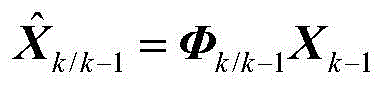
wherein: xk-1-state vector at time k-1; phik/k-1-a state transition matrix; prediction of the moment state vector.
Further, the state prediction of the unmanned aerial vehicle attitude quaternion comprises:

wherein: predicting the attitude quaternion of the unmanned aerial vehicle at the moment; q. q.sk-1Unmanned aerial vehicle attitude quaternion at the moment k-1; changing quantity of quaternion of unmanned aerial vehicle attitude from delta q-k-1 to k;
 -quaternion multiplication;
the calculation formula of the attitude quaternion variation of the unmanned aerial vehicle from the moment k-1 to the moment k is as follows:
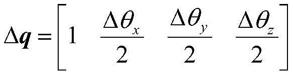
wherein: delta thetaxThe x-axis angle increment of the unmanned aerial vehicle from k-1 to k; delta thetayThe y-axis angle increment of the unmanned aerial vehicle from k-1 to k; delta thetazThe angular increment of the z axis of the unmanned aerial vehicle from the moment k-1 to the moment k; the increment calculation formula of each shaft angle of the unmanned aerial vehicle from the moment k-1 to the moment k is as follows:
Δθx=(ωx-εx)·Δt
Δθy=(ωy-εy)·Δt
Δθz=(ωz-εz)·Δt
wherein: omegax-angular velocity of the drone x-axis gyro output; epsilonx-zero offset of x-axis gyro of unmanned aerial vehicle; omegay-nobodyAngular velocity of the machine y-axis gyroscope output; epsilony-zero offset of the y-axis gyro of the drone; omegaz-angular velocity of the drone z-axis gyro output; epsilonz-zero offset of the unmanned aerial vehicle z-axis gyro; time interval Δ t-k-1 to k.
Further, unmanned aerial vehicle speed prediction:

wherein: predicting the speed of the unmanned aerial vehicle at the k moment; v. ofk-1-unmanned aerial vehicle speed at time k-1; g0-local gravitational acceleration of the unmanned aerial vehicle flight site;
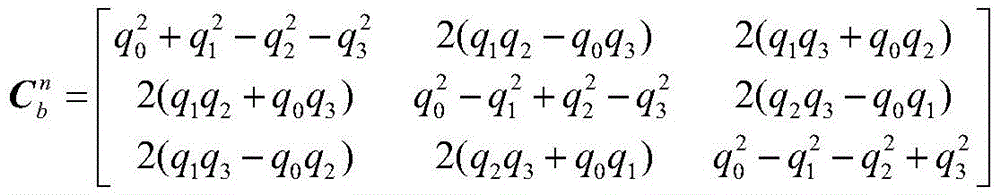
 -a coordinate transformation matrix from the carrier coordinate system to the navigation coordinate system; delta v-k-1 to k time velocity increment;
the calculation formula of the coordinate transformation matrix from the carrier coordinate system to the navigation coordinate system is as follows:

the calculation formula of the velocity increment from the moment k-1 to the moment k is as follows:
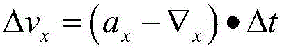

wherein: a isx-acceleration output by an x-axis accelerometer of the drone; -zero offset of the x-axis accelerometer of the drone; a isy-acceleration output by a y-axis accelerometer of the drone;
 -zero offset of the y-axis accelerometer of the drone; a isz-acceleration output by a z-axis accelerometer of the drone;
 -zero offset of the unmanned aerial vehicle z-axis accelerometer.
Further, the position prediction of the drone:
wherein: -unmanned aerial vehicle position prediction at time k; p is a radical ofk-1-drone position at time k-1; v. ofk-1-unmanned aerial vehicle speed at time k-1;
predicting zero offset of a gyro and zero offset of an accelerometer of the unmanned aerial vehicle:


wherein: -zero-offset of the unmanned aerial vehicle gyro at time k; epsilonk-1-zero-offset of the unmanned aerial vehicle gyro at time k-1;
 -zero offset of the unmanned aerial vehicle accelerometer at time k;
 and the unmanned aerial vehicle accelerometer has zero offset at the moment k-1.
Further, in step 1, the state transition matrix Φk/k-1The calculation of (2):
let k the state vector of the UAV be The state vector of the unmanned plane at the moment k-1 is
 Calculating a state vector at the moment k and a state vector Jacobian matrix at the moment k-1, wherein the state vector at the moment k and the state vector at the moment k-1 are calculated by calling a jacobian function in MATLAB, and the calculated matrix is a state transition matrix phi from the moment k-1 to the moment kk/k-1。
Further, in step 3, the measurement matrix is calculated:
first, the calculation of the attitude measurement matrix is introduced
Suppose a system can provide the attitude angle [ gamma theta phi ] of the unmanned aerial vehicle]TThe method comprises the following steps that gamma is an unmanned plane rolling angle, theta is an unmanned plane pitch angle, psi is an unmanned plane course angle, and the predicted value of the unmanned plane attitude angle is as follows:


wherein: -unmanned aerial vehicle roll angle measurement prediction value;
 -unmanned aerial vehicle pitch angle measurement prediction value;
 -unmanned aerial vehicle course angle measurement prediction value; q. q.s0—
 The real part of (1); [ q ] of1 q2 q3]—
 An imaginary part of;
calculating a Jacobian matrix of the attitude measurement predicted value and the state vector to obtain an attitude measurement matrix Hatt;
Calculation of a measurement matrix of speed and position:
suppose a system can provide the velocity v of the dronen ve vd]TAnd position [ p ]n pe pd]TThe speed and position predicted values of the unmanned aerial vehicle are as follows:


wherein: -unmanned aerial vehicle speed measurement prediction value;
 -a predicted value of the speed state of the drone;
 -unmanned aerial vehicle position measurement prediction value;
 -a predicted value of a position state of the drone;
respectively calculating the Jacobian matrix of the speed measurement predicted value, the position measurement predicted value and the state vector to obtain a speed measurement matrix HvMeasurement matrix H with positionp。
Further, the EKF filtering implementation is as follows:
state prediction

State error covariance matrix prediction

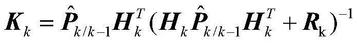
Filter gain

State error covariance matrix update

Status update

Wherein:
Pk-1EKF filtering at-k-1 time instantA state error covariance matrix; an EKF filtering state error covariance matrix prediction value at the k moment; qk-1-a system noise matrix at time k-1; rkMeasuring a noise matrix at the k moment; kk-a filter gain matrix at time k; pkEKF filter state error covariance matrix at time-k.
Further, the measurement is performed with consistency detection:
suppose the north velocity measurement is vnThe predicted value of the north-direction velocity measurement is The difference between the north-direction speed measurement value and the north-direction speed measurement prediction value is recorded as
 Hypothesis measurement noise matrix RkThe corresponding north velocity measurement noise is
 Error covariance matrix
 The corresponding north velocity error in is
 The measurement consistency detection formula is as follows:

where k is a coefficient, consider the measured noise array RkAnd error covariance matrix Is calculated at 1 sigma, and
 and
and all are the squares of the errors, if the consistency detection is required to pass under 3 sigma, k is generally 9, and the specific value can be set according to the sensor providing the measurement data;
consistency detection of other measurements is the same as consistency detection of the northbound speed, consistency detection is carried out on each measurement during EKF filtering, positive qualitative detection of a filter covariance matrix is carried out after the consistency detection is passed, if the measurement does not pass the consistency detection, only state prediction and state error covariance matrix prediction are carried out, and the positive qualitative detection of the filter covariance matrix is not carried out.
Further, the filter covariance matrix positive qualitative detection:
is provided with When updating the covariance matrix of the filter, P needs to be ensuredkFor positive definite matrix, the formula of step 4 of EKF filtering can be used to ensure the requirement
 Each diagonal element of (a) is greater than the corresponding diagonal element of KHP, and the filter covariance matrix positive qualitative detection formula is as follows:

when EKF filtering is carried out, only if the measurement passes consistency detection, the filter covariance matrix can be corrected by the measurement through positive qualitative detection, if only one detection fails, the measurement cannot be used for correcting the filter state, and only state prediction and state error covariance matrix prediction are carried out.
Compared with the prior art, the invention has the following technical effects:
the invention provides an EKF-based unmanned aerial vehicle integrated navigation method, and an integrated navigation system designed by the method can output high-precision unmanned aerial vehicle attitude, speed and position information in real time; the method can directly generate codes for programmable utilization through MATLAB, reduce complex formula derivation processes and improve the running efficiency of the CPU by 60 percent; the method can carry out consistency detection on the measurement information in real time, and prevents the adverse effect of the measurement information with larger error on the filter; the method can carry out positive qualitative detection on the covariance matrix of the filter in real time, prevent the filter from diverging and adjust the filter in time.
The problems of large calculated amount, poor robustness and complex and fussy model establishing process in the prior art are solved.
The invention has small calculation amount and high real-time performance.
The invention can directly output the attitude, the speed and the position of the unmanned aerial vehicle without establishing a complex error model.
The invention has simple design process, and the model establishment and the code generation are all automatically completed by MATLAB.
The invention can carry out consistency detection on the measurement information in real time and prevent the filter from being influenced by measurement with larger error.
The invention can carry out positive qualitative detection on the covariance matrix of the filter in real time, prevent the divergence of the filter and adjust the filter in time.
Drawings
FIG. 1 is a functional block diagram of an EKF-based integrated navigation method for an unmanned aerial vehicle;
fig. 2 is a block diagram of a sequential filtering process.
Detailed Description
The invention is further described below with reference to the accompanying drawings:
the invention provides an EKF-based unmanned aerial vehicle integrated navigation method, which comprises the following specific implementation modes:
the first step is to select the state vector (X) of the integrated navigation systemk) Constructing a prediction equation of the state vector, calculating the state prediction in MATLABThe Jacobian matrix of (phi) is a state transition matrixk/k-1) At this point, the prediction process for the state vector is complete.
Second step calculates state vector error covariance matrix prediction based on EKF filtering process And a filter gain matrix (K)k)。
Thirdly, selecting measurement according to the sensor in the integrated navigation system and calculating the predicted value of the measurement Then calculating the Jacobian matrix of the measured predicted value, which is the measuring matrix (H)k) And completing the model building of the integrated navigation system.
And fourthly, storing the expression of each matrix into a file in a character string mode, and finishing the operation of the programmable utilization code of the integrated navigation system, wherein the code can be directly used in a program.
And fifthly, adding measurement consistency check and covariance matrix positive qualitative detection when the filter is used, and finishing the design of the EKF-based integrated navigation system.
The principle of the unmanned aerial vehicle integrated navigation method based on the EKF provided by the invention is explained in detail below with reference to the accompanying drawings.
Selecting the attitude quaternion, the speed, the position, the gyro zero offset and the accelerometer zero offset of the unmanned aerial vehicle as state vectors, namely: wherein is q0Is the real part of the quaternion of the unmanned aerial vehicle attitude, q1、q2、q3For unmanned aerial vehicle attitude quaternion imaginary part, vnFor the north speed, v, of the unmanned planeeFor unmanned east speed, vdFor ground speed of unmanned aerial vehicle, pnFor north position of unmanned aerial vehicle, peFor the east position of the drone, pdFor ground-oriented position, ε, of the dronexZero-offset, epsilon, of the x-axis gyroyZero-offset, epsilon, of y-axis gyrozIs zero offset for the z-axis gyro,
 for the x-axis accelerometer zero-offset,
 for the zero offset of the accelerometer in the y-axis,
 zero offset for the z-axis accelerometer. The state equation of the system is

Wherein: xk-1-a state vector at time k-1; phik/k-1-a state transition matrix; -prediction of the state vector at time k;
the prediction of the state vector and phi are described belowk/k-1The calculation process of (2):
firstly, state prediction of unmanned aerial vehicle attitude quaternion is introduced

Wherein: predicting the unmanned aerial vehicle attitude quaternion at the moment k; q. q.sk-1-k-1 moment unmanned aerial vehicle attitude quaternion; delta q is the change of the quaternion of the unmanned aerial vehicle attitude from k-1 to k;
 -quaternion multiplication;
the calculation formula of the attitude quaternion variation of the unmanned aerial vehicle from the moment k-1 to the moment k is as follows:

wherein: delta thetax-unmanned aerial vehicle x axis angular increment from time k-1 to time k; delta thetayThe y-axis angle increment of the unmanned aerial vehicle from the moment k-1 to the moment k; delta thetaz-unmanned aerial vehicle z axis angular increment from time k-1 to time k;
the increment calculation formula of each shaft angle of the unmanned aerial vehicle from the moment k-1 to the moment k is as follows:
Δθx=(ωx-εx)·Δt
Δθy=(ωy-εy)·Δt
Δθz=(ωz-εz)·Δt
wherein: omegax-angular velocity of the drone x-axis gyro output; epsilonx-unmanned aerial vehicle x-axis gyro zero bias; omegay-angular velocity of the drone y-axis gyroscope output; epsilony-zero-offset of the unmanned aerial vehicle y-axis gyroscope; omegaz-angular velocity of the drone z-axis gyroscope output; epsilonz-zero-offset of the unmanned aerial vehicle z-axis gyro; Δ t-time interval k-1 to k;
so far, the prediction of the attitude quaternion of the unmanned aerial vehicle is completed, and the prediction of the speed of the unmanned aerial vehicle is introduced in the following

Wherein: -unmanned aerial vehicle speed prediction at time k; v. ofk-1-unmanned plane k-1 moment speed; g0-local gravitational acceleration of the unmanned aerial vehicle flight location;
 -a coordinate transformation matrix from the carrier coordinate system to the navigation coordinate system; Δ v-k-1 to kEngraving speed increment;
the calculation formula of the coordinate transformation matrix from the carrier coordinate system to the navigation coordinate system is as follows:
the calculation formula of the velocity increment from the moment k-1 to the moment k is as follows:


wherein: a isx-acceleration output by an unmanned aerial vehicle x-axis accelerometer; -zero offset of the unmanned aerial vehicle x-axis accelerometer; a isy-acceleration output by the drone y-axis accelerometer;
 -zero offset of the unmanned aerial vehicle y-axis accelerometer; a isz-acceleration output by a drone z-axis accelerometer;
 -zero offset of the unmanned aerial vehicle z-axis accelerometer;
to this end, the speed prediction of the drone is completed, and the location prediction of the drone is described below

Wherein: -unmanned aerial vehicle position prediction at time k; p is a radical ofk-1-drone position at time k-1; v. ofk-1-unmanned aerial vehicle speed at time k-1;
so far, the prediction of the position of the unmanned aerial vehicle is completed, and the prediction of the zero offset of the gyroscope and the zero offset of the accelerometer of the unmanned aerial vehicle is introduced below

Wherein: -zero-offset of the unmanned aerial vehicle gyro at time k; epsilonk-1-zero-offset of the unmanned aerial vehicle gyro at time k-1;
 -zero offset of the unmanned aerial vehicle accelerometer at time k;
 -zero offset of the unmanned aerial vehicle accelerometer at time k-1;
to this point, the prediction of the state vector of the drone is completed, and the state transition matrix Φ is introduced belowk/k-1The state vector of the unmanned aerial vehicle at the moment k is set as The state vector of the unmanned plane at the moment k-1 is
 The formula for predicting the state vector from time k-1 to time k has been described above, and thus onlyCalculating a state vector at the moment k and a state vector Jacobian matrix at the moment k-1 (the matrix can be calculated by calling a jacobian function in MATLAB), namely a state transition matrix phi from the moment k-1 to the moment kk/k-1The prediction process of the state vector and the state transition matrix phi have been completed to this pointk/k-1And (4) calculating. The calculation of the measurement matrix is described below, first, the calculation of the attitude measurement matrix is described
Suppose a system can provide the attitude angle [ gamma theta phi ] of the unmanned aerial vehicle]TThe method comprises the following steps that gamma is an unmanned plane rolling angle, theta is an unmanned plane pitch angle, psi is an unmanned plane course angle, and the predicted value of the unmanned plane attitude angle is as follows:


wherein: -unmanned aerial vehicle roll angle measurement prediction value;
 -unmanned aerial vehicle pitch angle measurement prediction value;

the attitude measurement matrix H can be calculated only by calculating the Jacobian matrix of the attitude measurement predicted value and the state vectoratt. The calculation of the attitude measurement matrix is completed, and the calculation of the measurement matrix of velocity and position is described below.
Suppose a system can provide the velocity v of the dronen ve vd]TAnd position [ p ]n pe pd]TThe speed and position predicted values of the unmanned aerial vehicle are as follows:


wherein: -unmanned aerial vehicle speed measurement prediction value;
 -a predicted value of the speed state of the drone;
 -unmanned aerial vehicle position measurement prediction value;
 -a prediction value of the position state of the drone;
the velocity measurement matrix H can be calculated only by respectively calculating the velocity measurement predicted value, the position measurement predicted value and the Jacobian matrix of the state vectorvMeasurement matrix H with positionp. The calculation of the speed measurement matrix and the position measurement matrix is completed, and the following calculation only needs to be carried out according to an EKF filtering equationCalculating an expression of the error covariance matrix and the gain matrix and storing the expression in a file, wherein the implementation process of the EKF filtering is as follows:
state prediction
State error covariance matrix prediction

Filter gain

State error covariance matrix update

Status update

Wherein: pk-1-EKF filter state error covariance matrix at time k-1; -EKF filter state error covariance matrix prediction at time k; qk-1-the system noise matrix at time k-1; rkMeasuring the noise matrix at time k; kk-a filter gain matrix at time k; pk-EKF filter state error covariance matrix at time k;
in order to increase the robustness of the system and avoid the adverse effect of the measurement with a large error on the filter, consistency detection needs to be performed on the measurement in real time, and in order to perform consistency detection on each measurement separately, the EKF filtering form needs to be designed as a sequential filtering form, an implementation flow chart of the sequential filtering is shown in fig. 2, and a method for performing consistency detection on the measurement is described below.
Suppose the north velocity measurement is vnThe predicted value of the north-direction velocity measurement is The difference between the north-direction speed measurement value and the north-direction speed measurement prediction value is recorded as
 Hypothesis measurement noise matrix (R)k) The corresponding north velocity measurement noise is
 Error covariance matrix
 The corresponding north velocity error in is
 The measurement consistency detection formula is as follows:

where k is a coefficient, generally referred to as a measured noise matrix (R)k) And error covariance matrix Is calculated at 1 sigma, and
 and
and are all the squares of the errors, and the error rate,if the consistency check is to be passed at 3 σ, k is typically 9, and the specific value can be set according to the sensor providing the metrology data.
Consistency detection of other measurements is the same as consistency detection of a northbound speed, consistency detection is carried out on each measurement when EKF filtering is carried out, filter covariance matrix positive qualitative detection is carried out after the consistency detection is passed, namely step 4 of the EKF, if the measurement does not pass the consistency detection, only state prediction and state error covariance matrix prediction are carried out, filter covariance matrix positive qualitative detection is not carried out, namely step 1 and step 2 of the EKF filtering, in order to reduce the calculation amount of a CPU, the consistency detection step is generally carried out between step 2 and step 3 of the EKF filtering, if the consistency detection does not pass, filter gain does not need to be calculated, and the calculation amount of the CPU can be greatly reduced.
Until the consistency test is completed, the positive qualitative test of the covariance matrix of the filter is introduced below When updating the covariance matrix of the filter, namely step 4 of EKF filtering, P needs to be ensuredkFor positive definite matrix, the formula of step 4 of EKF filtering can be used to ensure the requirement
 Each diagonal element of (a) is greater than the corresponding diagonal element of KHP, the filter covariance matrix positive qualitative detection formula is as follows:

when EKF filtering is carried out, only if the measurement passes consistency detection, the filter covariance matrix can utilize the measurement to correct the state of the filter through positive qualitative detection, if only one detection fails, the measurement cannot be utilized to correct the state of the filter, and only state prediction and state error covariance matrix prediction are carried out, namely, the 1 st step and the 2 nd step of EKF filtering.
Claims (8)
1. An EKF-based unmanned aerial vehicle integrated navigation method is characterized by comprising the following steps:
step 1, selecting a state vector X of the integrated navigation systemkConstructing a prediction equation of the state vector, and calculating a Jacobian matrix of the state prediction, wherein the Jacobian matrix is a state transition matrix phik/k-1;
Step 2, calculating the state vector error covariance matrix prediction according to the EKF filtering process And a filter gain matrix Kk;
Step 3, selecting measurement according to the sensor in the integrated navigation system and calculating the predicted value of the measurement Then calculating the Jacobian matrix of the measurement prediction value, wherein the Jacobian matrix is the measurement matrix HkCompleting the model establishment of the integrated navigation system;
step 4, storing the expression of each matrix to a file according to a character string form, so as to finish the programmable utilization code of the integrated navigation system;
step 5, adding measurement consistency check and covariance matrix positive qualitative detection when the filter is used;
in step 3, calculating a measurement matrix:
first, the calculation of the attitude measurement matrix is introduced
Suppose a system can provide the attitude angle [ gamma theta phi ] of the unmanned aerial vehicle]TThe method comprises the following steps that gamma is an unmanned plane rolling angle, theta is an unmanned plane pitch angle, psi is an unmanned plane course angle, and the predicted value of the unmanned plane attitude angle is as follows:


wherein: -unmanned aerial vehicle roll angle measurement prediction value;
 -unmanned aerial vehicle pitch angle measurement prediction value;
 -unmanned aerial vehicle course angle measurement prediction value;
 the real part of (1);
 an imaginary part of;
calculating a Jacobian matrix of the attitude measurement predicted value and the state vector to obtain an attitude measurement matrix Hatt;
Calculation of a measurement matrix of speed and position:
suppose a system can provide the velocity v of the dronen ve vd]TAnd position [ p ]n pe pd]TThe speed and position predicted values of the unmanned aerial vehicle are as follows:
wherein: -unmanned aerial vehicle speed measurement prediction value;
 -a predicted value of the speed state of the drone;
 -unmanned aerial vehicle position measurement prediction value;
 -a predicted value of a position state of the drone;
respectively calculating the Jacobian matrix of the speed measurement predicted value, the position measurement predicted value and the state vector to obtain a speed measurement matrix HvMeasurement matrix H with positionp;
Measuring and carrying out consistency detection:
suppose the north velocity measurement is vnThe predicted value of the north-direction velocity measurement is The difference between the north-direction speed measurement value and the north-direction speed measurement prediction value is recorded as
 Hypothesis measurement noise matrix RkThe corresponding north velocity measurement noise is
 Error covariance matrix
 The corresponding north velocity error in is
 The measurement consistency detection formula is as follows:
where k is a coefficient, consider the measured noise array RkAnd error covariance matrix Is calculated at 1 sigma, and
 and
and all are the squares of the errors, if the consistency detection is required to pass under 3 sigma, k is generally 9, and the specific value can be set according to the sensor providing the measurement data;
consistency detection of other measurements is the same as consistency detection of the northbound speed, consistency detection is carried out on each measurement during EKF filtering, positive qualitative detection of a filter covariance matrix is carried out after the consistency detection is passed, if the measurement does not pass the consistency detection, only state prediction and state error covariance matrix prediction are carried out, and the positive qualitative detection of the filter covariance matrix is not carried out.
2. The EKF-based unmanned aerial vehicle integrated navigation method as claimed in claim 1, wherein the step 1 specifically comprises: selecting the attitude quaternion, the speed, the position, the gyro zero offset and the accelerometer zero offset of the unmanned aerial vehicle as state vectors, namely: wherein is q0Is the real part of the quaternion of the unmanned aerial vehicle attitude, q1、q2、q3For unmanned aerial vehicle attitude quaternion imaginary part, vnFor the north speed, v, of the unmanned planeeFor unmanned east speed, vdFor ground speed of unmanned aerial vehicle, pnFor north position of unmanned aerial vehicle, peFor the east position of the drone, pdFor ground-oriented position, ε, of the dronexZero-offset, epsilon, of the x-axis gyroyZero-offset, epsilon, of y-axis gyrozIs zero offset for the z-axis gyro,
 for the x-axis accelerometer zero-offset,
 for the zero offset of the accelerometer in the y-axis,
 zero offset for the z-axis accelerometer;
the state equation of the system is as follows:
wherein: xk-1-state vector at time k-1; phik/k-1-a state transition matrix; prediction of the moment state vector.
3. The EKF-based unmanned aerial vehicle integrated navigation method of claim 2, wherein the state prediction of the unmanned aerial vehicle attitude quaternion comprises:
wherein: predicting the attitude quaternion of the unmanned aerial vehicle at the moment; q. q.sk-1Unmanned aerial vehicle attitude quaternion at the moment k-1; changing quantity of quaternion of unmanned aerial vehicle attitude from delta q-k-1 to k;
 -quaternion multiplication;
the calculation formula of the attitude quaternion variation of the unmanned aerial vehicle from the moment k-1 to the moment k is as follows:
wherein: delta thetaxThe x-axis angle increment of the unmanned aerial vehicle from k-1 to k; delta thetayThe y-axis angle increment of the unmanned aerial vehicle from k-1 to k; delta thetazThe angular increment of the z axis of the unmanned aerial vehicle from the moment k-1 to the moment k; the increment calculation formula of each shaft angle of the unmanned aerial vehicle from the moment k-1 to the moment k is as follows:
Δθx=(ωx-εx)·Δt
Δθy=(ωy-εy)·Δt
Δθz=(ωz-εz)·Δt
wherein: omegax-angular velocity of the drone x-axis gyro output; epsilonx-zero offset of x-axis gyro of unmanned aerial vehicle; omegay-angular velocity of the drone y-axis gyroscope output; epsilony-zero offset of the y-axis gyro of the drone; omegaz-angular velocity of the drone z-axis gyro output; epsilonz-zero offset of the unmanned aerial vehicle z-axis gyro; time interval Δ t-k-1 to k.
4. The EKF-based unmanned aerial vehicle integrated navigation method of claim 2, wherein the speed prediction of the unmanned aerial vehicle is as follows:

wherein: predicting the speed of the unmanned aerial vehicle at the k moment; v. ofk-1-unmanned aerial vehicle speed at time k-1; g0-local gravitational acceleration of the unmanned aerial vehicle flight site;
 -a coordinate transformation matrix from the carrier coordinate system to the navigation coordinate system; delta v-k-1 to k time velocity increment;
the calculation formula of the coordinate transformation matrix from the carrier coordinate system to the navigation coordinate system is as follows:

the calculation formula of the velocity increment from the moment k-1 to the moment k is as follows:


wherein: a isx-acceleration output by an x-axis accelerometer of the drone; -zero offset of the x-axis accelerometer of the drone; a isy-acceleration output by a y-axis accelerometer of the drone;
 -zero offset of the y-axis accelerometer of the drone; a isz-acceleration output by a z-axis accelerometer of the drone;
 -zero offset of the unmanned aerial vehicle z-axis accelerometer.
5. The EKF-based unmanned aerial vehicle integrated navigation method of claim 2, wherein the position prediction of the unmanned aerial vehicle comprises:

wherein: -unmanned aerial vehicle position prediction at time k; p is a radical ofk-1-drone position at time k-1; v. ofk-1-unmanned aerial vehicle speed at time k-1;
predicting zero offset of a gyro and zero offset of an accelerometer of the unmanned aerial vehicle:

wherein: -zero-offset of the unmanned aerial vehicle gyro at time k; epsilonk-1-zero-offset of the unmanned aerial vehicle gyro at time k-1;
 -zero offset of the unmanned aerial vehicle accelerometer at time k;
 time unmanned aerial vehicleThe accelerometer has zero offset.
6. The EKF-based unmanned aerial vehicle integrated navigation method of claim 1, wherein in step 1, the state transition matrix Φk/k-1The calculation of (2):
let k the state vector of the UAV be The state vector of the unmanned plane at the moment k-1 is
 Calculating a state vector at the moment k and a state vector Jacobian matrix at the moment k-1, wherein the state vector at the moment k and the state vector at the moment k-1 are calculated by calling a jacobian function in MATLAB, and the calculated matrix is a state transition matrix phi from the moment k-1 to the moment kk/k-1。
7. The EKF-based unmanned aerial vehicle integrated navigation method of claim 1, wherein EKF filtering is implemented as follows:
state prediction

State error covariance matrix prediction

Filter gain
State error covariance matrix update

Status update

Wherein:
Pk-1an EKF filtering state error covariance matrix at the k-1 moment; predicting a covariance matrix of the EKF filtering state errors at the moment; qk-1-a system noise matrix at time k-1; rkMeasuring a noise matrix at the k moment; kk-a filter gain matrix at time k; pkEKF filter state error covariance matrix at time-k.
8. The EKF-based unmanned aerial vehicle integrated navigation method of claim 1, wherein the filter covariance matrix positive qualitative detection:
is provided with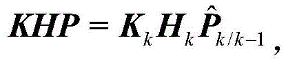 When updating the covariance matrix of the filter, P needs to be ensuredkFor positive definite matrix, the formula of step 4 of EKF filtering can be used to ensure the requirement
 Each diagonal element of (a) is greater than the corresponding diagonal element of KHP, and the filter covariance matrix positive qualitative detection formula is as follows:
when EKF filtering is carried out, only if the measurement passes consistency detection, the filter covariance matrix can be corrected by the measurement through positive qualitative detection, if only one detection fails, the measurement cannot be used for correcting the filter state, and only state prediction and state error covariance matrix prediction are carried out.
Priority Applications (1)
| Application Number | Priority Date | Filing Date | Title |
|---|---|---|---|
| CN202010048409.6A CN111207734B (en) | 2020-01-16 | 2020-01-16 | EKF-based unmanned aerial vehicle integrated navigation method |
Applications Claiming Priority (1)
| Application Number | Priority Date | Filing Date | Title |
|---|---|---|---|
| CN202010048409.6A CN111207734B (en) | 2020-01-16 | 2020-01-16 | EKF-based unmanned aerial vehicle integrated navigation method |
Publications (2)
| Publication Number | Publication Date |
|---|---|
| CN111207734A CN111207734A (en) | 2020-05-29 |
| CN111207734B true CN111207734B (en) | 2022-01-07 |
Family
ID=70785457
Family Applications (1)
| Application Number | Title | Priority Date | Filing Date |
|---|---|---|---|
| CN202010048409.6A Active CN111207734B (en) | 2020-01-16 | 2020-01-16 | EKF-based unmanned aerial vehicle integrated navigation method |
Country Status (1)
| Country | Link |
|---|---|
| CN (1) | CN111207734B (en) |
Families Citing this family (6)
| Publication number | Priority date | Publication date | Assignee | Title |
|---|---|---|---|---|
| CN112629521A (en) * | 2020-12-13 | 2021-04-09 | 西北工业大学 | Modeling method for dual-redundancy combined navigation system of rotor aircraft |
| CN113514052A (en) * | 2021-06-10 | 2021-10-19 | 西安因诺航空科技有限公司 | Multi-machine cooperation high-precision active target positioning method and system |
| CN116753953A (en) * | 2023-05-25 | 2023-09-15 | 扎鲁特旗扎哈淖尔煤业有限公司 | A vision-based UAV integrated navigation method |
| CN116907501B (en) * | 2023-06-30 | 2024-11-29 | 哈尔滨工业大学(威海) | A UAV swarm collaborative positioning method and system based on hierarchical extended Kalman filter |
| CN116907500A (en) * | 2023-06-30 | 2023-10-20 | 哈尔滨工业大学(威海) | Confidence factor-based self-unmanned aerial vehicle optimized distributed EKF co-location method and system |
| CN117191022A (en) * | 2023-08-24 | 2023-12-08 | 西安因诺航空科技有限公司 | A multi-visual tag positioning method for drones based on EKF |
Citations (18)
| Publication number | Priority date | Publication date | Assignee | Title |
|---|---|---|---|---|
| CN103414451A (en) * | 2013-07-22 | 2013-11-27 | 北京理工大学 | Extension Kalman filtering method applied to flight vehicle attitude estimation |
| CN104215262A (en) * | 2014-08-29 | 2014-12-17 | 南京航空航天大学 | An Online Dynamic Identification Method for Inertial Sensor Errors in Inertial Navigation System |
| CN104252178A (en) * | 2014-09-12 | 2014-12-31 | 西安电子科技大学 | A Target Tracking Method Based on Strong Maneuvering |
| CN104462824A (en) * | 2014-12-12 | 2015-03-25 | 广西科技大学 | Single-cell EKF (extended Kalman filter) and UKF (unscented Kalman filter) estimation comparing method |
| CN105203098A (en) * | 2015-10-13 | 2015-12-30 | 上海华测导航技术股份有限公司 | Whole attitude angle updating method applied to agricultural machinery and based on nine-axis MEMS (micro-electromechanical system) sensor |
| CN105259902A (en) * | 2015-09-06 | 2016-01-20 | 江苏科技大学 | Inertial navigation method and system of underwater robot |
| CN105352529A (en) * | 2015-11-16 | 2016-02-24 | 南京航空航天大学 | Multisource-integrated-navigation-system distributed inertia node total-error on-line calibration method |
| CN108226980A (en) * | 2017-12-23 | 2018-06-29 | 北京卫星信息工程研究所 | Difference GNSS and the adaptive close coupling air navigation aids of INS based on Inertial Measurement Unit |
| CN108536163A (en) * | 2018-03-15 | 2018-09-14 | 南京航空航天大学 | A kind of kinetic model/laser radar Combinated navigation method under single-sided structure environment |
| CN109030867A (en) * | 2017-06-08 | 2018-12-18 | 海智芯株式会社 | The method and apparatus for calculating angular speed using acceleration transducer and geomagnetic sensor |
| CN109506646A (en) * | 2018-11-20 | 2019-03-22 | 石家庄铁道大学 | A kind of the UAV Attitude calculation method and system of dual controller |
| CN109540126A (en) * | 2018-12-03 | 2019-03-29 | 哈尔滨工业大学 | A kind of inertia visual combination air navigation aid based on optical flow method |
| CN109931926A (en) * | 2019-04-04 | 2019-06-25 | 山东智翼航空科技有限公司 | Unmanned aerial vehicle seamless autonomous navigation algorithm based on station center coordinate system |
| CN110146077A (en) * | 2019-06-21 | 2019-08-20 | 台州知通科技有限公司 | Calculation Method of Attitude Angle of Mobile Robot |
| CN110231029A (en) * | 2019-05-08 | 2019-09-13 | 西安交通大学 | A kind of underwater robot Multi-sensor Fusion data processing method |
| CN110440797A (en) * | 2019-08-28 | 2019-11-12 | 广州小鹏汽车科技有限公司 | Vehicle attitude estimation method and system |
| CN110487271A (en) * | 2019-09-26 | 2019-11-22 | 哈尔滨工程大学 | Elman neural network aiding tight integration air navigation aid when a kind of GNSS signal is obstructed |
| CN110598370A (en) * | 2019-10-18 | 2019-12-20 | 太原理工大学 | Robust Attitude Estimation for Multi-rotor UAV Based on Fusion of SIP and EKF |
-
2020
- 2020-01-16 CN CN202010048409.6A patent/CN111207734B/en active Active
Patent Citations (18)
| Publication number | Priority date | Publication date | Assignee | Title |
|---|---|---|---|---|
| CN103414451A (en) * | 2013-07-22 | 2013-11-27 | 北京理工大学 | Extension Kalman filtering method applied to flight vehicle attitude estimation |
| CN104215262A (en) * | 2014-08-29 | 2014-12-17 | 南京航空航天大学 | An Online Dynamic Identification Method for Inertial Sensor Errors in Inertial Navigation System |
| CN104252178A (en) * | 2014-09-12 | 2014-12-31 | 西安电子科技大学 | A Target Tracking Method Based on Strong Maneuvering |
| CN104462824A (en) * | 2014-12-12 | 2015-03-25 | 广西科技大学 | Single-cell EKF (extended Kalman filter) and UKF (unscented Kalman filter) estimation comparing method |
| CN105259902A (en) * | 2015-09-06 | 2016-01-20 | 江苏科技大学 | Inertial navigation method and system of underwater robot |
| CN105203098A (en) * | 2015-10-13 | 2015-12-30 | 上海华测导航技术股份有限公司 | Whole attitude angle updating method applied to agricultural machinery and based on nine-axis MEMS (micro-electromechanical system) sensor |
| CN105352529A (en) * | 2015-11-16 | 2016-02-24 | 南京航空航天大学 | Multisource-integrated-navigation-system distributed inertia node total-error on-line calibration method |
| CN109030867A (en) * | 2017-06-08 | 2018-12-18 | 海智芯株式会社 | The method and apparatus for calculating angular speed using acceleration transducer and geomagnetic sensor |
| CN108226980A (en) * | 2017-12-23 | 2018-06-29 | 北京卫星信息工程研究所 | Difference GNSS and the adaptive close coupling air navigation aids of INS based on Inertial Measurement Unit |
| CN108536163A (en) * | 2018-03-15 | 2018-09-14 | 南京航空航天大学 | A kind of kinetic model/laser radar Combinated navigation method under single-sided structure environment |
| CN109506646A (en) * | 2018-11-20 | 2019-03-22 | 石家庄铁道大学 | A kind of the UAV Attitude calculation method and system of dual controller |
| CN109540126A (en) * | 2018-12-03 | 2019-03-29 | 哈尔滨工业大学 | A kind of inertia visual combination air navigation aid based on optical flow method |
| CN109931926A (en) * | 2019-04-04 | 2019-06-25 | 山东智翼航空科技有限公司 | Unmanned aerial vehicle seamless autonomous navigation algorithm based on station center coordinate system |
| CN110231029A (en) * | 2019-05-08 | 2019-09-13 | 西安交通大学 | A kind of underwater robot Multi-sensor Fusion data processing method |
| CN110146077A (en) * | 2019-06-21 | 2019-08-20 | 台州知通科技有限公司 | Calculation Method of Attitude Angle of Mobile Robot |
| CN110440797A (en) * | 2019-08-28 | 2019-11-12 | 广州小鹏汽车科技有限公司 | Vehicle attitude estimation method and system |
| CN110487271A (en) * | 2019-09-26 | 2019-11-22 | 哈尔滨工程大学 | Elman neural network aiding tight integration air navigation aid when a kind of GNSS signal is obstructed |
| CN110598370A (en) * | 2019-10-18 | 2019-12-20 | 太原理工大学 | Robust Attitude Estimation for Multi-rotor UAV Based on Fusion of SIP and EKF |
Non-Patent Citations (2)
| Title |
|---|
| Consistency of the EKF-SLAM Algorithm;Tim Bailey等;《IEEE》;20061231;5-7 * |
| 两种联邦滤波系统级故障检测方案对比与仿真;彭立等;《电光与控制》;20090228;第16卷(第2期);76-80 * |
Also Published As
| Publication number | Publication date |
|---|---|
| CN111207734A (en) | 2020-05-29 |
Similar Documents
| Publication | Publication Date | Title |
|---|---|---|
| CN111207734B (en) | EKF-based unmanned aerial vehicle integrated navigation method | |
| CN112097763B (en) | Underwater vehicle combined navigation method based on MEMS IMU/magnetometer/DVL combination | |
| CN110274588B (en) | Multi-source fusion navigation method based on two-layer nested factor graph based on UAV swarm information | |
| CN108180925B (en) | Odometer-assisted vehicle-mounted dynamic alignment method | |
| CN104655152B (en) | A real-time delivery alignment method for airborne distributed POS based on federated filtering | |
| CN102519470B (en) | Multi-level embedded integrated navigation system and navigation method | |
| CN101949703B (en) | Strapdown inertial/satellite combined navigation filtering method | |
| CN110243377B (en) | Cluster aircraft collaborative navigation method based on hierarchical structure | |
| CN105737823B (en) | A kind of GPS/SINS/CNS Combinated navigation methods based on five rank CKF | |
| WO2024092876A1 (en) | High-precision underwater moving base alignment method and system based on magnetic compass and velocimeter | |
| CN110849360B (en) | Distributed relative navigation method for multi-machine collaborative formation flight | |
| CN105806363B (en) | The underwater large misalignment angle alignment methods of SINS/DVL based on SRQKF | |
| CN111323050A (en) | Strapdown inertial navigation and Doppler combined system calibration method | |
| CN110207691A (en) | A kind of more unmanned vehicle collaborative navigation methods based on data-link ranging | |
| CN110160554A (en) | A kind of single-shaft-rotation Strapdown Inertial Navigation System scaling method based on optimizing method | |
| CN113959462B (en) | Quaternion-based inertial navigation system self-alignment method | |
| CN111220151B (en) | Inertia and milemeter combined navigation method considering temperature model under load system | |
| CN109945895B (en) | Inertial navigation initial alignment method based on fading smooth variable structure filtering | |
| CN111121766A (en) | An Astronomical and Inertial Integrated Navigation Method Based on Starlight Vector | |
| CN113503894B (en) | Inertial navigation system error calibration method based on gyro reference coordinate system | |
| CN110926468A (en) | Communication-in-motion antenna multi-platform navigation attitude determination method based on transfer alignment | |
| CN110361031B (en) | A fast calibration method of IMU full parameter error based on backtracking theory | |
| CN111189442A (en) | Multi-source navigation information state prediction method of unmanned aerial vehicle based on CEPF | |
| CN103630146A (en) | Laser gyroscope IMU (inertial measurement unit) calibration method combining discrete analysis and Kalman filtration | |
| CN114061575B (en) | Method and system for precise alignment of missile attitude angle under large misalignment angle conditions |
Legal Events
| Date | Code | Title | Description |
|---|---|---|---|
| PB01 | Publication | ||
| PB01 | Publication | ||
| SE01 | Entry into force of request for substantive examination | ||
| SE01 | Entry into force of request for substantive examination | ||
| GR01 | Patent grant | ||
| GR01 | Patent grant |