This non-provisional application is based on Japanese patent application No.2018-218005 filed on 21.11.2018 to the office, the entire contents of which are incorporated herein by reference.
Disclosure of Invention
In contact charging (also commonly referred to as "cable charging"), timed charging is performed while a vehicle and a charging station (more specifically, a power supply device outside the vehicle) are connected to each other via a charging cable. The power supply from the power source of the charging station to the vehicle through the charging cable can be realized by connecting the connector of the charging cable coupled with the charging station to the inlet of the vehicle.
The user can remove the connector of the charging cable from the inlet of the vehicle during the timer charging (hereinafter also referred to as "removing the cable in the middle of charging"). However, the above-mentioned japanese patent laid-open No.2012-5227 does not anticipate removal of the cable in the middle of charging.
The processing to be executed by the vehicle control apparatus when the cable is removed in the middle of charging is considered to be forced termination of ongoing timed charging without waiting for the termination time (hereinafter also simply referred to as "termination"). However, if the timed charging is always terminated when the cable is removed in the middle of charging, convenience for the user may be impaired.
For example, in a narrow parking lot, the charging cable may obstruct pedestrian traffic during the timed charging. In this case, the user may wish to temporarily pull out the connector of the charging cable from the inlet of the vehicle, let a pedestrian pass, and immediately thereafter reconnect the connector to the inlet and charge the vehicle again. However, if the timer charging is terminated when the connector is pulled out from the inlet as described above, the user needs to set the charging schedule again to allow the timer charging after the connector is reconnected to the inlet. Such an operation is burdensome to the user and reduces the convenience of the user.
The present disclosure is made to solve the above-described problems, and an object of the present disclosure is to provide a vehicle control apparatus that achieves improved user convenience during timer charging.
The vehicle control device according to the present disclosure is configured to perform timed charging to supply power to the vehicle from a power supply device outside the vehicle through a charging cable. The timed charging is charging that starts charging a battery mounted in a vehicle upon reaching a start time and ends charging the battery upon reaching an end time. The vehicle control apparatus according to the present disclosure includes an execution unit and a recovery processing unit. The execution unit is configured to execute the timer charging using a preset start time and end time. The resume processing unit is configured to suspend the timed charging when the charging cable is disconnected from at least one of the vehicle and the power supply device during the timed charging, resume the suspended timed charging when a predetermined resume condition is satisfied, and end the suspended timed charging without waiting for an end time when the predetermined resume condition is not satisfied. The predetermined resume condition includes a condition that the charging cable is reconnected after the timed charging pause and before the end time.
The vehicle control apparatus suspends the timed charging when the charging cable is disconnected during the timed charging, and resumes the suspended timed charging without terminating the suspended timed charging when the resume condition is satisfied. As a result, by setting the resume condition in advance so as to satisfy the resume condition in the case where the resume of the suspended timer charging is requested, it is possible to achieve an improvement in user convenience in the timer charging.
More specifically, the recovery condition may be set to be satisfied when the charging cable is reconnected before the end time without the vehicle starting to travel since the charging cable has been disconnected and the timed charging has been suspended. "the vehicle starts running" means that the vehicle in a non-running state (for example, in a stopped state) becomes a continuous running state. In the case where the vehicle is running only temporarily in the garage to be parked, the vehicle is not regarded as having started running. When the charging cable is disconnected, the timed charging is suspended, and thereafter the vehicle travels a prescribed distance or more (i.e., the vehicle has started traveling), it can be concluded that the vehicle is not temporarily traveling. A user reconnecting the charging cable before the vehicle starts running will most likely want to resume the suspended timed charging. As a result, setting the recovery condition as described above can contribute to improvement of user convenience during the timer charging.
The resume condition may be set to be satisfied when the charging cable is reconnected before the end time in a case where a prescribed period of time has not elapsed since the charging cable has been disconnected and the timer charging has been suspended. When the user immediately reconnects the charging cable without having the charging cable disconnected for a period of time, the user is highly likely to wish to resume the suspended timed charging (i.e., the user is willing to continue the timed charging). As a result, the recovery condition set as described above can contribute to improvement of user convenience during the timer charging.
The recovery processing unit may be configured to determine that the predetermined recovery condition is not satisfied when it is sensed that the vehicle has started traveling in a period from disconnection from the charging cable and suspension of the timed charging to reconnection of the charging cable. For example, the resume processing unit may be configured to determine that the predetermined resume condition is not satisfied when the vehicle travels a prescribed distance or longer in a period from disconnection from the charging cable and timed charging suspension to reconnection of the charging cable.
According to the above configuration, when the vehicle starts running as described above, it is determined that the predetermined recovery condition is not satisfied, and the suspended timed charge ends without waiting until the end time. As a result, the control of the vehicle is smoothly transitioned from the charging control to the running control.
The vehicle control apparatus may further include a first changing unit configured to: when a predetermined recovery condition is satisfied, the end time of the recovered timed charge is changed so as to replenish at least a part of the amount of the electric power that is not charged. The uncharged power is power that is not charged at the time of the timer charge pause.
According to the above configuration, the amount of charge that is insufficient due to suspension can be replenished by the resumed timed charging. It should be noted that it is not always beneficial to the user to allow the user to change the end time because the charging schedule can be set according to a time period in which the electricity rate is cheap. Thus, the user can be allowed to select (i.e., set to the vehicle control apparatus) in advance one of a mode in which the change of the end time is allowed and a mode in which the change of the end time is not allowed. The first changing unit may be configured to change the end time of the timing charge to be resumed only if the change-allowed mode is selected when a predetermined resumption condition is satisfied.
The vehicle control apparatus may further include a second changing unit configured to: if a predetermined recovery condition is satisfied, the amount of charge per unit time of the recovered timed charge is changed so as to replenish at least a part of the amount of electric power that is not charged. The uncharged power is power that is not charged at the time of the timer charge pause.
According to the above configuration, the amount of charge insufficient due to suspension can be replenished by the resumed timed charging without changing the charging schedule set by the user.
The execution unit may be configured to set a start time and an end time for each of the plurality of timed charges. The plurality of timed charges may include a first timed charge and a second timed charge. The vehicle control apparatus may further include a third changing unit configured to: if a predetermined recovery condition is satisfied, at least one of the start time and the end time of the second timed charge is changed so as to replenish at least a part of the amount of the electric power of the uncharged power by the second timed charge. The uncharged power is power that is not charged at the time of the first timing charge pause.
According to the above configuration, the amount of charge that is insufficient due to the halfway end of the first timer charge can be made up by the second timer charge (e.g., the next timer charge). Further, in the above-described configuration, as described above, the user may be allowed to select in advance (i.e., setting of the vehicle control apparatus) one of the mode in which the change of the end time is allowed and the mode in which the change is not allowed. The third changing unit may be configured to change at least one of the start time and the end time of the second timed charge only if the change-permitted mode is selected when the predetermined recovery condition is satisfied.
The vehicle control apparatus may further include an end processing unit configured to notify or record that the timed charging has ended halfway, at least if a predetermined recovery condition is not satisfied.
The user can confirm from the notification or the record that the timer charging has ended halfway. As a result, according to the above configuration, the following can be prevented from occurring: the user drives the vehicle without knowing that the timed charging has ended halfway and that the electric power stored in the battery mounted in the vehicle is insufficient (and therefore the vehicle is out of power).
The foregoing and other objects, features, aspects and advantages of the present disclosure will become apparent from the following detailed description of the present disclosure when taken in conjunction with the accompanying drawings.
Detailed Description
Embodiments according to the present disclosure will be described with reference to the accompanying drawings. It should be noted that the same reference numerals are used to refer to the same or similar parts, and the description thereof will not be repeated. Hereinafter, the electronic control unit will be referred to as "ECU".
Fig. 1 is a block diagram of a charging system to which a vehicle control apparatus according to the present embodiment is applied. Referring to fig. 1, charging system 1 includes vehicle 100, charging station 200, and charging cable 300. The vehicle 100 includes a battery 130 for storing electric power for electric drive. The battery 130 includes a secondary battery such as a lithium ion battery or a nickel hydrogen battery. The secondary battery may be a single cell or a battery pack. Instead of the secondary battery, other electric storage devices such as an electric double layer capacitor may be employed. The vehicle 100 may be an electric vehicle capable of running using only the electric power stored in the battery 130 or a hybrid vehicle capable of running using both the electric power stored in the battery 130 and the output power of an engine (not shown). The battery 130 according to the present embodiment corresponds to one example of the "battery" according to the present disclosure.
Vehicle 100 is able to receive power supply from charging station 200 and perform contact charging on battery 130. Charging station 200 may be an AC (alternating current) charging station having an AC power scheme (e.g., a normal charger) or a DC (direct current) charging station having a DC power scheme (e.g., a quick charger). Vehicle 100 includes a charging inlet 110 and a charger 120 (vehicle charger) that support the power scheme of charging station 200. Although fig. 1 shows only the charging inlet 110 and the charger 120, the vehicle 100 may include a plurality of charging inlets and chargers for different power supply schemes in order to support a plurality of types of power supply schemes.
Charging cable 300 is connected to charging station 200. In the present embodiment, charging cable 300 is always connected to charging station 200. However, the present disclosure is not limited thereto. Charging cable 300 may be detachable from charging stand 200. The charging cable 300 has a charging connector 310 at the tip end, and the signal line and the power line are contained inside the charging cable 300. Charging connector 310 of charging cable 300 coupled to charging stand 200 is connected to charging inlet 110 of vehicle 100, so that power can be supplied from charging stand 200 to vehicle 100 through charging cable 300. The charger 120 included in the vehicle 100 includes a circuit (e.g., a power converter circuit and a filter circuit, not shown) for performing prescribed processing on the electric power input to the charging inlet 110. Such processing by the circuit allows the charger 120 to output power (DC power) suitable for charging the battery 130 to the battery 130. Charging station 200 according to the present embodiment corresponds to one example of "power supply apparatus outside a vehicle" according to the present disclosure.
In addition to the charging inlet 110, the charger 120, and the battery 130, the vehicle 100 further includes a travel driving unit 140, an ECU150, an input device 160, a notification device 170, a position detection unit 180, and driving wheels W. It should be noted that the drive system of the vehicle 100 is not limited to the front-wheel drive shown in fig. 1, but may be a front-engine rear-wheel drive or a four-wheel drive.
The travel drive unit 140 includes a Power Control Unit (PCU) and a Motor Generator (MG), both not shown. The travel drive unit 140 is configured to cause the vehicle 100 to travel using the electric power stored in the battery 130. The PCU includes, for example, a control apparatus including a processor, an inverter, and a converter (all not shown). The control apparatus included in the PCU is configured to receive an instruction (control signal) from the ECU150 and control the inverter and the converter included in the PCU according to the instruction. The MG is a rotating electrical machine such as a three-phase AC motor generator. The MG is driven by the PCU and rotates the drive wheel W.
Although not shown, the battery 130 includes, in addition to the above-described secondary battery: a charging relay whose on/off is controlled by the ECU 150; a System Main Relay (SMR) whose on/off is controlled by the ECU 150; and a monitoring unit (both not shown) for monitoring the condition of the battery 130. The monitoring unit includes various sensors for detecting conditions (such as temperature, current, and voltage) of the battery 130, and outputs the detection result to the ECU 150. When the battery 130 is charged by a power supply device (e.g., the charging station 200) including a power supply outside the vehicle, the charging relay is turned on (conductive state). The SMR is arranged on a power supply path from the battery 130 to the travel drive unit 140 and is in an on state (conductive state) when the vehicle 100 travels using the electric power stored in the battery 130. The ECU150 acquires the conditions (such as temperature, current, voltage, and SOC (state of charge)) of the battery 130 based on the output of the monitoring unit (the detection values of various sensors).
The ECU150 includes a processor 151, a storage device 152, and a timer 153. For example, a Central Processing Unit (CPU) may be employed as the processor 151. The storage device 152 includes a RAM (random access memory) for temporarily storing data, and a storage (e.g., a ROM (read only memory) and a rewritable nonvolatile memory) for storing various information.
The timer 153 is configured to notify the processor 151 of the arrival of the set time. When the time set for the timer 153 arrives, the timer 153 transmits a signal for notifying the processor 151 thereof to the processor 151. The user is allowed to set an arbitrary time to the timer 153 through the input device 160 described below. In the present embodiment, a timer circuit is employed as the timer 153. However, the timer 153 may be implemented by software instead of hardware (timer circuit).
In addition to the programs for various controls, various parameters used in the programs may be stored in advance in a memory included in the storage device 152. Various controls are executed by the processor 151 executing programs stored in the storage device 152. The ECU150 according to the present embodiment corresponds to one example of the "vehicle control apparatus" according to the present disclosure. The ECU150 according to the present embodiment includes an "execution unit", a "recovery processing unit", and an "end processing unit" according to the present disclosure. For example, the "execution unit", the "restoration processing unit", and the "end processing unit" are embodied by the processor 151 and a program stored in the storage device 152 that is executed by the processor 151. However, the present disclosure is not limited thereto. These units may be embodied by dedicated hardware (electronic circuitry).
Input device 160 receives input from a user. The input device 160 is manipulated by a user, and outputs a signal corresponding to the manipulation by the user to the ECU 150. The communication scheme of input device 160 may be wired or wireless. Examples of the input device 160 include various switches (button switches, slide switches, and the like), various pointing devices (a mouse, a touch panel, and the like), a keyboard, and a touch panel. The input device 160 may be an operating unit of a mobile device (smartphone, smartwatch, tablet computer, etc.) or an operating unit of a car navigation system. In the present embodiment, the input device 160 includes a start switch (hereinafter also referred to as a "power switch") of the vehicle 100.
The notification device 170 is configured to execute prescribed processing for issuing a notification to a user (e.g., a driver of the vehicle 100) upon request from the ECU 150. Examples of notification devices 170 include a display device (e.g., a dashboard or heads-up display), a speaker, and a light. The notification device 170 may be a display device and a speaker of a mobile device or a display device and a speaker of a car navigation system.
The position detection device 180 is configured to detect the position or the change in the position of the vehicle 100. The detection result of the position detection device 180 is output to the ECU 150. The position detecting device 180 may be a GPS (global positioning system) receiver included in a navigation system or a rotation sensor provided on a rotation shaft of the driving wheel W. The ECU150 can acquire the travel amount (e.g., travel distance) of the vehicle 100 based on the output of the position detection device 180.
In the vehicle 100 according to the present embodiment, in a case where the vehicle system is stopped and the battery 130 is not charged, when a power switch (a start switch included in the input device 160) is pressed while a brake pedal (not shown) is depressed, the power switch is turned on, which activates the vehicle system (and thus activates the ECU 150). After that, the SMR contained in the battery 130 is turned on (on state) by the activated ECU150 and electric power is supplied to the running drive apparatus 140, thereby preparing the vehicle 100 for running. Further, when the vehicle system is activated, the driver of the vehicle 100 may turn off the power switch by stopping the vehicle 100, applying a parking brake (not shown), setting a shift position to P (park) using a shift lever (not shown), and pressing the power switch. When the power switch is off, the vehicle system (and thus the ECU 150) is stopped. The stopped vehicle system includes the entire system that is completely stopped and the vehicle system that is in the power saving mode. In the present embodiment, with the power switch turned off, the ECU150 changes to the sleep mode. In the sleep mode, the clock included in the processor 151 is stopped while keeping peripheral functions (e.g., the timer 153) of the processor 151 operating within the ECU150 without stopping power supply to the ECU 150. The power loss in the ECU150 is reduced by stopping the operation of the processor 151.
In the present embodiment, when the power switch of vehicle 100 is turned off, if charging connector 310 of charging cable 300 coupled to charging station 200 is connected to charging inlet 110 of vehicle 100, vehicle 100 is prepared for charging. Although not shown, the charging inlet 110 is provided with a sensor (hereinafter also referred to as a "connection sensor") for sensing that the charging connector 310 is locked (and thus the charging cable 300 is connected to the vehicle 100). Examples of connection sensors include limit switches, proximity sensors, and photosensors. The signal (sensing result) from the connection sensor is output to the ECU 150. The ECU150 can recognize the connection state (connection/disconnection) of the charging cable 300 based on the signal from the connection sensor. It should be noted that if the form of charging station 200 conforms to the "SAE electric vehicle conductive charging coupler" standard, ECU150 can also recognize the connection state (connection/disconnection) of charging cable 300 based on the CPLT signal (control pilot signal) or PISW signal (cable connection signal).
The ECU150 according to the present embodiment has a timer charging function. The time charging function is a function for performing time charging. If the timer charging is reserved in the ECU150, the timer charging is automatically performed according to a charging schedule (more specifically, a start time and an end time) set in advance. During timed charging, power is supplied from charging station 200 to vehicle 100 (and thus to battery 130) through charging cable 300. If the vehicle 100 is ready for charging, the timer charging is started upon reaching the start time of the charging schedule, and the timer charging is ended upon reaching the end time of the charging schedule. If the vehicle 100 is not ready for charging, the timer charging will not start even if the start time of the charging schedule is reached.
The user operates the input device 160 to set a charging schedule for timer charging to the ECU150, reserve timer charging in the ECU150, or release the reservation for timer charging. A plurality of charging schedules (charging schedules for charging for each timing) can be set. Charging schedules may be centrally set for every day, every week, or every month. The capacity of the battery 130 can be suppressed from decreasing by charging the battery 130 by timer charging immediately before the vehicle 100 starts running. Further, the nighttime power can be utilized by performing the timed charging at nighttime.
If the timer charging is reserved in the ECU150, the battery 130 is not charged until the start time of the set charging schedule is reached. However, the user can charge the battery 130 before the start time of the charging schedule by releasing the reservation for the timer charging (unlike the timer charging). For example, if the reservation for the time charging is released when the vehicle 100 is ready to be charged, the battery 130 immediately starts charging.
Incidentally, the processing to be executed by the vehicle control apparatus included in the vehicle 100 when the user removes the charging connector 310 of the charging cable 300 from the charging inlet 110 of the vehicle 100 during the timer charging (i.e., if the cable is removed in the middle of charging) is considered to be to terminate the timer charging (i.e., to forcibly end the ongoing timer charging without waiting for the end time). However, if the timed charging is terminated always when the cable is removed in the middle of charging, convenience for the user may be impaired. For example, in a narrow parking lot, the charging cable 300 may block pedestrian traffic during the timed charging. In this case, the user may wish to temporarily pull out the charging connector 310 of the charging cable 300 from the charging inlet 110 of the vehicle 100, let a pedestrian pass, and immediately thereafter reconnect the charging connector 310 to the charging inlet 110, and charge the vehicle 100 again. However, if the timer charging is terminated when the charging connector 310 is unplugged from the charging inlet 110 as described above, the user needs to set the charging schedule again to allow the timer charging after the charging connector 310 is reconnected to the charging inlet 110. Further, in order to charge the vehicle in a manner different from the timer charging, after the charging connector 310 is reconnected to the charging inlet 110, the user takes time to release the reservation for the timer charging. Such an operation is burdensome to the user and reduces the convenience of the user. The need for additional steps in the timed charge as described above may prevent the utilization of the timed charge.
The ECU150 according to the present embodiment is configured to suspend the timed charging when the charging inlet 110 of the vehicle 100 and the charging connector 310 of the charging cable 300 are disconnected from each other during the timed charging, resume the suspended timed charging when a predetermined resume condition is satisfied, and end the suspended timed charging without waiting for an end time when the predetermined resume condition is not satisfied. The requirement necessary to satisfy the recovery condition is to reconnect the charging cable after the suspension of the timed charging and before the end time of the timed charging. Although the requirement sufficient to satisfy the recovery condition may be arbitrarily set, it is desirable to set the recovery condition to be satisfied in the case where recovery of the timed charge is required.
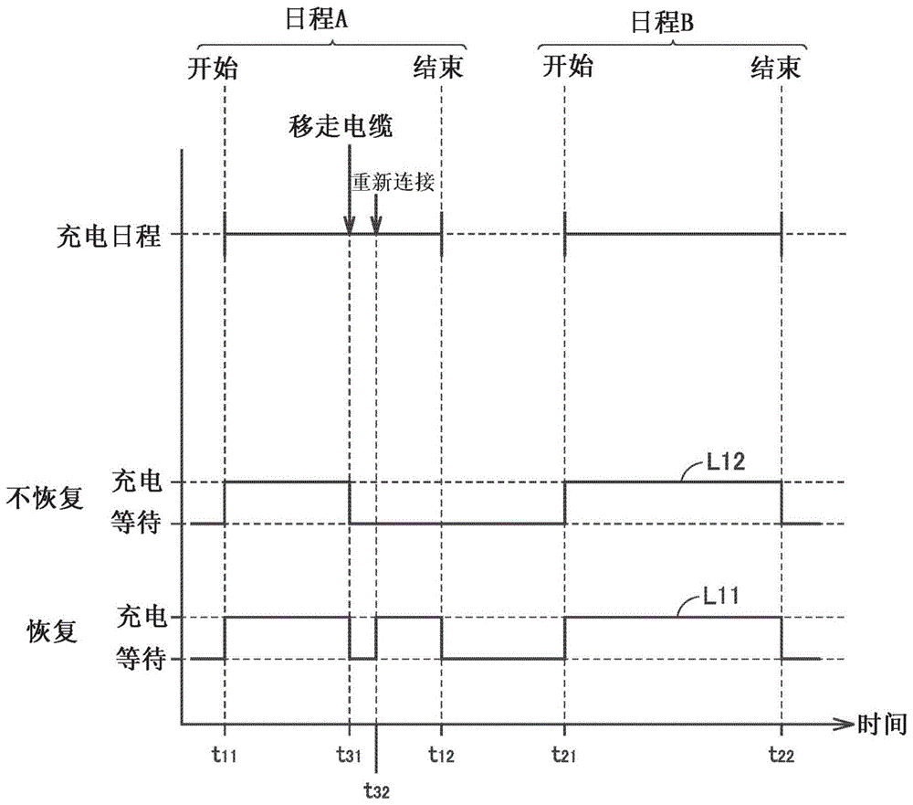
Hereinafter, the operation of the ECU150 will be described with reference to fig. 2. Fig. 2 is a schematic diagram showing an example of the timed charging performed by the ECU 150. In the present example, the timed charging with schedules a and B described below set is reserved in the ECU, and the vehicle 100 remains ready for charging. The reservation for the timed charge is not released. With respect to lines L11, L12 in fig. 2, "CHARGE" means that the vehicle 100 is charging, and "WAIT" means that the vehicle 100 is waiting, rather than charging.
Referring to fig. 2, a plurality of charging schedules (more specifically, schedules a and B) for different timing charging are set to the ECU 150. Schedule A is the charging schedule closest to the current time, and for schedule A time t11Is the start time and time t12Is the end time. Schedule B is the charging schedule that is closest to the current time after schedule A, and for schedule B time t21Is the start time and time t22Is the end time. If the timer charging is reserved, the timer charging according to schedule a (hereinafter also referred to as "timer charging a") is performed first, and the timer charging according to schedule B (hereinafter also referred to as "timer charging B") is performed thereafter.
The timer charge a is performed at time t 11. In the example of FIG. 2, at time t31The charging connector 310 of the charging cable 300 is removed from the charging inlet 110 of the vehicle 100 during the timer charging a. As a result, charging cable 300 is disconnected from vehicle 100. The ECU150 according to the present embodiment suspends the timer charge a if the charging cable 300 is disconnected from the vehicle 100 during the timer charge a.
In the example of FIG. 2, at time t31Suspend timed charging A, and at the end time of schedule A (time t)12) Previous time t32The charging connector 310 of the charging cable 300 is reconnected to the charging inlet 110 of the vehicle 100. Here, if the recovery condition is satisfied, the timer charge a is recovered as shown by a line L11. The resumed timed Charge A at the end time of Schedule A (time t)12) And finishing the process. In contrast, if the recovery condition is not satisfied when charging cable 300 is reconnected, then timed charge a ends without waiting for the end time (time t)12) As shown by line L12. When the timing charge a is so terminated halfway (i.e., before the end time), the timing charge a is not resumed.
Whether the timer charging A is resumed (line L11) or terminated (line L12), the timer charging A is terminated, and the start time of the schedule B is once reached (time t)21) Timed charging B begins and once the end time of schedule B is reached (time t)22) The timer charging B ends. In the example of fig. 2, the charging cable 300 is not disconnected during the timed charge B, and thus the timed charge B will not be suspended. However, when the charging cable 300 is disconnected during the timer charging B, the same processing as the timer charging a is performed.
As described above, if the resume condition is satisfied when the charging cable 300 is reconnected, the ECU150 according to the present embodiment resumes the suspended timed charging without terminating it. As a result, user convenience in the time charging is improved.
The resume condition is set to be satisfied in the case where the suspended timed charge a needs to be resumed. In the present embodiment, if after charging cable 300 is disconnected, charging cable 300 is reconnected before the end time of the timed charging (more specifically, the suspended timed charging) without vehicle 100 starting to travel, the resume condition is satisfied. If the user reconnects charging cable 300 before vehicle 100 begins to travel, the user is highly likely to wish to resume the suspended timed charge (i.e., the user is willing to continue the timed charge).
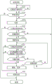
Fig. 3 is a flowchart illustrating a procedure for timed charging performed on the ECU150 according to the present embodiment. When the power switch of vehicle 100 is turned off and the timer charging is scheduled in ECU150, the process illustrated in the flowchart is started.
Referring to fig. 1 and 3, in step (hereinafter also simply referred to as "S") 111, it is determined whether the start time of the charging schedule set to ECU150 has been reached. This determination is made by the timer 153. If the start time of the charging schedule has been reached (yes in S111), the timer 153 transmits a signal (hereinafter also referred to as "start signal") for notifying the arrival of the start time to the processor 151. The processing step S111 is repeated until the start signal is transmitted (i.e., when determined as "no" in S111).
When the processor 151 receives a start signal from the timer 153, the processor 151 resumes from the sleep mode. When the start time of the charging schedule has been reached (yes at S111), the ECU150 enters the ordinary operation state, and the process proceeds to S112. At S112, ECU150 determines whether vehicle 100 is ready for charging. When the power switch of vehicle 100 is turned off and vehicle 100 and charging stand 200 are connected to each other via charging cable 300, "yes" is determined at S112, and the process proceeds to S121. When the power switch of vehicle 100 is turned on and/or charging cable 300 is disconnected from vehicle 100, no is determined at S112, and the series of processes illustrated in fig. 3 ends. In this case, the timer charging ends without being started (executed).
At S121, ECU150 turns on (becomes conductive state) a charging relay (not shown) of battery 130 and charges battery 130. As a result, the timer charging is performed. During timed charging, power is supplied to vehicle 100 (and thus battery 130) from charging station 200 through charging cable 300. The ECU150 may control the charger 120 during charging so as to supply a desired power to the battery.
At S122, it is determined whether the end time of the charging schedule set to ECU150 has been reached. This determination is made by the ECU 150. For example, the ECU150 may use a timer 153 (timer circuit) to make the above determination. However, the present disclosure is not limited thereto. The ECU150 may make the above determination using software. For example, a counter (variable) is available in the storage device 152, and the ECU150 may determine whether the counter value has reached a prescribed value while incrementing the counter for each control cycle.
When the end time of the charging schedule has been reached (yes at S122), the processing proceeds to S18. At S18, ECU150 causes a charging relay (not shown) of battery 130 to close (become a blocking state) to end charging of battery 130. As a result, the timer charging ends.
At S123, ECU150 determines the connection state (connection/disconnection) of charging cable 300. ECU150 is able to determine whether charging cable 300 of vehicle 100 is connected or disconnected based on the signals from the above-described connection sensors. In the present embodiment, when the charging connector 310 of the charging cable 300 is connected to the charging inlet 110 of the vehicle 100, "yes" is determined in S123, and the process returns to S121.
When determined as "no" at S122 and determined as "yes" at S123, the processing steps S121 to S123 are repeated for each prescribed control cycle, thereby continuously performing the timer charging. When the charging connector 310 of the charging cable 300 is pulled out from the charging inlet 110 of the vehicle 100 during the timer charging, "no" is determined at S123, and the process proceeds to S13.
At S13, for example, ECU150 causes a charging relay (not shown) of battery 130 to close (become a blocking state), thereby suspending ongoing timed charging. It should be noted that the timed charging may be suspended in any manner. The ECU150 can suspend the timed charging by controlling the switching element included in the charger 120 and stopping the output of the charger 120.
After processing step S13, it is determined at S14 whether the end time of the charging schedule set to ECU150 has been reached. The processing step S14 is the same as S122 described above. When the end time of the charging schedule has been reached (yes at S14), the processing proceeds to S17 described below. On the other hand, when the end time of the charging schedule is not reached (no at S14), the processing proceeds to S15.
At S15, ECU150 determines whether vehicle 100 has started running. When the vehicle 100 does not travel a prescribed distance or more from the position of the vehicle 100 while the charging cable 300 is disconnected, the ECU150 determines that the vehicle 100 has not started traveling (no at S15). When the vehicle 100 travels a prescribed distance or more, the ECU150 determines that the vehicle 100 has started traveling (yes at S15). The prescribed distance is a threshold value at which the ECU150 determines whether the vehicle 100 has started running, based on the threshold value. The prescribed distance may be a fixed value (e.g., about 10m) or may be variable by the user. The user may be allowed to input (and thus set) any distance to the ECU 150. The user may consider the size of the parking lot or the size of the garage to determine the prescribed distance.
The method of determining whether the vehicle 100 has started running is not limited to the above. For example, when the vehicle 100 leaves the garage (or when moving a prescribed distance away from the garage), the vehicle 100 may be determined to have started traveling. If a GPS receiver is employed as the position detection device 180, the ECU150 can acquire the position of the vehicle 100 based on the output of the GPS receiver. The vehicle 100 may also be determined to have started running when the running speed (vehicle speed) of the vehicle 100 reaches a prescribed value or higher. If a rotation amount sensor is employed as the position detection device 180, the ECU150 can acquire the rotation amount of the drive wheel W per unit time (i.e., the vehicle speed of the vehicle 100) based on the output of the rotation amount sensor. Further, the shift position may be considered in determining whether the vehicle 100 has started running.
When the determination at S15 is "no," the process proceeds to S16. At S16, ECU150 determines whether charging connector 310 of charging cable 300 is reconnected to charging inlet 110 of vehicle 100. When the charging cable 300 is connected to the charging inlet 110, it is determined as yes at S16, and the process returns to S121. As a result, the battery 130 is charged at S121 and the timing charge is resumed. The condition determined as "yes" at S16 means that the recovery condition is satisfied. In the present embodiment, after the charging cable 300 is disconnected (no at S123), if the vehicle 100 does not start running (no at S15) and the charging cable 300 is reconnected (yes at S16) before the end time of the timer charging (no at S14), the recovery condition is satisfied. Therefore, the charging is resumed at the timing suspended at S13.
When the charging cable 300 remains disconnected, the determination at S16 is no, and the process returns to S14. During the period of time from S14 to S16, which has been determined to be "no", the processing steps S14 to S16 are repeated for each prescribed control cycle. When the vehicle 100 starts running within the period (yes at S15), the processing proceeds to S17.
When it is determined as "yes" at S14 or S15 and the process proceeds to S17, the charging at the timing suspended at S13 will not be resumed (i.e., ended halfway). At S17, ECU150 notifies and records that the timer charging has ended halfway. The ECU150 may display information (e.g., text and images) on a notification device 170 (e.g., a display device of a smartphone) for notifying the user that the timer charging has ended halfway. ECU150 may change the value of the flag stored in storage device 152 (the initial value is off) to on, thereby recording that the timed charge has ended halfway in storage device 152. It should be noted that the manner of notifying the user is not limited to displaying the above information. The information may be communicated to the user by sound (including speech) or by illuminating a defined light (including blinking).
After the processing step S17, the process proceeds to S18 described above. As a result, the timer charging ends. It should be noted that the ECU150 may notify and record as above after the timed charging ends (S17). The time of notification and recording as above may be any time as long as it is after the determination of "yes" at S15. The user can confirm from the notification and the record that the timed charge has ended halfway (and thus the timed charge will not resume).
As described above, the ECU150 (vehicle control apparatus) according to the present embodiment includes the following execution unit, recovery processing unit, and end processing unit. The execution unit is configured to perform the timer charging using a preset start time and end time (S111, S112, S14, S18). When the predetermined recovery condition is not satisfied (yes at S15), the end processing unit is configured to notify or record (both in the present embodiment) that the timer charging has ended halfway (S17).
When the charging cable is disconnected during the timer charging (no at S123), the resume processing unit is configured to suspend the timer charging (S13), and when a predetermined resume condition is satisfied (yes at S16), resume the suspended timer charging without terminating it (S121). When the predetermined resume condition is satisfied, the suspended timed charging will be automatically resumed without user operation. As a result, user convenience in the time charging is improved.
When it is sensed that the vehicle 100 has started running (more specifically, when the vehicle 100 runs a prescribed distance or longer) in the period from the disconnection of the charging cable 300 (no at S123) to the reconnection of the charging cable 300 (yes at S16), the recovery processing unit is configured to determine that the predetermined recovery condition is not satisfied (yes at S15) and terminate the timer charging at S18. As a result, the control of the vehicle smoothly transitions from the charging control to the running control.
The recovery condition is not limited to the above condition. The resume conditions may be arbitrarily set as long as they include the reconnection of the charging cable 300 after the timed charging pause and before the end time. For example, S15 may be skipped in the process of fig. 3, and the resume condition (i.e., resuming the timed charge suspended at S13) may always be satisfied when the charging cable 300 is reconnected after the timed charge is suspended and before the end time. Further, the process of fig. 3 may be modified as follows.
Fig. 4 is a flowchart illustrating a procedure for charging the timing according to modification 1. The process of fig. 4 adopts S151 instead of S15 in the process of fig. 3. Referring to fig. 4, at S151, ECU150 determines whether a prescribed time period has elapsed since charging cable 300 has been disconnected (e.g., no at S123). For example, the ECU150 may use the timer 153 to make the above determination. However, the present disclosure is not limited thereto. The ECU150 may use software to make the above determination. The prescribed time period may be a fixed value (e.g., about 5 minutes) or may be user modifiable. The user may be allowed to input (and set accordingly) an arbitrary time to the ECU 150. In modification 1, before the end time of the timer charging (no at S14), when the charging cable 300 is reconnected (yes at S16) without a prescribed time period elapsing since the charging cable 300 was disconnected (no at S151), the recovery condition is satisfied. Therefore, the charging is resumed at the timing suspended at S13 (S121). A user who immediately reconnects charging cable 300 without having it disconnected for a period of time would most likely wish to resume the suspended timed charging.
Fig. 5 is a flowchart illustrating a procedure for charging the timing according to modification 2. The process of fig. 5 employs S151 of fig. 4 in addition to S15 of fig. 3. Referring to fig. 5, in modification 2, before the end time of the timer charging (no at S14), when the charging cable 300 is reconnected (yes at S16) without a lapse of a prescribed time period since the charging cable 300 was disconnected (no at S123) and the vehicle 100 does not start running (no at S151 and S15), the recovery condition is satisfied. Therefore, the timed charging suspended at S13 is resumed (S121).
In each of the above processes of fig. 3 to 5, at S123, S16 is determined whether the charging cable 300 is connected to the vehicle 100. However, if charging cable 300 is detachable from charging station 200, it may be determined at S123, S16 whether charging cable 300 is connected to vehicle 100 and charging station 200. In this case, when charging cable 300 is connected to vehicle 100 and charging station 200, S16 is determined as "yes" at S123. When charging cable 300 is disconnected from any one of vehicle 100 and charging stand 200, at S123, S16 is determined as no. ECU150 is able to determine the connection state (connection/disconnection) of charging cable 300 based on a signal (e.g., CPLT signal) from charging cable 300.
If step S17 in fig. 3 to 5 is not required, the step may be excluded from the processing. Further, the ECU150 may notify or record as above.
The charging condition (e.g., charging schedule and amount of charge) of the timer charging to be resumed when the resumption condition is satisfied may be different from the charging condition before the timer charging is suspended. For example, the charging condition may be reconfigured before resuming the timed charging so that the amount of the electric power that is not charged at the time of the timed charging suspension (hereinafter also simply referred to as "suspension period") is replenished by the resumed timed charging.
Fig. 6 is a schematic diagram for illustrating a first example of a replenishment method of the amount of the insufficient electric power during the suspension period. Referring to FIG. 6, time t12Is the end time of the timer charge a set before the timer charge a is suspended. Time t13Is the end time of the change to the timing charge a to be resumed. In the example of fig. 6, when it is determined as "yes" at S16 (the recovery condition is satisfied) in the process illustrated in any one of fig. 3 to 5, the ECU150 at time t32The end time of the timed charge a is changed. The ECU150 delays the end time of the timed charge a and resumes the timed charge a to replenish the amount of electric power D1 (i.e., the charge a is suspended at the timed charge a (time t)31To time t32) The amount of the electric power not charged at that time). End time from time t12Becomes time t13. As a result, the timer charging a is performed as indicated by a line L21 in fig. 6.
In the first example as above, the ECU150 includes a first changing unit configured to, when a predetermined recovery condition is satisfied, change the end time of the recovered timed charge so as to replenish at least a part of the amount of the electric power that was not charged at the time of the timed charge suspension. The end time of the timed charge a to be resumed is delayed by the first changing unit, and the amount of charge that is insufficient due to suspension can be replenished by the resumed timed charge a. For example, in a period (time t) extended by changing the end time as described above12To time t13) The amount of electric power C1 charged during this period is the same as the amount of electric power D1. However, the present disclosure is not limited thereto. In addition to the amount of power D1, the SOC of battery 130 may also be considered when determining the end time of the resumed timed charge a.
It should be noted that it is not always beneficial for the user to allow the user to change the charging schedule (more specifically, change the end time) because the charging schedule of the timer charging a can be set according to a time period in which the electricity fee is inexpensive. Thus, the user can be allowed to select (i.e., set to the ECU 150) in advance one of a mode in which the charging schedule is allowed to be changed (hereinafter also referred to as "change allowed mode") and a mode in which the charging schedule is not allowed to be changed (hereinafter also referred to as "change not allowed mode"). For example, when the user selects permission to change modes via input device 160, the value of the permission flag in storage device 152 may be set to on. When the user selects the disallow change mode via input device 160, the value of the allow flag in storage device 152 may be set to off. The first changing unit included in the ECU150 may change the end time of the timed charge a if the value of the permission flag is on when the recovery condition is satisfied, and may not change the end time of the timed charge a if the value of the permission flag is off when the recovery condition is satisfied (see fig. 6). It should be noted that the value of the enable flag (initial value) may be on or off before the user selects the mode.
Fig. 7 is a schematic diagram for illustrating a second example of a replenishment method of the amount of electric power that is not charged during the suspension period. With respect to the line L22 in fig. 7, "normal charging" means normal timed charging, and "quick charging" means charging in which the amount of charge per unit time is larger than that of normal charging in accordance with the charging.
Referring to fig. 7, the timed charge a before the pause is the normal charge. However, in the example of fig. 7, time t when illustrated in any one of fig. 3 to 5 described above32If yes in process step S16 (the recovery condition is satisfied), ECU150 changes the charging rate of timer charge a (i.e., the amount of charge per unit time). ECU150 increases the amount of charge per unit time by timer charge a to replenish the suspension of timer charge a (time t)31To time t32) The amount of electric power D1 not yet charged, and the timer charge a is resumed thereafter. As a result, the timer charging a is performed as indicated by a line L22 in fig. 7. The recovered timed charge A is a fast charge, allowing for the recovered timed charge to be passedElectricity a replenishes the amount of charge that is insufficient due to the suspension.
In the above second example, the ECU150 includes a second changing unit configured to change the amount of charge per unit time of the resumed timed charge so as to replenish at least a part of the amount of the non-charged power at the time of the timed charge suspension, when a predetermined resumption condition is satisfied. The second changing unit changes the charging rate of the timed charge a, thereby allowing the amount of charge insufficient due to the suspension to be replenished by the resumed timed charge without changing the charging schedule set by the user. The second changing unit controls, for example, a switching element included in the charger 120, thereby adjusting the amount of charge per unit time. For example, the amount of electric power C2 increased by changing the amount of charge per unit time as described above is the same as the amount of electric power D1. However, the present disclosure is not limited thereto. The second changing unit may consider the SOC of the battery 130 in addition to the amount of electric power D1 when determining the amount of charge per unit time of the recovered timing charge a.
The ECU150 may include both the first changing unit and the second changing unit described above. When it is determined that the predetermined recovery condition is satisfied, the ECU150 may change not only the charging rate of the timed charge a but also the end time of the timed charge a.
The ECU150 may be configured to replenish the amount of electric power that was not charged during the suspension period (i.e., the amount of electric power that was not charged during the suspension of the timed charge) by changing the charging schedule of other timed charges set to the ECU150 while the timed charge was suspended. Fig. 8 is a schematic diagram for illustrating a third example of a replenishment method of the amount of electric power that is not charged during the suspension period.
Referring to FIG. 8, time t21Is the start time of the timed charge B before the change. Time t23Is the start time of the changed timed charge B. In the example of fig. 8, charge a is timed at time t when in process step S18 illustrated in any of fig. 3 to 5 described above12When finished, the ECU150 changes the start time of the timer charge B. ECU150 advances the start time of timing charge B to replenish the suspension of timing charge a (time t)31To time t32) Temporarily not charged electric powerAmount D1. Start time from time t21Instead of time t23. As a result, the timer charging is performed as indicated by a line L23 in fig. 8.
In the third example as described above, the ECU150 includes a third changing unit configured to, when a predetermined recovery condition is satisfied, change at least one of the start time and the end time of the timed charge B (second timed charge) so as to replenish, by the timed charge B, at least a part of the uncharged amount at the time when the timed charge a (first timed charge) is suspended. The third changing unit advances the start of the timed charge B, thereby allowing the amount of charge that is insufficient due to the suspension of the timed charge a to be replenished by the timed charge B. In a period extended by changing the start time (time t)23To time t21) The amount of electric power C3 charged during this period is the same as the amount of electric power D1, for example. However, the present disclosure is not limited thereto. When determining the start time of the timed charge B, the SOC of the battery 130 may be considered in addition to the amount of electric power D1.
The user may be allowed to select (i.e., set to the ECU 150) in advance one of the above-described change-permitted mode and change-not-permitted mode. A third changing unit included in the ECU150 may change the start time of the timed charge B (see fig. 8) if the value of the permission flag is on when the recovery condition is satisfied, and may not change the start time of the timed charge B if the value of the permission flag is off when the recovery condition is satisfied.
Although the ECU150 advances the start time of the timed charge B in the example of fig. 8, the ECU150 may delay the end time of the timed charge B. Alternatively, the ECU150 may change both the start time and the end time of the timed charge B. The ECU150 may include the above-described first changing unit, second changing unit, and third changing unit. ECU150 may be configured to supplement a portion of amount of electric power D1 with at least one of amount of electric power C1 illustrated in fig. 6 and amount of electric power C2 illustrated in fig. 7, while supplementing the remaining portion of amount of electric power D1 with amount of electric power C3 illustrated in fig. 8.
The above-described "first changing unit", "second changing unit", and "third changing unit" are embodied, for example, in the processor 151 shown in fig. 1 and programs in the storage device 152 executed by the processor 151. However, the present disclosure is not limited thereto. These units may be embodied by dedicated hardware (electronic circuitry).
While embodiments of the present disclosure have been described, it is to be understood that the embodiments disclosed herein are illustrative and not restrictive in every respect. The scope of the present disclosure is defined by the scope of the claims, and is intended to include any modifications within the scope and meaning equivalent to the scope of the claims.