CN111194188A - Easy Start of Cannulated Bone Screws - Google Patents
Easy Start of Cannulated Bone Screws Download PDFInfo
- Publication number
- CN111194188A CN111194188A CN201880065566.9A CN201880065566A CN111194188A CN 111194188 A CN111194188 A CN 111194188A CN 201880065566 A CN201880065566 A CN 201880065566A CN 111194188 A CN111194188 A CN 111194188A
- Authority
- CN
- China
- Prior art keywords
- surgical screw
- threads
- distal end
- tapered tip
- screw
- Prior art date
- Legal status (The legal status is an assumption and is not a legal conclusion. Google has not performed a legal analysis and makes no representation as to the accuracy of the status listed.)
- Granted
Links
Images


Classifications
-
- A—HUMAN NECESSITIES
- A61—MEDICAL OR VETERINARY SCIENCE; HYGIENE
- A61B—DIAGNOSIS; SURGERY; IDENTIFICATION
- A61B17/00—Surgical instruments, devices or methods
- A61B17/56—Surgical instruments or methods for treatment of bones or joints; Devices specially adapted therefor
- A61B17/58—Surgical instruments or methods for treatment of bones or joints; Devices specially adapted therefor for osteosynthesis, e.g. bone plates, screws or setting implements
- A61B17/68—Internal fixation devices, including fasteners and spinal fixators, even if a part thereof projects from the skin
- A61B17/84—Fasteners therefor or fasteners being internal fixation devices
- A61B17/86—Pins or screws or threaded wires; nuts therefor
- A61B17/8625—Shanks, i.e. parts contacting bone tissue
- A61B17/863—Shanks, i.e. parts contacting bone tissue with thread interrupted or changing its form along shank, other than constant taper
-
- A—HUMAN NECESSITIES
- A61—MEDICAL OR VETERINARY SCIENCE; HYGIENE
- A61B—DIAGNOSIS; SURGERY; IDENTIFICATION
- A61B17/00—Surgical instruments, devices or methods
- A61B17/56—Surgical instruments or methods for treatment of bones or joints; Devices specially adapted therefor
- A61B17/58—Surgical instruments or methods for treatment of bones or joints; Devices specially adapted therefor for osteosynthesis, e.g. bone plates, screws or setting implements
- A61B17/68—Internal fixation devices, including fasteners and spinal fixators, even if a part thereof projects from the skin
- A61B17/84—Fasteners therefor or fasteners being internal fixation devices
- A61B17/86—Pins or screws or threaded wires; nuts therefor
- A61B17/8625—Shanks, i.e. parts contacting bone tissue
- A61B17/8635—Tips of screws
-
- A—HUMAN NECESSITIES
- A61—MEDICAL OR VETERINARY SCIENCE; HYGIENE
- A61B—DIAGNOSIS; SURGERY; IDENTIFICATION
- A61B17/00—Surgical instruments, devices or methods
- A61B17/56—Surgical instruments or methods for treatment of bones or joints; Devices specially adapted therefor
- A61B17/58—Surgical instruments or methods for treatment of bones or joints; Devices specially adapted therefor for osteosynthesis, e.g. bone plates, screws or setting implements
- A61B17/68—Internal fixation devices, including fasteners and spinal fixators, even if a part thereof projects from the skin
- A61B17/84—Fasteners therefor or fasteners being internal fixation devices
- A61B17/86—Pins or screws or threaded wires; nuts therefor
- A61B17/864—Pins or screws or threaded wires; nuts therefor hollow, e.g. with socket or cannulated
-
- A—HUMAN NECESSITIES
- A61—MEDICAL OR VETERINARY SCIENCE; HYGIENE
- A61B—DIAGNOSIS; SURGERY; IDENTIFICATION
- A61B90/00—Instruments, implements or accessories specially adapted for surgery or diagnosis and not covered by any of the groups A61B1/00 - A61B50/00, e.g. for luxation treatment or for protecting wound edges
- A61B90/08—Accessories or related features not otherwise provided for
-
- A—HUMAN NECESSITIES
- A61—MEDICAL OR VETERINARY SCIENCE; HYGIENE
- A61L—METHODS OR APPARATUS FOR STERILISING MATERIALS OR OBJECTS IN GENERAL; DISINFECTION, STERILISATION OR DEODORISATION OF AIR; CHEMICAL ASPECTS OF BANDAGES, DRESSINGS, ABSORBENT PADS OR SURGICAL ARTICLES; MATERIALS FOR BANDAGES, DRESSINGS, ABSORBENT PADS OR SURGICAL ARTICLES
- A61L31/00—Materials for other surgical articles, e.g. stents, stent-grafts, shunts, surgical drapes, guide wires, materials for adhesion prevention, occluding devices, surgical gloves, tissue fixation devices
- A61L31/02—Inorganic materials
- A61L31/022—Metals or alloys
-
- A—HUMAN NECESSITIES
- A61—MEDICAL OR VETERINARY SCIENCE; HYGIENE
- A61B—DIAGNOSIS; SURGERY; IDENTIFICATION
- A61B17/00—Surgical instruments, devices or methods
- A61B17/56—Surgical instruments or methods for treatment of bones or joints; Devices specially adapted therefor
- A61B17/58—Surgical instruments or methods for treatment of bones or joints; Devices specially adapted therefor for osteosynthesis, e.g. bone plates, screws or setting implements
- A61B17/68—Internal fixation devices, including fasteners and spinal fixators, even if a part thereof projects from the skin
- A61B17/84—Fasteners therefor or fasteners being internal fixation devices
- A61B17/86—Pins or screws or threaded wires; nuts therefor
- A61B17/8605—Heads, i.e. proximal ends projecting from bone
- A61B17/861—Heads, i.e. proximal ends projecting from bone specially shaped for gripping driver
- A61B17/8615—Heads, i.e. proximal ends projecting from bone specially shaped for gripping driver at the central region of the screw head
-
- A—HUMAN NECESSITIES
- A61—MEDICAL OR VETERINARY SCIENCE; HYGIENE
- A61B—DIAGNOSIS; SURGERY; IDENTIFICATION
- A61B17/00—Surgical instruments, devices or methods
- A61B17/56—Surgical instruments or methods for treatment of bones or joints; Devices specially adapted therefor
- A61B17/58—Surgical instruments or methods for treatment of bones or joints; Devices specially adapted therefor for osteosynthesis, e.g. bone plates, screws or setting implements
- A61B17/68—Internal fixation devices, including fasteners and spinal fixators, even if a part thereof projects from the skin
- A61B17/84—Fasteners therefor or fasteners being internal fixation devices
- A61B17/86—Pins or screws or threaded wires; nuts therefor
- A61B17/8645—Headless screws, e.g. ligament interference screws
-
- A—HUMAN NECESSITIES
- A61—MEDICAL OR VETERINARY SCIENCE; HYGIENE
- A61B—DIAGNOSIS; SURGERY; IDENTIFICATION
- A61B90/00—Instruments, implements or accessories specially adapted for surgery or diagnosis and not covered by any of the groups A61B1/00 - A61B50/00, e.g. for luxation treatment or for protecting wound edges
- A61B90/08—Accessories or related features not otherwise provided for
- A61B2090/0807—Indication means
Landscapes
- Health & Medical Sciences (AREA)
- Orthopedic Medicine & Surgery (AREA)
- Surgery (AREA)
- Life Sciences & Earth Sciences (AREA)
- Veterinary Medicine (AREA)
- Public Health (AREA)
- General Health & Medical Sciences (AREA)
- Animal Behavior & Ethology (AREA)
- Heart & Thoracic Surgery (AREA)
- Molecular Biology (AREA)
- Medical Informatics (AREA)
- Biomedical Technology (AREA)
- Engineering & Computer Science (AREA)
- Nuclear Medicine, Radiotherapy & Molecular Imaging (AREA)
- Neurology (AREA)
- Pathology (AREA)
- Oral & Maxillofacial Surgery (AREA)
- Chemical & Material Sciences (AREA)
- Inorganic Chemistry (AREA)
- Vascular Medicine (AREA)
- Epidemiology (AREA)
- Surgical Instruments (AREA)
- Materials For Medical Uses (AREA)
Abstract
The present invention provides a surgical screw for fixation into bone or soft tissue. The surgical screw includes a hollow body having a proximal end and a distal end. The distal end of the hollow body has a tapered tip, and a plurality of threads extend around the exterior of the hollow body. An introducer extends distally from the tapered tip and has a diameter (which may be variable or constant) that is less than the diameter of the tapered tip. The surgical screw is hollow such that a channel extends through the body from the proximal end to (and sometimes through) the distal end.
Description
Cross Reference to Related Applications
This application claims priority from U.S. provisional patent application serial No. 62/569,770 entitled "Easy Start locked Bone screen" filed on 9/10/2017 and U.S. provisional patent application serial No. 62/599,228 entitled "Easy Start locked Bone screen" filed on 15/12/2017.
Technical Field
The present disclosure relates generally to a surgical fixation device and, more particularly, to a hollow screw for fixation into bone or soft tissue.
Background
In orthopaedic surgery, screws are commonly used to fix a biological material or other object (e.g., an implant) in a desired position relative to bone. For example, screws are used to attach bone pieces to existing bone or to secure soft tissue to bone or soft tissue. Initial screwing of the screw into the bone or bone block can be difficult. Therefore, in some procedures, a guide hole is required to help align the screw. As is well known in the surgical field, the guide holes are smaller in depth and diameter than the screws to provide guidance to the screws, while still being narrow enough to allow sufficient threads of the screws to penetrate bony interference sites. A bone hammer may also be used to hammer the screw into a depth sufficiently deep to allow the threads to penetrate the bony interference site.
Drilling guide holes requires additional operating time and additional surgical instruments. While hammering a screw into bone using a bone hammer may take less time and require less instrumentation, the accuracy is less. Hammering a screw into bone carries an even greater risk that the screw will not be aligned with the desired fixation location. Accordingly, there is a need for a surgical screw that does not require the use of a pilot hole or bone hammer while remaining securely and reliably fixed within the bone.
Disclosure of Invention
The present invention relates to a surgical screw. The surgical screw includes features for reducing the torque required to start the screw or introduce the screw into the anatomy. According to one aspect, a surgical screw includes a hollow body having a proximal end and a distal end. The distal end of the hollow body may have a tapered tip and a plurality of threads that may extend around the exterior of the hollow body from a location at, adjacent to, or proximal to the distal end to a location at, adjacent to, or distal to the proximal end. The introducer extends distally from the tapered tip and has a diameter (which may be constant or variable) that is less than the diameter of the tapered tip. The surgical screw is hollow such that the channel extends through the body from the proximal end to the distal end.
According to another aspect, a surgical screw includes a hollow body having a proximal end and a distal end, the hollow body having a tapered tip. A plurality of threads (from the locations described above) extend around the exterior of the hollow body. The plurality of threads includes a primary thread and a secondary thread. The lead of the primary thread is greater than the pitch of the plurality of threads. The introducer extends distally from the tapered tip. The surgical screw is hollow such that the channel extends through the body from the proximal end to the distal end.
It should be understood that all combinations of the foregoing concepts and additional concepts discussed in greater detail below (provided such concepts do not contradict each other) are considered a part of the inventive subject matter disclosed herein. In particular, all combinations of claimed subject matter appearing at the end of this disclosure are considered part of the inventive subject matter disclosed herein. It is also to be understood that the terms explicitly employed herein, which may also appear in any disclosure incorporated by reference, are to be accorded the most consistent meanings with the specific concepts disclosed herein.
These and other aspects of the invention will be apparent from and elucidated with reference to the embodiments described hereinafter.
Drawings
One or more aspects of the present invention are particularly pointed out and distinctly claimed as examples in the claims at the conclusion of the specification. The foregoing and other objects, features, and advantages of the invention will be apparent from the following description taken in conjunction with the accompanying drawings in which:
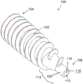
FIG. 1 is a schematic perspective proximal view of a surgical screw according to one embodiment;
FIG. 2 is a distal perspective schematic view of a surgical screw according to one embodiment;
FIG. 3 is a side schematic view of a surgical screw according to one embodiment;
FIG. 4 is a perspective schematic view of a surgical screw according to an alternative embodiment;
FIG. 5 is a side schematic view of a surgical screw according to an alternative embodiment;
FIG. 6 is a distal perspective schematic view of a surgical screw according to an alternative embodiment;
FIG. 7 is a schematic distal end view of a surgical screw according to an alternative embodiment;
FIG. 8 is a distal perspective schematic view of a surgical screw according to one embodiment;
FIG. 9 is a side schematic view of a surgical screw according to an alternative embodiment; and
FIG. 10 is a side schematic view of a surgical screw according to another alternative embodiment;
FIG. 11 is a side schematic view of a surgical screw according to yet another alternative embodiment;
FIG. 12 is a close-up schematic view of an exemplary embodiment of a surgical screw having a single head; and
fig. 13 is a close-up schematic view of an exemplary embodiment of a surgical screw having dual heads.
Detailed Description
Aspects of the present invention and certain features, advantages and details thereof are explained more fully hereinafter with reference to the non-limiting examples that are illustrated in the accompanying drawings. Descriptions of well-known structures are omitted so as to not unnecessarily obscure the present invention in detail. It should be understood, however, that the detailed description and the specific non-limiting examples, while indicating aspects of the present invention, are given by way of illustration only, and not by way of limitation. Various substitutions, modifications, additions and/or arrangements within the spirit and/or scope of the basic inventive concept will be apparent to those skilled in the art in light of this disclosure.
Referring now to the drawings, in which like numerals refer to like parts throughout, fig. 1 shows a perspective proximal schematic view of a surgical screw 100 according to one embodiment. The surgical screw 100 includes a body 102 extending between a proximal end 104 and a distal end 106. Surgical screw 100 may be constructed of any suitable biocompatible material, such as titanium or magnesium, and may be manufactured according to conventional manufacturing methods, such as machining (as will be understood by those of ordinary skill in the art in view of this disclosure). Surgical screw 100 may also be constructed of a biocomposite material and manufactured via injection molding (as will be understood by those of ordinary skill in the art in view of this disclosure).
As shown in fig. 1, the body 102 includes features 108 at the proximal end 104 that allow the surgical screw 100 to be torqued. Specifically, the feature 108 is located on an outer surface 110 of the proximal end 104. For example, the feature 108 may be a feature of any conventional screw head, as well as a feature of an unconventional geometry (e.g., Tri-Lobe screwdriver geometry). In the depicted embodiment, the features 108 have a hexagonal cross-section. As shown in fig. 1, the surgical screw 100 is hollow such that a channel 112 extends through the body 102 from a feature 108 at an outer surface 110 of the proximal end 104 to the distal end 106.
Turning now to fig. 2, a distal perspective schematic view of a surgical screw 100 is shown, according to one embodiment. In the depicted embodiment, the body 102 of the surgical screw 100 includes a tip 114 at the distal end 106. In fig. 2, the tip 114 is a tapered region (at least partially tapered, may taper all the way to the distal-most end, and may include a constant, variable (incremental or decremental) taper, or more than one taper (separable from the non-tapered portion) with the same or different taper values) such that the body 102 tapers toward the distal end 106. As mentioned above, surgical screw 100 is hollow. Fig. 2 shows a channel 112 extending through the body 102 of the surgical screw 100 to a tip 114 at the distal end 106. Specifically, channel 112 extends from feature 108 at proximal end 104 to an opening 116 on an outer surface 118 of tip 114.
Still referring to fig. 2, surgical screw 100 includes a guide 120 at tip 114. In the depicted embodiment, introducer 120 is an elongated extension extending from tip 114. In the depicted embodiment, introducer 120 is a narrow cylinder extending from tip 114 at distal end 106. As shown, the introducer 120 is also hollow such that the introducer 120 has an outer surface 118 and an opening 116 to the passage 112 extending through the body 102. The guide 120 allows for easier insertion of the surgical screw 100 because the guide 120 can be used to align the surgical screw 100 at a desired bone hole location.
Referring now to fig. 3, a side schematic view of a surgical screw 100 is shown, according to one embodiment. As shown in fig. 3, surgical screw 100 includes a plurality of threads 122 along the length of body 102. As with all conventional screws, the adjacent threads 122 have a pitch p and a base diameter d. However, the pitch p, and thus the base diameter d, of the depicted embodiment of the surgical screw 100 may be variable/non-constant (alternatively, the pitch may be variable and the base diameter may be constant, or vice versa, and the pitch and/or base diameter may be variable within a body of a certain length and constant within a body of another length). In other words, the threads 122 of the surgical screw 100 are not evenly spaced. In one embodiment, the pitch p increases from the proximal end 104 to the distal end 106, while the base diameter d increases from the distal end 106 to the proximal end 104. For example, as shown in fig. 3, the pitch p1 at the distal end 106 is greater than the pitch p2 at the proximal end 104, and the base diameter at the distal end 106 is less than the base diameter at the proximal end 104.
Still referring to fig. 3, the threads 122 of the surgical screw 100 are double start threads. A double start thread is two threads that are 180 degrees opposite. As shown in fig. 3, the surgical screw 100 includes a staggered start head 124. In other words, the secondary threads 128 begin 180 degrees later than the primary threads 126. As shown in fig. 13, when the surgical screw 100 has a double start or staggered start 124, the main thread 122A has a lead L that is greater than the pitch p of the threads 122(122A, 122B). The surgical screw 100 may also have three heads or any additional multiple heads (not shown as would be understood by one of ordinary skill in the art in view of this disclosure) or a single head (fig. 12) wherein the lead L and the pitch p are equal. In one embodiment, as shown in FIG. 3, the primary thread 126 has a reduced surface area A. The reduced surface area a reduces resistance and reduces torque during initial engagement with bone.
Turning now to fig. 4-11, various schematic views of a surgical screw 100 are shown, according to an alternative embodiment. First, in fig. 4, a perspective schematic view of a surgical screw 100 according to an alternative embodiment is shown. As with the surgical screw 100 of fig. 1-3, the surgical screw 100 of fig. 4 includes a body 102 extending between a proximal end 104 and a distal end 106, the body having a feature 108 on an outer surface 110 at the proximal end 104 that allows the surgical screw 100 to be torqued. As shown in fig. 4, the surgical screw 100 is hollow such that a channel 112 extends through the body 102 from the feature 108 at the outer surface 110 of the proximal end 104 to the distal end 106. Like the surgical screw 100 of fig. 1-3, the surgical screw 100 shown in fig. 4-11 may be constructed of any suitable biocompatible material, such as titanium or magnesium, or a biocomposite material, and may be manufactured according to conventional manufacturing methods, such as machining or injection molding.
Fig. 5 shows a side schematic view of a surgical screw 100 according to an alternative embodiment. The surgical screw 100 shown in fig. 5 has threads 122 extending along the body 102 of the screw 100. Adjacent threads 122 in the depicted embodiment have a constant (i.e., equal) pitch p. However, the surgical screw 100 may also have threads 122 with variable pitch p1, p2, as shown in the embodiment in fig. 3. The embodiment of the surgical screw 100 in fig. 5 also has a thread 122 having a base diameter d that tapers from the proximal end 104 to the distal end 106. In particular, the base diameter d decreases from the proximal end 104 to the distal end 106 (in some embodiments, its diameter may decrease constantly, and in other embodiments, its diameter may decrease non-constantly).
Still referring to fig. 5, an embodiment of the surgical screw 100 further includes a double start thread (i.e., staggered start head) 124. As described above, the double-start threads 124 include the primary threads 126 that are 180 degrees opposite the secondary threads 128 such that the secondary threads 128 start 180 degrees later (i.e., around the exterior of the body 102) than the primary threads 126. However, in other embodiments, the secondary thread 128 may start at least 5 degrees and at most 360 degrees later than the primary thread 126. The primary and secondary threads 126, 128 have reduced surface areas a1, a2 to reduce drag and reduce torque during initial engagement with bone.
Turning now to fig. 6-7, a distal end and a distal perspective schematic view of a surgical screw 100 according to an alternative embodiment are shown. In the depicted embodiment of surgical screw 100, primary thread 126 and secondary thread 128 are chamfered. The chamfer removes the leading edges of the primary and secondary threads, further reducing their surface areas a1, a 2. As shown in fig. 6, the chamfer forms a first sharp edge 130 on the primary thread 126 and a second sharp edge 132 on the secondary thread 128. The sharp edges 130, 132 allow for better engagement between the surgical screw 100 and bone. In the depicted embodiment, the distal portion 134 of the primary thread 126 is configured such that the surface area a1 of the primary thread 126 is further reduced as compared to the surface area a2 of the secondary thread 128. In further embodiments, when surgical screw 100 is used to engage soft tissue relative to bone, a radius is used instead of a chamfer.
Referring now to fig. 8, a distal perspective schematic view of a surgical screw 100 is shown, according to one embodiment. In the depicted embodiment, the surgical screw 100 includes a notch feature 136 at the distal end 106. In one embodiment, as shown in fig. 8, a notch feature 136 extends from the introducer 120 at the distal end 106 of the surgical screw 100. In the depicted embodiment, the notch feature 136 is a notch extending generally tangentially from the introducer 120. When the bone is very hard, the notch feature 136 may be hammered into the bone. For example, the surgeon aligns the guide 120 at the desired bone hole location and hammers the proximal end 104 of the surgical screw 100 so that the guide 120 and notch feature 136 engage the bone. In another embodiment, notch feature 136 is used to find a gap between the main bone and the implant when surgical screw 100 is rotated. When notch feature 136 finds a gap, it guides primary thread 126 to the desired area, and surgical screw 100 may be rotated and installed without hammering.
Turning now to fig. 9-10, a side schematic view of a surgical screw 100 is shown according to further embodiments. In the embodiment shown in fig. 9-10, the opening 116 to the channel 112 at the distal end 106 (introducer 120) of the surgical screw 100 is solid or replaced with a solid feature 138. Solid features 138 may be circular, as shown in fig. 9, or solid features 138 may have any other suitable geometry. For example, the solid feature 138 may be a drill tip 140, as shown in FIG. 10. In the embodiment shown in fig. 9-10, the solid features 138 are not hollow. However, in alternative embodiments, the hollows may also be removed completely (as shown in fig. 9 to 10) or only partially. In other words, the solid features 138 may be completely solid or only partially solid.
Referring now to fig. 11, a side view schematic diagram of a surgical screw 100 is shown, according to yet another embodiment. In the depicted embodiment, the surgical screw 100 includes one or more external markings 142 along the body 102 between the proximal end 104 and the distal end 106. The external markings 142 of the surgical screw 100 in fig. 11 are depth indicator markings 142. During rotation and installation of surgical screw 100, depth indicator markings 142 are visible to the surgeon (or other user). Depth indicator markings 142 allow the surgeon to determine the depth of surgical screw 100 within bone or soft tissue. In the depicted embodiment, the depth indicator markings 142 are circumferential markings extending around the exterior of the surgical screw 100. However, the depth indicator markings 142 may be placed anywhere along the exterior of the surgical screw 100 such that they are visible to the surgeon (or other user). As shown in fig. 11, the depth indicator markings 142 may include a plurality of markings 142 spaced at equidistant intervals (e.g., 5mm), a single depth marking, or a plurality of markings spaced at irregular intervals, as desired, and may be made of or coated with radiographic material.
All definitions, as defined and used herein, should be understood to take precedence over dictionary definitions, definitions in documents incorporated by reference, and/or ordinary meanings of the defined terms.
While various embodiments have been described and illustrated herein, those of ordinary skill in the art will readily envision a variety of other means and/or structures for performing the function and/or obtaining the results and/or one or more of the advantages described herein, and each of such variations and/or modifications is deemed to be within the scope of the embodiments described herein. More generally, those skilled in the art will readily appreciate that all parameters, dimensions, materials, and configurations described herein are meant to be exemplary and that the actual parameters, dimensions, materials, and/or configurations will depend upon the specific application or applications for which the teachings of the present invention is/are used. Those skilled in the art will recognize, or be able to ascertain using no more than routine experimentation, many equivalents to the specific embodiments described herein. It is, therefore, to be understood that the foregoing embodiments are presented by way of example only and that, within the scope of the appended claims and equivalents thereto, the embodiments may be practiced otherwise than as specifically described and claimed. Embodiments of the present disclosure are directed to each individual feature, system, article, material, kit, and/or method described herein. In addition, any combination of two or more such features, systems, articles, materials, kits, and/or methods, if such features, systems, articles, materials, kits, and/or methods are not mutually inconsistent, is included within the scope of the present disclosure.
The terminology used herein is for the purpose of describing particular embodiments only and is not intended to be limiting of the invention. As used herein, the singular forms "a", "an" and "the" are intended to include the plural forms as well, unless the context clearly indicates otherwise. It should also be understood that the terms "comprises" (and any form of "comprising", such as "comprises" and "comprising)", "has" (and "has)", such as "has" and "has)", "contains" (and any form of "containing", such as "comprises" and "containing)", and "contains" (and "contains" and any form of "containing", such as "contains" and "contains" are open-ended verbs. Thus, a method or apparatus that "comprises," "has," "includes" or "contains" one or more steps or elements. Likewise, a step of a method or an element of a device that "comprises," "has," "includes" or "contains" one or more features possesses those one or more features, but is not limited to possessing only those one or more features. Further, a device or structure that is constructed in a certain manner is constructed in at least that manner, but may also be constructed in ways that are not listed.
The corresponding structures, materials, acts, and equivalents of all means or step plus function elements in the claims below, if any, are intended to include any structure, material, or act for performing the function in combination with other claimed elements as specifically claimed. The description of the present invention has been presented for purposes of illustration and description, but is not intended to be exhaustive or limited to the invention in the form disclosed. Many modifications and variations will be apparent to those of ordinary skill in the art without departing from the scope and spirit of the invention. The embodiments were chosen and described in order to best explain the principles of one or more aspects of the invention and the practical application, and to enable others of ordinary skill in the art to understand one or more aspects of the invention for various embodiments with various modifications as are suited to the particular use contemplated.
Claims (20)
1. A surgical screw, comprising:
a hollow body having a proximal end and a distal end, the distal end having a tapered tip;
a plurality of threads disposed around at least a portion of an exterior of the hollow body;
an introducer extending distally from the tapered tip;
wherein the diameter of the introducer is less than the diameter of the tapered tip; and
a channel extending through the body from the proximal end to the distal end.
2. The surgical screw of claim 1, wherein the introducer is a hollow cylinder such that the channel extends through the introducer from the proximal end.
3. The surgical screw of claim 1, wherein the guide comprises a solid feature.
4. The surgical screw of claim 3, wherein the solid feature is a drill tip.
5. The surgical screw of claim 1, further comprising one or more external markings on the hollow body indicating depth.
6. The surgical screw of claim 1, wherein the plurality of threads comprises a primary thread having a first edge with a first surface area at the tapered tip and a secondary thread having a second edge with a second surface area at the tapered tip, wherein the first surface area is less than the second surface area.
7. The surgical screw of claim 1, further comprising a notch feature extending from the guide.
8. The surgical screw of claim 7, wherein the notch feature is a notch extending generally tangentially from the introducer.
9. The surgical screw of claim 1, wherein the hollow body is comprised of titanium.
10. A surgical screw, comprising:
a hollow body having a proximal end and a distal end, the distal end having a tapered tip;
a plurality of threads disposed around at least a portion of an exterior of the hollow body and comprising a primary thread and a secondary thread;
wherein the lead of the primary thread is greater than the pitch of the plurality of threads;
an introducer extending distally from the tapered tip; and
a channel extending through the body from the proximal end to the distal end.
11. The surgical screw of claim 10, wherein each pair of adjacent threads of the plurality of threads has a pitch and a base diameter, each pitch being equal and each base diameter being equal.
12. The surgical screw of claim 10, wherein the plurality of threads comprises a first pair of adjacent threads and a second pair of adjacent threads, the first pair of adjacent threads having a first pitch and the second pair of adjacent threads having a second pitch, wherein the first pitch is greater than the second pitch.
13. The surgical screw of claim 10, wherein the first pair of adjacent threads has a first base diameter and the second pair of adjacent threads has a second base diameter, wherein the first base diameter is greater than the second base diameter.
14. The surgical screw of claim 10, wherein the primary thread has a first edge with a first surface area at the tapered tip and the secondary thread has a second edge with a second surface area at the tapered tip, wherein the first surface area is less than the second surface area.
15. The surgical screw of claim 14, wherein the first edge and the second edge are chamfered.
16. The surgical screw of claim 14, wherein the first edge and the second edge are staggered on the tapered tip.
17. The surgical screw of claim 10, wherein the primary thread and the secondary thread are 180 degrees opposite.
18. The surgical screw of claim 10, wherein the primary thread and the secondary thread are opposed at an angle in the range of 5 degrees to 360 degrees.
19. The surgical screw of claim 10, wherein the introducer is a hollow cylinder.
20. The surgical screw of claim 1, further comprising a notch extending generally tangentially from the guide.
Priority Applications (1)
| Application Number | Priority Date | Filing Date | Title |
|---|---|---|---|
| CN202310036070.1A CN115770094A (en) | 2017-10-09 | 2018-09-28 | Easy-to-start hollow bone screw |
Applications Claiming Priority (5)
| Application Number | Priority Date | Filing Date | Title |
|---|---|---|---|
| US201762569770P | 2017-10-09 | 2017-10-09 | |
| US62/569,770 | 2017-10-09 | ||
| US201762599228P | 2017-12-15 | 2017-12-15 | |
| US62/599,228 | 2017-12-15 | ||
| PCT/US2018/053412 WO2019074696A1 (en) | 2017-10-09 | 2018-09-28 | Easy start cannulated bone screw |
Related Child Applications (1)
| Application Number | Title | Priority Date | Filing Date |
|---|---|---|---|
| CN202310036070.1A Division CN115770094A (en) | 2017-10-09 | 2018-09-28 | Easy-to-start hollow bone screw |
Publications (2)
| Publication Number | Publication Date |
|---|---|
| CN111194188A true CN111194188A (en) | 2020-05-22 |
| CN111194188B CN111194188B (en) | 2023-05-30 |
Family
ID=64110016
Family Applications (2)
| Application Number | Title | Priority Date | Filing Date |
|---|---|---|---|
| CN201880065566.9A Active CN111194188B (en) | 2017-10-09 | 2018-09-28 | Easily-started hollow bone screw |
| CN202310036070.1A Pending CN115770094A (en) | 2017-10-09 | 2018-09-28 | Easy-to-start hollow bone screw |
Family Applications After (1)
| Application Number | Title | Priority Date | Filing Date |
|---|---|---|---|
| CN202310036070.1A Pending CN115770094A (en) | 2017-10-09 | 2018-09-28 | Easy-to-start hollow bone screw |
Country Status (8)
| Country | Link |
|---|---|
| US (3) | US11490938B2 (en) |
| EP (1) | EP3694431A1 (en) |
| JP (2) | JP7155256B2 (en) |
| KR (3) | KR20200044075A (en) |
| CN (2) | CN111194188B (en) |
| AU (2) | AU2018347902A1 (en) |
| CA (1) | CA3072520A1 (en) |
| WO (1) | WO2019074696A1 (en) |
Cited By (1)
| Publication number | Priority date | Publication date | Assignee | Title |
|---|---|---|---|---|
| CN112790847A (en) * | 2020-09-23 | 2021-05-14 | 罗绍金 | Selective pedicle screw and method of use |
Families Citing this family (3)
| Publication number | Priority date | Publication date | Assignee | Title |
|---|---|---|---|---|
| JP7155256B2 (en) | 2017-10-09 | 2022-10-18 | コンメッド コーポレーション | Easy-to-start cannulated bone screw |
| US20220330994A1 (en) * | 2021-03-30 | 2022-10-20 | Globus Medical, Inc. | Bi-directional drill point screw |
| EP4593739A1 (en) * | 2022-09-28 | 2025-08-06 | Biomedtrix, LLC | Orthopedic bone screw |
Citations (18)
| Publication number | Priority date | Publication date | Assignee | Title |
|---|---|---|---|---|
| GB2070996A (en) * | 1980-03-07 | 1981-09-16 | Illinois Tool Works | Self-drilling, self tapping screws |
| FR2732211A1 (en) * | 1995-03-28 | 1996-10-04 | Boyer Thierry | Fastening implant for repairing damaged upper arm muscles |
| US6030162A (en) * | 1998-12-18 | 2000-02-29 | Acumed, Inc. | Axial tension screw |
| US20040082956A1 (en) * | 2000-08-02 | 2004-04-29 | Orthopaedic Biosystems Ltd, Inc. A Delaware Corporation | Medical screw and method of installation |
| WO2005018684A2 (en) * | 2003-08-11 | 2005-03-03 | Depuy Spine, Inc. | Distraction screw |
| TWM301293U (en) * | 2006-06-13 | 2006-11-21 | Chen Nan Iron Wire Co Ltd | Screw with three threads arranged at same plane |
| CN101102727A (en) * | 2004-12-13 | 2008-01-09 | 里卡德·布雷恩马克咨询公司 | Implants and Implant Components |
| CN101504025A (en) * | 2009-03-12 | 2009-08-12 | 贾灯喜 | Double-thread fastener and manufacturing method thereof, and its special tools |
| CN101745599A (en) * | 2008-12-17 | 2010-06-23 | 喜利得股份公司 | Method for producing a thread moulding screw |
| US20120136398A1 (en) * | 2010-05-28 | 2012-05-31 | Jean-Pierre Mobasser | Awl-tipped pedicle screw and method of implanting same |
| CN102958462A (en) * | 2010-05-13 | 2013-03-06 | 斯恩蒂斯有限公司 | Bone screw assembly and instruments for implantation of the same |
| CN103025257A (en) * | 2010-07-28 | 2013-04-03 | 斯恩蒂斯有限公司 | System or bone fixation using biodegradable screw having radial cutouts |
| US20130231708A1 (en) * | 2006-10-26 | 2013-09-05 | Warsaw Orthopedic, Inc. | Bone Screw |
| CN103648422A (en) * | 2010-12-15 | 2014-03-19 | 史密夫和内修有限公司 | PEEK-enriched bone screws |
| WO2016071089A1 (en) * | 2014-11-04 | 2016-05-12 | Hyprevention | Implant for stabilizing fractured or non-fractured bones |
| US20160305463A1 (en) * | 2015-04-14 | 2016-10-20 | Hargis Industries, Lp, Dba Sealtite Building Fasteners | Drill point fastener |
| US20160310187A1 (en) * | 2013-12-19 | 2016-10-27 | Rita Leibinger GmbH & Co. KG | Self-tapping, tension absorbing bone screw |
| CN205895829U (en) * | 2016-08-17 | 2017-01-18 | 上海美固澄梵紧固件有限公司 | Ground plate bolt |
Family Cites Families (37)
| Publication number | Priority date | Publication date | Assignee | Title |
|---|---|---|---|---|
| US9161793B2 (en) * | 1993-01-21 | 2015-10-20 | Acumed Llc | Axial tension screw |
| US6129730A (en) | 1999-02-10 | 2000-10-10 | Depuy Acromed, Inc. | Bi-fed offset pitch bone screw |
| US6065919A (en) | 1999-02-18 | 2000-05-23 | Peck; Philip D. | Self-tapping screw with an improved thread design |
| US6015252A (en) | 1999-02-18 | 2000-01-18 | Peck; Philip D. | Self-tapping screw with improved cutting point |
| US6045312A (en) | 1999-03-17 | 2000-04-04 | Illinois Tool Works Inc. | Fastener having primary and secondary threads |
| US6468277B1 (en) | 2000-04-04 | 2002-10-22 | Ethicon, Inc. | Orthopedic screw and method |
| CA2390912C (en) | 2001-07-05 | 2008-01-29 | Depuy France | Self-tapping screw for small-bone surgery |
| AU2003212186A1 (en) | 2002-06-21 | 2004-01-06 | Synthes Ag Chur | Bone screw |
| US20040243129A1 (en) | 2003-05-28 | 2004-12-02 | Missoum Moumene | Double helical threaded bone screw |
| US7934895B2 (en) | 2003-10-10 | 2011-05-03 | Illinois Tool Works Inc. | Self-drilling anchor |
| US20050228388A1 (en) | 2004-03-30 | 2005-10-13 | Darrel Brodke | Double lead bone screw |
| US20060140741A1 (en) | 2004-12-27 | 2006-06-29 | Teng-Hung Lin | Screw |
| US8075604B2 (en) | 2006-02-16 | 2011-12-13 | Warsaw Orthopedic, Inc. | Multi-thread bone screw and method |
| US7950888B2 (en) | 2006-04-13 | 2011-05-31 | Japan Power Fastening Co., Ltd. | Self-penetrating screw |
| US8057147B2 (en) | 2008-07-03 | 2011-11-15 | Illinois Tool Works Inc | Self-drilling anchor |
| AT507501B1 (en) * | 2008-11-12 | 2010-08-15 | Piotrowski Wolfgang Dr | BONE SCREW |
| ES2596828T3 (en) * | 2009-09-07 | 2017-01-12 | Nobel Biocare Services Ag | Components for guided threading of a bone |
| JP2011256971A (en) | 2010-06-11 | 2011-12-22 | Pias Hanbai Kk | Tapping screw |
| DE202011100537U1 (en) * | 2011-02-16 | 2011-07-15 | Hager & Meisinger Gmbh | bone screw |
| US9907592B2 (en) | 2011-05-06 | 2018-03-06 | Syberspine Limited | Self guiding surgical bone fixation screw |
| US9155580B2 (en) | 2011-08-25 | 2015-10-13 | Medos International Sarl | Multi-threaded cannulated bone anchors |
| US20130253594A1 (en) * | 2012-03-26 | 2013-09-26 | Spartek Medical, Inc. | System and method for securing an implant to a bone containing bone cement |
| JP5607114B2 (en) | 2012-06-26 | 2014-10-15 | 株式会社トープラ | Tapping screw |
| US20140045144A1 (en) | 2012-08-07 | 2014-02-13 | Mazen Dukhan | Dental Implant and Method of Implantation |
| US8932059B2 (en) | 2012-08-07 | 2015-01-13 | Mazen Dukhan | Dental implant and method of implantation |
| US9782209B2 (en) | 2012-10-03 | 2017-10-10 | Rtg Scientific | Medical fastener |
| US20140119852A1 (en) | 2012-11-01 | 2014-05-01 | Sung Lung Lee | Anti-loose screw |
| US9526547B2 (en) | 2013-03-06 | 2016-12-27 | Rgt Scientific Inc. | Bone screw |
| US9463057B2 (en) * | 2014-01-16 | 2016-10-11 | Amendia, Inc. | Orthopedic fastener |
| US9581183B2 (en) | 2015-02-17 | 2017-02-28 | The Hillman Group, Inc. | Screw-type fastener |
| US9651077B2 (en) | 2015-04-06 | 2017-05-16 | Simpson Strong-Tie Company, Inc. | Fastener for low density materials |
| CN204878210U (en) * | 2015-07-03 | 2015-12-16 | 浙江超越五金化工有限公司 | Dry wall of thin tooth of double -line nail |
| FR3043540B1 (en) * | 2015-11-16 | 2017-12-29 | Clariance | DOUBLE THREAD BONE SCREW |
| CA3015902A1 (en) | 2016-02-26 | 2017-08-31 | Activortho, Inc. | Active compression apparatus, methods of assembly and methods of use |
| CN205895830U (en) * | 2016-08-17 | 2017-01-18 | 上海美固澄梵紧固件有限公司 | Wood screw |
| JP6844897B2 (en) * | 2017-05-18 | 2021-03-17 | 日本電気株式会社 | Bit decomposition secret calculator, bit join secret calculator, method and program |
| JP7155256B2 (en) | 2017-10-09 | 2022-10-18 | コンメッド コーポレーション | Easy-to-start cannulated bone screw |
-
2018
- 2018-09-28 JP JP2020519968A patent/JP7155256B2/en active Active
- 2018-09-28 WO PCT/US2018/053412 patent/WO2019074696A1/en not_active Ceased
- 2018-09-28 CA CA3072520A patent/CA3072520A1/en active Pending
- 2018-09-28 KR KR1020207008321A patent/KR20200044075A/en not_active Ceased
- 2018-09-28 CN CN201880065566.9A patent/CN111194188B/en active Active
- 2018-09-28 CN CN202310036070.1A patent/CN115770094A/en active Pending
- 2018-09-28 KR KR1020227030284A patent/KR102549687B1/en active Active
- 2018-09-28 KR KR1020227045436A patent/KR102761914B1/en active Active
- 2018-09-28 EP EP18797210.4A patent/EP3694431A1/en active Pending
- 2018-09-28 US US16/764,634 patent/US11490938B2/en active Active
- 2018-09-28 AU AU2018347902A patent/AU2018347902A1/en not_active Abandoned
-
2021
- 2021-03-03 AU AU2021201382A patent/AU2021201382B2/en active Active
-
2022
- 2022-10-05 JP JP2022161136A patent/JP7545453B2/en active Active
- 2022-11-08 US US18/053,581 patent/US12171476B2/en active Active
-
2024
- 2024-12-23 US US18/999,417 patent/US20250195118A1/en active Pending
Patent Citations (18)
| Publication number | Priority date | Publication date | Assignee | Title |
|---|---|---|---|---|
| GB2070996A (en) * | 1980-03-07 | 1981-09-16 | Illinois Tool Works | Self-drilling, self tapping screws |
| FR2732211A1 (en) * | 1995-03-28 | 1996-10-04 | Boyer Thierry | Fastening implant for repairing damaged upper arm muscles |
| US6030162A (en) * | 1998-12-18 | 2000-02-29 | Acumed, Inc. | Axial tension screw |
| US20040082956A1 (en) * | 2000-08-02 | 2004-04-29 | Orthopaedic Biosystems Ltd, Inc. A Delaware Corporation | Medical screw and method of installation |
| WO2005018684A2 (en) * | 2003-08-11 | 2005-03-03 | Depuy Spine, Inc. | Distraction screw |
| CN101102727A (en) * | 2004-12-13 | 2008-01-09 | 里卡德·布雷恩马克咨询公司 | Implants and Implant Components |
| TWM301293U (en) * | 2006-06-13 | 2006-11-21 | Chen Nan Iron Wire Co Ltd | Screw with three threads arranged at same plane |
| US20130231708A1 (en) * | 2006-10-26 | 2013-09-05 | Warsaw Orthopedic, Inc. | Bone Screw |
| CN101745599A (en) * | 2008-12-17 | 2010-06-23 | 喜利得股份公司 | Method for producing a thread moulding screw |
| CN101504025A (en) * | 2009-03-12 | 2009-08-12 | 贾灯喜 | Double-thread fastener and manufacturing method thereof, and its special tools |
| CN102958462A (en) * | 2010-05-13 | 2013-03-06 | 斯恩蒂斯有限公司 | Bone screw assembly and instruments for implantation of the same |
| US20120136398A1 (en) * | 2010-05-28 | 2012-05-31 | Jean-Pierre Mobasser | Awl-tipped pedicle screw and method of implanting same |
| CN103025257A (en) * | 2010-07-28 | 2013-04-03 | 斯恩蒂斯有限公司 | System or bone fixation using biodegradable screw having radial cutouts |
| CN103648422A (en) * | 2010-12-15 | 2014-03-19 | 史密夫和内修有限公司 | PEEK-enriched bone screws |
| US20160310187A1 (en) * | 2013-12-19 | 2016-10-27 | Rita Leibinger GmbH & Co. KG | Self-tapping, tension absorbing bone screw |
| WO2016071089A1 (en) * | 2014-11-04 | 2016-05-12 | Hyprevention | Implant for stabilizing fractured or non-fractured bones |
| US20160305463A1 (en) * | 2015-04-14 | 2016-10-20 | Hargis Industries, Lp, Dba Sealtite Building Fasteners | Drill point fastener |
| CN205895829U (en) * | 2016-08-17 | 2017-01-18 | 上海美固澄梵紧固件有限公司 | Ground plate bolt |
Cited By (1)
| Publication number | Priority date | Publication date | Assignee | Title |
|---|---|---|---|---|
| CN112790847A (en) * | 2020-09-23 | 2021-05-14 | 罗绍金 | Selective pedicle screw and method of use |
Also Published As
| Publication number | Publication date |
|---|---|
| EP3694431A1 (en) | 2020-08-19 |
| JP2020536635A (en) | 2020-12-17 |
| AU2021201382A1 (en) | 2021-03-18 |
| WO2019074696A1 (en) | 2019-04-18 |
| US20230065021A1 (en) | 2023-03-02 |
| AU2018347902A1 (en) | 2020-02-27 |
| CN115770094A (en) | 2023-03-10 |
| JP2022185084A (en) | 2022-12-13 |
| CA3072520A1 (en) | 2019-04-18 |
| KR102761914B1 (en) | 2025-02-05 |
| JP7155256B2 (en) | 2022-10-18 |
| US12171476B2 (en) | 2024-12-24 |
| US20250195118A1 (en) | 2025-06-19 |
| CN111194188B (en) | 2023-05-30 |
| US11490938B2 (en) | 2022-11-08 |
| US20210196331A1 (en) | 2021-07-01 |
| KR20220126798A (en) | 2022-09-16 |
| KR20230007536A (en) | 2023-01-12 |
| KR20200044075A (en) | 2020-04-28 |
| JP7545453B2 (en) | 2024-09-04 |
| AU2021201382B2 (en) | 2022-07-21 |
| KR102549687B1 (en) | 2023-06-30 |
Similar Documents
| Publication | Publication Date | Title |
|---|---|---|
| US12171476B2 (en) | Easy start cannulated bone screw | |
| US11452532B2 (en) | Parallel guide for surgical implants | |
| US9072559B2 (en) | Universal length screw design and cutting instrument | |
| CA2768020C (en) | Suture anchor implantation instrumentation system | |
| AU2009201772B2 (en) | Locking screw with synchronized thread | |
| EP2568899B1 (en) | Bone screw assembly and instruments for implantation of the same | |
| US8998968B1 (en) | Facet screw system | |
| BRPI0511243B1 (en) | orthopedic system | |
| US20230145974A1 (en) | Parallel guide for access needle | |
| US11826059B2 (en) | Drill guide assembly | |
| DE202015104968U1 (en) | Surgical drill guide | |
| AU2020200409A1 (en) | Suture anchor driver |
Legal Events
| Date | Code | Title | Description |
|---|---|---|---|
| PB01 | Publication | ||
| PB01 | Publication | ||
| SE01 | Entry into force of request for substantive examination | ||
| SE01 | Entry into force of request for substantive examination | ||
| GR01 | Patent grant | ||
| GR01 | Patent grant |