CN111192235A - An Image Measurement Method Based on Monocular Vision Model and Perspective Transformation - Google Patents
An Image Measurement Method Based on Monocular Vision Model and Perspective Transformation Download PDFInfo
- Publication number
- CN111192235A CN111192235A CN201911236558.9A CN201911236558A CN111192235A CN 111192235 A CN111192235 A CN 111192235A CN 201911236558 A CN201911236558 A CN 201911236558A CN 111192235 A CN111192235 A CN 111192235A
- Authority
- CN
- China
- Prior art keywords
- image
- straight line
- distance
- coordinate system
- perspective transformation
- Prior art date
- Legal status (The legal status is an assumption and is not a legal conclusion. Google has not performed a legal analysis and makes no representation as to the accuracy of the status listed.)
- Granted
Links
Images


Classifications
-
- G—PHYSICS
- G06—COMPUTING OR CALCULATING; COUNTING
- G06T—IMAGE DATA PROCESSING OR GENERATION, IN GENERAL
- G06T7/00—Image analysis
- G06T7/0002—Inspection of images, e.g. flaw detection
-
- G—PHYSICS
- G01—MEASURING; TESTING
- G01B—MEASURING LENGTH, THICKNESS OR SIMILAR LINEAR DIMENSIONS; MEASURING ANGLES; MEASURING AREAS; MEASURING IRREGULARITIES OF SURFACES OR CONTOURS
- G01B11/00—Measuring arrangements characterised by the use of optical techniques
- G01B11/02—Measuring arrangements characterised by the use of optical techniques for measuring length, width or thickness
- G01B11/026—Measuring arrangements characterised by the use of optical techniques for measuring length, width or thickness by measuring distance between sensor and object
-
- G—PHYSICS
- G01—MEASURING; TESTING
- G01S—RADIO DIRECTION-FINDING; RADIO NAVIGATION; DETERMINING DISTANCE OR VELOCITY BY USE OF RADIO WAVES; LOCATING OR PRESENCE-DETECTING BY USE OF THE REFLECTION OR RERADIATION OF RADIO WAVES; ANALOGOUS ARRANGEMENTS USING OTHER WAVES
- G01S11/00—Systems for determining distance or velocity not using reflection or reradiation
- G01S11/12—Systems for determining distance or velocity not using reflection or reradiation using electromagnetic waves other than radio waves
-
- G—PHYSICS
- G06—COMPUTING OR CALCULATING; COUNTING
- G06T—IMAGE DATA PROCESSING OR GENERATION, IN GENERAL
- G06T7/00—Image analysis
- G06T7/70—Determining position or orientation of objects or cameras
- G06T7/73—Determining position or orientation of objects or cameras using feature-based methods
- G06T7/75—Determining position or orientation of objects or cameras using feature-based methods involving models
-
- G—PHYSICS
- G06—COMPUTING OR CALCULATING; COUNTING
- G06T—IMAGE DATA PROCESSING OR GENERATION, IN GENERAL
- G06T2207/00—Indexing scheme for image analysis or image enhancement
- G06T2207/10—Image acquisition modality
- G06T2207/10004—Still image; Photographic image
-
- Y—GENERAL TAGGING OF NEW TECHNOLOGICAL DEVELOPMENTS; GENERAL TAGGING OF CROSS-SECTIONAL TECHNOLOGIES SPANNING OVER SEVERAL SECTIONS OF THE IPC; TECHNICAL SUBJECTS COVERED BY FORMER USPC CROSS-REFERENCE ART COLLECTIONS [XRACs] AND DIGESTS
- Y02—TECHNOLOGIES OR APPLICATIONS FOR MITIGATION OR ADAPTATION AGAINST CLIMATE CHANGE
- Y02T—CLIMATE CHANGE MITIGATION TECHNOLOGIES RELATED TO TRANSPORTATION
- Y02T10/00—Road transport of goods or passengers
- Y02T10/10—Internal combustion engine [ICE] based vehicles
- Y02T10/40—Engine management systems
Landscapes
- Engineering & Computer Science (AREA)
- Physics & Mathematics (AREA)
- General Physics & Mathematics (AREA)
- Computer Vision & Pattern Recognition (AREA)
- Theoretical Computer Science (AREA)
- Electromagnetism (AREA)
- Radar, Positioning & Navigation (AREA)
- Remote Sensing (AREA)
- Quality & Reliability (AREA)
- Length Measuring Devices By Optical Means (AREA)
Abstract
Description
技术领域technical field
本发明涉及图像处理领域,尤其涉及一种单目视觉模型和透视变换的图像测量方法。The invention relates to the field of image processing, in particular to a monocular vision model and an image measurement method of perspective transformation.
背景技术Background technique
一般人所获取的信息大约有80%来自视觉,如何提取目标信息,是视觉研究的一个关键问题。机器视觉系统作为一种非接触的测量,对于观测者与被观测者都不会产生任何接触,从而提高系统的可靠性,而且能够长时间稳定工作的优点得到了广泛的应用,尤其是双目视觉系统和多目视觉系统。由于系统的特殊性,它们能够通过高精度的标定板标定解析系统参数,能够获取很多的有用信息。作为视觉信息的主要载体的是图像和视频,而一般情况下,照片或视频仅仅是由普通手机或者相机进行拍摄所得,并非双目或多目视觉系统拍摄所得,而且没有标定的过程,一些久远的照片中甚至连相机的参数都无法得知。而现有技术大多是由完整的相机参数或者由通过高精度的标定板进行标定,进而求取相机精确的内外参数,以此为基础进行单目视觉模型的计算,如申请号为:CN108317958A,名称为:一种图像测量方法及测量仪的专利申请就是采用的标定板进行参数求解,进而求解测量结果。但是这样求解过程较为繁琐,且一些年代久远的照片,除了人眼更够观察的图片以外没有任何信息,此时任何基于标定的方法都无法使用。About 80% of the information obtained by ordinary people comes from vision. How to extract target information is a key problem in vision research. As a non-contact measurement, the machine vision system will not have any contact between the observer and the observed, thus improving the reliability of the system, and the advantages of being able to work stably for a long time have been widely used, especially the binocular. Vision Systems and Polyocular Vision Systems. Due to the particularity of the system, they can calibrate and analyze the system parameters through the high-precision calibration plate, and can obtain a lot of useful information. The main carriers of visual information are images and videos, and in general, photos or videos are only captured by ordinary mobile phones or cameras, not by binocular or multi-eye vision systems, and there is no calibration process. Even the parameters of the camera are not known in the photos. Most of the existing technologies are calibrated by complete camera parameters or by a high-precision calibration board, and then the precise internal and external parameters of the camera are obtained, and the calculation of the monocular vision model is performed on this basis. For example, the application number is: CN108317958A, The name is: a patent application for an image measurement method and a measuring instrument is to use the calibration plate to solve the parameters, and then solve the measurement results. However, the solution process in this way is cumbersome, and some old photos do not have any information except the pictures that are more observable by the human eye. At this time, any method based on calibration cannot be used.
发明内容SUMMARY OF THE INVENTION
为了解决上述问题,本发明提供了一种基于单目视觉模型和透视变换的图像测量方法,平行投影变换是基于单目视觉模型和图像透视变换的一种改进型模型,它从单目视觉模型计算得到的结论出发,通过构造合适的辅助线,将辅助线经过透视变换,选取一组垂直方向具有长度信息的目标进行简单标定,计算此平面任意像素点对应的距离,再根据平面投影计算拍摄者距离图像上目标点的距离。该种基于单目视觉模型和透视变换的图像测量方法主要包括以下步骤:In order to solve the above problems, the present invention provides an image measurement method based on a monocular vision model and perspective transformation. Parallel projection transformation is an improved model based on the monocular vision model and image perspective transformation. Starting from the calculated conclusion, by constructing a suitable auxiliary line, transforming the auxiliary line through perspective transformation, selecting a group of targets with length information in the vertical direction for simple calibration, calculating the distance corresponding to any pixel point on this plane, and then calculating the shooting according to the plane projection. distance from the target point on the image. The image measurement method based on the monocular vision model and perspective transformation mainly includes the following steps:
S1:首先获取任一拍摄的图像;然后对该图像进行透视变换,并对透视变换后的图像中的某一物体进行调整,所述某一物体的实际纵横比已知,使得透视变换及相应调整后得到的新图像中所述某一物体的纵横比与该某一物体的实际纵横比相同;同时根据所述新图像中任何已知实际距离,得到所述新图像中单位像素对应的实际距离D,以便计算所述新图像中任意两点之间的距离;S1: First acquire any captured image; then perform perspective transformation on the image, and adjust an object in the perspective transformed image, the actual aspect ratio of the object is known, so that the perspective transformation and corresponding The aspect ratio of the certain object in the new image obtained after adjustment is the same as the actual aspect ratio of the certain object; at the same time, according to any known actual distance in the new image, the actual value corresponding to the unit pixel in the new image is obtained. distance D, in order to calculate the distance between any two points in the new image;
S2:以相机的光心为中心,建立像素坐标系、图像坐标系和相机坐标系,这3个坐标系彼此之间的转换关系即为建立的单目视觉模型;S2: Taking the optical center of the camera as the center, establish the pixel coordinate system, the image coordinate system and the camera coordinate system. The conversion relationship between these three coordinate systems is the established monocular vision model;
S3:在所述图像上,构建两条辅助直线RO和ST,这两条辅助直线均平行于所述图像的底边,其中辅助直线RO穿过该图像的中心点O,辅助直线ST与辅助直线RO的距离为dis;对添加辅助线后的图像进行透视变换,构建基于两条辅助直线RO和ST的双平行线投影模型,得到辅助直线RO与直线SP的像素个数分别为n1和n2;P为拍摄者F到所述图像的中心点O的直线与直线ST的交点,则结合步骤S1中得到的单位像素对应的距离,即得到直线RO的实际距离s1与直线SP的实际距离s2;根据拍摄者X到两条直线RO与SP之间的距离差等于距离dis,求解得到单目视觉模型的坐标系间的点的转换参数fx;S3: On the image, construct two auxiliary straight lines RO and ST, both of which are parallel to the bottom edge of the image, wherein the auxiliary straight line RO passes through the center point O of the image, and the auxiliary straight line ST and the auxiliary straight line ST are parallel to the bottom edge of the image. The distance of the straight line RO is dis; perform perspective transformation on the image after adding the auxiliary line, and construct a double-parallel line projection model based on the two auxiliary lines RO and ST, and obtain the number of pixels of the auxiliary line RO and the line SP are n 1 and 1 respectively. n 2 ; P is the intersection of the straight line from the photographer F to the center point O of the image and the straight line ST, then in combination with the distance corresponding to the unit pixel obtained in step S1, the actual distance s 1 of the straight line RO and the straight line SP are obtained. Actual distance s 2 ; according to the distance difference between the photographer X to the two straight lines RO and SP equal to the distance dis, solve the conversion parameter f x of the point between the coordinate systems of the monocular vision model;
S4:根据求解出的转换参数fx,由公式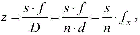

进一步地,所述图像由带有横纵两个方向长度信息,但其他相机参数未知的相机拍摄而成。Further, the image is captured by a camera with length information in horizontal and vertical directions, but other camera parameters are unknown.
进一步地,所述新图像即为所述图像的景物的俯视图。Further, the new image is a top view of the scene in the image.
进一步地,采用试凑法对透视变换后的所述图像中的某一物体进行调整。Further, a trial and error method is used to adjust an object in the image after perspective transformation.
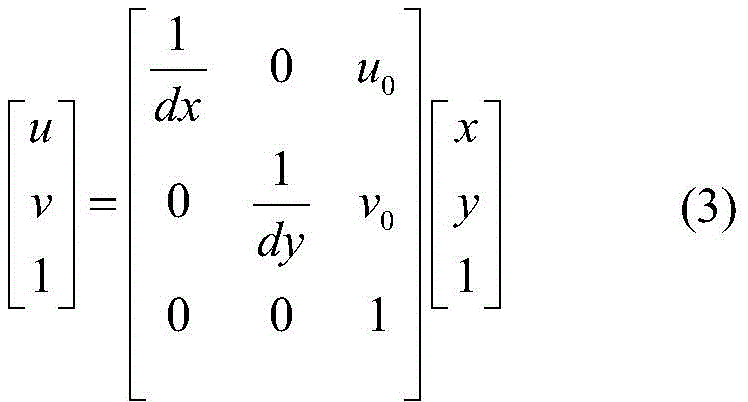
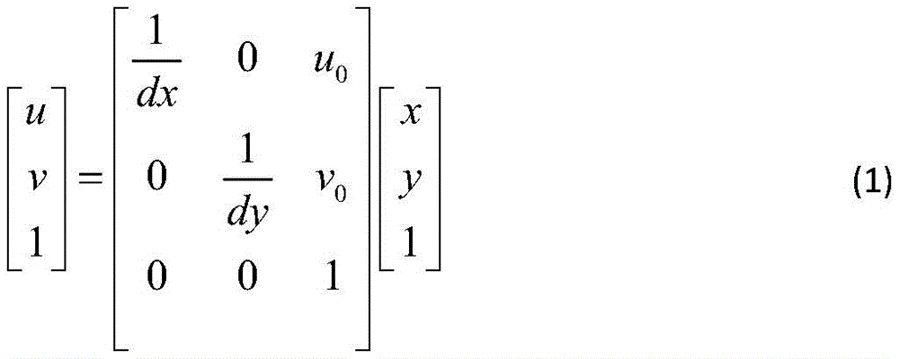
进一步地,像素坐标系以所述图像的左上角顶点为原点,以U轴和V轴为横纵轴,用(u,v)表示坐标,单位为像素;图像坐标系以所述图像的中心为原点,以x轴和y轴为横纵轴,x轴和y轴分别平行于U、V轴,用(x,y)表示坐标,单位为mm;相机坐标系则是以相机的光心为原点,以X轴和Y轴为横纵轴,X轴和Y轴分别平行于图像坐标系的x轴和y轴,相机的光轴为Z轴,图像坐标点P(x,y)对应相机坐标系的坐标点P(X,Y,Z);Further, the pixel coordinate system takes the upper left corner vertex of the image as the origin, the U axis and the V axis as the horizontal and vertical axes, and (u, v) to represent the coordinates, and the unit is pixel; the image coordinate system is based on the center of the image. The origin is the x-axis and the y-axis as the horizontal and vertical axes. The x-axis and the y-axis are parallel to the U and V axes respectively. The coordinates are represented by (x, y), and the unit is mm; the camera coordinate system is based on the optical center of the camera. As the origin, the X and Y axes are the horizontal and vertical axes, the X and Y axes are parallel to the x and y axes of the image coordinate system, the optical axis of the camera is the Z axis, and the image coordinate point P(x, y) corresponds to The coordinate point P(X, Y, Z) of the camera coordinate system;
像素坐标系与图像坐标系之间的关系如公式(1)所示:The relationship between the pixel coordinate system and the image coordinate system is shown in formula (1):

其中,dx和dy分别表示x轴和y轴中每个像素的尺寸,(u0,v0)表示图像坐标系的原点在像素坐标系中对应的坐标。Among them, dx and dy represent the size of each pixel in the x-axis and y-axis, respectively, and (u 0 , v 0 ) represent the coordinates corresponding to the origin of the image coordinate system in the pixel coordinate system.
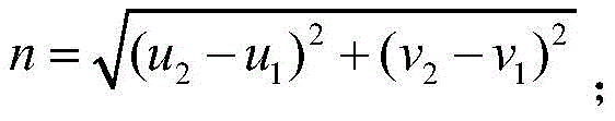
进一步地,在所述图像中选取一条直线EQ,E和Q点的在图像坐标系中的坐标分别为E(u1,v1)和Q(u2,v2),这两点在相机坐标系中对应的坐标分别是(X1,Y1,Z1)和(X2,Y2,Z2);由EQ两点间的像素个数n,结合单位像素的实际长度D,得到EQ两点的实际长度s,相机光心O'到直线EQ的深度为z,相机焦距为f,则D=d·n;其中d是像元尺寸,n为直线EQ的上像素个数,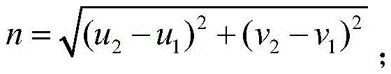
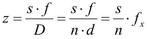
其中,
本发明提供的技术方案带来的有益效果是:在相机参数未知的情况下,简单明了的测量出拍摄者距离拍摄的图像中任一目标点的距离,且测量精度较高,具有实用性和适用性。The beneficial effects brought by the technical solution provided by the present invention are: in the case of unknown camera parameters, the distance between the photographer and any target point in the photographed image can be measured simply and clearly, and the measurement accuracy is high, which has practicality and practicability. applicability.
附图说明Description of drawings
下面将结合附图及实施例对本发明作进一步说明,附图中:The present invention will be further described below in conjunction with the accompanying drawings and embodiments, in which:
图1是本发明实施例中一种基于单目视觉模型和透视变换的图像测量方法的流程图;1 is a flowchart of an image measurement method based on a monocular vision model and perspective transformation in an embodiment of the present invention;
图2是本发明实施例中图像的示意图;2 is a schematic diagram of an image in an embodiment of the present invention;
图3是本发明实施例中透视变换原理的示意图;Fig. 3 is the schematic diagram of the perspective transformation principle in the embodiment of the present invention;
图4是本发明实施例中四点透视变换示意图;4 is a schematic diagram of four-point perspective transformation in an embodiment of the present invention;
图5是本发明实施例中透视变换前后的图像对比图;5 is an image comparison diagram before and after perspective transformation in the embodiment of the present invention;
图6是本发明实施例中相机单目视觉模型示意图;6 is a schematic diagram of a camera monocular vision model in an embodiment of the present invention;
图7是本发明实施例中图像坐标系和像素坐标系转换示意图;7 is a schematic diagram of the conversion between an image coordinate system and a pixel coordinate system in an embodiment of the present invention;
图8是本发明实施例中光心到目标直线距离求取示意图;8 is a schematic diagram of obtaining the linear distance from the optical center to the target in the embodiment of the present invention;
图9是本发明实施例中添加辅助线后的图像透视变换对比示意图;Fig. 9 is the image perspective transformation comparison schematic diagram after adding auxiliary line in the embodiment of the present invention;
图10是本发明实施例中平行线投影模型示意图。FIG. 10 is a schematic diagram of a parallel line projection model in an embodiment of the present invention.
具体实施方式Detailed ways
为了对本发明的技术特征、目的和效果有更加清楚的理解,现对照附图详细说明本发明的具体实施方式。In order to have a clearer understanding of the technical features, objects and effects of the present invention, the specific embodiments of the present invention will now be described in detail with reference to the accompanying drawings.
本发明的实施例提供了一种基于单目视觉模型和透视变换的图像测量方法。Embodiments of the present invention provide an image measurement method based on a monocular vision model and perspective transformation.
请参考图1~10,图1是本发明实施例中一种基于单目视觉模型和透视变换的图像测量方法的流程图,图2是本发明实施例中图像的示意图,图3是本发明实施例中透视变换原理的示意图,图4是本发明实施例中四点透视变换示意图,图5是本发明实施例中透视变换前后的图像对比图,图6是本发明实施例中相机单目视觉模型示意图,图7是本发明实施例中图像坐标系和像素坐标系转换示意图,图8是本发明实施例中光心到目标直线距离求取示意图,图9是本发明实施例中添加辅助线后的图像透视变换对比示意图,图10是本发明实施例中平行线投影模型示意图,具体包括如下步骤:Please refer to FIGS. 1 to 10. FIG. 1 is a flowchart of an image measurement method based on a monocular vision model and perspective transformation in an embodiment of the present invention, FIG. 2 is a schematic diagram of an image in an embodiment of the present invention, and FIG. 3 is the present invention. A schematic diagram of the perspective transformation principle in the embodiment, FIG. 4 is a schematic diagram of a four-point perspective transformation in an embodiment of the present invention, FIG. 5 is an image comparison diagram before and after perspective transformation in an embodiment of the present invention, and FIG. 6 is a camera monocular in an embodiment of the present invention. A schematic diagram of the visual model, FIG. 7 is a schematic diagram of the conversion of the image coordinate system and the pixel coordinate system in the embodiment of the present invention, FIG. 8 is a schematic diagram of the linear distance between the optical center and the target in the embodiment of the present invention, and FIG. 9 is an embodiment of the present invention. Figure 10 is a schematic diagram of a parallel line projection model in an embodiment of the present invention, which specifically includes the following steps:
S1:首先获取任一拍摄的图像;然后对该图像进行透视变换,并对透视变换后的图像的某一物体进行试凑法调整,使得透视变换及相应调整后得到的新图像中所述某一物体的纵横比与该物体的实际纵横比相同;同时根据所述新图像中任何已知实际距离,得到所述新图像中单位像素对应的实际距离D,以便计算所述新图像中任意两点之间的距离;所述图像由带有横纵两个方向长度信息,但其他相机参数未知的相机拍摄而成;所述新图像即为所述图像的景物的俯视图;S1: First acquire any captured image; then perform perspective transformation on the image, and perform trial-and-error adjustment on an object in the perspective-transformed image, so that a certain object in the new image obtained after the perspective transformation and corresponding adjustment is adjusted. The aspect ratio of an object is the same as the actual aspect ratio of the object; at the same time, according to any known actual distance in the new image, the actual distance D corresponding to the unit pixel in the new image is obtained, so as to calculate any two in the new image. The distance between points; the image is taken by a camera with length information in both horizontal and vertical directions, but other camera parameters are unknown; the new image is the top view of the scene in the image;
S2:以相机的光心为中心,建立像素坐标系、图像坐标系和相机坐标系,这3个坐标系彼此之间的转换关系即为建立的单目视觉模型,以所述新图像中任一固定长度的信息对单目视觉模型的坐标系间的点的转换参数fx进行求解;S2: Taking the optical center of the camera as the center, establish the pixel coordinate system, the image coordinate system and the camera coordinate system. The conversion relationship between these three coordinate systems is the established monocular vision model. A fixed-length information is used to solve the conversion parameter f x of the point between the coordinate systems of the monocular vision model;
S3:在所述图像上,构建两条辅助线RO和ST,这两条辅助线均平行于所述图像的底边,其中辅助直线RO穿过该图像的中心点O,辅助直线ST与辅助直线RO的距离为dis;对添加辅助线后的图像进行透视变换,构建基于两条辅助直线RO和ST的双平行线投影模型,得到辅助直线RO与直线SP的像素个数分别为n1和n2;P为拍摄者F到图像的正中心O的直线与直线ST的交点,则结合步骤S1中得到的单位像素对应的距离,即得到直线RO的实际距离s1与直线SP的实际距离s2;根据拍摄者X到两条直线RO与SP之间的距离差等于距离dis,求解得到单目视觉模型的坐标系间的点的转换参数fx;S3: On the image, construct two auxiliary lines RO and ST, both of which are parallel to the bottom edge of the image, wherein the auxiliary straight line RO passes through the center point O of the image, and the auxiliary straight line ST and the auxiliary line The distance of the straight line RO is dis; perform perspective transformation on the image after adding the auxiliary line, and construct a double-parallel line projection model based on the two auxiliary lines RO and ST, and obtain the number of pixels of the auxiliary line RO and the line SP are n 1 and 1 respectively. n 2 ; P is the intersection of the straight line from the photographer F to the center O of the image and the straight line ST, then in combination with the distance corresponding to the unit pixel obtained in step S1, the actual distance s 1 of the straight line RO and the actual distance of the straight line SP are obtained. s 2 ; according to the distance difference between the photographer X to the two straight lines RO and SP equal to the distance dis, solve the conversion parameter f x of the point between the coordinate systems of the monocular vision model;
S4:根据求解出的转换参数fx,根据公式

如图2所示为选取的所述图像,以求解拍摄者X距离马路左边的距离为例,进行本方法的具体操作的描述。The selected image is shown in FIG. 2 , and the specific operation of the method is described by taking the solution of the distance between the photographer X and the left side of the road as an example.
步骤一:对所述图像进行透视变换,得到地面的俯视图,并且作相应的标定Step 1: Perform perspective transformation on the image to obtain a top view of the ground, and perform corresponding calibration
透视变换的本质使将图像投影到一个新的视平面,体现为图像的“直线性”,即原图像里面的直线,经透视变换后仍为直线,如图3所示,在此实例中,主要使地面的转换,图像在二维平面,其转换后的图像如图4所示。变换后横纵两个方向物体的实际距离信息,通过透视变换,可以使画面正确的表现出物体之间的远近层次关系,也能使图像由原来的“近大远小”画面还原成横纵比与实际相同的图像,这也是透视变换的目的之一。The essence of perspective transformation is to project the image to a new viewing plane, which is reflected in the "straightness" of the image, that is, the straight line in the original image is still a straight line after perspective transformation, as shown in Figure 3. In this example, Mainly to transform the ground, the image is in a two-dimensional plane, and the transformed image is shown in Figure 4. After the transformation, the actual distance information of objects in the horizontal and vertical directions can be transformed into the picture to correctly show the distance between the objects. than the actual same image, which is also one of the purposes of perspective transformation.
对透视变换后的图像中确定长度和宽度的物体进行标定,分析计算出此平面每个像素点在横纵两个方向上对应的距离,也就可以计算此平面上任意两点的距离。透视变换的原理如下,原目标点为

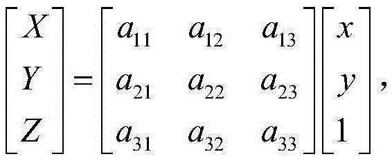

令a33=1,展开公式,可得:Let a 33 =1, expand the formula, we can get:

具体的透视变换如图5所示,首先根据做出与图像中视野开阔而且与道路中间间隔出现的双线垂直的两条辅助线线HI和JK,如图5的(a)图所示。使用试凑法来矫正图像,直到得到的新图像中某一参照物的横纵像素比与该参照物实际横纵比一致,比如可以选取图像中马路中实际的双黄虚线的长度和宽度,在实际道路中,马路上的路标都有相应的标准,在这里以它的信息为参考作为图像标定,最终得到如图5中的(b)图所示的矫正后的图像。The specific perspective transformation is shown in Figure 5. First, two auxiliary lines HI and JK, which are perpendicular to the double lines with a wide field of view in the image and appear at intervals in the middle of the road, are made, as shown in (a) of Figure 5. Use the trial and error method to correct the image until the aspect ratio of a reference object in the obtained new image is consistent with the actual aspect ratio of the reference object. For example, the length and width of the actual double yellow dotted line in the road in the image can be selected. In the actual road, the road signs on the road have corresponding standards. Here, its information is used as a reference for image calibration, and finally a corrected image as shown in (b) in Figure 5 is obtained.
得到矫正后的图像即可利用图中任何已知的长度信息来计算该平面的任两点或任意两条直线的距离,在图5中的(b)图中,根据栅栏间距等已知距离信息计算出单位像素与实际尺寸的比例信息,即单位像素对应的实际距离D,以此为基准做后续的计算。After the corrected image is obtained, any known length information in the figure can be used to calculate the distance between any two points or any two straight lines in the plane. The information calculates the ratio information of the unit pixel and the actual size, that is, the actual distance D corresponding to the unit pixel, and uses this as a benchmark for subsequent calculations.
步骤二:建立单目视觉系统模型,分析光心到点和直线的深度Step 2: Establish a monocular vision system model and analyze the depth of the optical center to the point and the line
基于普通图像求取相关的距离,首先建立如图6所示的单目视觉系统模型,以光心O'为中心建立现实世界的笛卡尔三维坐标系,然后选取图中的固定长度的信息对单目视觉模型参数进行反解,求得模型中的数据。要计算目标相对相机的三维坐标则涉及到三个坐标系:像素坐标系、图像坐标系(ICS)和相机坐标系(CCS)的转化。其中,像素坐标系以所述图像的左上角顶点为原点,以U轴和V轴为横纵轴,用(u,v)表示坐标,单位为像素;图像坐标系以所述图像的中心为原点,以x轴和y轴为横纵轴,x轴和y轴分别平行于U、V轴,用(x,y)表示坐标,单位为mm;相机坐标系则是以相机的光心为原点,以X轴和Y轴为横纵轴,X轴和Y轴分别平行于图像坐标系的x轴和y轴,相机的光轴为Z轴,图像坐标点P(x,y)对应相机坐标系的坐标点P(X,Y,Z);图像坐标系中的点(x,y)对应与实际空间坐标中的点(x,y,z)。To obtain the relevant distance based on ordinary images, first establish the monocular vision system model as shown in Figure 6, establish a real-world Cartesian three-dimensional coordinate system with the optical center O' as the center, and then select the fixed-length information pairs in the figure. The parameters of the monocular vision model are inversely solved to obtain the data in the model. To calculate the three-dimensional coordinates of the target relative to the camera, three coordinate systems are involved: the transformation of the pixel coordinate system, the image coordinate system (ICS), and the camera coordinate system (CCS). Among them, the pixel coordinate system takes the upper left corner of the image as the origin, the U axis and the V axis as the horizontal and vertical axes, and (u, v) represents the coordinates, and the unit is pixel; the image coordinate system takes the center of the image as the center The origin, with the x-axis and y-axis as the horizontal and vertical axes, the x-axis and the y-axis are parallel to the U and V axes respectively, and the coordinates are expressed by (x, y) in mm; the camera coordinate system is based on the optical center of the camera. The origin, with the X-axis and Y-axis as the horizontal and vertical axes, the X-axis and Y-axis are parallel to the x-axis and y-axis of the image coordinate system, the optical axis of the camera is the Z-axis, and the image coordinate point P(x, y) corresponds to the camera The coordinate point P (X, Y, Z) of the coordinate system; the point (x, y) in the image coordinate system corresponds to the point (x, y, z) in the actual space coordinate.
1)计算实际点的深度1) Calculate the depth of the actual point
根据如图6所示的单目视觉模型,建立如图7所示的图像坐标系和像素坐标系之间的联系,由图7可知,在ICS中,像素坐标系与图像坐标系之间的关系式如下所示,其中,dx和dy分别表示x轴和y轴中每个像素的尺寸,f是相机的焦距:According to the monocular vision model shown in Figure 6, the relationship between the image coordinate system and the pixel coordinate system as shown in Figure 7 is established. It can be seen from Figure 7 that in ICS, the relationship between the pixel coordinate system and the image coordinate system is The relationship is as follows, where dx and dy represent the dimensions of each pixel in the x- and y-axes, respectively, and f is the focal length of the camera:
相机坐标系(CCS)中的点P(X,Y,Z)对应于图像坐标中的点p(x,y),根据相似关系,可以得到如下数学关系:The point P(X,Y,Z) in the camera coordinate system (CCS) corresponds to the point p(x,y) in the image coordinates. According to the similarity relationship, the following mathematical relationship can be obtained:

2)计算光心到图像某直线的距离2) Calculate the distance from the optical center to a line in the image
求解光心到图像中某直线的距离即求解光心到目标直线的深度,如图8所示,其中O'为相机的光心,也即单目视觉系统的光心,在图像中选取一条直线,两端点分别为E(u1,v1),Q(u2,v2),它们两点在实际中的坐标的分别是(x1,y1,z1)和(x2,y2,z2)。当光心距离直线较远时,拍摄者到该线段EQ上任意一点的深度(即距离)被认为是相同的,即O'到EQ线段的任一点的深度认为不变。Solving the distance from the optical center to a straight line in the image is to solve the depth from the optical center to the target line, as shown in Figure 8, where O' is the optical center of the camera, that is, the optical center of the monocular vision system, select a line in the image Straight line, the two end points are E(u 1 , v 1 ), Q(u 2 , v 2 ), and the coordinates of their two points in reality are (x 1 , y 1 , z 1 ) and (x 2 , y 2 ,z 2 ). When the optical center is far away from the straight line, the depth (ie, the distance) from the photographer to any point on the line segment EQ is considered to be the same, that is, the depth from O' to any point on the EQ line segment is considered unchanged.
在图8中,EQ两点在实际中的长度为s,单位像素的实际长度为D,相机光心到直线的深度为z,焦距为f,则有D=d·n。其中d是像元尺寸,n为该直线上像素个数,可以得到:

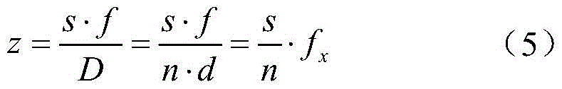
其中,fx是一个简化量,
步骤三:构建辅助线并作透视变换,得到平行投影模型,计算需要求取的距离Step 3: Build auxiliary lines and perform perspective transformation to obtain a parallel projection model, and calculate the distance to be obtained
步骤一中已经做了相应的透视变换,并且求得了变换后单个像素点对应的距离。在步骤三中,在所述图像中构建两条辅助线,然后进行透视变换,用于分析相关的模型,以求解拍摄者X距离马路左边的距离的例子为引导,进行如下步骤:In
1)在如图9中的(a)图所示的图像中,构建两条平行于该图像底边的辅助直线,要求其中一条是经过该图像正中心,因为这样的角度是从光心出发并且垂直于ICS。如图9中的(a)图所示的直线RO和直线ST,经过透视变换后得到的图像如图9中的(b)图所示。1) In the image shown in (a) of Figure 9, construct two auxiliary straight lines parallel to the bottom edge of the image, and one of them is required to pass through the center of the image, because such an angle starts from the optical center And perpendicular to the ICS. For the straight line RO and the straight line ST shown in (a) of FIG. 9 , the image obtained after perspective transformation is shown in (b) of FIG. 9 .
2)构建双平行线投影模型。辅助线在经过透视变换之后,其俯视的示意图如图10所示,由图像可以直接得出线段SP和SP的像素点个数n1和n2。由于RO是经过图像正中心且平行于底边的直线,因此从拍摄者出发到正中心点O的直线XO与之垂直,同理SP也与XO垂直。由于新图像中单位像素表示的实际距离已知,可以计算出线段RO和SP的实际距离分别为s1和s2。2) Build a double parallel line projection model. After the auxiliary line undergoes perspective transformation, a schematic top view of the auxiliary line is shown in FIG. 10 , and the number of pixels n 1 and n 2 of the line segments SP and SP can be directly obtained from the image. Since RO is a straight line passing through the center of the image and parallel to the bottom edge, the straight line XO from the photographer to the center point O is perpendicular to it, and SP is also perpendicular to XO. Since the actual distance represented by the unit pixel in the new image is known, the actual distances of the line segments RO and SP can be calculated as s 1 and s 2 , respectively.
3)由公式(4)可得拍摄者X到两条直线RO和SP的深度分别为


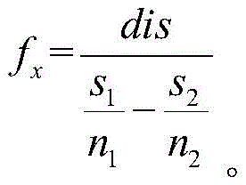
4)由步骤3)中得到的fx的值求取光心到直线RO的深度
通过本发明中所述的基于单目视觉模型和透视变换的图像测量方法,即可简单快速的求出拍摄者距离拍摄的图像中任一目标点的距离,且精度较高。Through the image measurement method based on the monocular vision model and perspective transformation described in the present invention, the distance between the photographer and any target point in the captured image can be simply and quickly obtained with high accuracy.
本发明的有益效果是:在相机参数未知的情况下,简单明了的测量出拍摄者距离拍摄的图像中任一目标点的距离,且测量精度较高,具有实用性和适用性。The beneficial effects of the present invention are: in the case of unknown camera parameters, the distance between the photographer and any target point in the captured image can be measured simply and clearly, and the measurement accuracy is high, and it has practicability and applicability.
以上所述仅为本发明的较佳实施例,并不用以限制本发明,凡在本发明的精神和原则之内,所作的任何修改、等同替换、改进等,均应包含在本发明的保护范围之内。The above are only preferred embodiments of the present invention and are not intended to limit the present invention. Any modifications, equivalent replacements, improvements, etc. made within the spirit and principles of the present invention shall be included in the protection of the present invention. within the range.
Claims (6)


Priority Applications (1)
| Application Number | Priority Date | Filing Date | Title |
|---|---|---|---|
| CN201911236558.9A CN111192235B (en) | 2019-12-05 | 2019-12-05 | Image measurement method based on monocular vision model and perspective transformation |
Applications Claiming Priority (1)
| Application Number | Priority Date | Filing Date | Title |
|---|---|---|---|
| CN201911236558.9A CN111192235B (en) | 2019-12-05 | 2019-12-05 | Image measurement method based on monocular vision model and perspective transformation |
Publications (2)
| Publication Number | Publication Date |
|---|---|
| CN111192235A true CN111192235A (en) | 2020-05-22 |
| CN111192235B CN111192235B (en) | 2023-05-26 |
Family
ID=70707534
Family Applications (1)
| Application Number | Title | Priority Date | Filing Date |
|---|---|---|---|
| CN201911236558.9A Active CN111192235B (en) | 2019-12-05 | 2019-12-05 | Image measurement method based on monocular vision model and perspective transformation |
Country Status (1)
| Country | Link |
|---|---|
| CN (1) | CN111192235B (en) |
Cited By (11)
| Publication number | Priority date | Publication date | Assignee | Title |
|---|---|---|---|---|
| CN111380503A (en) * | 2020-05-29 | 2020-07-07 | 电子科技大学 | Monocular camera ranging method adopting laser-assisted calibration |
| CN112197708A (en) * | 2020-08-31 | 2021-01-08 | 深圳市慧鲤科技有限公司 | Measuring method and device, electronic device and storage medium |
| CN112325780A (en) * | 2020-10-29 | 2021-02-05 | 青岛聚好联科技有限公司 | Distance measuring and calculating method and device based on community monitoring |
| CN112665577A (en) * | 2020-12-29 | 2021-04-16 | 北京电子工程总体研究所 | Monocular vision target positioning method and system based on inverse perspective transformation matrix |
| CN112734832A (en) * | 2021-01-22 | 2021-04-30 | 逆可网络科技有限公司 | Method for measuring real size of on-line object in real time |
| CN113124820A (en) * | 2021-06-17 | 2021-07-16 | 中国空气动力研究与发展中心低速空气动力研究所 | Monocular distance measurement method based on curved mirror |
| CN113361507A (en) * | 2021-08-11 | 2021-09-07 | 金成技术有限公司 | Visual measurement method for production information of structural member |
| CN113538578A (en) * | 2021-06-22 | 2021-10-22 | 恒睿(重庆)人工智能技术研究院有限公司 | Target positioning method and device, computer equipment and storage medium |
| CN114494393A (en) * | 2022-01-25 | 2022-05-13 | 阿里巴巴(中国)有限公司 | Monocular camera-based space measurement method, monocular camera-based space measurement device, monocular camera-based space measurement equipment and storage medium |
| CN114935316A (en) * | 2022-05-20 | 2022-08-23 | 长春理工大学 | Standard depth image generation method based on optical tracking and monocular vision |
| CN115588048A (en) * | 2022-10-25 | 2023-01-10 | 澳克诺(上海)汽车科技有限公司 | Target ranging method, device, electronic equipment and computer readable storage medium |
Citations (9)
| Publication number | Priority date | Publication date | Assignee | Title |
|---|---|---|---|---|
| JP2010157910A (en) * | 2008-12-26 | 2010-07-15 | Toyota Motor Corp | Image display device |
| WO2017076928A1 (en) * | 2015-11-02 | 2017-05-11 | Starship Technologies Oü | Method, device and assembly for map generation |
| CN109035320A (en) * | 2018-08-12 | 2018-12-18 | 浙江农林大学 | Depth extraction method based on monocular vision |
| CN109146980A (en) * | 2018-08-12 | 2019-01-04 | 浙江农林大学 | The depth extraction and passive ranging method of optimization based on monocular vision |
| CN109822754A (en) * | 2019-02-25 | 2019-05-31 | 长安大学 | System and method for size detection of dump truck cargo box for asphalt concrete mixing plant |
| CN110009682A (en) * | 2019-03-29 | 2019-07-12 | 北京理工大学 | A kind of object recognition and detection method based on monocular vision |
| CN110057295A (en) * | 2019-04-08 | 2019-07-26 | 河海大学 | It is a kind of to exempt from the monocular vision plan range measurement method as control |
| CN110136211A (en) * | 2019-04-18 | 2019-08-16 | 中国地质大学(武汉) | A workpiece positioning method and system based on active binocular vision technology |
| CN110174088A (en) * | 2019-04-30 | 2019-08-27 | 上海海事大学 | A kind of target ranging method based on monocular vision |
-
2019
- 2019-12-05 CN CN201911236558.9A patent/CN111192235B/en active Active
Patent Citations (9)
| Publication number | Priority date | Publication date | Assignee | Title |
|---|---|---|---|---|
| JP2010157910A (en) * | 2008-12-26 | 2010-07-15 | Toyota Motor Corp | Image display device |
| WO2017076928A1 (en) * | 2015-11-02 | 2017-05-11 | Starship Technologies Oü | Method, device and assembly for map generation |
| CN109035320A (en) * | 2018-08-12 | 2018-12-18 | 浙江农林大学 | Depth extraction method based on monocular vision |
| CN109146980A (en) * | 2018-08-12 | 2019-01-04 | 浙江农林大学 | The depth extraction and passive ranging method of optimization based on monocular vision |
| CN109822754A (en) * | 2019-02-25 | 2019-05-31 | 长安大学 | System and method for size detection of dump truck cargo box for asphalt concrete mixing plant |
| CN110009682A (en) * | 2019-03-29 | 2019-07-12 | 北京理工大学 | A kind of object recognition and detection method based on monocular vision |
| CN110057295A (en) * | 2019-04-08 | 2019-07-26 | 河海大学 | It is a kind of to exempt from the monocular vision plan range measurement method as control |
| CN110136211A (en) * | 2019-04-18 | 2019-08-16 | 中国地质大学(武汉) | A workpiece positioning method and system based on active binocular vision technology |
| CN110174088A (en) * | 2019-04-30 | 2019-08-27 | 上海海事大学 | A kind of target ranging method based on monocular vision |
Non-Patent Citations (3)
| Title |
|---|
| CAI MENG等: "Monocular pose measurement method based on circle and line features" * |
| M. N. A. WAHAB等: "Target Distance Estimation Using Monocular Vision System for Mobile Robot" * |
| 贾星伟等: "单目摄像机线性模型可靠性分析与研究" * |
Cited By (12)
| Publication number | Priority date | Publication date | Assignee | Title |
|---|---|---|---|---|
| CN111380503A (en) * | 2020-05-29 | 2020-07-07 | 电子科技大学 | Monocular camera ranging method adopting laser-assisted calibration |
| CN112197708A (en) * | 2020-08-31 | 2021-01-08 | 深圳市慧鲤科技有限公司 | Measuring method and device, electronic device and storage medium |
| CN112325780A (en) * | 2020-10-29 | 2021-02-05 | 青岛聚好联科技有限公司 | Distance measuring and calculating method and device based on community monitoring |
| CN112665577A (en) * | 2020-12-29 | 2021-04-16 | 北京电子工程总体研究所 | Monocular vision target positioning method and system based on inverse perspective transformation matrix |
| CN112734832A (en) * | 2021-01-22 | 2021-04-30 | 逆可网络科技有限公司 | Method for measuring real size of on-line object in real time |
| CN112734832B (en) * | 2021-01-22 | 2024-05-31 | 逆可网络科技有限公司 | Method for measuring real size of on-line object in real time |
| CN113124820A (en) * | 2021-06-17 | 2021-07-16 | 中国空气动力研究与发展中心低速空气动力研究所 | Monocular distance measurement method based on curved mirror |
| CN113538578A (en) * | 2021-06-22 | 2021-10-22 | 恒睿(重庆)人工智能技术研究院有限公司 | Target positioning method and device, computer equipment and storage medium |
| CN113361507A (en) * | 2021-08-11 | 2021-09-07 | 金成技术有限公司 | Visual measurement method for production information of structural member |
| CN114494393A (en) * | 2022-01-25 | 2022-05-13 | 阿里巴巴(中国)有限公司 | Monocular camera-based space measurement method, monocular camera-based space measurement device, monocular camera-based space measurement equipment and storage medium |
| CN114935316A (en) * | 2022-05-20 | 2022-08-23 | 长春理工大学 | Standard depth image generation method based on optical tracking and monocular vision |
| CN115588048A (en) * | 2022-10-25 | 2023-01-10 | 澳克诺(上海)汽车科技有限公司 | Target ranging method, device, electronic equipment and computer readable storage medium |
Also Published As
| Publication number | Publication date |
|---|---|
| CN111192235B (en) | 2023-05-26 |
Similar Documents
| Publication | Publication Date | Title |
|---|---|---|
| CN111192235B (en) | Image measurement method based on monocular vision model and perspective transformation | |
| CN109035320B (en) | Monocular vision-based depth extraction method | |
| CN109146980B (en) | Monocular vision based optimized depth extraction and passive distance measurement method | |
| CN103292710B (en) | A kind of distance measurement method applying binocular vision vision range finding principle | |
| CN110057295B (en) | Monocular vision plane distance measuring method without image control | |
| CN106408556B (en) | A Calibration Method for Small Object Measurement System Based on General Imaging Model | |
| CN110809786B (en) | Calibration device, calibration chart, chart pattern generating device and calibration method | |
| US10373337B2 (en) | Methods and computer program products for calibrating stereo imaging systems by using a planar mirror | |
| CN109238235B (en) | A method for continuous measurement of rigid body pose parameters based on monocular image sequences | |
| US20240394899A1 (en) | Method, Apparatus and Device for Photogrammetry, and Storage Medium | |
| CN110146030A (en) | Slope Surface Deformation Monitoring System and Method Based on Checkerboard Marking Method | |
| CN107680139B (en) | Universality calibration method of telecentric binocular stereo vision measurement system | |
| KR102129206B1 (en) | 3 Dimensional Coordinates Calculating Apparatus and 3 Dimensional Coordinates Calculating Method Using Photo Images | |
| CN109255818B (en) | A novel target and its sub-pixel corner extraction method | |
| Liu et al. | Epipolar rectification method for a stereovision system with telecentric cameras | |
| CN113870365B (en) | Camera calibration method, device, equipment and storage medium | |
| CN103473758A (en) | Secondary calibration method of binocular stereo vision system | |
| CN112950727B (en) | Simultaneous ranging method for multiple targets with large field of view based on bionic surface compound eye | |
| CN107545586A (en) | Based on the local depth acquisition methods of light field limit plane picture and system | |
| CN104504691B (en) | Camera position and posture measuring method on basis of low-rank textures | |
| CN113706635B (en) | Long-focus camera calibration method based on point feature and line feature fusion | |
| CN116952191A (en) | Visual ranging method based on coaxial photography | |
| CN105335959A (en) | Quick focusing method and device for imaging apparatus | |
| CN110470216B (en) | Three-lens high-precision vision measurement method and device | |
| CN108413941A (en) | A kind of simple and efficient distance measuring method based on cheap binocular camera |
Legal Events
| Date | Code | Title | Description |
|---|---|---|---|
| PB01 | Publication | ||
| PB01 | Publication | ||
| SE01 | Entry into force of request for substantive examination | ||
| SE01 | Entry into force of request for substantive examination | ||
| GR01 | Patent grant | ||
| GR01 | Patent grant |