CN111076721B - Fast-convergence inertial measurement unit installation attitude estimation method - Google Patents
Fast-convergence inertial measurement unit installation attitude estimation method Download PDFInfo
- Publication number
- CN111076721B CN111076721B CN202010062352.5A CN202010062352A CN111076721B CN 111076721 B CN111076721 B CN 111076721B CN 202010062352 A CN202010062352 A CN 202010062352A CN 111076721 B CN111076721 B CN 111076721B
- Authority
- CN
- China
- Prior art keywords
- kalman filter
- measurement unit
- matrix
- installation attitude
- angle
- Prior art date
- Legal status (The legal status is an assumption and is not a legal conclusion. Google has not performed a legal analysis and makes no representation as to the accuracy of the status listed.)
- Active
Links
- 238000005259 measurement Methods 0.000 title claims abstract description 50
- 238000009434 installation Methods 0.000 title claims abstract description 43
- 238000000034 method Methods 0.000 title claims abstract description 35
- 239000002245 particle Substances 0.000 claims abstract description 29
- 239000011159 matrix material Substances 0.000 claims description 48
- 239000013598 vector Substances 0.000 claims description 32
- 238000012804 iterative process Methods 0.000 claims description 10
- 230000007704 transition Effects 0.000 claims description 10
- 238000011156 evaluation Methods 0.000 claims description 3
- 230000001133 acceleration Effects 0.000 claims description 2
- 238000001914 filtration Methods 0.000 claims description 2
- 230000007547 defect Effects 0.000 description 1
- 230000000694 effects Effects 0.000 description 1
- 238000002474 experimental method Methods 0.000 description 1
- 230000005484 gravity Effects 0.000 description 1
- 238000012986 modification Methods 0.000 description 1
- 230000004048 modification Effects 0.000 description 1
- 238000012545 processing Methods 0.000 description 1
Images


Classifications
-
- G—PHYSICS
- G01—MEASURING; TESTING
- G01C—MEASURING DISTANCES, LEVELS OR BEARINGS; SURVEYING; NAVIGATION; GYROSCOPIC INSTRUMENTS; PHOTOGRAMMETRY OR VIDEOGRAMMETRY
- G01C21/00—Navigation; Navigational instruments not provided for in groups G01C1/00 - G01C19/00
- G01C21/10—Navigation; Navigational instruments not provided for in groups G01C1/00 - G01C19/00 by using measurements of speed or acceleration
- G01C21/12—Navigation; Navigational instruments not provided for in groups G01C1/00 - G01C19/00 by using measurements of speed or acceleration executed aboard the object being navigated; Dead reckoning
- G01C21/16—Navigation; Navigational instruments not provided for in groups G01C1/00 - G01C19/00 by using measurements of speed or acceleration executed aboard the object being navigated; Dead reckoning by integrating acceleration or speed, i.e. inertial navigation
- G01C21/165—Navigation; Navigational instruments not provided for in groups G01C1/00 - G01C19/00 by using measurements of speed or acceleration executed aboard the object being navigated; Dead reckoning by integrating acceleration or speed, i.e. inertial navigation combined with non-inertial navigation instruments
-
- G—PHYSICS
- G01—MEASURING; TESTING
- G01C—MEASURING DISTANCES, LEVELS OR BEARINGS; SURVEYING; NAVIGATION; GYROSCOPIC INSTRUMENTS; PHOTOGRAMMETRY OR VIDEOGRAMMETRY
- G01C21/00—Navigation; Navigational instruments not provided for in groups G01C1/00 - G01C19/00
- G01C21/10—Navigation; Navigational instruments not provided for in groups G01C1/00 - G01C19/00 by using measurements of speed or acceleration
- G01C21/12—Navigation; Navigational instruments not provided for in groups G01C1/00 - G01C19/00 by using measurements of speed or acceleration executed aboard the object being navigated; Dead reckoning
- G01C21/16—Navigation; Navigational instruments not provided for in groups G01C1/00 - G01C19/00 by using measurements of speed or acceleration executed aboard the object being navigated; Dead reckoning by integrating acceleration or speed, i.e. inertial navigation
- G01C21/18—Stabilised platforms, e.g. by gyroscope
-
- G—PHYSICS
- G01—MEASURING; TESTING
- G01S—RADIO DIRECTION-FINDING; RADIO NAVIGATION; DETERMINING DISTANCE OR VELOCITY BY USE OF RADIO WAVES; LOCATING OR PRESENCE-DETECTING BY USE OF THE REFLECTION OR RERADIATION OF RADIO WAVES; ANALOGOUS ARRANGEMENTS USING OTHER WAVES
- G01S19/00—Satellite radio beacon positioning systems; Determining position, velocity or attitude using signals transmitted by such systems
- G01S19/38—Determining a navigation solution using signals transmitted by a satellite radio beacon positioning system
- G01S19/39—Determining a navigation solution using signals transmitted by a satellite radio beacon positioning system the satellite radio beacon positioning system transmitting time-stamped messages, e.g. GPS [Global Positioning System], GLONASS [Global Orbiting Navigation Satellite System] or GALILEO
- G01S19/42—Determining position
- G01S19/48—Determining position by combining or switching between position solutions derived from the satellite radio beacon positioning system and position solutions derived from a further system
- G01S19/49—Determining position by combining or switching between position solutions derived from the satellite radio beacon positioning system and position solutions derived from a further system whereby the further system is an inertial position system, e.g. loosely-coupled
Landscapes
- Engineering & Computer Science (AREA)
- Radar, Positioning & Navigation (AREA)
- Remote Sensing (AREA)
- Physics & Mathematics (AREA)
- General Physics & Mathematics (AREA)
- Automation & Control Theory (AREA)
- Computer Networks & Wireless Communication (AREA)
- Navigation (AREA)
Abstract
The invention discloses a fast-convergence inertial measurement unit installation attitude estimation method, and relates to the technical field of inertial navigation/satellite navigation combination navigation. The invention decomposes the installation attitude angle of the vehicle-mounted low-cost consumption-level inertia measurement unit into a large-angle prior installation attitude angle and a small-angle misalignment angle, adopts the particle filter to estimate the large-angle prior installation attitude angle, and simultaneously adopts the Kalman filter to estimate the small-angle misalignment angle. By implementing the method, the high-precision estimation of the installation attitude angle of the inertial measurement unit can be completed, and the convergence time is short; the problems that the installation attitude angle is limited to be a small angle or the convergence time is long in the existing method are solved; the invention can obviously improve the navigation precision when being applied to the integrated navigation system, and has higher practical value and considerable economic benefit.
Description
Technical Field
The invention belongs to the technical field of inertial navigation/satellite navigation combined navigation, and particularly relates to a method for estimating the installation attitude of a rapidly-converged inertial measurement unit.
Background
For a vehicle-mounted inertial navigation/satellite navigation combined navigation system adopting a low-cost consumer-grade inertial measurement unit, when a satellite navigation signal is weak or interrupted, an error of navigation calculation is rapidly increased. The system is assisted by vehicle incomplete constraint (the lateral and vertical speed components of the vehicle are 0 in normal running), and the navigation resolving error can be corrected in real time when the satellite navigation signal is weak or interrupted, so that the problem that the navigation resolving error is rapidly increased in the scene is effectively solved. The mounting attitude information of the inertial measurement unit with respect to the vehicle is a necessary condition for correctly applying the vehicle incomplete constraint, but in practical application, the mounting attitude angle cannot be accurately determined, and some estimation method must be adopted to acquire the value of the mounting attitude angle. Most of the methods mentioned in the existing documents have limitations, for example, the papers of VINANDE et al propose a method for estimating the installation attitude of an inertial measurement unit by using accelerometer data, but the method has large error and slow convergence time (several minutes) when applied to a low-cost consumer-grade inertial measurement unit; for another example, a method for estimating the installation attitude of the inertial measurement unit based on the kalman filter is also proposed in the WU et al, but the method limits the installation attitude angle to a small angle, and in practical applications, such a requirement may not be met.
Therefore, those skilled in the art are dedicated to develop a fast converging method for estimating the installation attitude of the inertial measurement unit, so as to achieve the purpose of improving the estimation accuracy of the installation attitude angle of the inertial measurement unit.
Disclosure of Invention
In view of the above-mentioned defects of the prior art, the technical problem to be solved by the present invention is how to solve the problems that the vehicle-mounted low-cost consumer-grade inertial measurement unit cannot accurately estimate the installation attitude angle and the convergence time is long.
In order to achieve the purpose, the invention discloses a method for estimating the installation attitude of a rapidly-converged inertial measurement unit, which relates to the technical field of inertial navigation satellite navigation combination navigation and comprises the following steps:
symbol convention: psi βα Representing the euler angle (attitude angle) from the beta coordinate system to the alpha coordinate system, a rotation matrix representing a beta coordinate system to an alpha coordinate system; i represents an inertial coordinate system, e represents a geocentric geostationary coordinate system, b represents an inertial measurement unit coordinate system (the origin is positioned at the center of the inertial measurement unit, and the coordinate axes are coincident with three sensitive axes of the inertial measurement unit), and b 0 Representing a priori inertial measurementsA unit coordinate system (a coordinate system which has a small Euler angle difference with the inertial measurement unit coordinate system), v represents a vehicle body coordinate system (the origin is positioned at the center of a rear wheel of the vehicle, the x axis points to the right front of the vehicle, the y axis points to the right of the vehicle, and the z axis points to the right lower part of the vehicle), and a represents a GNSS antenna coordinate system (the origin is positioned at the phase center of the GNSS antenna);
 An evaluation value representing the quantity x>
 Representing the measured value of the quantity x.
Step one, setting the number of particles N and the termination threshold value N 0 ;
Step two, initializing particle swarm And a weight sequence>
 Status vector for each particle>
 Uniformly taken from the installation attitude angle, weight w, of the inertial measurement unit in its possible installation space j Taking the weights as equal: w is a j =1/N;/>
Step three, placing a loop variable k ← 1, wherein the loop variable represents the iteration moment of the combined navigation Kalman filter;
step four, using the state vector (prior installation attitude angle) corresponding to each particle ) Generating N different instances of Kalman filters as parameters of the integrated navigation Kalman filter, and then operating the N instances simultaneously;
step five, reading the state vector estimated value of each instance at the moment k, and calculating each instance pair according to the following formulaEstimated value of corresponding GNSS antenna speed

Right side of the above formula { · } j [k]Indicating that each estimation quantity in parentheses is used for measuring the value of the jth Kalman filter instance at the moment k, for the angular speed measurement of the gyroscope at instant k>
 For the jth Kalman filter parameter
 Calculating a prior rotation matrix;
step six, reading the GNSS antenna speed measurement value at the moment k And its accuracy sigma v [k];
Step seven, updating the weight of each particle according to the following formula:

and normalizing:
w j ←Aw j ,j=1,2,…,N;
wherein

Step eight, calculating the effective particle number according to the following formula:

if the effective particle number is less than N 0 Step nine, otherwise, placing k ← k +1, and then step five;
nine steps are (find the number of the particle with the largest weight);
step ten, get the j m Of the state vector of the Kalman filter instance at time k Sub-evaluation value>
 According to the Euler angle psi βα =[φ,θ,ψ] T To the rotation matrix->
 The calculation formula of (2):

calculating a corresponding rotation matrix:

then from the j (th) position m The state vector of each particle Calculating a corresponding rotation matrix: />

And finally, calculating a rotation matrix estimation value of the v coordinate system relative to the b coordinate system:

eleven, according to the rotation matrix To Euler angle>
 The calculation formula of (2):

calculating Euler angles of v system relative to b system:

this attitude angle is the estimated value of the installation attitude angle of the inertial measurement unit.
Further, the structure and the iteration process of the integrated navigation kalman filter in the fourth step further include: according to the state transition matrix, the observation matrix, the state transition noise matrix and the observation noise matrix, iteration is carried out according to a standard Kalman filtering process:
and (3) prediction:

propagation of error covariance matrix:
P - [k]=Φ[k-1]P[k-1]Φ[k-1] T +Q;
kalman gain matrix:
K[k]=P - [k]H[k] T (H[k]P - [k]H[k] T +R[k]) -1 ;
and the state vector is corrected:

and correcting the error covariance matrix:
P[k]=(I-K[k]H[k])P - [k]。
further, the structure and the iteration process of the integrated navigation kalman filter in the fourth step further include: the Kalman filter is set at the given prior installation attitude angle As a parameter, the prior rotation matrix ≥ is calculated from the prior installation attitude angle by the following formula>
 And &>

Further, the structure and the iteration process of the integrated navigation kalman filter in the fourth step further include: taking the position, speed and attitude error of the origin of the b coordinate system (all relative to the geocentric geostationary coordinate system), zero offset and misalignment angle of the gyroscope and the accelerometer The lever arms of a to b series and v to b series (both projected to v series) constitute the 24-dimensional state vector: />

Further, in the fourth step, the integrated navigation kalman filter, the structure and the iterative process further include: taking the position, the speed and the two-dimensional zero vector n = [0,0 ] of the GNSS antenna phase center] T And forming an 8-dimensional observation vector:

further, the structure and the iteration process of the integrated navigation kalman filter in the fourth step further include: the last 3 components of the state vector x have a state transition model of:

the iteration time interval is τ, and the state transition matrix of the kalman filter is:

wherein,


subscript k represents the value of each measured value and estimated value in the formula at the time k; represents the speed of the rotation angle of the earth>
 Specific force measurements representing accelerometers [ ·] × The anti-symmetric matrix corresponding to the vector in the square bracket is shown;
 In order to accelerate the gravity,
 represents latitude->
 The surface geocentric radius of the reference ellipsoid at (a).
Further, in the fourth step, the integrated navigation kalman filter, the structure and the iterative process further include:
the observation model of the GNSS antenna phase center position is as follows:

the observation model of the phase center velocity of the GNSS antenna is:

the observation model for a two-dimensional zero vector n is:

the observation matrix of the Kalman filter is:

wherein,


the index k indicates that the measured and estimated values in the equation take the value at time k.
Further, the structure and the iteration process of the integrated navigation kalman filter in the fourth step further include: the state vector is initialized to a full zero vector The error covariance matrix is initialized to a diagonal matrix:

where Δ x represents the initial uncertainty of the quantity x.
Further, the structure and the iteration process of the integrated navigation kalman filter in the fourth step further include: is provided with S rg ,S ra ,S bgd ,S bad Respectively a gyroscope random noise PSD, an accelerometer random noise PSD, a gyroscope zero bias change PSD and an accelerometer zero bias change PSD, wherein the state transition noise matrix is as follows:

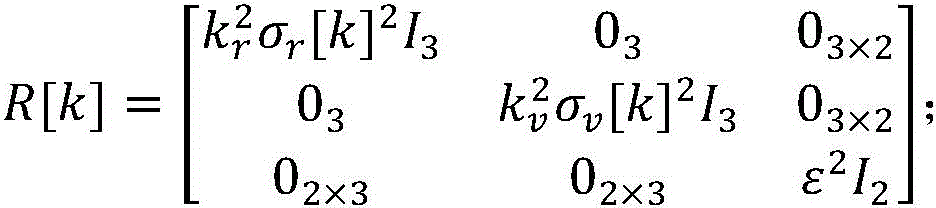
GNSSThe position and velocity accuracy of the device output at time k are respectively sigma r [k],σ v [k]The standard deviation of the motion constrained virtual observation noise is epsilon, and the covariance matrix of the observation noise is as follows:

wherein k is r And k v Are two empirical parameters greater than 1.
Compared with the prior art, the implementation of the invention achieves the following obvious technical effects:
1. the method can accurately estimate the installation attitude angle of the vehicle-mounted low-cost consumer-grade inertia measurement unit, and can quickly converge, the error of the attitude angle is less than 2.5 degrees, and the convergence time is less than one minute.
2. According to the invention, the installation attitude of the inertial measurement unit is not required to be limited, and the installation attitude angle can be accurately estimated by using the method when the inertial measurement unit is installed on the vehicle body in any attitude, so that a sufficient guarantee is provided for the application of vehicle incomplete constraint assistance.
3. The method has important value for improving the precision of the low-cost consumer-grade vehicle-mounted inertial navigation/satellite navigation integrated navigation system.
Drawings
FIG. 1 is a flow chart of a preferred embodiment of the present invention;
FIG. 2 is a schematic view of the installation of an inertial measurement unit in accordance with a preferred embodiment of the present invention;
fig. 3 is a particle swarm weight distribution graph iterated until k =43 in a preferred embodiment of the invention.
Wherein: 1-GNSS antenna, 2-inertial measurement unit, 3-vehicle.
Detailed Description
The technical contents of the preferred embodiments of the present invention will be made clear and easily understood by referring to the drawings attached to the specification. The present invention may be embodied in many different forms of embodiments and the scope of the invention is not limited to the embodiments set forth herein.
In the drawings, structurally identical elements are represented by like reference numerals, and structurally or functionally similar elements are represented by like reference numerals throughout the several views. The size and thickness of each component shown in the drawings are arbitrarily illustrated, and the present invention is not limited to the size and thickness of each component. The thickness of the components may be exaggerated where appropriate in the figures to improve clarity. In order to ensure clarity and conciseness of the attached images, some devices are not shown in the drawings, but do not affect the understanding of the invention by those of ordinary skill in the relevant art.
Example 1:
as shown in fig. 2, a GNSS antenna 1 and an inertial measurement unit 2 are installed at the top level of a vehicle 3, the GNSS antenna 1 is used for receiving GNSS navigation signals, the inertial measurement unit 2 is used for measuring angular velocity and acceleration, and navigation and measurement data are sent to a processor for processing.
As shown in fig. 1, the present embodiment provides a method for estimating a mounting attitude of a fast converging inertial measurement unit, where the flowchart includes the following steps:
step one, setting the number of particles N =72 and a termination threshold N 0 =60。
Step two, initializing particle swarm And a weight sequence>
 The state vector for each particle may be taken to be->
 Weight w j Taken as equal weight: w is a j =1/72。
And step three, setting a loop variable k ← 1, wherein the loop variable represents the iteration time of the combined navigation Kalman filter.
Step four, using the state vector (prior installation attitude angle) corresponding to each particle ) As parameters for the integrated navigation kalman filter, 72 different instances of the kalman filter are generated, each with an iteration time interval of 1 second, and then these 72 instances are run simultaneously.
Step five, reading the state vector estimated value of each instance at the moment k, and calculating the estimated value of the GNSS antenna speed corresponding to each instance according to the following formula

Right side of the above formula { · } j [k]It is shown that each estimate in brackets takes the value of the jth kalman filter instance at time k, is the angular velocity measurement of the gyroscope at time k, <' > is>
 Is based on the jth Kalman filter parameter->
 And calculating the obtained prior rotation matrix.
Step six, reading GNSS speed measurement value at the moment k And its accuracy sigma v [k]。/>
Step seven, updating the weight of each particle according to the following formula:

and normalizing:
w j ←Aw j ,j=1,2,…,72;
wherein

Step eight, calculating the effective particle number according to the following formula:

if the number of effective particles is less than N 0 Go to step nine, otherwise, place k ← k +1, then go to step five.
Step nine, as shown in fig. 3, the weight of each particle when the convergence occurs for 43 seconds in this embodiment. The largest weighted particle has a number j m =54。
Step ten, get the j m Of state vectors of instances of Kalman filters at time k Component estimation value
 According to the Euler angle psi βα =[φ,θ,ψ] T To the rotation matrix
 The calculation formula of (2):

calculating a corresponding rotation matrix:

then from the j (th) position m State vector of individual particle Calculating a corresponding rotation matrix:

and finally, calculating a rotation matrix estimation value of the v coordinate system relative to the b coordinate system, wherein the result is as follows:

eleven step of obtaining a rotation matrix To Euler angle->
 The calculation formula of (c):

calculating Euler angles of v system relative to b system:

the attitude angle is an estimated value of the installation attitude angle of the inertial measurement unit.
The foregoing detailed description of the preferred embodiments of the invention has been presented. It should be understood that numerous modifications and variations could be devised by those skilled in the art in light of the present teachings without departing from the inventive concepts. Therefore, the technical solutions available to those skilled in the art through logic analysis, reasoning and limited experiments based on the prior art according to the concept of the present invention should be within the scope of protection defined by the claims.
Claims (9)
1. A fast convergence inertial measurement unit installation attitude estimation method is characterized by comprising the following steps:
step one, setting the number of particles N and the termination threshold value N 0 ;
Step two, initializing particle swarm And the weighting sequence->
 The status vector of each particle->
 Uniformly derived from the installation attitude angle, weight w, of the inertial measurement unit in its possible installation space j Taking the weights as equal: w is a j =1/N;
Step three, placing a loop variable k ← 1, wherein the loop variable represents the iteration moment of the combined navigation Kalman filter;
step four, using a priori installation attitude angle corresponding to each particle as a parameter of the integrated navigation Kalman filter, generating N different Kalman filter examples, and then operating the N examples simultaneously;
step five, reading the state vector estimated value of each instance at the moment k, and calculating the estimated value of the GNSS antenna speed corresponding to each instance according to the following formula

Right side of the above formula { · } j [k]Indicating that each estimation quantity in parentheses is used for measuring the value of the jth Kalman filter instance at the moment k, is the angular velocity measurement of the gyroscope at time k, <' > is>
 Is based on the jth Kalman filter parameter->
 Calculating a prior rotation matrix;
step six, reading the GNSS antenna speed measurement value at the moment k And its accuracy sigma v [k];
And seventhly, updating the weight of each particle according to the following formula:

and normalizing:
w j ←Aw j ,j=1,2,…,N;
wherein

Step eight, calculating the effective particle number according to the following formula:

if the number of effective particles is less than N 0 Step nine, otherwise, placing k ← k +1, and then step five;
nine steps are Finding out the serial number of the particle with the maximum weight;
step ten, get the j m Of the state vector of the Kalman filter instance at time k Branch evaluation value->
 According to the Euler angle psi βα =[φ,θ,ψ] T To the rotation matrix>
 The calculation formula of (2):

calculating a corresponding rotation matrix:

then from the j (th) position m The state vector of each particle Calculating a corresponding rotation matrix:

and finally, calculating a rotation matrix estimation value of the v coordinate system relative to the b coordinate system:

eleven step of obtaining a rotation matrix To Euler angle->
 The calculation formula of (2):

calculating Euler angles of v system relative to b system:

this attitude angle is the estimated value of the installation attitude angle of the inertial measurement unit.
2. The fast converging inertial measurement unit installation attitude estimation method according to claim 1, wherein in the fourth step, the integrated navigation kalman filter further comprises a structure and an iterative process that: according to the state transition matrix, the observation matrix, the state transition noise matrix and the observation noise matrix, iteration is carried out according to a standard Kalman filtering process:
and (3) prediction:

propagation of error covariance matrix:
P - [k]=Φ[k-1]P[k-1]Φ[k-1] T +Q;
kalman gain matrix:
K[k]=P - [k]H[k] T (H[k]P - [k]H[k] T +R[k]) -1 ;
and correcting the state vector:

correction of the error covariance matrix:
P[k]=(I-K[k]H[k])P - [k]。
3. the fast converging inertial measurement unit installation attitude estimation method according to claim 1, wherein the integrated navigation kalman filter in step four further comprises a structure and an iterative process of: the Kalman filter is set at the given prior installation attitude angle As a parameter, the prior rotation matrix &iscalculated from the prior installation attitude angle by pressing the following formula>
 And &>

4. The fast converging inertial measurement unit installation attitude estimation method according to claim 1, wherein in the fourth step, the integrated navigation kalman filter further comprises a structure and an iterative process that: taking the origin of the b coordinate system relative to the geocentric geostationary coordinate systemPosition, velocity, attitude error of gyroscope and accelerometer, zero offset, misalignment angle The lever arms of a to b series and the lever arms of v to b series, both projected onto v series, constitute the state vector in 24 dimensions:

5. the fast converging inertial measurement unit installation attitude estimation method according to claim 1, wherein the integrated navigation kalman filter in step four further comprises a structure and an iterative process of: taking the position, the speed and the two-dimensional zero vector n = [0,0 ] of the GNSS antenna phase center] T And forming an 8-dimensional observation vector:

6. the fast converging inertial measurement unit installation attitude estimation method according to claim 2, wherein the integrated navigation kalman filter in step four further comprises a structure and an iterative process of: the last 3 components of the state vector x have a state transition model of:

the iteration time interval is τ, and the state transition matrix of the kalman filter is:

wherein,


subscript k represents the value of each measured value and estimated value in the formula at the time k; represents the speed of the rotation angle of the earth>
 Specific force measurements representing accelerometers [ ·] × The anti-symmetric matrix corresponding to the vector in the square bracket is shown;
 Is gravitational acceleration, based on>
 Represents latitude->
 The surface geocentric radius of the reference ellipsoid at (a).
7. The fast converging inertial measurement unit installation attitude estimation method according to claim 2, wherein the integrated navigation kalman filter in step four further comprises a structure and an iterative process of:
the observation model of the GNSS antenna phase center position is as follows:

the observation model of the phase center velocity of the GNSS antenna is:

the observation model for a two-dimensional zero vector n is:

the observation matrix of the Kalman filter is

Wherein,


the index k indicates that the measured and estimated values in the equation take the value at time k.
8. The fast converging inertial measurement unit installation attitude estimation method of claim 2, characterized in thatIn the fourth step, the structure and the iterative process of the integrated navigation kalman filter further include: the state vector is initialized to a full zero vector The error covariance matrix is initialized to a diagonal matrix:

where Δ x represents the initial uncertainty of the quantity x.
9. The fast converging inertial measurement unit installation attitude estimation method according to claim 2, wherein the integrated navigation kalman filter in step four further comprises a structure and an iterative process of: is provided with S rg ,S ra ,S bgd ,S bad Respectively being a gyroscope random noise PSD, an accelerometer random noise PSD, a gyroscope zero-offset change PSD and an accelerometer zero-offset change PSD, wherein the state transition noise matrix is as follows:

let the accuracy of the position and velocity output by the GNSS device at time k be σ r [k],σ v [k]The standard deviation of the motion constrained virtual observation noise is epsilon, and the covariance matrix of the observation noise is as follows:
wherein k is r And k v Are two empirical parameters greater than 1.
Priority Applications (1)
| Application Number | Priority Date | Filing Date | Title |
|---|---|---|---|
| CN202010062352.5A CN111076721B (en) | 2020-01-19 | 2020-01-19 | Fast-convergence inertial measurement unit installation attitude estimation method |
Applications Claiming Priority (1)
| Application Number | Priority Date | Filing Date | Title |
|---|---|---|---|
| CN202010062352.5A CN111076721B (en) | 2020-01-19 | 2020-01-19 | Fast-convergence inertial measurement unit installation attitude estimation method |
Publications (2)
| Publication Number | Publication Date |
|---|---|
| CN111076721A CN111076721A (en) | 2020-04-28 |
| CN111076721B true CN111076721B (en) | 2023-03-28 |
Family
ID=70323869
Family Applications (1)
| Application Number | Title | Priority Date | Filing Date |
|---|---|---|---|
| CN202010062352.5A Active CN111076721B (en) | 2020-01-19 | 2020-01-19 | Fast-convergence inertial measurement unit installation attitude estimation method |
Country Status (1)
| Country | Link |
|---|---|
| CN (1) | CN111076721B (en) |
Families Citing this family (2)
| Publication number | Priority date | Publication date | Assignee | Title |
|---|---|---|---|---|
| CN111678514B (en) * | 2020-06-09 | 2023-03-28 | 电子科技大学 | Vehicle-mounted autonomous navigation method based on carrier motion condition constraint and single-axis rotation modulation |
| CN114526734B (en) * | 2022-03-01 | 2022-11-29 | 长沙金维信息技术有限公司 | Mounting angle compensation method for vehicle-mounted integrated navigation |
Citations (5)
| Publication number | Priority date | Publication date | Assignee | Title |
|---|---|---|---|---|
| CN101975585A (en) * | 2010-09-08 | 2011-02-16 | 北京航空航天大学 | Strap-down inertial navigation system large azimuth misalignment angle initial alignment method based on MRUPF (Multi-resolution Unscented Particle Filter) |
| CN106840211A (en) * | 2017-03-24 | 2017-06-13 | 东南大学 | A kind of SINS Initial Alignment of Large Azimuth Misalignment On methods based on KF and STUPF combined filters |
| CN106932802A (en) * | 2017-03-17 | 2017-07-07 | 安科智慧城市技术(中国)有限公司 | A Navigation Method and System Based on Extended Kalman Particle Filter |
| CN108981696A (en) * | 2018-08-01 | 2018-12-11 | 西北工业大学 | A kind of any misalignment of SINS is without unusual fast transfer alignment method |
| CN110561424A (en) * | 2019-07-28 | 2019-12-13 | 华南理工大学 | Online robot kinematics calibration method based on multi-sensor hybrid filter |
Family Cites Families (1)
| Publication number | Priority date | Publication date | Assignee | Title |
|---|---|---|---|---|
| US9491585B2 (en) * | 2014-05-31 | 2016-11-08 | Apple Inc. | Location determination using dual statistical filters |
-
2020
- 2020-01-19 CN CN202010062352.5A patent/CN111076721B/en active Active
Patent Citations (5)
| Publication number | Priority date | Publication date | Assignee | Title |
|---|---|---|---|---|
| CN101975585A (en) * | 2010-09-08 | 2011-02-16 | 北京航空航天大学 | Strap-down inertial navigation system large azimuth misalignment angle initial alignment method based on MRUPF (Multi-resolution Unscented Particle Filter) |
| CN106932802A (en) * | 2017-03-17 | 2017-07-07 | 安科智慧城市技术(中国)有限公司 | A Navigation Method and System Based on Extended Kalman Particle Filter |
| CN106840211A (en) * | 2017-03-24 | 2017-06-13 | 东南大学 | A kind of SINS Initial Alignment of Large Azimuth Misalignment On methods based on KF and STUPF combined filters |
| CN108981696A (en) * | 2018-08-01 | 2018-12-11 | 西北工业大学 | A kind of any misalignment of SINS is without unusual fast transfer alignment method |
| CN110561424A (en) * | 2019-07-28 | 2019-12-13 | 华南理工大学 | Online robot kinematics calibration method based on multi-sensor hybrid filter |
Non-Patent Citations (1)
| Title |
|---|
| 王贇贇.基于组合导航的汽车姿态数据采集系统设计.《CNKI优秀硕士学位论文全文库》.2017,全文. * |
Also Published As
| Publication number | Publication date |
|---|---|
| CN111076721A (en) | 2020-04-28 |
Similar Documents
| Publication | Publication Date | Title |
|---|---|---|
| Wu et al. | Generalized linear quaternion complementary filter for attitude estimation from multisensor observations: An optimization approach | |
| US5051751A (en) | Method of Kalman filtering for estimating the position and velocity of a tracked object | |
| Valenti et al. | A linear Kalman filter for MARG orientation estimation using the algebraic quaternion algorithm | |
| US11074699B2 (en) | Method for determining a protection radius of a vision-based navigation system | |
| CN112945271B (en) | MEMS gyroscope calibration method and calibration system assisted by magnetometer information | |
| CN102435763B (en) | A Method of Measuring the Attitude Angular Velocity of Spacecraft Based on Star Sensor | |
| CN110887480B (en) | Flight attitude estimation method and system based on MEMS sensor | |
| WO2001011318A1 (en) | Vibration compensation for sensors | |
| CN112066985A (en) | Initialization method, device, medium and electronic equipment for combined navigation system | |
| CN111076721B (en) | Fast-convergence inertial measurement unit installation attitude estimation method | |
| CN107728182A (en) | Flexible more base line measurement method and apparatus based on camera auxiliary | |
| CN104596514A (en) | Real-time noise reduction system and real-time noise reduction method of accelerometer and gyroscope | |
| CN103630139A (en) | Underwater vehicle all-attitude determination method based on magnetic gradient tensor measurement | |
| CN108534783A (en) | A kind of aircraft navigation method based on Beidou navigation technology | |
| CN110006427A (en) | A BDS/INS compact integrated navigation method in low dynamic and high vibration environment | |
| CN111141313A (en) | Method for improving matching transfer alignment precision of airborne local relative attitude | |
| CN107421541B (en) | Method for measuring and calculating morphological parameters of fault-tolerant non-contact failure satellite | |
| CN106352897A (en) | Silicon MEMS (micro-electromechanical system) gyroscope error estimating and correcting method based on monocular visual sensor | |
| CN110672078A (en) | High spin projectile attitude estimation method based on geomagnetic information | |
| CN108917772A (en) | Noncooperative target Relative Navigation method for estimating based on sequence image | |
| CN107246883A (en) | A kind of Rotating Platform for High Precision Star Sensor installs the in-orbit real-time calibration method of matrix | |
| US20170074689A1 (en) | Sensor Fusion Method for Determining Orientation of an Object | |
| CN107063300B (en) | Inversion-based disturbance estimation method in underwater navigation system dynamic model | |
| CN113008272B (en) | MEMS gyroscope on-orbit constant drift calibration method and system for microsatellite | |
| CN109506674B (en) | Acceleration correction method and device |
Legal Events
| Date | Code | Title | Description |
|---|---|---|---|
| PB01 | Publication | ||
| PB01 | Publication | ||
| SE01 | Entry into force of request for substantive examination | ||
| SE01 | Entry into force of request for substantive examination | ||
| GR01 | Patent grant | ||
| GR01 | Patent grant |