CN111065990A - Control device, electronic device, and control method for electronic device - Google Patents
Control device, electronic device, and control method for electronic device Download PDFInfo
- Publication number
- CN111065990A CN111065990A CN201780094723.4A CN201780094723A CN111065990A CN 111065990 A CN111065990 A CN 111065990A CN 201780094723 A CN201780094723 A CN 201780094723A CN 111065990 A CN111065990 A CN 111065990A
- Authority
- CN
- China
- Prior art keywords
- top panel
- vibration element
- vibration
- voltage
- pressing
- Prior art date
- Legal status (The legal status is an assumption and is not a legal conclusion. Google has not performed a legal analysis and makes no representation as to the accuracy of the status listed.)
- Pending
Links
Images


Classifications
-
- G—PHYSICS
- G06—COMPUTING OR CALCULATING; COUNTING
- G06F—ELECTRIC DIGITAL DATA PROCESSING
- G06F3/00—Input arrangements for transferring data to be processed into a form capable of being handled by the computer; Output arrangements for transferring data from processing unit to output unit, e.g. interface arrangements
- G06F3/01—Input arrangements or combined input and output arrangements for interaction between user and computer
- G06F3/03—Arrangements for converting the position or the displacement of a member into a coded form
- G06F3/041—Digitisers, e.g. for touch screens or touch pads, characterised by the transducing means
- G06F3/044—Digitisers, e.g. for touch screens or touch pads, characterised by the transducing means by capacitive means
-
- G—PHYSICS
- G06—COMPUTING OR CALCULATING; COUNTING
- G06F—ELECTRIC DIGITAL DATA PROCESSING
- G06F3/00—Input arrangements for transferring data to be processed into a form capable of being handled by the computer; Output arrangements for transferring data from processing unit to output unit, e.g. interface arrangements
- G06F3/01—Input arrangements or combined input and output arrangements for interaction between user and computer
- G06F3/016—Input arrangements with force or tactile feedback as computer generated output to the user
-
- G—PHYSICS
- G01—MEASURING; TESTING
- G01L—MEASURING FORCE, STRESS, TORQUE, WORK, MECHANICAL POWER, MECHANICAL EFFICIENCY, OR FLUID PRESSURE
- G01L1/00—Measuring force or stress, in general
- G01L1/16—Measuring force or stress, in general using properties of piezoelectric devices
-
- G—PHYSICS
- G06—COMPUTING OR CALCULATING; COUNTING
- G06F—ELECTRIC DIGITAL DATA PROCESSING
- G06F3/00—Input arrangements for transferring data to be processed into a form capable of being handled by the computer; Output arrangements for transferring data from processing unit to output unit, e.g. interface arrangements
- G06F3/01—Input arrangements or combined input and output arrangements for interaction between user and computer
- G06F3/03—Arrangements for converting the position or the displacement of a member into a coded form
- G06F3/041—Digitisers, e.g. for touch screens or touch pads, characterised by the transducing means
- G06F3/0414—Digitisers, e.g. for touch screens or touch pads, characterised by the transducing means using force sensing means to determine a position
-
- H—ELECTRICITY
- H10—SEMICONDUCTOR DEVICES; ELECTRIC SOLID-STATE DEVICES NOT OTHERWISE PROVIDED FOR
- H10N—ELECTRIC SOLID-STATE DEVICES NOT OTHERWISE PROVIDED FOR
- H10N30/00—Piezoelectric or electrostrictive devices
- H10N30/20—Piezoelectric or electrostrictive devices with electrical input and mechanical output, e.g. functioning as actuators or vibrators
-
- H—ELECTRICITY
- H10—SEMICONDUCTOR DEVICES; ELECTRIC SOLID-STATE DEVICES NOT OTHERWISE PROVIDED FOR
- H10N—ELECTRIC SOLID-STATE DEVICES NOT OTHERWISE PROVIDED FOR
- H10N30/00—Piezoelectric or electrostrictive devices
- H10N30/30—Piezoelectric or electrostrictive devices with mechanical input and electrical output, e.g. functioning as generators or sensors
- H10N30/302—Sensors
-
- H—ELECTRICITY
- H10—SEMICONDUCTOR DEVICES; ELECTRIC SOLID-STATE DEVICES NOT OTHERWISE PROVIDED FOR
- H10N—ELECTRIC SOLID-STATE DEVICES NOT OTHERWISE PROVIDED FOR
- H10N30/00—Piezoelectric or electrostrictive devices
- H10N30/80—Constructional details
- H10N30/802—Circuitry or processes for operating piezoelectric or electrostrictive devices not otherwise provided for, e.g. drive circuits
Landscapes
- Engineering & Computer Science (AREA)
- General Engineering & Computer Science (AREA)
- Theoretical Computer Science (AREA)
- Physics & Mathematics (AREA)
- General Physics & Mathematics (AREA)
- Human Computer Interaction (AREA)
- User Interface Of Digital Computer (AREA)
Abstract
Provided are a control device, an electronic apparatus, and a control method for an electronic apparatus, which are simple in structure. The control device controls an electronic apparatus, the electronic apparatus including: a top panel having an operating face; a position detection unit that detects a position of an operation input to the operation surface; and 1 st vibrating element that vibrates the top panel, wherein the control device includes: a1 st drive control unit that outputs a1 st drive signal to the 1 st vibration element and drives the 1 st vibration element; a1 st capacitor inserted in series between the 1 st vibration element and the 1 st drive control unit; a1 st voltage detection unit that detects a1 st voltage of the 1 st capacitor or the 1 st vibration element; and a1 st pressing determination unit that determines whether or not the pressing operation of the top panel is performed based on the 1 st voltage detected by the 1 st voltage detection unit.
Description
Technical Field
The invention relates to a control device, an electronic apparatus, and a control method of the electronic apparatus.
Background
Conventionally, there is an operation device including: an operation unit that performs a drawing operation in a predetermined operation range; an excitation unit that applies vibration for presenting a tactile sensation to the operation unit; and a housing that supports the operation unit so as to be capable of vibrating under a predetermined vibration condition by the vibration unit applying vibration thereto.
It also has: a control unit that generates a drive signal for driving the excitation unit under a predetermined vibration condition; and a load detection unit that detects an operation load when the operation unit performs a drawing operation, wherein the control unit controls the operation load at the time of the drawing operation to be constant by controlling the output intensity of the drive signal based on an output of the load detection unit (for example, see patent document 1).
Documents of the prior art
Patent document
Patent document 1: japanese patent laid-open publication No. 2017-004262
Disclosure of Invention
Problems to be solved by the invention
However, the conventional operation device includes a load detection unit that detects an operation load when an operation is performed. The load detection unit is provided in the connection member between the panel-shaped operation unit and the housing for detecting an operation.
Since the strain gauge is used as the load detection unit and the coupling member between the operation unit and the housing is exposed to the outside of the operation device, a dedicated installation space is required on the outer surface of the operation device, which results in a problem that the structure of the operation device (control device) is not simple.
Therefore, an object of the present invention is to provide a control device, an electronic apparatus, and a control method for an electronic apparatus, which are simple in structure.
Means for solving the problems
A control device according to an embodiment of the present invention controls an electronic apparatus including: a top panel having an operating face; a position detection unit that detects a position of an operation input to the operation surface; and 1 st vibrating element that vibrates the top panel, the control device including: a1 st drive control unit that outputs a1 st drive signal to the 1 st vibration element and drives the 1 st vibration element; a1 st capacitor inserted in series between the 1 st vibration element and the 1 st drive control unit; a1 st voltage detection unit that detects a1 st voltage of the 1 st capacitor or the 1 st vibration element; and a1 st pressing determination unit that determines whether or not the pressing operation of the top panel is performed based on the 1 st voltage detected by the 1 st voltage detection unit.
Effects of the invention
The invention can provide a control device with simple structure, an electronic device and a control method of the electronic device.
Drawings
Fig. 1 is a perspective view illustrating an electronic apparatus of an embodiment.
Fig. 2 is a top view showing an electronic apparatus of the embodiment.
Fig. 3 is a diagram showing a cross section at an arrow a-a of the electronic apparatus shown in fig. 2.
Fig. 4 is a diagram showing peaks formed in parallel with the short sides of the top panel among standing waves generated in the top panel by natural vibrations of the ultrasonic frequency band.
Fig. 5 is a diagram illustrating a state in which a kinetic friction force applied to a fingertip that performs an operation input is changed in accordance with natural vibration of an ultrasonic frequency band generated in a top panel of an electronic device.
Fig. 6 is a diagram showing a configuration of an electronic apparatus according to the embodiment.
Fig. 7 is a diagram showing data stored in the memory.
Fig. 8 is a diagram illustrating a portion related to determination of a pressing operation among electronic devices.
Fig. 9 is a diagram for explaining the principle of detecting a pressing operation.
Fig. 10 is a graph showing the voltage between both ends of the capacitor.
Fig. 11 is a graph showing an output of the low-pass filter.
Fig. 12 is a diagram showing a database of the determination threshold values.
Fig. 13 is a flowchart showing a process executed by the drive control unit of the control device of the electronic apparatus according to the embodiment.
Fig. 14 is a diagram showing an operation example of an electronic device according to the embodiment.
Fig. 15 is a diagram showing an operation example of an electronic device according to the embodiment.
Fig. 16 is a flowchart showing a process of determining a pressing operation by the pressing operation determination section.
Fig. 17 is a diagram showing a1 st modification of a portion relating to determination of a pressing operation among electronic devices.
Fig. 18 is a diagram showing the pressing signal output from the band-pass filter.
Fig. 19 is a diagram showing a2 nd modification of a portion relating to determination of a pressing operation among electronic devices.
Fig. 20 is a diagram showing a3 rd modification of a portion related to determination of a pressing operation among electronic devices.
Fig. 21 is a diagram showing a connection form of a portion related to determination of a pressing operation.
Fig. 22 is a diagram showing a connection form of a portion related to determination of a pressing operation.
Fig. 23 is a diagram showing a connection form of a portion related to determination of a pressing operation.
Fig. 24 is a diagram showing a connection form of a portion related to determination of a pressing operation.
Fig. 25 is a diagram showing the periphery of a driver seat in a room of the vehicle.
Fig. 26 is a plan view showing an electronic apparatus according to modification 4.
Fig. 27 is a plan view showing an operation state of the electronic apparatus according to the modification 5.
Detailed Description
Hereinafter, embodiments of a control device, an electronic apparatus, and a control method of an electronic apparatus to which the present invention is applied will be described.
< embodiment >
Fig. 1 is a perspective view showing an electronic apparatus 100 of the embodiment.
The electronic device 100 is, for example, a smartphone terminal or a tablet computer having a touch panel as an input operation unit. The electronic device 100 may be a device having a touch panel as an input operation unit, and may be a device installed at a specific position and used, for example, in a portable information terminal or an ATM (Automatic Teller Machine).
The input operation unit 101 of the electronic device 100 is provided with a display panel below the touch panel, and various buttons 102A, sliders 102B, and the like (hereinafter, referred to as GUI operation unit 102) based on GUI (graphical User Interface) are displayed on the display panel.
A user of the electronic apparatus 100 usually touches the input operation unit 101 with a fingertip in order to operate the GUI operation unit 102.
Next, a specific configuration of the electronic apparatus 100 will be described with reference to fig. 2.
Fig. 2 is a plan view showing the electronic apparatus 100 of the embodiment, and fig. 3 is a view showing a cross section at an arrow a-a of the electronic apparatus 100 shown in fig. 2. In fig. 2 and 3, an XYZ coordinate system, which is an orthogonal coordinate system, is defined as shown in the figure.
The electronic device 100 includes a housing 110, a top panel 120, a double-sided tape 130, vibration elements 140A, 140B, a touch panel 150, a display panel 160, and a substrate 170.
The case 110 is made of, for example, resin, and as shown in fig. 3, a substrate 170, a display panel 160, and a touch panel 150 are disposed in the recess 110A, and the top panel 120 is bonded with a double-sided tape 130.
The top panel 120 is a rectangular thin flat plate-like member in plan view, and is made of a reinforced plastic such as transparent glass or polycarbonate. The surface 120A (surface on the positive Z-axis direction side) of the top panel 120 is an example of an operation surface on which a user of the electronic apparatus 100 performs operation input.
The vibrating elements 140A and 140B are bonded to the surface of the top panel 120 on the Z-axis negative direction side, and four sides in plan view are bonded to the case 110 with the double-sided tape 130. In addition, the double-sided tape 130 does not need to be a rectangular ring shape as shown in fig. 3 as long as it can adhere the four sides of the top panel 120 to the case 110.
A touch panel 150 is disposed on the Z-axis negative direction side of the top panel 120. The top panel 120 is provided to protect the surface of the touch panel 150. Further, another panel, a protective film, or the like may be further provided on the surface 120A of the top panel 120.
The vibration elements 140A and 140B are driven in a state where the vibration elements 140A and 140B are bonded to the surfaces on the Z-axis negative direction side, and the top panel 120 vibrates. In an embodiment, the top panel 120 is vibrated at the natural frequency of the top panel 120, causing the top panel 120 to generate a standing wave. However, since vibration elements 140A and 140B are bonded to top panel 120, it is actually preferable to determine the natural frequency in consideration of the weight of vibration elements 140A and 140B.
On the surface of the top panel 120 on the Z-axis negative direction side, the vibration element 140A is bonded along the short side extending in the X-axis direction on the Y-axis negative direction side. On the surface of the top panel 120 on the Z-axis negative direction side, the vibration element 140B is bonded along the short side extending in the X-axis direction on the Y-axis positive direction side. The vibration elements 140A and 140B may be any elements capable of generating vibrations in the ultrasonic frequency band, and for example, elements including piezoelectric elements such as piezoelectric elements may be used.
The double-sided adhesive tape 130 adheres the top panel 120 to the case 110. The double-sided tape 130 is disposed outside the touch panel 150 and the display panel 160 in a plan view.
The rectangular double-sided tape 130 has 4 tape portions 130a1, 130a2, 130B1, and 130B2 in a plan view. The tape portion 130a1 is a linear portion extending along the X axis on the Y axis negative direction side of the top panel 120. The tape portion 130a2 is a linear portion extending along the X axis on the positive Y-axis direction side of the top panel 120. The tape portion 130B1 is a linear portion extending along the Y axis on the X-axis negative direction side of the top panel 120. The tape portion 130B2 is a linear portion extending along the Y axis on the positive X-axis direction side of the top panel 120.
In the top panel 120, a standing wave whose amplitude varies along the Y-axis direction is generated. The tape portions 130a1 and 130a2 have a smaller young's modulus and are more flexible than the tape portions 130B1 and 130B2 so that the vibrations of the standing waves are not attenuated. The tape portions 130a1, 130a2, 130B1, and 130B2 may be divided into 4 pieces or may be integrated.
The vibration elements 140A and 140B are driven by a1 st drive signal and a2 nd drive signal output from a drive control unit described later. The 1 st drive signal and the 2 nd drive signal have the same frequency and amplitude.
Here, as an example, the vibration elements 140A and 140B are arranged so as to be axisymmetric with respect to a center line parallel to 2 short sides of the top panel 120 as a symmetry axis. For example, the portion where the vibration element 140A is attached to the top panel 120 and the portion where the vibration element 140B is attached to the top panel 120 are portions that are antinodes of natural vibration generated in the top panel 120 and vibrate in the same phase. In this case, the 1 st drive signal and the 2 nd drive signal are drive signals of the same phase.
The amplitude (intensity) and frequency of the vibration generated by the vibration elements 140A and 140B are set according to the 1 st drive signal and the 2 nd drive signal. Further, the opening/closing of the vibration elements 140A and 140B is controlled by the 1 st drive signal and the 2 nd drive signal, respectively.
The ultrasonic frequency band is, for example, a frequency band of about 20kHz or more. In the electronic apparatus 100 according to the embodiment, since the frequencies at which the vibration elements 140A and 140B vibrate are equal to the number of vibrations of the top panel 120, the vibration elements 140A and 140B are driven based on the 1 st drive signal and the 2 nd drive signal so as to vibrate in accordance with the natural number of vibrations of the top panel 120.
The touch panel 150 is disposed above the display panel 160 (on the positive Z-axis side) and below the top panel 120 (on the negative Z-axis side). The touch panel 150 is an example of a coordinate detection unit that detects a position where a user of the electronic apparatus 100 touches the top panel 120 (hereinafter, referred to as an operation input position).
Various buttons and the like (hereinafter, referred to as GUI operation unit) based on the GUI are displayed on the display panel 160 located below the touch panel 150. Therefore, a user of the electronic apparatus 100 usually touches the top panel 120 with a fingertip in order to operate the GUI operation section.
The touch panel 150 may be any coordinate detecting unit that can detect a position of an operation input to the top panel 120 by a user, for example, a capacitive or resistive coordinate detecting unit. Here, a mode in which the touch panel 150 is a capacitance type coordinate detecting unit will be described. Even if there is a gap between the touch panel 150 and the top panel 120, the electrostatic capacitance type touch panel 150 can detect an operation input to the top panel 120.
Note that, although the description is given here of the form in which the top panel 120 is disposed on the input surface side of the touch panel 150, the top panel 120 may be integrated with the touch panel 150. In this case, the surface of the touch panel 150 serves as the surface of the top panel 120 shown in fig. 2 and 3, and constitutes an operation surface. The top panel 120 shown in fig. 2 and 3 may be omitted. In this case, the surface of the touch panel 150 also constitutes an operation surface. In this case, the member having the operation surface may be vibrated in accordance with the natural vibration of the member.
In addition, when the touch panel 150 is of a resistive film type, the touch panel 150 may be disposed on the top panel 120. In this case, the surface of the touch panel 150 constitutes an operation surface. When the touch panel 150 is of the capacitance type, the top panel 120 shown in fig. 2 and 3 may be omitted. In this case, the surface of the touch panel 150 constitutes an operation surface. In this case, the member having the operation surface may be vibrated in accordance with the natural vibration of the member.
The display panel 160 may be a display portion capable of displaying an image, such as a liquid crystal display panel or an organic EL (Electroluminescence) panel. The display panel 160 is provided on the substrate 170 (on the positive Z-axis direction side) inside the recess 110A of the housing 110 by a holder or the like (not shown).
The display panel 160 is driven and controlled by a driver ic (integrated circuit) described later, and displays a GUI operation unit, an image, characters, symbols, graphics, and the like according to the operating state of the electronic apparatus 100.
The substrate 170 is disposed inside the recess 110A of the housing 110. A display panel 160 and a touch panel 150 are disposed on the substrate 170. The display panel 160 and the touch panel 150 are fixed to the substrate 170 and the case 110 by a holder or the like, which is not shown.
The board 170 is mounted with various circuits and the like necessary for driving the electronic device 100, in addition to a control device described later.
In the electronic device 100 configured as described above, if the user's finger touches the top panel 120 and detects the movement of the fingertip, the drive control unit attached to the board 170 drives the vibrating elements 140A and 140B so as to generate a vibration representing the tactile sensation corresponding to the position of the fingertip, and vibrates the top panel 120 at the frequency of the ultrasonic frequency band. The frequency of the ultrasonic frequency band is the resonance frequency of the resonance system including the top panel 120 and the vibration elements 140A, 140B, and causes the top panel 120 to generate a standing wave.
In the electronic apparatus 100, if the user's finger touches the top panel 120 and detects that the fingertip is not moving, the vibration elements 140A and 140B are driven to generate vibration with a constant amplitude and without change, and the top panel 120 is vibrated at a frequency in the ultrasonic frequency band. The frequency of the ultrasonic band is the same as that in the case where the movement of the fingertip is detected.
The electronic apparatus 100 generates a standing wave of an ultrasonic wave band, thereby providing a tactile sensation to a user through the top panel 120. Note that, although a mode in which electronic apparatus 100 includes 2 vibration elements 140A and 140B is described here, electronic apparatus 100 may be configured to include 1 of vibration elements 140A and 140B.
Next, the standing wave generated in the top panel 120 will be described with reference to fig. 4.
Fig. 4 is a diagram showing peaks formed in parallel with short sides of the top panel 120 among standing waves generated in the top panel 120 by natural vibrations of an ultrasonic frequency band, and (a) of fig. 4 is a side view and (B) is a perspective view. Fig. 4(a) and (B) show standing waves in the ultrasonic frequency band generated in the top panel 120 when the vibration elements 140A and 140B are driven by the 1 st and 2 nd drive signals. In fig. 4(a) and (B), XYZ coordinates similar to those in fig. 2 and 3 are defined. In fig. 4, (a) and (B), the amplitude of the standing wave is exaggeratedly shown for easy understanding. In fig. 4(a) and (B), the vibration elements 140A and 140B are omitted.
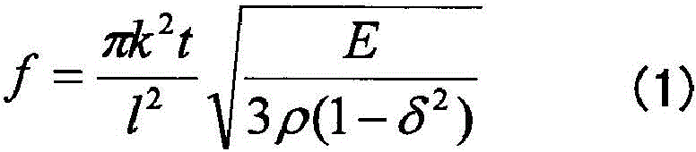
When the young's modulus E, the density ρ, the poisson's ratio δ, the long-side dimension l, the thickness t, and the number of cycles k of the standing wave existing in the long-side direction of the top panel 120 are used, the natural vibration number (resonance frequency) f of the top panel 120 is expressed by the following expressions (1) and (2). Since the standing waves have the same waveform in units of 1/2 cycles, the cycle number k is 0.5, 1, 1.5, and 2 ….
[ number 1]
[ number 2]
f=ak2(2)
The coefficient α of the formula (2) is k in the formula (1)2And other coefficients are collectively expressed.
As an example, the standing waves shown in fig. 4(a) and (B) are waveforms when the cycle number k is 10. For example, when Gorilla (registered trademark) glass having a length L of the long side of 140mm, a length of the short side of 80mm, and a thickness t of 0.7mm is used as the top panel 120, the natural frequency f becomes 33.5kHz when the cycle number k is 10. In this case, the 1 st drive signal and the 2 nd drive signal having a frequency of 33.5kHz may be used.
The top panel 120 is a flat plate-like member, but when the vibration elements 140A and 140B (see fig. 2 and 3) are driven to generate natural vibration in the ultrasonic frequency band, the natural vibration is bent as shown in fig. 4(a) and (B), and standing waves are generated on the surface 120A.
Here, as an example, a description will be given of a configuration in which a portion where the vibration element 140A is attached to the top panel 120 and a portion where the vibration element 140B is attached to the top panel 120 are portions that are antinodes of natural vibration generated in the top panel 120 and vibrate in the same phase.
Thus, the number of cycles k is an integer. When the number of cycles k is a small number (a number including an integer part and a decimal part), the part where the vibration element 140A is attached to the top panel 120 and the part where the vibration element 140B is attached to the top panel 120 may be the antinodes of the natural vibration that vibrates in the reverse phase, and therefore the vibration element 140A and the vibration element 140B may be driven in the reverse phase.
Next, the natural vibration of the ultrasonic frequency band generated in the top panel 120 of the electronic device 100 will be described with reference to fig. 5.
Fig. 5 is a diagram illustrating a state in which a kinetic friction force applied to a fingertip that performs an operation input is changed by natural vibration of an ultrasonic frequency band generated in the top panel 120 of the electronic apparatus 100. In fig. 5 (a) and (B), the user performs an operation input of moving a finger along an arrow from the back side to the front side of the top panel 120 while touching the top panel 120 with a fingertip.
Here, for easy understanding, a case will be described in which the dynamic friction force is changed by switching on/off of the vibration. The vibration is turned on/off by turning on/off the vibration elements 140A and 140B (see fig. 2 and 3).
In fig. 5 (a) and (B), in the depth direction of the top panel 120, the range touched by the finger during the period in which the vibration is off is represented by gray, and the range touched by the finger during the period in which the vibration is on is represented by white.
As shown in fig. 4, natural vibration in the ultrasonic frequency band occurs in the entire top panel 120, and fig. 5 (a) and (B) show operation patterns in which the vibration is switched on and off while the user's finger is moving from the back side to the near side of the top panel 120.
Therefore, in fig. 5 (a) and (B), in the depth direction of the top panel 120, the range touched by the finger during the period in which the vibration is off is represented by gray, and the range touched by the finger during the period in which the vibration is on is represented by white.
In the operation mode shown in fig. 5 (a), the vibration is off when the user's finger is located on the back side of the top panel 120, and the vibration is on while the finger is moving to the near side.
On the other hand, in the operation mode shown in fig. 5 (B), the vibration is on when the user's finger is located on the back side of the top panel 120, and the vibration is off while moving the finger to the near side.
Here, when natural vibration in the ultrasonic frequency band is generated in the top panel 120, an air layer due to the squeezing effect exists between the surface 120A of the top panel 120 and the finger, and the dynamic friction coefficient when the surface 120A of the top panel 120 is drawn with the finger decreases.
Therefore, in fig. 5 (a), the kinetic friction force applied to the fingertip is increased in the range indicated by gray on the back side of the top panel 120, and the kinetic friction force applied to the fingertip is decreased in the range indicated by white on the front side of the top panel 120.
Therefore, when the user performs an operation input to the top panel 120 as shown in fig. 5 (a), the user perceives a decrease in the kinetic friction force applied to the fingertip when the vibration is turned on, and perceives the fingertip to be easily slid. At this time, the user feels that there is a recess on the surface 120A of the top panel 120 when the kinetic friction force is reduced by making the surface 120A of the top panel 120 smoother.
On the other hand, in fig. 5 (B), the kinetic friction force applied to the fingertips is small in the range indicated by white on the back side of the top panel 120, and the kinetic friction force applied to the fingertips is large in the range indicated by gray on the near side of the top panel 120.
Therefore, as shown in fig. 5 (B), when the user performs an operation input to the top panel 120 turns the vibration to off, the user perceives that the kinetic friction force applied to the fingertip is increased, and perceives that the fingertip is less likely to slide or scrape. Further, the fingertips are less likely to slip, and thus, when the kinetic friction force is increased, the surface 120A of the top panel 120 is perceived to have a convex portion.
As can be seen from the above, in the case of fig. 5 (a) and (B), the user can feel the unevenness with the fingertips. The contents of human perception of unevenness are described in, for example, "ため color-based printing と" tactile "of tactile デザイン" (11 th th letter of the rules システムインテグレーション th letter (SI2010, fairland) ____ -177, 2010-12). Further, it is described in "Fishbone Tactile illumination" (Japanese society of バーチャルリアリティ, 10 th Reunion corpus (9.2005)).
Note that, although the change in the kinetic friction force when switching on/off the vibration is described here, this is the same as the case where the amplitudes (intensities) of the vibration elements 140A and 140B are changed.
Next, the configuration of the electronic device 100 according to the embodiment will be described with reference to fig. 6.
Fig. 6 is a diagram showing the configuration of the electronic apparatus 100 of the embodiment.
The electronic apparatus 100 includes vibration elements 140A and 140B, amplifiers 141A and 141B, a touch panel 150, a driver IC (Integrated Circuit) 151, a display panel 160, a driver IC161, capacitors 180A and 180B, a detection Circuit 190, a control section 200, a sine wave generator 310, and an amplitude modulator 320.
The control unit 200 includes an application processor 220, a communication processor 230, a drive control unit 240, a pressing operation determination unit 250, and a memory 260. The control unit 200 is realized by an IC chip, for example.
The capacitors 180A and 180B, the detection circuit 190, the drive control unit 240, the pressing operation determination unit 250, the sine wave generator 310, and the amplitude modulator 320 constitute the control device 300. Note that, although the embodiment in which the application processor 220, the communication processor 230, the drive control unit 240, the pressing operation determination unit 250, and the memory 260 are realized by 1 control unit 200 is described here, the drive control unit 240 may be provided as another IC chip or processor outside the control unit 200. In this case, data necessary for driving control of the driving control unit 240 among data stored in the memory 260 may be stored in a memory different from the memory 260 and may be provided in the control device 300.
In fig. 6, the case 110, the top panel 120, the double-sided tape 130, and the substrate 170 are omitted (see fig. 2). Here, the amplifiers 141A and 141B, the driver IC151, the driver IC161, the capacitors 180A and 180B, the detection circuit 190, the drive control unit 240, the pressing operation determination unit 250, the memory 260, the sine wave generator 310, and the amplitude modulator 320 will be described.
The amplifier 141A is connected to the control device 300, is connected to the vibration element 140A through the capacitor 180A, and amplifies the 1 st drive signal output from the control device 300 to drive the vibration element 140A. The amplifier 141B is connected to the control device 300, is connected to the vibration element 140B through the capacitor 180B, and amplifies the 2 nd drive signal output from the control device 300 to drive the vibration element 140B.
The driver IC151 is connected to the touch panel 150, detects position data indicating a position at which an operation input to the touch panel 150 has occurred, and outputs the position data to the control section 200. As a result, the position data is input to the application processor 220 and the drive control unit 240. In addition, input of the position data to the drive control section 240 is equivalent to input of the position data to the control device 300.
The driver IC161 is connected to the display panel 160, inputs drawing data output from the control device 300 to the display panel 160, and displays an image based on the drawing data on the display panel 160. In this way, a GUI operation unit, an image, and the like based on the drawing data are displayed on the display panel 160.
The capacitor 180A is inserted in series between the amplifier 141A and the vibration element 140A, and the capacitor 180B is inserted in series between the amplifier 141B and the vibration element 140B. The capacitors 180A and 180B are used for detecting a pressing operation performed on the top panel 120. The capacitors 180A and 180B are examples of the 1 st capacitor and the 2 nd capacitor, respectively.
The pressing operation is an operation of pressing the surface 120A of the top panel 120 without moving the fingertip in a state where the user brings the fingertip into contact with the surface 120A of the top panel 120. Such a pressing operation is used, for example, as an action for determining the input content. For example, when a predetermined GUI button is displayed on the display panel 160, if a pressing operation is performed in the display region of the GUI button, the pressing operation determination unit 250 determines that the pressing operation is performed, and the application processor 220 executes a function assigned to the GUI button.
The detection circuit 190 is provided between the capacitors 180A and 180B and the pressing operation determination unit 250, detects a voltage between both ends of each of the capacitors 180A and 180B, amplifies the voltage value, and outputs the amplified voltage value to the pressing operation determination unit 250. The detection circuit 190 will be described in detail later.
The application processor 220 is installed with an OS (Operating System) of the electronic device 100, and performs processing for executing various applications of the electronic device 100. When the pressing operation determination unit 250 determines that the pressing operation has been performed, the application processor 220 executes a function assigned to the GUI button that has been pressed.
The communication processor 230 executes processing required when the electronic device 100 performs communication such as 3g (generation), 4g (generation), lte (long Term evolution), WiFi, and the like.
When providing a tactile sensation using the squeezing effect, the drive control unit 240 outputs the 1 st amplitude data and the 2 nd amplitude data to the amplitude modulator 320 when the 2 predetermined conditions match. The drive control unit 240 is an example of the 1 st drive control unit and the 2 nd drive control unit.
The 1 st amplitude data and the 2 nd amplitude data are data indicating amplitude values for adjusting the intensities of the 1 st drive signal and the 2 nd drive signal used for driving the vibrating elements 140A and 140B when providing the tactile sensation using the squeezing effect. For example, the 1 st amplitude data and the 2 nd amplitude data are digital data indicating amplitude values for adjusting the intensities of the 1 st driving signal and the 2 nd driving signal at a frequency of 350 Hz. Here, a mode in which the 1 st amplitude data and the 2 nd amplitude data are equal will be described.
The amplitude value is set according to the degree of temporal change of the position data. Here, as the degree of temporal change of the position data, the speed at which the user's fingertip moves along the surface 120A of the top panel 120 is used. The drive control unit 240 calculates the movement speed of the user's fingertip based on the degree of temporal change of the position data input from the driver IC 151.
Further, the control device 300 according to the embodiment vibrates the top panel 120 so as to change the kinetic frictional force applied to the fingertip when the user's fingertip moves along the surface 120A of the top panel 120. Since the kinetic friction force is generated when the fingertip moves, drive control unit 240 vibrates vibration elements 140A and 140B when the movement speed is equal to or higher than a predetermined threshold speed. The movement speed is equal to or higher than a predetermined threshold speed, which is the 1 st predetermined condition.
Therefore, the amplitude values indicated by the 1 st amplitude data and the 2 nd amplitude data output from the drive control unit 240 are set to predetermined amplitude values indicating the sense of touch when the moving speed is equal to or higher than a predetermined threshold speed.
In addition, when the position of the fingertip performing the operation input is within a predetermined region where the vibration for providing the tactile sensation using the squeezing effect is generated, the control device 300 of the embodiment outputs the 1 st amplitude data and the 2 nd amplitude data for providing the tactile sensation to the amplitude modulator 320. The 2 nd predetermined condition is that the position of the fingertip making the operation input is located in a predetermined region where vibration should be generated.
Whether or not the position of the fingertip making the operation input is located inside the predetermined region where the vibration should be generated is determined based on whether or not the position of the fingertip making the operation input is located inside the predetermined region where the vibration should be generated.
Here, the position on the display panel 160, such as the GUI operation portion displayed on the display panel 160, the area where the image is displayed, or the area indicating the entire page, is determined based on the area data indicating the area. In all applications, area data exists for all GUI operation sections displayed on the display panel 160, for an area where an image is displayed, or for an area representing the entire page.
Therefore, the 2 nd predetermined condition is related to the type of application activated by the electronic apparatus 100 when it is determined whether or not the position of the fingertip making the operation input is within the predetermined region where the vibration for providing tactile sensation is generated. Since the display of the display panel 160 is different according to the kind of application.
In addition, the type of the operation input for moving the fingertip touching the surface 120A of the top panel 120 differs depending on the type of the application. As a type of operation input for moving a fingertip touching the front surface 120A of the top panel 120, there is a so-called flick operation, for example, when operating a GUI operation section. The flick operation is an operation of moving a fingertip by a relatively short distance along the surface 120A of the top panel 120 so as to be flicked (flicked).
In addition, when the page is rolled up, for example, a sliding operation is performed. The slide operation is an operation of moving the fingertip in a sweeping manner for a relatively long distance along the surface 120A of the top panel 120. The slide operation is performed when, for example, a photograph is rolled up, in addition to the case of rolling up a page. When the slider (see the slider 102B in fig. 1) based on the GUI operation portion is slid, a drag operation for dragging the slider is performed.
Here, as with a tap operation, a slide operation, and a drag operation, which are exemplified, the operation input of moving the fingertip that touches the surface 120A of the top panel 120 is used in a different manner depending on the type of display by the application. Therefore, when determining whether or not the position of the fingertip making the operation input is within a predetermined region where vibration should be generated, the type of application activated by the electronic apparatus 100 is related.
The drive control unit 240 determines, using the area data, whether or not the position indicated by the position data input from the driver IC151 is within a predetermined area in which vibration for providing tactile sensation should be generated.
Data stored in the memory 260, which is obtained by associating data indicating the type of application, area data indicating a GUI operation unit or the like that performs operation input, and pattern data indicating a vibration pattern, is stored in the memory 260.
When the drive control unit 240 provides the tactile sensation using the squeezing effect, the 2 nd predetermined conditions required to output the 1 st amplitude data and the 2 nd amplitude data to the amplitude modulator 320 are that the movement speed of the fingertip is equal to or higher than a predetermined threshold speed and that the coordinates indicating the position of the operation input are located inside a predetermined region in which the vibration should occur.
When a tactile sensation using the pinch effect is provided, if the moving speed of the fingertip is equal to or higher than a predetermined threshold speed and the operation-input coordinates are located inside a predetermined region in which vibration should occur, the drive control unit 240 reads the 1 st amplitude data and the 2 nd amplitude data indicating the amplitude value for providing the tactile sensation from the memory 260 and outputs the amplitude data to the amplitude modulator 320.
Further, when the user's fingertip touches the surface 120A of the top panel 120 and stops, the control device 300 vibrates the top panel 120 to detect the pressing operation. When the user stops his or her fingertip, the moving speed is lower than a predetermined threshold speed. When the moving speed is lower than the predetermined threshold speed, the amplitude values indicated by the 1 st amplitude data and the 2 nd amplitude data output from the drive control unit 240 are set to predetermined amplitude values for detecting the pressing operation.
The predetermined amplitude value for detecting the pressing operation is different from the amplitude value for providing tactile sensation and smaller than the amplitude value for providing tactile sensation. When switching from a predetermined amplitude value for detecting a pressing operation to an amplitude value for providing tactile sensation, the tactile sensation having a concave portion can be provided, and when the tactile sensation is reversed, the tactile sensation having a convex portion can be provided.
When the user's fingertip does not touch the top panel 120, that is, when no operation input is made, the amplitude values indicated by the 1 st amplitude data and the 2 nd amplitude data are set to zero, and the vibration elements 140A and 140B are not driven.
The pressing operation determination unit 250 is connected to the detection circuit 190, and determines whether or not a pressing operation has been performed based on a change in voltage between both ends of each of the capacitors 180A and 180B detected by the detection circuit 190. The pressing operation determination unit 250 is an example of the 1 st pressing determination unit and the 2 nd pressing determination unit.
When it is determined that the pressing operation is performed, the pressing operation determination unit 250 outputs a signal (pressing event) indicating that the pressing operation is performed to the application processor 220. As a result, the application processor 220 executes a function assigned to a predetermined GUI operation portion displayed at the position where the pressing operation is performed.
Here, the pressing operation is detected in a state where the vibration elements 140A and 140B are driven by the 1 st drive signal and the 2 nd drive signal.
The predetermined GUI operation unit is, for example, a GUI operation unit that receives a pressing operation as a GUI operation unit that represents an image of a button. The area in which the predetermined GUI operation portion is displayed is an area in which the GUI operation portion that accepts the pressing operation is displayed as the GUI operation portion that represents the image of the button. The press event is utilized when the application processor 220 executes various applications of the electronic device 100.
The memory 260 stores data in which data indicating the type of application, area data indicating a GUI operation unit or the like that performs operation input, and pattern data indicating a vibration pattern are associated with each other.
The memory 260 stores data and programs necessary for the application processor 220 to execute an application, data and programs necessary for the communication processor 230 to perform communication processing, and the like.
The sine wave generator 310 generates sine waves necessary for generating the 1 st and 2 nd driving signals for vibrating the top panel 120 by the natural vibration number. For example, when the top panel 120 is vibrated at the natural frequency f of 33.5kHz, the frequency of a sine wave is 33.5 kHz. The sine wave generator 310 inputs a sine wave signal of an ultrasonic frequency band to the amplitude modulator 320.
The sine wave signal generated by the sine wave generator 310 is an ac reference signal that is a source of the 1 st drive signal and the 2 nd drive signal generated by the natural vibration of the ultrasonic frequency band, and has a constant frequency and a constant phase. The sine wave generator 310 inputs a sine wave signal of an ultrasonic frequency band to the amplitude modulator 320.
In addition, although a mode using the sine wave generator 310 that generates a sine wave signal is described here, the sine wave signal may not be used. For example, a waveform signal that dulls a waveform of rising and falling of a clock may be used. Therefore, a signal generator that generates an alternating signal of an ultrasonic frequency band may be used instead of the sine wave generator 310.
The amplitude modulator 320 generates the 1 st driving signal and the 2 nd driving signal by modulating the amplitude of the sine wave signal input from the sine wave generator 310 using the 1 st amplitude data and the 2 nd amplitude data input from the driving control unit 240, respectively. The amplitude modulator 320 modulates only the amplitude of the sine wave signal of the ultrasonic frequency band input from the sine wave generator 310, and generates the 1 st drive signal and the 2 nd drive signal without modulating the frequency and the phase.
Therefore, the 1 st drive signal and the 2 nd drive signal output from the amplitude modulator 320 are ultrasonic-band sine wave signals in which only the amplitude of the ultrasonic-band sine wave signal input from the sine wave generator 310 is modulated.
Next, data stored in the memory 260 will be described with reference to fig. 7. Fig. 7 is a diagram showing data stored in the memory 260.
The data shown in fig. 7 is data in which data indicating the type of application, area data indicating coordinate values for displaying an area such as a GUI operation unit for performing operation input, and mode data indicating a vibration mode are associated with each other.
The vibration mode is a vibration mode used to vibrate the vibration element 140 when a user touches a fingertip to the top panel 120, and is used to generate the 1 st drive signal and the 2 nd drive signal. The vibration pattern is pattern data in which amplitude data used for generating the 1 st drive signal and the 2 nd drive signal are arranged in time series. For example, the amplitude data is arranged at 10kHz in the time axis direction. The amplitude data is used as the 1 st amplitude data and the 2 nd amplitude data. Therefore, the 1 st amplitude data and the 2 nd amplitude data are equal to each other.
Fig. 7 shows an application id (identification) as data indicating the type of application. Further, the area data are expressions f1 to f5 showing coordinate values of an area such as a GUI operation unit for performing operation input. Further, pattern data representing vibration patterns are shown as P1 to P5.
The vibration patterns represented by the pattern data P1 to P4 are vibration patterns used to reduce the coefficient of dynamic friction applied by the fingertip to the surface 120A depicting the top panel 120 by the squeezing effect and to change the intensity of the vibration to provide a tactile sensation when the position of the operation input is moved. The pattern data P1 to P4 are associated with expressions f1 to f4, respectively, which indicate coordinate values of a region where a GUI operation unit or the like is displayed.
The vibration pattern indicated by the pattern data P5 is a vibration pattern used to vibrate the vibration element 140 at a predetermined constant amplitude value for detecting a pressing operation when the position of the operation input is not moved and is stopped. The expression f5 associated with the pattern data P1 represents the entire display area of the display panel 160. That is, regardless of the position of the operation input in the display region of the display panel 160, when the position of the operation input is stopped, the vibration element 140 vibrates at a predetermined constant amplitude value for detecting the pressing operation.
In addition, the applications represented by the application ID included in the data stored in the memory 260 include all applications available by the smartphone terminal or the tablet computer, and also include an editing mode of e-mail.
Fig. 8 is a diagram illustrating a portion related to determination of a pressing operation among the electronic apparatus 100. Fig. 8 shows the top panel 120, the vibration element 140A, the capacitor 180A, the detection circuit 190, and the driver 330 in the electronic apparatus 100.
The driver 330 represents the amplifiers 141A and 141B, the drive controller 240, the pressing operation determining unit 250, the memory 260, the sine wave generator 310, and the amplitude modulator 320 shown in fig. 6 as 1 processing unit.
The detection circuit 190 has a differential amplifier 191 and a low-pass filter 192. In fig. 8, the differential amplifier 191 and the low-pass filter 192 connected to the capacitor 180A are shown among the components of the detection circuit 190, but the detection circuit 190 actually further includes a differential amplifier and a low-pass filter connected to the capacitor 180B.
The capacitor 180A and the capacitor 180B have the same configuration, and the differential amplifier and the low-pass filter connected to the capacitor 180B have the same configuration as the differential amplifier 191 and the low-pass filter 192. Therefore, the differential amplifier 191 and the low-pass filter 192 connected to the capacitor 180A will be described here.
The differential amplifier 191 of the detection circuit 190 that detects the voltage between the two ends of the capacitor 180A is an example of the 1 st voltage detection unit, and the differential amplifier of the detection circuit 190 that detects the voltage between the two ends of the capacitor 180B is an example of the 2 nd voltage detection unit.
A non-inverting input terminal (+) and an inverting input terminal (-) of the differential amplifier 191 are connected to both ends of the capacitor 180A, respectively. In fig. 8, the input impedance R of the differential amplifier 191 as viewed from the capacitor 180A is shown between the non-inverting input terminal (+) and the inverting input terminal (-) of the differential amplifier 191. The output terminal of the differential amplifier 191 is connected to the input terminal of the low-pass filter 192. The differential amplifier 191 amplifies the voltage between both ends of the capacitor 180A and outputs the amplified voltage to the low-pass filter 192.
The input terminal of the low-pass filter 192 is connected to the output terminal of the differential amplifier 191, and the output terminal is connected to the pressing operation determination unit 250 shown in fig. 6. The low-pass filter 192 passes the voltage signal input from the differential amplifier 191 through a bandwidth equal to or less than a predetermined cutoff frequency, and outputs the voltage signal to the pressing operation determination unit 250. The cutoff frequency may be set to a frequency at which components in the ultrasonic frequency band can be removed, based on the output of the differential amplifier 191.
The low-pass filter 192 can be implemented by an rc circuit including a resistor r and a capacitor c, or a circuit that performs a/d (analog to digital) conversion on an input signal and then removes components above a cutoff frequency by numerical calculation.
Fig. 9 is a diagram for explaining the principle of detecting a pressing operation. In fig. 9, a closed circuit including a vibration element 140A and a capacitor 180A is shown.
The vibration element 140A includes a piezoelectric body 140A1 and electrodes 140AA and 140 AB. Capacitor 180A has electrodes 180AA and 180 AB. Electrode 140AA is connected to electrode 180AB, and electrode 140AB and electrode 180AA are grounded.
When the surface 120A of the top panel 120 (see fig. 8) is pressed, the vibration element 140A attached to the surface opposite to the surface 120A of the top panel 120 is pressed and deformed.
Polarization occurs when the piezoelectric body 140a1 deforms, and surface charges + Q and-Q appear on both sides of the piezoelectric body 140a 1. Here, the surface of the piezoelectric body 140a1 and the electrodes 140AA and 140AB formed on the surface of the piezoelectric body 140a1 are considered separately.
In order to cancel out surface charges + Q and + Q due to polarization by flowing a current through the closed circuit, charges-Q and + Q opposite to the surface charge of the piezoelectric body 140a1 are accumulated in the electrodes 140AA and 140AB, respectively.
However, when the vibration element 140A is viewed from the outside, the surface charges + Q and-Q of the piezoelectric body 140A1 and the charges-Q and + Q of the electrodes 140AA and 140AB are cancelled out, and no voltage is generated between the piezoelectric body 140A1 and the electrodes 140AA and 140AB, so that the deformation of the vibration element 140A cannot be detected.
Therefore, as shown in fig. 8, if capacitor 180A is connected in series between vibration element 140A and drive unit 330, and the 1 st drive signal is applied to vibration element 140A from drive unit 330 via capacitor 180A, when vibration element 140A is deformed, the state of charge as shown in fig. 9 can be detected by differential amplifier 191.
When the surface charge of the piezoelectric body 140A1 caused by the deformation of the vibration element 140A is defined as + Q and-Q and the charge accumulated in the electrode 140AA of the piezoelectric body 140A1 is defined as-Qa, the electrode 140AA is connected to the electrode 180AB of the capacitor 180A, and therefore the charge of the electrode 180AB becomes + Qa. In this way, the opposite charge-Qa is accumulated in the electrode 180AA of the capacitor 180A. In the electrode 140AB of the piezoelectric body 140a1, charge + Qa opposite to the electrode 140AA is accumulated.
If the voltage between both ends of vibration element 140A is set to V0 and the voltage between both ends of capacitor 180A is set to V1, the closed circuit including vibration element 140A and capacitor 180A is grounded, and therefore equation (3) is established.
V0+V1=0 (3)
Note that if the capacitance of the capacitor 180A is C1, the following expression (4) holds for the capacitor 180A.
Qa=C1×V1 (4)
The relation of Q ═ C × V holds true for the vibration element 140A, including not only the electric charges of the electrodes 140AA and 140AB but also the surface charges + Q and-Q of the piezoelectric body 140A1 caused by deformation. Therefore, if the capacitance of vibration element 140A is C0, equation (5) holds.
-Q+Qa=C0×V0 (5)
When equations (4) and (5) are substituted into equation (3), the following applies.
(-Q+Qa)/C0+Qa/C1=0
If the strain is further increased, equation (6) is obtained as follows.
Qa(1/C0+ 1/C1)=Q/C0
Qa(C1+C0)/(C0×C1)=Q/C0
Qa=Q×C1/(C0+C1) (6)
When formula (6) is rewritten using formula (4), formula (7) is obtained.
V1=Q/(C0+C1) (7)
As can be seen from equation (7), the voltage V1 between the two ends of the capacitor 180A is generated in proportion to the absolute values of the surface charges + Q and-Q generated in the piezoelectric body 140A1 by the deformation. In addition, the voltage V0 between the two ends of the vibration element 140 is generated with a sign opposite to the voltage V1.
As described above, by insulating vibration element 140A and driving unit 330 from each other with capacitor 180A in a direct current manner, a voltage signal due to deformation of vibration element 140 can be detected by capacitor 180A or vibration element 140A.
The 1 st drive signal (high-frequency voltage signal) output from the drive unit 330 is divided into the vibration element 140A and the capacitor 180A in the configuration of fig. 8. In general, the impedance of the capacitor C is 1/ω C (ω is an angular frequency), and therefore if the vibration element 140A is also a capacitor similarly, the ratio of the voltages of the vibration element 140A and the capacitor 180A becomes 1/C0:1/C1 — C1: C0.
Therefore, the high-frequency voltage signal of driver 330 is mainly applied to vibration element 140A, and in order to efficiently vibrate top panel 120, it is preferable to make capacitance C1 of capacitor 180A larger than capacitance C0 of vibration element 140A.
However, according to equation (7), the larger the capacitance C1, the smaller the voltage generated by the deformation of the vibration element 140A, and therefore the value of the capacitance C1 needs to be determined so as to maintain balance. For example, if the capacitance C1 is about 10 times the capacitance C0, the top panel 120 can sufficiently detect the voltage generated by the deformation of the vibration element 140A while paying attention to the efficiency of vibration.
In the circuit system including the vibration element 140A, the capacitor 180A, the detection circuit 190, and the driver 330 as shown in fig. 8, the time for which the voltage is held in the capacitor 180A may be determined by the values of the input impedance (input resistance) R and the capacitance C1+ C0 of the detection circuit 190, and the time constant may be R × (C1+ C0). Since the operation (pressing operation) of pressing the top panel 120 is performed for about 1 second, the input impedance R may be designed so as to be equal to or longer than a time required for the pressing operation with respect to the time constant. For example, if the capacitance C1+ C0 is 1 μ F, the time constant is about 10 seconds if the input impedance R is set to 10M Ω, and the design is suitable for detecting the pressing operation.
Fig. 10 is a graph showing a temporal change in voltage between both ends of the capacitor 180A. The horizontal axis represents time t (seconds), and the vertical axis represents voltage (unitless) between both ends. Fig. 11 is a diagram showing the output of the low-pass filter 192. The horizontal axis represents time t (seconds), and the vertical axis represents the signal level (unitless) of the pressing signal. The signal level is a voltage value.
As shown in fig. 10, the voltage between the two ends of the capacitor 180A has a signal waveform in which a high-frequency voltage (the 1 st drive signal) and a voltage signal generated by pressing are superimposed. In fig. 10, the frequency of the high frequency is shown as a frequency much lower than the actual frequency for easy understanding of the signal waveform. In addition, a voltage signal generated by pressing is hereinafter referred to as a pressing signal.
When the high-frequency component is removed by the low-pass filter 192, a signal waveform shown in fig. 11 is obtained. The signal waveform shown in fig. 11 is a pressing signal indicating that the top panel 120 is pressed in the vicinity of 0.6 second on the horizontal axis. The push signal is a voltage signal having a frequency very low compared to a high-frequency voltage (the 1 st drive signal in the ultrasonic band) and a slow change in amplitude, and therefore is easily extracted by the low-pass filter 192.
In order to detect a pressing operation from such a pressing signal, a predetermined determination threshold Vth may be set, and it is determined that a pressing operation has been performed when the pressing signal is equal to or greater than the predetermined determination threshold Vth. The pressing operation determination unit 250 may perform such determination processing.
However, even if the user presses the top panel 120 with a constant force, the amount of deformation of the vibration element 140A varies depending on the position of the pressing, and the voltage value of the voltage between the two ends of the electrodes 180AA and 180AB of the capacitor 180A also varies. Since the vibration element 140A is a member that is elongated in a plan view along the X axis and is provided at the end portion on the Y axis negative direction side of the top panel 120, most of the top panel 120 is a region where the vibration element 140A is not provided, and the distance to the vibration element 140A is different.
In this way, when the voltage value of the voltage between the two ends of the capacitor 180A differs depending on the position where the pressing operation is performed, the determination threshold Vth may be made different depending on the position of the plane of the top panel 120 when the pressing operation is detected with high accuracy even when the pressing operation is performed with a weak force at a position (for example, the center portion in the Y axis direction of the top panel 120) away from the vibration element 140A.
Further, if a plurality of determination threshold values Vth having different levels are provided at each position of the top panel 120, it is very advantageous to enable a user to select input contents in accordance with the level of the pressing force.
Fig. 12 is a diagram showing a database of the judgment threshold Vth. In the database of the determination threshold Vth, the determination threshold Vth is assigned to a total of 40 points of 5 points at equal intervals in the X-axis direction and 8 points at equal intervals in the Y-axis direction in the XY coordinates of the touch panel 150. The position of 40 dots to which the determination threshold Vth of 40 dots is assigned is determined by XY coordinates.
Fig. 12 shows that the determination threshold Vth (X, Y) allocated to 40 dots is represented by Vth (1,1) to Vth (5, 8). The determination threshold Vth (X, Y) is set to a low value on the X-axis negative direction side and the X-axis positive direction side in the X-axis direction, to a high value in the X-axis center portion, to a high value on the Y-axis negative direction side and the Y-axis positive direction side in the Y-axis direction, and to a low value in the Y-axis center portion.
Since the X-axis negative direction side and the X-axis positive direction side are positions distant from the vibration elements 140A, 140B in the X-axis direction, the center portion is a position distant from the vibration elements 140A, 140B in the Y-axis direction.
The determination threshold Vth in the pressed position may be calculated by storing the database of the determination threshold Vth in the memory 260, reading the values of the plurality of determination thresholds Vth around the pressed position, and performing interpolation processing using the relationship between the pressed position and the positions allocated to the plurality of determination thresholds Vth. The pressing operation determination unit 250 may perform such processing.
Next, a process executed by the drive control unit 240 of the control device 300 of the electronic apparatus 100 according to the embodiment will be described with reference to fig. 13.
Fig. 13 is a flowchart showing a process executed by the drive control unit 240 of the control device 300 of the electronic apparatus 100 according to the embodiment.
The os (operating system) of the electronic apparatus 100 executes control for driving the electronic apparatus 100 every predetermined control cycle. Therefore, the control device 300 performs calculation at predetermined control cycles. In this regard, the same applies to the drive control unit 240, and the drive control unit 240 repeatedly executes the flow shown in fig. 13 at predetermined control intervals.
By turning on the power of the electronic apparatus 100, the drive control unit 240 starts processing.
The drive control unit 240 determines whether or not an operation input is made (step S1). The process of step S1 is a process of determining whether or not an operation input has been made by determining whether or not position data is output from the touch panel 150. When no operation input is made, when position data indicating an indefinite position is output from touch panel 150, whether or not an operation input has been made may be determined based on whether or not the position data indicates XY coordinates.
When determining that an operation input has been made (yes in S1), the drive control unit 240 acquires region data associated with the vibration pattern for the GUI operation unit that made the current operation input, based on the coordinates indicated by the current position data and the type of the current application (step S2).
The drive control unit 240 determines whether or not the moving speed is equal to or higher than a predetermined threshold speed (step S3). The moving speed may be calculated by vector operation. The threshold speed may be set to the lowest speed of the movement speed of the fingertip when the operation input is performed while moving the fingertip, such as a flick operation, a slide operation, or a drag operation. Such a minimum speed may be set according to the experimental result, or may be set according to the resolution of touch panel 150.
When it is determined in step S3 that the movement speed is equal to or higher than the predetermined threshold speed, the drive control unit 240 determines whether or not the position of the operation input indicated by the position data obtained in step S2 is within the region St indicated by the region data (step S4).
When it is determined that the position of the operation input is in the region St, the drive control unit 240 reads out amplitude data indicating an amplitude value corresponding to the moving speed obtained in step S3 from the pattern data (step S5).
The drive control unit 240 outputs the amplitude data (step S6). Thus, the amplitude modulator 320 generates a modulation signal by modulating the amplitude of the sine wave output from the sine wave generator 310, generates a drive signal based on the modulation signal, and drives the vibration element 140.
On the other hand, when determining that no operation input has been made in step S1 (no in S1) (no in S1), the drive control unit 240 sets the amplitude data to zero (step S8). Since no operation is performed, the amplitude is set to zero, and the vibration elements 140A, 140B are not driven.
When it is determined that the operation input is performed (yes in S1), when it is determined in step S3 that the moving speed is not equal to or higher than the predetermined threshold speed (no in S3), and when it is determined in step S4 that the position of the operation input is not located in the region St, the drive control unit 240 sets a predetermined constant amplitude value for detecting the pressing operation (step S7). This is for the purpose of conforming to the detection of the pressing operation.
As a result, the drive control unit 240 outputs amplitude data indicating a predetermined constant amplitude value for detecting the pressing operation, and the amplitude modulator 320 generates a modulation signal in which the amplitude of the sine wave output from the sine wave generator 310 is modulated. In this case, the vibration element 140 is driven at a predetermined constant amplitude value for detecting the pressing operation.
Next, the operation of the drive control unit 240 when an operation input is made in the operation mode in which the application of the computer is executed in the electronic device 100 according to the embodiment will be described with reference to fig. 14 and 15. Fig. 14 and 15 are diagrams illustrating an operation example of the electronic apparatus 100 according to the embodiment.
As shown in fig. 14, in the operation mode for executing the application of the computer, when the fingertip is moved leftward from a state where the fingertip of the user touches the '6' of the numeral, and the movement operation input for drawing in the order of '5' and '4' of the numeral is performed, the top panel 120 is vibrated as follows. Such a movement operation input is an operation input performed while a fingertip moves across a plurality of GUI operation sections in a state where the plurality of GUI operation sections are arranged and displayed.
The amplitude of the drive signal is set to zero before time t0 when the user touches the top panel 120 with a fingertip.
In a state at time t0 when the user's fingertip starts to touch the top panel 120, the drive control unit 240 drives the vibration elements 140A and 140B with a drive signal set to a constant amplitude a1 for detecting the pressing operation. The amplitude a1 is amplitude data. At this point in time, the user touches the top panel 120 in a stopped state without moving his or her fingertip. That is, the operation input (stop operation input) is performed in a state where the fingertip is stopped, and the movement operation input or the pressing operation is not performed.
Then, at time t1, the user starts moving the fingertip at position C21 (see fig. 14) on the '6' position of the touched digit. Then, when the fingertip is slightly moved from the position C21, the vibration H1 with a large amplitude a2 is generated in a short time at a time t2 when the position of the fingertip moves outside from the region of the digit '6' and enters the digit '5'. The vibration H1 has a vibration mode in which vibrations having an amplitude a1 are added in a short time.
The vibration H1 is generated by moving the position of the fingertip outside from the region of the digit ' 6 ', and provides the user with a sense of touch of the fingertip on the protrusion by instantaneously changing the user's fingertip from a low-friction state in a short time to a high-friction state in a degree that is imperceptible.
In addition, if the fingertip is further moved in the left direction inside the '5' of the number, small vibration H2 based on the amplitude A3 is generated at constant time intervals in a short time from the time t 3. The vibration H1 has a vibration pattern in which vibrations having an amplitude a1 are added to vibrations having a small amplitude generated at constant intervals in a short time.
This is because the '5' of the number is located at the center of the numeric key, so that the user can perceive the vibration generated by touching the '5' of the number only by the feeling of the fingertip without visually observing the top panel 120. For example, the amplitude A3 is about 2 times the amplitude a 1.
Then, at time t4, if the fingertip moves out of the region of the digit '5' and enters the region of the digit '4', vibration H3 of large amplitude a2 is generated in a short time. Since the vibration H3 is the same vibration as the vibration H1, the user is given a tactile sensation of touching the protrusion with the fingertip by instantaneously changing the fingertip of the user from a low friction state to a high friction state in a short time of a left and right side where the user is not aware, and the user is thereby perceived that the fingertip enters the region of the digit '4' from the region of the digit '5'.
Thus, the user can perceive that '6', '5', and '4' of the numbers are drawn in order.
At time t5, if the user stops his or her fingertip, drive control unit 240 drives vibration elements 140A and 140B with a drive signal set to a constant amplitude a1 for detecting a pressing operation.
Then, at time t6, the user starts the pressing operation, and at time t7, the pressing operation is detected by the pressing operation determination unit 250, and the pressing operation is ended. In this state, since the user's fingertip does not move along top panel 120, drive control unit 240 drives vibration elements 140A and 140B while maintaining the amplitude value at a 1.
After time t7 has elapsed, since the fingertip of the user touches the top panel 120 and the operation input is performed, but the operation is stopped, the drive controller 240 drives the vibration elements 140A and 140B with the drive signal set to the amplitude a1 in order to detect the pressing operation state at the upper level.
Fig. 16 is a flowchart showing a process of determining a pressing operation by the pressing operation determination unit 250.
The pressing operation determination unit 250 starts (starts) processing when the power of the electronic apparatus 100 is turned on.
The pressing operation determination unit 250 reads the voltage value input from the 2 low-pass filters 192 connected to the capacitors 180A and 180B and the position data input from the touch panel 150 (step S11).
The pressing operation determination unit 250 reads out the plurality of determination threshold values Vth present around the coordinates indicated by the position data read out in step S11 from the database of determination threshold values Vth stored in the memory 260, and performs interpolation processing to calculate the determination threshold value Vth in the coordinates indicated by the position data (step S12).
The pressing operation determination unit 250 determines whether or not at least 1 of the 2 voltage values read in step S11 is equal to or greater than the determination threshold Vth obtained in step S12 (step S13).
When at least 1 of the read 2 voltage values is equal to or greater than the determination threshold Vth (yes at S13), the pressing operation determination unit 250 determines that the pressing operation has been performed (step S14).
On the other hand, when both of the read 2 voltage values are not equal to or greater than the determination threshold Vth (no in S13), the pressing operation determination unit 250 determines that the pressing operation is not performed (step S15).
When the processing in step S14 or S15 is finished, the pressing operation determination unit 250 ends the series of processing (end). The pressing operation determination unit 250 repeatedly executes the processing from the start to the end for each predetermined system cycle while the electronic apparatus 100 is powered on.
As described above, control device 300 monitors the voltage between both ends of capacitors 180A and 180B inserted in series between amplifiers 141A and 141B and vibration elements 140A and 140B.
The voltage V1 between the both ends of the capacitors 180A and 180B can be obtained by calculating according to the above-described equations (3) to (7) using the capacitors 180A and 180B and taking into account the surface charges of the piezoelectric body 140A1 (see fig. 9) as + Q and-Q.
Further, the voltage V1 between the two ends is amplified by the differential amplifier 191, and then the high frequency components (the 1 st drive signal and the 2 nd drive signal) are removed by the low-pass filter 192, whereby the pressing signal of the user is obtained as shown in fig. 11.
The pressing operation determination unit 250 calculates a determination threshold Vth at a position where the pressing operation is performed, and determines whether or not the voltage generated by the pressing operation is equal to or greater than the determined determination threshold Vth, thereby determining whether or not the pressing operation is performed.
While no operation input is being made, the drive control unit 240 drives the vibration elements 140A and 140B using the 1 st drive signal and the 2 nd drive signal of the constant amplitude a1 for detecting the pressing operation. Therefore, when the user touches the top panel 120 without touching the top panel 120 with a fingertip and performs a pressing operation without moving the fingertip, the 1 st drive signal and the 2 nd drive signal are removed by the low-pass filter 192, and a pressing signal in the case where the user performs the pressing operation without moving the fingertip can be obtained. Further, the pressing can be detected by comparing the voltage signal with the determination threshold.
In addition, when the movement speed is smaller than the threshold speed although the operation input is made and when the movement speed is not in the predetermined region St although the operation input is made and the movement speed is equal to or higher than the threshold speed, the drive control unit 240 drives the vibration elements 140A and 140B using the 1 St drive signal and the 2 nd drive signal of the constant amplitude a1 for detecting the pressing operation. Therefore, the pressing operation can be detected as well.
When the movement speed is equal to or higher than the threshold speed and in the predetermined region St by the operation input, the drive control unit 240 drives the vibrating elements 140A and 140B by using the 1 St drive signal and the 2 nd drive signal obtained by further adding the amplitude for tactile sensation to the constant amplitude a1 for detecting the pressing operation.
Therefore, by removing the 1 St drive signal and the 2 nd drive signal by the low-pass filter 192, a pressing signal in the case where the user performs a pressing operation while moving the fingertip in the predetermined region St can be obtained. By comparing the voltage signal with the determination threshold, it is possible to detect that the pressing has been performed. Since the change in the amplitude indicating the sense of touch included in the 1 st drive signal and the 2 nd drive signal is removed as the 1 st drive signal and the 2 nd drive signal by the low-pass filter 192, such a voltage signal as shown in fig. 11 can be obtained even when the pressing operation is performed while moving the fingertip.
In this way, the control device 300 can detect both the pressing operation performed by stopping the fingertip and the pressing operation performed by moving the fingertip.
Here, the constituent elements used for such pressing determination are the capacitors 180A and 180B, the detection circuit 190, and the pressing operation determination unit 250.
The differential amplifier 191 and the low-pass filter 192 of the detection circuit 190 may be disposed between the capacitors 180A and 180B and the control unit 200 as an electric circuit configuration, and may be spatially disposed in a small space such as a gap inside the electronic device 100.
In addition, the pressing operation determination section 250 is included inside the control section 200 implemented by an IC chip.
Therefore, the control device 300 including the capacitors 180A and 180B, the detection circuit 190, and the pressing operation determination unit 250 can be realized with a very simple configuration.
According to the above embodiments, the control device 300, the electronic apparatus 100, and the method for controlling the electronic apparatus 100 having a simple configuration can be provided.
In addition, the above description has been given of a mode in which the pressing operation is used as an operation for specifying the input content. However, in addition to this, a pressing operation may be used.
For example, the pressing signal may be used to control the amplitude data output from the ultrasonic vibration drive control unit 240. The effect of reducing the dynamic friction coefficient by the ultrasonic vibration tends to be reduced when the pressing force is large, and therefore, when the voltage level of the pressing signal is large, adjustment is performed so that the amplitude is increased.
In addition, when the coefficient of dynamic friction is substantially constant regardless of the pressing force, the force required to move the fingertip along the surface 120A while touching the top panel 120 is proportional to the product of the pressing force and the coefficient of dynamic friction, and therefore the force required to move the fingertip along the surface 120A when the pressing force is large.
When the pressing force is large, the dynamic friction coefficient is reduced, and adjustment is performed so that the amplitude data output from the drive control unit 240 becomes large when the voltage level of the pressing signal is large in order to facilitate movement of the fingertip along the surface 120A.
In order to perform these controls, the voltage level of the push signal, and the amplitude data and the reinforcing rate output by the drive control section 240 may be determined in advance and stored in the memory 260 as data.
In addition, the above description has been given of a mode in which the drive control unit 240 outputs the drive signal of the ultrasonic frequency band as the 1 st drive signal and the 2 nd drive signal to generate the natural vibration of the ultrasonic frequency band in the top panel 120. However, the vibration generated by the top panel 120 may not be a natural vibration of the ultrasonic frequency band, but may be a natural vibration of a frequency band (for example, audible range) lower than the ultrasonic frequency band. In this case, the sine wave generator 310 may output a sine wave in the audible range. Further, the vibration generated in the top panel 120 may not be a natural vibration.
In addition, although the embodiment in which 2 amplifiers 141A and 141B are connected to the vibration elements 140A and 140B has been described above, 2 amplifiers 141A and 141B may be replaced with 1 amplifier, and 1 amplifier may output the 1 st drive signal and the 2 nd drive signal.
In addition, the pressing operation determination unit 250 is provided inside the control unit 200 independently of the application processor 220, which has been described above. However, the pressing operation determination unit 250 may be included in the application processor 220. In this case, the pressing operation determination section 250 may be a function realized by the OS of the application processor 220.
In addition, although the description has been given above of the mode in which the amplitudes of the 1 St drive signal and the 2 nd drive signal are maintained at the constant amplitude a1 in the case other than the case where the user performs the operation input and the moving speed is equal to or higher than the threshold speed and the position of the operation input is in the predetermined region St, the amplitude a1 may be set to zero. This is equivalent to the case where the amplitude modulator 320 does not output a drive signal. The amplitude a1 is set to zero, which means that the 1 st amplitude data and the 2 nd amplitude data are set to zero.
Even in such a case, detection can be similarly performed when the user performs the operation input, the moving speed is equal to or higher than the threshold speed, and the pressing operation is performed when the position of the operation input is in the predetermined region St.
In addition, in the case other than the above, in a state where the vibration elements 140A and 140B are not driven, the voltage generated in the capacitors 180A and 180B by pressing the top panel 120 is amplified by the differential amplifier 191, and a pressing signal such as that shown in fig. 11 is obtained by the low-pass filter 192. Therefore, the pressing operation determination unit 250 can detect the pressing operation as in the case where the amplitude a1 is not zero.
In the push signal shown in fig. 11, a drift component whose level rises as a whole is superimposed at a lower frequency than the push signal. This can be observed in experiments in the actual roof panel 120, presumably due to the temperature rise caused by driving the vibration element 140A with the 1 st drive signal. The drift component is represented by a curve of time from 1 second to 1.2 seconds, which extends from the curve of time in the vicinity of 0 second to 0.2 second in fig. 11.
When there is a possibility that the accuracy of determination of the pressing operation is lowered due to such a drift component, the following detection circuit 190M1 may be used instead of the detection circuit 190 shown in fig. 8. Fig. 17 is a diagram showing a1 st modification of a portion related to determination of a pressing operation among the electronic apparatus 100. In fig. 17, a detection circuit 190M1 is provided instead of the detection circuit 190 shown in fig. 8.
The detection circuit 190M1 has a differential amplifier 191 and a band-pass filter 192M 1. That is, the detection circuit 190M1 has a configuration in which the low-pass filter 192 of the detection circuit 190 shown in fig. 8 is replaced with a band-pass filter 192M 1.
A band pass filter 192M1 may be provided on the output side of the differential amplifier 191 to remove the high frequency (1 st drive signal) component and the drift component. Similarly to the low-pass filter 192 (see fig. 8), the band-pass filter 192M1 may be any band-pass filter that has both the function of a low-pass filter that removes a component of a high frequency (1 st drive signal) and the function of a high-pass filter that passes a push signal and removes a drift component of a frequency lower than the push signal.
Fig. 18 is a diagram showing the pressing signal output from the band-pass filter 192M 1. The pressing signal shown in fig. 18 has a waveform from which a drift component is removed, compared with the pressing signal shown in fig. 11.
Although the embodiment in which the detection circuit 190 includes the low-pass filter 192 has been described above, the low-pass filter 192 may not be included when the pressing determination can be performed without using the low-pass filter 192.
Fig. 19 is a diagram showing a2 nd modification of a portion relating to determination of a pressing operation in the electronic apparatus 100. In fig. 19, a detection circuit 190M2 is provided instead of the detection circuit 190 shown in fig. 8. The detection circuit 190M2 includes the differential amplifier 191 and does not include the low-pass filter 192 (see fig. 8). In this case, the determination threshold may be 2.5 of the level on the ordinate in fig. 10, for example.
Fig. 20 is a diagram showing a3 rd modification of a portion related to determination of a pressing operation among the electronic apparatus 100. In fig. 20, a detection circuit 190M3 is provided in place of the detection circuit 190M2 shown in fig. 19.
The detection circuit 190M3 includes the differential amplifier 191M3 and does not include the low-pass filter 192 (see fig. 8) as in the detection circuit 190M 2. Differential amplifier 191M3 is connected not to capacitor 180A but to both ends of vibration element 140A, and detects voltage V0 between both ends of vibration element 140A.
Since the closed circuit including vibration element 140A and capacitor 180A is grounded, the following equation (3) described above is established, and thus V0 becomes — V1. Therefore, the detection circuit 190M3 can detect the pressing signal superimposed with the 1 st drive signal, similarly to the detection circuit 190M 2.
Next, a connection mode between driving unit 330, vibration elements 140A and 140B or vibration element 140A, and capacitors 180A and 180B or capacitor 180A will be described with reference to fig. 21 to 24. Fig. 21 to 24 are diagrams showing connection forms of portions related to determination of the pressing operation.
Fig. 21 shows a connection mode in which vibration elements 140A and 140B are provided on top panel 120, and vibration elements 140A and 140B are connected to drive unit 330 via capacitors 180A and 180B, respectively. Such a connection mode corresponds to the connection mode between vibration elements 140A and 140B, capacitors 180A and 180B, and driving unit 330 shown in fig. 6. In fig. 8, for convenience of explanation, only vibration element 140A and capacitor 180A are shown.
In the electronic apparatus 100 shown in fig. 6, the part where the vibration element 140A is attached to the top panel 120 and the part where the vibration element 140B is attached to the top panel 120 are parts of antinodes of natural vibration that vibrates in the reverse phase, and therefore the vibration element 140A and the vibration element 140B are driven in the reverse phase.
Therefore, as shown in fig. 21, vibration element 140A and vibration element 140B are connected in reverse polarity as follows. Here, the vibration element 140A has electrodes 140AA and 140AB, and the vibration element 140B has electrodes 140BA and 140 BB. Electrode 140AA and electrode 140BA are electrodes of the same polarity, and electrode 140AB and electrode 140BB are electrodes of the same polarity.
In this case, the electrode 140AA of the vibration element 140A is connected to the driver 330 via the capacitor 180A, and the electrode 140AB is connected to the driver 330 and the electrode 140BA of the vibration element 140B. Electrode 140BA of vibration element 140B is connected to drive unit 330 and electrode 140AB of vibration element 140A, and electrode 140BB is connected to drive unit 330 via capacitor 180B.
In the connection mode shown in fig. 21, the detection circuit 190 (see fig. 8), the detection circuit 190M1 (see fig. 17), the detection circuit 190M2 (see fig. 19), or the detection circuit 190M3 (see fig. 20) may be connected to both of the capacitors 180A and 180B or both of the vibration elements 140A and 140B to detect the voltage between both ends.
In the case where the vibration elements 140A and 140B are connected in reverse polarity as described above, if capacitors are provided between the driver 330 and the branching point a between the electrode 140AA of the vibration element 140A and the electrode 140BB of the vibration element 140B instead of the capacitors 180A and 180B shown in fig. 21, signals of reverse polarity cancel each other out, and it is necessary to pay attention to the positions where the capacitors are provided.
Fig. 22 shows a connection mode in which vibration elements 140A and 140B are provided on top panel 120, and vibration elements 140A and 140B are connected to drive unit 330 via capacitors 180A and 180B, respectively.
The connection mode shown in fig. 22 is a case where a portion where vibration element 140A is attached to top panel 120 and a portion where vibration element 140B is attached to top panel 120 are antinodes of natural vibration that vibrates in phase. In this case, the vibration element 140A and the vibration element 140B are connected in the same polarity and driven in phase.
In the connection mode shown in fig. 22, the detection circuit 190 (see fig. 8), the detection circuit 190M1 (see fig. 17), the detection circuit 190M2 (see fig. 19), or the detection circuit 190M3 (see fig. 20) may be connected to both the capacitors 180A and 180B or both the vibration elements 140A and 140B to detect the voltage between both ends.
The connection form shown in fig. 23 is a modification of the connection form shown in fig. 22. As shown in fig. 23, vibration elements 140A and 140B are provided on top panel 120, vibration element 140A is connected to drive unit 330 via capacitor 180A, and vibration element 140B may be connected to drive unit 330 without a capacitor.
In this case, the detection circuit 190 (see fig. 8), the detection circuit 190M1 (see fig. 17), the detection circuit 190M2 (see fig. 19), or the detection circuit 190M3 (see fig. 20) may be connected to the capacitor 180A or the vibration element 140A to detect the voltage between both ends.
The connection form shown in fig. 24 is a modification of the connection form shown in fig. 23. As shown in fig. 24, vibration elements 140A and 140B are provided on top panel 120, and vibration elements 140A and 140B are connected to drive unit 330 via capacitor 180A.
In this case, the detection circuit 190 (see fig. 8), the detection circuit 190M1 (see fig. 17), the detection circuit 190M2 (see fig. 19), or the detection circuit 190M3 (see fig. 20) may be connected to the capacitor 180A, the vibration element 140A, or the vibration element 140B to detect the voltage between both ends.
Here, a position where the electronic device 100 according to the embodiment can be disposed in the vehicle interior will be described with reference to fig. 25. The electronic apparatus 100 may be a structure that does not include the display panel 160. The electronic apparatus 100 may also be used as an input device.
Fig. 25 is a diagram showing the periphery of the driver seat 11 in the interior of the vehicle 10. A driver seat 11, an instrument panel 12, a steering wheel 13, a center console 14, a door lining 15, and the like are disposed in the interior of the vehicle 10. The vehicle 10 may be, for example, a hybrid vehicle (hv), an electric vehicle (ev), a gasoline engine vehicle, a diesel engine vehicle, a fuel Cell vehicle (fcv), a hydrogen vehicle, or the like.
The electronic device 100 according to the embodiment may be disposed in, for example, the center portion 12A of the instrument panel 12, the spoke portions 13A of the steering wheel 13, the periphery 14A of the shift lever 16 of the center console 14, the recess portion 15A of the door lining 15, and the like.
Although not shown in fig. 25, electronic device 100 according to the embodiment may be provided outside vehicle 10. For example, the lock may be provided around a door handle and used as an operation portion of the electronic lock.
Fig. 26 is a plan view showing an electronic apparatus 100M according to modification 4. The electronic device 100M includes a housing 110M, a top panel 120M, a vibration element 140M, a touch panel 150M, and a display panel 160M. The casing 110M, the top panel 120M, the vibration element 140M, the touch panel 150M, and the display panel 160M correspond to the casing 110, the top panel 120, the vibration element 140A, the touch panel 150, and the display panel 160, respectively, and the dimensions and the like are changed.
As shown in fig. 26, a map is displayed on the display panel 160M. The touch panel 150M is disposed in a region including the operation portions 121M1, 121M2, 121M3, and 121M4 in a plan view. The vibration element 140M is provided on the negative Y-axis side of the touch panel 150M in plan view.
Characters, symbols, and the like of the operation portions 121M1, 121M2, 121M3, and 121M4 are printed on the back surface of the top panel 120M. Therefore, even in a state where the electronic apparatus 100 is not operated, the operation portions 121M1, 121M2, 121M3, and 121M4 can be seen.
The 4 areas on which the operation units 121M1, 121M2, 121M3, and 121M4 were printed are determined and digitized as the area data f1 to f4 shown in fig. 7. When an operation is input to operation units 121M1, 121M2, 121M3, and 121M4, vibration element 140M is driven by drive controller 240 in a predetermined vibration mode.
Such predetermined vibration patterns may be stored in memory 260 in association with the area data of 4 areas on which the printing of operation units 121M1, 121M2, 121M3, and 121M4 has been performed, so as to associate the vibration patterns P1 to P4 and the area data f1 to f4 shown in fig. 7.
In addition, in the electronic apparatus 100M, in the area where the touch panel 150M is located in the plan view, even when an operation input is made to a portion other than the operation portions 121M1, 121M2, 121M3, and 121M4, the vibration element 140M is driven by the drive controller 240.
Therefore, in the region where the touch panel 150M is located in the plan view, the region data indicating the region other than the operation units 121M1, 121M2, 121M3, and 121M4 and the data indicating the vibration pattern may be associated with each other as shown in fig. 7, i.e., the vibration patterns P1 to P4 and the region data f1 to f4 of the vibration control data.
The operation unit 121M1(TUNE) is an operation unit for selecting a radio. The operation unit 121M2 (current position) is an operation unit for selecting display centered on the current position by navigation. The operation unit 121M3(MENU) is an operation unit for displaying a MENU screen on the display panel 160M. The operation unit 121M4(VOL) is an operation unit that adjusts the volume.
When an operation input is performed on the surface of the top panel 120M in 4 areas where the operation units 121M1, 121M2, 121M3, and 121M4 are printed, the position data output from the touch panel 150M is input to an ECU (Electronic Control Unit) of the vehicle. This enables selection of a radio channel, selection of a display centered on the current position by navigation, display of a menu screen on the display panel 160M, and adjustment of the volume of sound, respectively.
In addition, regarding the electronic apparatus 100M, only a portion where the vibration element 140M and the touch panel 150M exist in the X-axis direction (a portion corresponding to the operation region 120M 2) may be regarded as the electronic apparatus (or the input device). In this case, a portion where display panel 160M exists (display area 120M1) may be regarded as a display portion attached to the electronic device.
Note that although the description has been given of the form in which characters, symbols, and the like of the operation portions 121M1, 121M2, 121M3, and 121M4 are printed on the back surface of the top panel 120M, characters, symbols, and the like of the operation portions 121M1, 121M2, 121M3, and 121M4 may be printed on the front surface of the top panel 120M.
The characters, symbols, and the like of the operation portions 121M1, 121M2, 121M3, and 121M4 may be represented by irregularities by machining the surface of the top panel 120M by cutting or the like. Further, the characters, symbols, and the like of the operation portions 121M1, 121M2, 121M3, and 121M4 may be displayed by irradiating the characters, symbols, and the like formed by printing, cutting, or the like on the front surface or the back surface of the top panel 120M with light using a backlight or the like.
In the electronic apparatus 100M, the pressing operation is detected when the operation portions 121M1, 121M2, 121M3, and 121M4 of the top panel 120M are pressed.
Therefore, it is possible to provide the electronic apparatus 100M and the control method of the electronic apparatus 100M with simple structures, and the control device included in the electronic apparatus 100M with simple structures.
Fig. 27 is a plan view showing an operation state of the electronic apparatus 100D according to the modification 5. The electronic device 100D includes a housing 110D, a top panel 120D, a vibration element 140D, a touch panel 150D, and a display panel 160D. Housing 110D, top panel 120D, vibration element 140D, touch panel 150D, and display panel 160D correspond to housing 110, top panel 120, vibration element 140A, touch panel 150, and display panel 160, respectively, and are modified in size and the like.
As shown in fig. 27, operation sections 121D1, 121D2, 121D3, and 121D4 are disposed in the region where the touch panel 150D is disposed.
The operation portions 121D1, 121D2, 121D3, 121D4 are printed on the back surface of the top panel 120D. Therefore, even in a state where the electronic apparatus 100 is not operated, the operation portions 121D1, 121D2, 121D3, and 121D4 can be seen.
The 4 regions on which the operation units 121D1, 121D2, 121D3, and 121D4 were printed are determined and digitized as the position in the XY coordinates as shown in the region data f1 to f4 shown in fig. 7. When an operation is input to operation units 121D1, 121D2, 121D3, and 121D4, vibration element 140D is driven by drive controller 240 in a predetermined vibration pattern.
As shown in fig. 7, the predetermined vibration patterns may be stored in memory 260 in association with the area data of 4 areas on which the operation units 121D1, 121D2, 121D3, and 121D4 were printed, by associating the vibration patterns P1 to P4 with the area data f1 to f 4. The vibration modes P1 to P4 may all be the same.
In the electronic device 100D, the vibration element 140D may be driven by the drive controller 240 even when an operation input is made to a portion other than the operation units 121D1, 121D2, 121D3, and 121D4 in the region where the touch panel 150D is located in a plan view.
In this case, the data indicating the vibration pattern and the data indicating the region other than the regions of the operation units 121D1, 121D2, 121D3, and 121D4 in the region where the touch panel 150D is located in the plan view may be associated with each other as shown in fig. 7 for the vibration patterns P1 to P4 and the region data f1 to f4 of the vibration control data.
The operation units 121D1, 121D2, 121D3, and 121D4 are operation units for opening and closing a window on the right side of the front seat, a window on the left side of the front seat, a window on the right side of the rear seat, and a window on the left side of the rear seat, respectively.
When an operation input is performed on the surface of the top panel 120D in 4 regions where the operation portions 121D1, 121D2, 121D3, and 121D4 are printed, position data output from the touch panel 150D is input to the ECU 400. This allows the opening and closing operation of the window on the front seat right side, the window on the front seat left side, the window on the rear seat right side, and the window on the rear seat left side, respectively.
As described above, according to the electronic apparatus 100D, since the natural vibration of the ultrasonic frequency band of the top panel 120D is generated and the kinetic friction force applied to the fingertips of the user is changed, it is possible to provide a good operation feeling to the user who operates the operation portions 121D1, 121D2, 121D3, and 121D 4.
Further, in the electronic apparatus 100D, the user can perceive the positions of the operation portions 121D1, 121D2, 121D3, and 121D4 by the tactile sensation of the operation convex portions while the vibration of the vibration element 140 is stopped at the boundary portions of the operation portions 121D1, 121D2, 121D3, and 121D4 for a certain period, which is very convenient.
In the electronic apparatus 100D, when the operation portions 121D1, 121D2, 121D3, and 121D4 of the top panel 120D are pressed, the pressing operation can be detected.
Therefore, the electronic device 100D and the control method of the electronic device 100D having a simple configuration, and the control apparatus included in the electronic device 100D having a simple configuration can be provided.
The control device, the electronic device, and the control method for the electronic device according to the exemplary embodiments of the present invention have been described above, but the present invention is not limited to the specifically disclosed embodiments, and various modifications and changes can be made without departing from the claims.
Description of the symbols
100 electronic device
110 casing
120 top panel
140A, 140B vibration element
150 touch panel
160 display panel
180A, 180B capacitor
190 detection circuit
191 differential amplifier
192 low pass filter
192M1 band pass filter
200 control part
220 application processor
240 drive control unit
250 pressing operation judging part
300 control device
310 sine wave generator
320 amplitude modulator
Claims (10)
1. A control apparatus that controls an electronic device, the electronic device comprising: a top panel having an operating face; a position detection unit that detects a position of an operation input to the operation surface; and a1 st vibration element that vibrates the top panel, wherein,
the control device includes:
a1 st drive control unit that outputs a1 st drive signal to the 1 st vibration element and drives the 1 st vibration element;
a1 st capacitor inserted in series between the 1 st vibration element and the 1 st drive control unit;
a1 st voltage detection unit that detects a1 st voltage of the 1 st capacitor or the 1 st vibration element; and
and a1 st pressing determination unit that determines whether or not the pressing operation of the top panel is performed based on the 1 st voltage detected by the 1 st voltage detection unit.
2. The control device according to claim 1,
the 1 st pressing determination unit determines whether or not the pressing operation is performed when the 1 st vibration element is driven by the 1 st drive signal.
3. The control device according to claim 1,
the 1 st driving signal is a driving signal for vibrating the 1 st vibrating element at a constant amplitude when the position of the operation input detected by the position detecting unit is stopped,
the 1 st pressing determination unit determines whether or not the pressing operation is performed when the 1 st vibration element is driven by the 1 st drive signal of the constant amplitude.
4. The control device according to claim 1,
the 1 st driving signal is a driving signal for stopping the 1 st vibrating element when the position of the operation input detected by the position detecting unit is stopped,
the 1 st pressing determination unit determines whether or not the pressing operation is performed when the 1 st vibration element is stopped.
5. The control device according to any one of claims 1 to 4,
the control device further includes a low-pass filter provided between the 1 st voltage detection unit and the 1 st pressing determination unit, and configured to pass a low-frequency-band voltage component of the 1 st voltage, the low-frequency-band voltage component being equal to or lower than a predetermined frequency.
6. The control device according to any one of claims 1 to 4,
the control device further includes a band-pass filter provided between the 1 st voltage detection unit and the 1 st pressing determination unit, and configured to pass a voltage component of the 1 st voltage in a frequency band of not less than the 1 st frequency and not more than the 2 nd frequency.
7. The control device according to any one of claims 1 to 6,
the electronic device further includes a2 nd vibration element, the 2 nd vibration element causing the top panel to vibrate,
the control device further includes:
a2 nd drive control unit that outputs a2 nd drive signal to the 2 nd vibration element and drives the 2 nd vibration element;
a2 nd capacitor inserted in series between the 2 nd vibration element and the 2 nd drive control section;
a2 nd voltage detection unit that detects a2 nd voltage of the 2 nd capacitor or the 2 nd vibration element; and
a2 nd pressing determination unit that determines whether or not the pressing operation of the top panel is performed based on the 2 nd voltage detected by the 2 nd voltage detection unit,
the top panel is a rectangular shaped panel having a pair of 1 st sides and a pair of 2 nd sides,
the 1 st vibration element and the 2 nd vibration element are respectively arranged on the 1 st end side and the 2 nd end side of the pair of 1 st sides.
8. The control device according to claim 7,
the 1 st driving signal and the 2 nd driving signal are driving signals having opposite phases to each other for generating natural vibration of the top panel,
the 1 st and 2 nd vibrating elements are attached to the top panel at 1 st and 2 nd locations, respectively, where the phase of the natural vibration generated in the top panel is in the opposite phase.
9. An electronic device, comprising:
a top panel having an operating face;
a position detection unit that detects a position of an operation input to the operation surface;
1 st vibration element, it makes the said top panel produce the vibration;
a1 st drive control unit that outputs a1 st drive signal to the 1 st vibration element and drives the 1 st vibration element;
a1 st capacitor inserted in series between the 1 st vibration element and the 1 st drive control unit;
a1 st voltage detection unit that detects a1 st voltage of the 1 st capacitor or the 1 st vibration element; and
and a1 st pressing determination unit that determines whether or not the pressing operation of the top panel is performed based on the 1 st voltage detected by the 1 st voltage detection unit.
10. A control method of an electronic device, the electronic device comprising: a top panel having an operating face; a position detection unit that detects a position of an operation input to the operation surface; 1 st vibration element, it makes the said top panel produce the vibration; a1 st drive control unit that outputs a1 st drive signal to the 1 st vibration element and drives the 1 st vibration element; a1 st capacitor inserted in series between the 1 st vibration element and the 1 st drive control unit; and a1 st voltage detection unit for detecting a1 st voltage of the 1 st capacitor or the 1 st vibration element, wherein,
whether the pressing operation of the top panel is performed or not is judged according to the 1 st voltage detected by the 1 st voltage detecting part.
Applications Claiming Priority (1)
| Application Number | Priority Date | Filing Date | Title |
|---|---|---|---|
| PCT/JP2017/032698 WO2019049375A1 (en) | 2017-09-11 | 2017-09-11 | Control apparatus, electronic device, and control method of electronic device |
Publications (1)
| Publication Number | Publication Date |
|---|---|
| CN111065990A true CN111065990A (en) | 2020-04-24 |
Family
ID=65635329
Family Applications (1)
| Application Number | Title | Priority Date | Filing Date |
|---|---|---|---|
| CN201780094723.4A Pending CN111065990A (en) | 2017-09-11 | 2017-09-11 | Control device, electronic device, and control method for electronic device |
Country Status (5)
| Country | Link |
|---|---|
| US (1) | US11561653B2 (en) |
| EP (1) | EP3683660A4 (en) |
| JP (1) | JP6852795B2 (en) |
| CN (1) | CN111065990A (en) |
| WO (1) | WO2019049375A1 (en) |
Families Citing this family (4)
| Publication number | Priority date | Publication date | Assignee | Title |
|---|---|---|---|---|
| KR102650344B1 (en) * | 2018-05-03 | 2024-03-25 | 엘지전자 주식회사 | Display device |
| US11068688B2 (en) * | 2019-01-04 | 2021-07-20 | Pierre T. Gandolfo | Multi-function ultrasonic sensor controller with fingerprint sensing, haptic feedback, movement recognition, 3D positioning and remote power transfer capabilities |
| JP7143941B2 (en) * | 2019-04-19 | 2022-09-29 | 株式会社村田製作所 | vibration device |
| JP2025073844A (en) * | 2023-10-27 | 2025-05-13 | 太陽誘電株式会社 | Control device, steering wheel, electronic device, and control method for operation panel |
Citations (4)
| Publication number | Priority date | Publication date | Assignee | Title |
|---|---|---|---|---|
| CN105593792A (en) * | 2013-09-26 | 2016-05-18 | 富士通株式会社 | Drive control apparatus, electronic device, and drive control method |
| EP3065029A1 (en) * | 2013-10-28 | 2016-09-07 | Kyocera Corporation | Tactile sensation presentation device and method for controlling tactile sensation presentation device |
| JP2017016510A (en) * | 2015-07-03 | 2017-01-19 | 富士通株式会社 | Electronic device and press detection program |
| JP2017157168A (en) * | 2016-03-04 | 2017-09-07 | 富士通株式会社 | Electronic device and press detection program |
Family Cites Families (15)
| Publication number | Priority date | Publication date | Assignee | Title |
|---|---|---|---|---|
| JP2000275127A (en) * | 1999-03-26 | 2000-10-06 | Ngk Insulators Ltd | Force sensor circuit |
| JP4543863B2 (en) | 2004-10-05 | 2010-09-15 | ソニー株式会社 | Input/output devices and electronic devices with tactile functions |
| US9001045B2 (en) * | 2005-11-08 | 2015-04-07 | Nokia Corporation | Cost efficient element for combined piezo sensor and actuator in robust and small touch screen realization and method for operation thereof |
| US7816838B2 (en) * | 2007-12-11 | 2010-10-19 | Nokia Corporation | Piezoelectric force sensing |
| JP2011048696A (en) * | 2009-08-27 | 2011-03-10 | Kyocera Corp | Input device |
| WO2013014942A1 (en) * | 2011-07-27 | 2013-01-31 | 京セラ株式会社 | Electronic device |
| TWI530670B (en) | 2012-01-25 | 2016-04-21 | Murata Manufacturing Co | Displacement sensor |
| US8958217B2 (en) * | 2012-06-15 | 2015-02-17 | General Electric Company | System for driving a piezoelectric load and method of making same |
| JP6136462B2 (en) * | 2013-03-29 | 2017-05-31 | 株式会社村田製作所 | Press detection sensor and operation input device |
| JP5686444B2 (en) * | 2013-06-05 | 2015-03-18 | 日本写真印刷株式会社 | Pressure detection device and input device |
| WO2014196367A1 (en) | 2013-06-05 | 2014-12-11 | 日本写真印刷株式会社 | Pressure detection device and input device |
| JP6351964B2 (en) * | 2013-12-11 | 2018-07-04 | 株式会社東海理化電機製作所 | Input device |
| JP2016080549A (en) * | 2014-10-17 | 2016-05-16 | 日本写真印刷株式会社 | Pressure detection device, control method of pressure detection device, and program |
| JP2017004262A (en) | 2015-06-10 | 2017-01-05 | 株式会社東海理化電機製作所 | Manipulation device |
| GB2568217A (en) * | 2017-08-08 | 2019-05-15 | Cambridge Touch Tech Ltd | Touch panel pressure detection |
-
2017
- 2017-09-11 JP JP2019540735A patent/JP6852795B2/en not_active Expired - Fee Related
- 2017-09-11 WO PCT/JP2017/032698 patent/WO2019049375A1/en not_active Ceased
- 2017-09-11 EP EP17924676.4A patent/EP3683660A4/en not_active Withdrawn
- 2017-09-11 CN CN201780094723.4A patent/CN111065990A/en active Pending
-
2020
- 2020-02-29 US US16/805,737 patent/US11561653B2/en active Active
Patent Citations (5)
| Publication number | Priority date | Publication date | Assignee | Title |
|---|---|---|---|---|
| CN105593792A (en) * | 2013-09-26 | 2016-05-18 | 富士通株式会社 | Drive control apparatus, electronic device, and drive control method |
| US20160202764A1 (en) * | 2013-09-26 | 2016-07-14 | Fujitsu Limited | Drive control apparatus, electronic device and drive controlling method |
| EP3065029A1 (en) * | 2013-10-28 | 2016-09-07 | Kyocera Corporation | Tactile sensation presentation device and method for controlling tactile sensation presentation device |
| JP2017016510A (en) * | 2015-07-03 | 2017-01-19 | 富士通株式会社 | Electronic device and press detection program |
| JP2017157168A (en) * | 2016-03-04 | 2017-09-07 | 富士通株式会社 | Electronic device and press detection program |
Also Published As
| Publication number | Publication date |
|---|---|
| US11561653B2 (en) | 2023-01-24 |
| US20200201461A1 (en) | 2020-06-25 |
| JPWO2019049375A1 (en) | 2020-11-19 |
| EP3683660A4 (en) | 2020-09-02 |
| EP3683660A1 (en) | 2020-07-22 |
| WO2019049375A1 (en) | 2019-03-14 |
| JP6852795B2 (en) | 2021-03-31 |
Similar Documents
| Publication | Publication Date | Title |
|---|---|---|
| US10289202B2 (en) | Tactile sense presentation device | |
| JP5780368B1 (en) | Drive control apparatus, electronic device, and drive control method | |
| JP6128227B2 (en) | Drive control apparatus, electronic device, and drive control method | |
| US11275440B2 (en) | Electronic apparatus and electronic apparatus operation control method | |
| US11561653B2 (en) | Control circuitry, electronic device, and method for controlling electronic device | |
| JP6645517B2 (en) | Electronic device and method of driving electronic device | |
| JP6891971B2 (en) | Drive control device, electronic device, and drive control method | |
| US10642381B2 (en) | Vehicular control unit and control method thereof | |
| US20150160771A1 (en) | Input device | |
| US20180024638A1 (en) | Drive controlling apparatus, electronic device, computer-readable recording medium, and drive controlling method | |
| US11086435B2 (en) | Drive control device, electronic device, and drive control method | |
| US20160349847A1 (en) | Electronic device, input apparatus, and drive controlling method | |
| WO2015121964A1 (en) | Input device | |
| JP6477305B2 (en) | Electronic device and press detection program | |
| JP2017157168A (en) | Electronic device and press detection program | |
| JP6904222B2 (en) | Drive control device, electronic device, and drive control method | |
| JP6512299B2 (en) | Drive control device, electronic device, drive control program, and drive control method |
Legal Events
| Date | Code | Title | Description |
|---|---|---|---|
| PB01 | Publication | ||
| PB01 | Publication | ||
| SE01 | Entry into force of request for substantive examination | ||
| SE01 | Entry into force of request for substantive examination | ||
| WD01 | Invention patent application deemed withdrawn after publication | ||
| WD01 | Invention patent application deemed withdrawn after publication |
Application publication date: 20200424 |