CN111050954B - Apparatus and method for additive manufacturing - Google Patents
Apparatus and method for additive manufacturing Download PDFInfo
- Publication number
- CN111050954B CN111050954B CN201880043285.3A CN201880043285A CN111050954B CN 111050954 B CN111050954 B CN 111050954B CN 201880043285 A CN201880043285 A CN 201880043285A CN 111050954 B CN111050954 B CN 111050954B
- Authority
- CN
- China
- Prior art keywords
- layer
- particles
- composition
- concavity
- deposition
- Prior art date
- Legal status (The legal status is an assumption and is not a legal conclusion. Google has not performed a legal analysis and makes no representation as to the accuracy of the status listed.)
- Expired - Fee Related
Links
Images


Classifications
-
- B—PERFORMING OPERATIONS; TRANSPORTING
- B23—MACHINE TOOLS; METAL-WORKING NOT OTHERWISE PROVIDED FOR
- B23K—SOLDERING OR UNSOLDERING; WELDING; CLADDING OR PLATING BY SOLDERING OR WELDING; CUTTING BY APPLYING HEAT LOCALLY, e.g. FLAME CUTTING; WORKING BY LASER BEAM
- B23K26/00—Working by laser beam, e.g. welding, cutting or boring
- B23K26/34—Laser welding for purposes other than joining
- B23K26/342—Build-up welding
-
- B—PERFORMING OPERATIONS; TRANSPORTING
- B22—CASTING; POWDER METALLURGY
- B22F—WORKING METALLIC POWDER; MANUFACTURE OF ARTICLES FROM METALLIC POWDER; MAKING METALLIC POWDER; APPARATUS OR DEVICES SPECIALLY ADAPTED FOR METALLIC POWDER
- B22F10/00—Additive manufacturing of workpieces or articles from metallic powder
- B22F10/60—Treatment of workpieces or articles after build-up
- B22F10/68—Cleaning or washing
-
- B—PERFORMING OPERATIONS; TRANSPORTING
- B22—CASTING; POWDER METALLURGY
- B22F—WORKING METALLIC POWDER; MANUFACTURE OF ARTICLES FROM METALLIC POWDER; MAKING METALLIC POWDER; APPARATUS OR DEVICES SPECIALLY ADAPTED FOR METALLIC POWDER
- B22F12/00—Apparatus or devices specially adapted for additive manufacturing; Auxiliary means for additive manufacturing; Combinations of additive manufacturing apparatus or devices with other processing apparatus or devices
- B22F12/50—Means for feeding of material, e.g. heads
- B22F12/53—Nozzles
-
- B—PERFORMING OPERATIONS; TRANSPORTING
- B22—CASTING; POWDER METALLURGY
- B22F—WORKING METALLIC POWDER; MANUFACTURE OF ARTICLES FROM METALLIC POWDER; MAKING METALLIC POWDER; APPARATUS OR DEVICES SPECIALLY ADAPTED FOR METALLIC POWDER
- B22F12/00—Apparatus or devices specially adapted for additive manufacturing; Auxiliary means for additive manufacturing; Combinations of additive manufacturing apparatus or devices with other processing apparatus or devices
- B22F12/60—Planarisation devices; Compression devices
-
- B—PERFORMING OPERATIONS; TRANSPORTING
- B22—CASTING; POWDER METALLURGY
- B22F—WORKING METALLIC POWDER; MANUFACTURE OF ARTICLES FROM METALLIC POWDER; MAKING METALLIC POWDER; APPARATUS OR DEVICES SPECIALLY ADAPTED FOR METALLIC POWDER
- B22F7/00—Manufacture of composite layers, workpieces, or articles, comprising metallic powder, by sintering the powder, with or without compacting wherein at least one part is obtained by sintering or compression
- B22F7/008—Manufacture of composite layers, workpieces, or articles, comprising metallic powder, by sintering the powder, with or without compacting wherein at least one part is obtained by sintering or compression characterised by the composition
-
- B—PERFORMING OPERATIONS; TRANSPORTING
- B29—WORKING OF PLASTICS; WORKING OF SUBSTANCES IN A PLASTIC STATE IN GENERAL
- B29C—SHAPING OR JOINING OF PLASTICS; SHAPING OF MATERIAL IN A PLASTIC STATE, NOT OTHERWISE PROVIDED FOR; AFTER-TREATMENT OF THE SHAPED PRODUCTS, e.g. REPAIRING
- B29C64/00—Additive manufacturing, i.e. manufacturing of three-dimensional [3D] objects by additive deposition, additive agglomeration or additive layering, e.g. by 3D printing, stereolithography or selective laser sintering
- B29C64/10—Processes of additive manufacturing
- B29C64/141—Processes of additive manufacturing using only solid materials
- B29C64/153—Processes of additive manufacturing using only solid materials using layers of powder being selectively joined, e.g. by selective laser sintering or melting
-
- B—PERFORMING OPERATIONS; TRANSPORTING
- B29—WORKING OF PLASTICS; WORKING OF SUBSTANCES IN A PLASTIC STATE IN GENERAL
- B29C—SHAPING OR JOINING OF PLASTICS; SHAPING OF MATERIAL IN A PLASTIC STATE, NOT OTHERWISE PROVIDED FOR; AFTER-TREATMENT OF THE SHAPED PRODUCTS, e.g. REPAIRING
- B29C64/00—Additive manufacturing, i.e. manufacturing of three-dimensional [3D] objects by additive deposition, additive agglomeration or additive layering, e.g. by 3D printing, stereolithography or selective laser sintering
- B29C64/10—Processes of additive manufacturing
- B29C64/165—Processes of additive manufacturing using a combination of solid and fluid materials, e.g. a powder selectively bound by a liquid binder, catalyst, inhibitor or energy absorber
-
- B—PERFORMING OPERATIONS; TRANSPORTING
- B29—WORKING OF PLASTICS; WORKING OF SUBSTANCES IN A PLASTIC STATE IN GENERAL
- B29C—SHAPING OR JOINING OF PLASTICS; SHAPING OF MATERIAL IN A PLASTIC STATE, NOT OTHERWISE PROVIDED FOR; AFTER-TREATMENT OF THE SHAPED PRODUCTS, e.g. REPAIRING
- B29C64/00—Additive manufacturing, i.e. manufacturing of three-dimensional [3D] objects by additive deposition, additive agglomeration or additive layering, e.g. by 3D printing, stereolithography or selective laser sintering
- B29C64/10—Processes of additive manufacturing
- B29C64/188—Processes of additive manufacturing involving additional operations performed on the added layers, e.g. smoothing, grinding or thickness control
- B29C64/194—Processes of additive manufacturing involving additional operations performed on the added layers, e.g. smoothing, grinding or thickness control during lay-up
-
- B—PERFORMING OPERATIONS; TRANSPORTING
- B29—WORKING OF PLASTICS; WORKING OF SUBSTANCES IN A PLASTIC STATE IN GENERAL
- B29C—SHAPING OR JOINING OF PLASTICS; SHAPING OF MATERIAL IN A PLASTIC STATE, NOT OTHERWISE PROVIDED FOR; AFTER-TREATMENT OF THE SHAPED PRODUCTS, e.g. REPAIRING
- B29C64/00—Additive manufacturing, i.e. manufacturing of three-dimensional [3D] objects by additive deposition, additive agglomeration or additive layering, e.g. by 3D printing, stereolithography or selective laser sintering
- B29C64/20—Apparatus for additive manufacturing; Details thereof or accessories therefor
- B29C64/205—Means for applying layers
- B29C64/218—Rollers
-
- B—PERFORMING OPERATIONS; TRANSPORTING
- B29—WORKING OF PLASTICS; WORKING OF SUBSTANCES IN A PLASTIC STATE IN GENERAL
- B29C—SHAPING OR JOINING OF PLASTICS; SHAPING OF MATERIAL IN A PLASTIC STATE, NOT OTHERWISE PROVIDED FOR; AFTER-TREATMENT OF THE SHAPED PRODUCTS, e.g. REPAIRING
- B29C64/00—Additive manufacturing, i.e. manufacturing of three-dimensional [3D] objects by additive deposition, additive agglomeration or additive layering, e.g. by 3D printing, stereolithography or selective laser sintering
- B29C64/20—Apparatus for additive manufacturing; Details thereof or accessories therefor
- B29C64/245—Platforms or substrates
-
- B—PERFORMING OPERATIONS; TRANSPORTING
- B29—WORKING OF PLASTICS; WORKING OF SUBSTANCES IN A PLASTIC STATE IN GENERAL
- B29C—SHAPING OR JOINING OF PLASTICS; SHAPING OF MATERIAL IN A PLASTIC STATE, NOT OTHERWISE PROVIDED FOR; AFTER-TREATMENT OF THE SHAPED PRODUCTS, e.g. REPAIRING
- B29C64/00—Additive manufacturing, i.e. manufacturing of three-dimensional [3D] objects by additive deposition, additive agglomeration or additive layering, e.g. by 3D printing, stereolithography or selective laser sintering
- B29C64/30—Auxiliary operations or equipment
- B29C64/307—Handling of material to be used in additive manufacturing
- B29C64/321—Feeding
- B29C64/336—Feeding of two or more materials
-
- B—PERFORMING OPERATIONS; TRANSPORTING
- B29—WORKING OF PLASTICS; WORKING OF SUBSTANCES IN A PLASTIC STATE IN GENERAL
- B29C—SHAPING OR JOINING OF PLASTICS; SHAPING OF MATERIAL IN A PLASTIC STATE, NOT OTHERWISE PROVIDED FOR; AFTER-TREATMENT OF THE SHAPED PRODUCTS, e.g. REPAIRING
- B29C64/00—Additive manufacturing, i.e. manufacturing of three-dimensional [3D] objects by additive deposition, additive agglomeration or additive layering, e.g. by 3D printing, stereolithography or selective laser sintering
- B29C64/30—Auxiliary operations or equipment
- B29C64/35—Cleaning
-
- B—PERFORMING OPERATIONS; TRANSPORTING
- B33—ADDITIVE MANUFACTURING TECHNOLOGY
- B33Y—ADDITIVE MANUFACTURING, i.e. MANUFACTURING OF THREE-DIMENSIONAL [3-D] OBJECTS BY ADDITIVE DEPOSITION, ADDITIVE AGGLOMERATION OR ADDITIVE LAYERING, e.g. BY 3-D PRINTING, STEREOLITHOGRAPHY OR SELECTIVE LASER SINTERING
- B33Y10/00—Processes of additive manufacturing
-
- B—PERFORMING OPERATIONS; TRANSPORTING
- B33—ADDITIVE MANUFACTURING TECHNOLOGY
- B33Y—ADDITIVE MANUFACTURING, i.e. MANUFACTURING OF THREE-DIMENSIONAL [3-D] OBJECTS BY ADDITIVE DEPOSITION, ADDITIVE AGGLOMERATION OR ADDITIVE LAYERING, e.g. BY 3-D PRINTING, STEREOLITHOGRAPHY OR SELECTIVE LASER SINTERING
- B33Y30/00—Apparatus for additive manufacturing; Details thereof or accessories therefor
-
- B—PERFORMING OPERATIONS; TRANSPORTING
- B33—ADDITIVE MANUFACTURING TECHNOLOGY
- B33Y—ADDITIVE MANUFACTURING, i.e. MANUFACTURING OF THREE-DIMENSIONAL [3-D] OBJECTS BY ADDITIVE DEPOSITION, ADDITIVE AGGLOMERATION OR ADDITIVE LAYERING, e.g. BY 3-D PRINTING, STEREOLITHOGRAPHY OR SELECTIVE LASER SINTERING
- B33Y40/00—Auxiliary operations or equipment, e.g. for material handling
- B33Y40/20—Post-treatment, e.g. curing, coating or polishing
-
- B—PERFORMING OPERATIONS; TRANSPORTING
- B22—CASTING; POWDER METALLURGY
- B22F—WORKING METALLIC POWDER; MANUFACTURE OF ARTICLES FROM METALLIC POWDER; MAKING METALLIC POWDER; APPARATUS OR DEVICES SPECIALLY ADAPTED FOR METALLIC POWDER
- B22F10/00—Additive manufacturing of workpieces or articles from metallic powder
- B22F10/20—Direct sintering or melting
- B22F10/28—Powder bed fusion, e.g. selective laser melting [SLM] or electron beam melting [EBM]
-
- B—PERFORMING OPERATIONS; TRANSPORTING
- B22—CASTING; POWDER METALLURGY
- B22F—WORKING METALLIC POWDER; MANUFACTURE OF ARTICLES FROM METALLIC POWDER; MAKING METALLIC POWDER; APPARATUS OR DEVICES SPECIALLY ADAPTED FOR METALLIC POWDER
- B22F10/00—Additive manufacturing of workpieces or articles from metallic powder
- B22F10/30—Process control
- B22F10/32—Process control of the atmosphere, e.g. composition or pressure in a building chamber
-
- B—PERFORMING OPERATIONS; TRANSPORTING
- B22—CASTING; POWDER METALLURGY
- B22F—WORKING METALLIC POWDER; MANUFACTURE OF ARTICLES FROM METALLIC POWDER; MAKING METALLIC POWDER; APPARATUS OR DEVICES SPECIALLY ADAPTED FOR METALLIC POWDER
- B22F10/00—Additive manufacturing of workpieces or articles from metallic powder
- B22F10/30—Process control
- B22F10/36—Process control of energy beam parameters
- B22F10/366—Scanning parameters, e.g. hatch distance or scanning strategy
-
- B—PERFORMING OPERATIONS; TRANSPORTING
- B22—CASTING; POWDER METALLURGY
- B22F—WORKING METALLIC POWDER; MANUFACTURE OF ARTICLES FROM METALLIC POWDER; MAKING METALLIC POWDER; APPARATUS OR DEVICES SPECIALLY ADAPTED FOR METALLIC POWDER
- B22F10/00—Additive manufacturing of workpieces or articles from metallic powder
- B22F10/40—Structures for supporting workpieces or articles during manufacture and removed afterwards
- B22F10/47—Structures for supporting workpieces or articles during manufacture and removed afterwards characterised by structural features
-
- B—PERFORMING OPERATIONS; TRANSPORTING
- B22—CASTING; POWDER METALLURGY
- B22F—WORKING METALLIC POWDER; MANUFACTURE OF ARTICLES FROM METALLIC POWDER; MAKING METALLIC POWDER; APPARATUS OR DEVICES SPECIALLY ADAPTED FOR METALLIC POWDER
- B22F10/00—Additive manufacturing of workpieces or articles from metallic powder
- B22F10/60—Treatment of workpieces or articles after build-up
- B22F10/66—Treatment of workpieces or articles after build-up by mechanical means
-
- B—PERFORMING OPERATIONS; TRANSPORTING
- B22—CASTING; POWDER METALLURGY
- B22F—WORKING METALLIC POWDER; MANUFACTURE OF ARTICLES FROM METALLIC POWDER; MAKING METALLIC POWDER; APPARATUS OR DEVICES SPECIALLY ADAPTED FOR METALLIC POWDER
- B22F10/00—Additive manufacturing of workpieces or articles from metallic powder
- B22F10/80—Data acquisition or data processing
-
- B—PERFORMING OPERATIONS; TRANSPORTING
- B22—CASTING; POWDER METALLURGY
- B22F—WORKING METALLIC POWDER; MANUFACTURE OF ARTICLES FROM METALLIC POWDER; MAKING METALLIC POWDER; APPARATUS OR DEVICES SPECIALLY ADAPTED FOR METALLIC POWDER
- B22F12/00—Apparatus or devices specially adapted for additive manufacturing; Auxiliary means for additive manufacturing; Combinations of additive manufacturing apparatus or devices with other processing apparatus or devices
- B22F12/10—Auxiliary heating means
- B22F12/13—Auxiliary heating means to preheat the material
-
- B—PERFORMING OPERATIONS; TRANSPORTING
- B22—CASTING; POWDER METALLURGY
- B22F—WORKING METALLIC POWDER; MANUFACTURE OF ARTICLES FROM METALLIC POWDER; MAKING METALLIC POWDER; APPARATUS OR DEVICES SPECIALLY ADAPTED FOR METALLIC POWDER
- B22F12/00—Apparatus or devices specially adapted for additive manufacturing; Auxiliary means for additive manufacturing; Combinations of additive manufacturing apparatus or devices with other processing apparatus or devices
- B22F12/40—Radiation means
- B22F12/44—Radiation means characterised by the configuration of the radiation means
- B22F12/45—Two or more
-
- B—PERFORMING OPERATIONS; TRANSPORTING
- B22—CASTING; POWDER METALLURGY
- B22F—WORKING METALLIC POWDER; MANUFACTURE OF ARTICLES FROM METALLIC POWDER; MAKING METALLIC POWDER; APPARATUS OR DEVICES SPECIALLY ADAPTED FOR METALLIC POWDER
- B22F12/00—Apparatus or devices specially adapted for additive manufacturing; Auxiliary means for additive manufacturing; Combinations of additive manufacturing apparatus or devices with other processing apparatus or devices
- B22F12/50—Means for feeding of material, e.g. heads
- B22F12/52—Hoppers
-
- B—PERFORMING OPERATIONS; TRANSPORTING
- B22—CASTING; POWDER METALLURGY
- B22F—WORKING METALLIC POWDER; MANUFACTURE OF ARTICLES FROM METALLIC POWDER; MAKING METALLIC POWDER; APPARATUS OR DEVICES SPECIALLY ADAPTED FOR METALLIC POWDER
- B22F12/00—Apparatus or devices specially adapted for additive manufacturing; Auxiliary means for additive manufacturing; Combinations of additive manufacturing apparatus or devices with other processing apparatus or devices
- B22F12/60—Planarisation devices; Compression devices
- B22F12/67—Blades
-
- B—PERFORMING OPERATIONS; TRANSPORTING
- B22—CASTING; POWDER METALLURGY
- B22F—WORKING METALLIC POWDER; MANUFACTURE OF ARTICLES FROM METALLIC POWDER; MAKING METALLIC POWDER; APPARATUS OR DEVICES SPECIALLY ADAPTED FOR METALLIC POWDER
- B22F12/00—Apparatus or devices specially adapted for additive manufacturing; Auxiliary means for additive manufacturing; Combinations of additive manufacturing apparatus or devices with other processing apparatus or devices
- B22F12/90—Means for process control, e.g. cameras or sensors
-
- B—PERFORMING OPERATIONS; TRANSPORTING
- B22—CASTING; POWDER METALLURGY
- B22F—WORKING METALLIC POWDER; MANUFACTURE OF ARTICLES FROM METALLIC POWDER; MAKING METALLIC POWDER; APPARATUS OR DEVICES SPECIALLY ADAPTED FOR METALLIC POWDER
- B22F2301/00—Metallic composition of the powder or its coating
-
- Y—GENERAL TAGGING OF NEW TECHNOLOGICAL DEVELOPMENTS; GENERAL TAGGING OF CROSS-SECTIONAL TECHNOLOGIES SPANNING OVER SEVERAL SECTIONS OF THE IPC; TECHNICAL SUBJECTS COVERED BY FORMER USPC CROSS-REFERENCE ART COLLECTIONS [XRACs] AND DIGESTS
- Y02—TECHNOLOGIES OR APPLICATIONS FOR MITIGATION OR ADAPTATION AGAINST CLIMATE CHANGE
- Y02P—CLIMATE CHANGE MITIGATION TECHNOLOGIES IN THE PRODUCTION OR PROCESSING OF GOODS
- Y02P10/00—Technologies related to metal processing
- Y02P10/25—Process efficiency
Landscapes
- Engineering & Computer Science (AREA)
- Chemical & Material Sciences (AREA)
- Materials Engineering (AREA)
- Manufacturing & Machinery (AREA)
- Physics & Mathematics (AREA)
- Optics & Photonics (AREA)
- Mechanical Engineering (AREA)
- Plasma & Fusion (AREA)
- Composite Materials (AREA)
- Powder Metallurgy (AREA)
Abstract
提供了一种由包括具有第一组成的颗粒的第一材料对制品的一部分进行增材制造的设备(100)。设备(100)包括层提供装置(110),该层提供装置用于由包括具有第二组成的颗粒的第二材料提供第一支承层,其中,第一组成和第二组成是不同的。设备(100)包括凹面限定装置(120),该凹面限定装置用于在第一支承层的暴露表面中限定第一凹面。设备(100)包括沉积装置(130),该沉积装置用于在限定在第一支承层中的第一凹面中沉积第一材料的一部分。设备(100)包括找平装置(140),该找平装置(140)用于选择性地找平在所述第一凹面中的经沉积的第一材料。设备(100)包括第一熔合装置(150),该第一熔合装置用于通过至少部分地融化颗粒来熔合在第一凹面中的经找平的第一材料的一些颗粒,由此形成制品的层的第一部分。以这种方式,第二材料可以由此用于在制品的一部分的增材制造期间提供支承结构。

An apparatus (100) for additively manufacturing a portion of an article from a first material comprising particles having a first composition is provided. The device (100) comprises layer providing means (110) for providing a first support layer from a second material comprising particles having a second composition, wherein the first composition and the second composition are different. The apparatus (100) comprises concavity defining means (120) for defining a first concavity in the exposed surface of the first support layer. The device (100) comprises deposition means (130) for depositing a portion of a first material in a first concavity defined in the first support layer. The apparatus (100) includes leveling means (140) for selectively leveling the deposited first material in said first concave surface. The apparatus (100) comprises first fusing means (150) for fusing particles of the leveled first material in the first concave surface by at least partially melting the particles, thereby forming a layer of the article the first part of the . In this way, the second material can thus be used to provide a support structure during additive manufacturing of a part of an article.
Description
技术领域technical field
本发明涉及增材制造,诸如粉末床熔合。The present invention relates to additive manufacturing, such as powder bed fusion.
背景技术Background technique
增材制造(AM),俗称三维(3D)打印,通常指的是用于在计算机控制下,将材料层顺序(sequentially)形成来创建制品或对象的方法。增材制造提供了包括内部空洞的具有复杂形状、几何图形或结构的制品的创建(creation),而该制品的创建根据诸如加工、或传统铸造、或模制方法的传统减材制造方法可能容易形成。适合于增材制造的材料包括金属、陶瓷、玻璃和聚合物。Additive manufacturing (AM), commonly known as three-dimensional (3D) printing, generally refers to methods used to create articles or objects by sequentially forming layers of material under computer control. Additive manufacturing provides for the creation of articles of complex shape, geometry, or structure, including internal cavities, that may be easily produced according to traditional subtractive manufacturing methods such as machining, or traditional casting, or molding methods form. Materials suitable for additive manufacturing include metals, ceramics, glass and polymers.
ISO/ASTM52900-15定义了增材制造方法的七种类型,包括粉末床熔合。具体地,诸如选择性激光融化(SLM)的粉末床熔合技术是适合于例如金属制品的创建。为了创建制品的相对复杂的形状,在增材制造的中间阶段,可能需要支承结构以支承顺序形成的材料层。支承结构可以提供结构支承,并且附加地或可选地,可提供用于悬伸(overhanging)结构的锚固、熔池散热和/或热变形的预防。在诸如SLM的粉末床熔合技术中,支承结构是由与制品相同的材料形成。在形成制品之后,由于支承结构可能熔合至制品和/或位于不可及的内部空洞中,支承结构的去除可能是问题。而且,由于支承结构由与制品相同的材料形成,增加了材料消耗,由此增加了成本。此外,由于因在这些粉末床熔合技术中的热循环的影响和/或污染,未熔合的材料的再使用和再循环可能受到妨碍。废料的处置可能是对环境有害的。ISO/ASTM52900-15 defines seven types of additive manufacturing methods, including powder bed fusion. In particular, powder bed fusion techniques such as selective laser melting (SLM) are suitable for the creation of eg metal articles. In order to create relatively complex shapes of articles, support structures may be required to support the sequentially formed layers of material during intermediate stages of additive manufacturing. The support structure may provide structural support and additionally or alternatively may provide anchoring for overhanging structures, heat dissipation from the melt pool and/or prevention of thermal deformation. In powder bed fusion techniques such as SLM, the support structure is formed from the same material as the article. After forming the article, removal of the support structure may be problematic as the support structure may be fused to the article and/or located in an inaccessible interior cavity. Furthermore, since the support structure is formed from the same material as the article, material consumption is increased, thereby increasing costs. Furthermore, re-use and recycling of unfused material may be hampered due to impact and/or contamination due to thermal cycling in these powder bed fusion techniques. Disposal of waste materials may be harmful to the environment.
此外,传统的SLM,由于是基于使用跟随例如选择性激光熔合的辊子或刀片将材料层覆盖在构建平台上,在每个具体层中仅提供单个材料的打印,因此限制了以这种方式创建的制品的结构、功能、和/或性质。In addition, traditional SLM, since it is based on layering material layers onto a build platform using rollers or blades following, for example, selective laser fusion, provides only a single material print in each specific layer, thus limiting the ability to create in this way structure, function, and/or properties of the product.
因此,需要改进增材制造。Therefore, there is a need to improve additive manufacturing.
发明内容Contents of the invention
除了其他目的,本发明的一个目的在于提供用于增材制造的设备和方法,至少部分地消除(obviates)或减轻(mitigates)现有技术中的至少一些缺点(无论在本文中提及或其他地方确定的)。例如:本发明的实施例的目的在于提供促进支承结构从由此形成的制品上的去除的增材制造的设备和增材制造的方法。例如,本发明的实施例的目的在于提供具有减少的材料消耗的增材制造的设备和方法,其能够使未熔合的材料的再使用和再循环。例如,本发明的实施例的目的在于提供允许形成由多种材料制成的制品的增材制造的设备和方法。例如,本发明的实施例的目的在于提供允许形成在具体的层(即:层内)和/或在连续的层(即:夹层)内的由多种材料制成的制品的增材制造的设备和增材制造的方法。Among other objects, it is an object of the present invention to provide apparatus and methods for additive manufacturing which at least partially obviate or mitigate at least some of the disadvantages of the prior art (whether mentioned herein or otherwise) location determined). For example: It is an object of embodiments of the present invention to provide an apparatus for additive manufacturing and a method for additive manufacturing that facilitate removal of support structures from articles thus formed. For example, it is an object of embodiments of the present invention to provide an apparatus and method of additive manufacturing with reduced material consumption that enables reuse and recycling of unfused material. For example, it is an object of embodiments of the present invention to provide apparatus and methods that allow for the additive manufacturing of articles made of multiple materials. For example, it is an object of embodiments of the present invention to provide methods that allow for the additive manufacturing of articles made of multiple materials within specific layers (i.e., within layers) and/or within successive layers (i.e., interlayers). Devices and methods for additive manufacturing.
本发明的第一方面提供由包括具有第一组成的颗粒的第一材料对制品的一部分进行增材制造的设备,该设备包括:层提供装置,其用于由第二材料提供第一支承层,该第二材料包括具有第二组成的颗粒,其中,该第一组成和所述第二组成是不同的;凹面限定装置,其用于在第一支承层的暴露表面中限定第一凹面;沉积装置,其用于在限定在第一支承层中的第一凹面中沉积第一材料的一部分;找平装置,其用于选择性地找平在第一凹面中的经沉积的第一材料;以及第一熔合装置,其用于通过至少部分地融化颗粒而将在第一凹面中的经找平的第一材料的一些颗粒熔合,由此形成制品的层的第一部分。A first aspect of the invention provides apparatus for the additive manufacturing of a part of an article from a first material comprising particles of a first composition, the apparatus comprising: layer providing means for providing a first support layer from a second material , the second material includes particles having a second composition, wherein the first composition and the second composition are different; concavity defining means for defining a first concavity in the exposed surface of the first support layer; deposition means for depositing a portion of the first material in a first concavity defined in the first support layer; leveling means for selectively leveling the deposited first material in the first concavity; and A first fusing device for fusing some of the particles of the leveled first material in the first concave surface by at least partially melting the particles, thereby forming a first portion of the layer of the article.
本发明的第二方面提供由包括具有第一组成的颗粒的第一材料对制品的一部分进行增材制造的方法,该方法包括以下步骤:(i)由包括具有第二组成的颗粒的第二材料提供第一支承层,其中,第一组成与第二组成是不同的;(ii)在第一支承层的暴露表面中限定第一凹面;(iii)将第一材料的一部分沉积在限定在第一支承层中的第一凹面中;(iv)选择性地找平在第一凹面中的经沉积的第一材料;(v)通过至少部分地融化颗粒来熔合经找平的第一材料的至少一些颗粒,由此形成制品的层的第一部分;以及选择性地重复步骤(i)至(v)中的一个或多个步骤。A second aspect of the invention provides a method of additively manufacturing a portion of an article from a first material comprising particles of a first composition, the method comprising the steps of: (i) forming a second material comprising particles of a second composition The material provides a first support layer, wherein the first composition is different from the second composition; (ii) defines a first concavity in an exposed surface of the first support layer; (iii) deposits a portion of the first material in the area defined in In the first concavity in the first support layer; (iv) selectively leveling the deposited first material in the first concavity; (v) fusing at least part of the leveled first material by at least partially melting the particles some of the particles, thereby forming a first part of the layer of the article; and optionally repeating one or more of steps (i) to (v).
本发明的第三方面提供根据第一方面的设备和/或第二方面的方法制造的制品。A third aspect of the invention provides an article manufactured according to the apparatus of the first aspect and/or the method of the second aspect.
本发明的第四方面提供包括具有第二组成的颗粒的第二材料的用途,该第二材料作为支承材料,用于由包括具有第一组成的颗粒的第一材料对制品的一部分选择性地进行激光熔化增材制造。A fourth aspect of the present invention provides the use of a second material comprising particles of a second composition as a support material for selectively disabling a portion of an article from a first material comprising particles of a first composition. Perform laser melting additive manufacturing.
本发明的第五方面提供用于由包括具有第一组成的颗粒的第一材料对制品的一部分进行增材制造的设备,该设备包括:A fifth aspect of the invention provides apparatus for additively manufacturing a portion of an article from a first material comprising particles of a first composition, the apparatus comprising:
层提供装置,该层提供装置包括设置在腔室中的伸缩床以及辊子或刀片,用于由第二材料提供第一层,该第二材料包括具有第二组成的颗粒,其中,第一组成和第二组成是不同的;layer providing means comprising a telescoping bed and rollers or blades arranged in a chamber for providing a first layer from a second material comprising particles having a second composition, wherein the first composition is different from the second component;
凹面限定装置,该凹面限定装置用于在第一层的暴露表面中限定第一凹面,其中,凹面限定装置包括具有真空喷嘴的真空设备,该真空喷嘴布置成在第一层的暴露表面的近侧,其中,真空设备能够控制成通过真空抽吸选择性地去除第二材料的一部分,由此在第一层的暴露表面中限定第一凹面;Concave-defining means for defining a first concavity in the exposed surface of the first layer, wherein the concavity-defining means comprises a vacuum device having a vacuum nozzle arranged in the vicinity of the exposed surface of the first layer side, wherein the vacuum device is controllable to selectively remove a portion of the second material by vacuum suction, thereby defining a first concavity in the exposed surface of the first layer;
沉积装置,该沉积装置用于在限定在第一层中的第一凹面中沉积第一材料的一部分,其中,沉积装置包括打印头,该打印头包括具有孔口的沉积喷嘴;depositing means for depositing a portion of the first material in a first concavity defined in the first layer, wherein the depositing means comprises a printhead comprising a deposition nozzle having an orifice;
找平装置,该找平装置用于选择性地找平在第一凹面中的经沉积的第一材料;以及leveling means for selectively leveling the deposited first material in the first concave surface; and
第一熔合装置,该第一熔合装置用于通过至少部分地融化颗粒而将在第一凹面中的经找平的第一材料的一些颗粒熔合,由此形成制品的层的第一部分。First fusing means for fusing some particles of the leveled first material in the first concave surface by at least partially melting the particles, thereby forming a first part of the layer of the article.
本发明的第六方面提供由包括具有第一组成的颗粒的第一材料对制品的一部分进行增材制造的方法,该方法包括以下步骤:A sixth aspect of the invention provides a method of additively manufacturing a portion of an article from a first material comprising particles of a first composition, the method comprising the steps of:
(i)由包括具有第二组成的颗粒的第二材料提供第一层,其中,第一组成与所述第二组成是不同的;(i) providing the first layer from a second material comprising particles having a second composition, wherein the first composition is different from said second composition;
(ii)通过使第二材料的一部分抽真空来在第一层的暴露表面中限定第一凹面;(ii) defining a first concavity in the exposed surface of the first layer by evacuating a portion of the second material;
(iii)将第一材料的一部分沉积在限定在第一层中的第一凹面中;(iii) depositing a portion of the first material in a first concavity defined in the first layer;
(iv)选择性地找平在第一凹面中的经沉积的第一材料;(iv) selectively leveling the deposited first material in the first concave surface;
(v)通过至少部分地融化颗粒来熔合经找平的第一材料的至少一些颗粒,由此形成制品的层的第一部分;以及(v) fusing at least some particles of the leveled first material by at least partially melting the particles, thereby forming a first portion of a layer of the article; and
选择性地,重复步骤(i)至(v)中的一个或多个步骤。Optionally, one or more of steps (i) to (v) are repeated.
贯穿于整个说明书,术语“包括”是指包括指定的组分但不排除其他组分的存在。术语“基本由..构成”是指包括指定的组分,但不包括其他组分,除了作为杂质存在的材料、作为用于提供组分的方法而存在的不可避免的材料、以及用于除了实现本发明的技术效果的目的而加入的组分,诸如染色剂,以及类似物。属于“由..构成”是指包括指定的组分但不包括其他组分。当合适的时候,根据上下文,术语“包括”的使用还可以用于包括“基本由..构成”的意思,并且也能用于包括“由..构成”的意思。在适当情况下,特别是在所附权利要求书中所述的组合中,本文中陈述的可选的特征可以单独地使用或彼此组合使用。如在本文中陈述的用于本发明的示例性实施例或每个方面的可选的特征在合适的时候还可以应用于本发明的所有其他方面或示例性实施例。换言之,阅读本说明书的本领域技术人员应当将用于本发明的示例性实施例或每个方面的可选特征认为是在不同的方面和示例性实施例之间可互换的以及可组合的。Throughout the specification, the term "comprising" means including specified components but not excluding the presence of other components. The term "consisting essentially of" means including the specified components, but excluding other components, except for materials present as impurities, unavoidable materials present as a means for providing the components, and for Components added for the purpose of achieving the technical effects of the present invention, such as coloring agents, and the like. By "consisting of" means including the specified component but excluding other components. The use of the term "comprising" can also be used to include the meaning "consisting essentially of" and can also be used to include the meaning "consisting of" depending on the context, when appropriate. The optional features set out herein may be used alone or in combination with each other where appropriate, especially in combinations stated in the appended claims. Optional features as stated herein for an exemplary embodiment or each aspect of the invention may also apply to all other aspects or exemplary embodiments of the invention where appropriate. In other words, those skilled in the art who read this specification should consider the optional features used in the exemplary embodiments or each aspect of the present invention to be interchangeable and combinable between different aspects and exemplary embodiments. .
本发明的第一方面提供由包括具有第一组成的颗粒的第一材料对制品的一部分进行增材制造的设备,该设备包括:层提供装置,其用于由第二材料提供第一支承层,该第二材料包括具有第二组成的颗粒,其中,该第一组成和所述第二组成是不同的;凹面限定装置,其用于在第一支承层的暴露表面中限定第一凹面;沉积装置,其用于在限定在第一支承层中的第一凹面中沉积第一材料的一部分;找平装置,其用于选择性地找平在第一凹面中的经沉积的第一材料;以及第一熔合装置,其用于通过至少部分地融化颗粒而将在第一凹面中的经找平的第一材料的一些颗粒熔合,由此形成制品的层的第一部分。A first aspect of the invention provides apparatus for the additive manufacturing of a part of an article from a first material comprising particles of a first composition, the apparatus comprising: layer providing means for providing a first support layer from a second material , the second material includes particles having a second composition, wherein the first composition and the second composition are different; concavity defining means for defining a first concavity in the exposed surface of the first support layer; deposition means for depositing a portion of the first material in a first concavity defined in the first support layer; leveling means for selectively leveling the deposited first material in the first concavity; and A first fusing device for fusing some of the particles of the leveled first material in the first concave surface by at least partially melting the particles, thereby forming a first portion of the layer of the article.
本发明的第五方面提供由包括具有第一组成的颗粒的第一材料对制品的一部分进行增材制造的设备,该设备包括:层提供装置,该层提供装置包括设置在腔室中的伸缩床以及辊子或刀片,用于由第二材料提供第一层,该第二材料包括具有第二组成的颗粒,其中,第一组成和第二组成是不同的;凹面限定装置,该凹面限定装置用于在第一层的暴露表面中限定第一凹面,其中,凹面限定装置包括具有真空喷嘴的真空设备,该真空喷嘴布置成在第一层的暴露表面的近侧,其中,真空设备能够控制成通过真空抽吸选择性地去除第二材料的一部分,由此在第一层的暴露表面中限定第一凹面;沉积装置,该沉积装置用于在限定在第一层中的第一凹面中沉积第一材料的一部分,其中,沉积装置包括打印头,该打印头包括具有孔口的沉积喷嘴;找平装置,该找平装置用于选择性地找平在第一凹面中的经沉积的第一材料;以及第一熔合装置,该第一熔合装置用于通过至少部分地融化颗粒而将在第一凹面中的经找平的第一材料的一些颗粒熔合,由此形成制品的层的第一部分。A fifth aspect of the invention provides apparatus for the additive manufacturing of a portion of an article from a first material comprising particles of a first composition, the apparatus comprising: layer providing means comprising a telescoping device disposed in a chamber bed and rollers or blades for providing the first layer from a second material comprising particles having a second composition, wherein the first composition and the second composition are different; concavity-defining means, the concavity-defining means For defining a first concavity in the exposed surface of the first layer, wherein the concavity defining means comprises a vacuum device having a vacuum nozzle arranged near the exposed surface of the first layer, wherein the vacuum device is capable of controlling A portion of the second material is selectively removed by vacuum suction, thereby defining a first concavity in the exposed surface of the first layer; a deposition device for defining in the first concavity in the first layer Depositing a portion of the first material, wherein the deposition means includes a printhead including a deposition nozzle having an orifice; a leveling means for selectively leveling the deposited first material in the first concave surface and first fusing means for fusing particles of the leveled first material in the first concave surface by at least partially melting the particles, thereby forming a first portion of the layer of the article.
通常,根据第五方面的设备包括和/或是根据第一方面的具体设备。因此,第五方面的制品的一部分、第一材料、具有第一组成的颗粒、层提供装置、第一层、第二材料、具有第二组成的颗粒、凹面限定装置、第一凹面、第一层的暴露表面、沉积装置、找平装置和/或第一熔合装置可以是如第一方面的描述,细节上加以变通。In general, an apparatus according to the fifth aspect comprises and/or is a specific apparatus according to the first aspect. Thus, part of the article of the fifth aspect, first material, particles of first composition, layer providing means, first layer, second material, particles of second composition, concavity defining means, first concavity, first The exposed surface of the layer, the deposition means, the leveling means and/or the first fusing means may be as described for the first aspect with modifications in detail.
以这种方式,用于制品的一部分的增材制造的设备涉及在第一材料的标准粉末床选择性激光熔化之后,第一材料的每个层中的材料的选择性去除。接着在这之后是第二材料的选择性逐点式粉末或粉末-液体材料沉积,之后是第二材料的选择性激光熔化或连结的其他方式,可选地包括喷射聚合物结合剂。使用所述选择性材料沉积可以将多种材料沉积在每个层中。In this manner, an apparatus for additive manufacturing of a portion of an article involves the selective removal of material in each layer of a first material following standard powder bed selective laser melting of the first material. This is followed by selective point-by-point powder or powder-liquid material deposition of the second material, followed by selective laser melting or other means of bonding of the second material, optionally including spraying of a polymer binder. Multiple materials can be deposited in each layer using the selective material deposition.
应理解的是,使用两个不同的找平装置。第一找平是辊子或刮擦器,用于在标准的选择性激光熔化粉末熔合方法时的第一材料的整个层的找平。第二找平装置(即:找平装置)是用于选择性地找平在凹面中的经沉积的第一材料。以这种方式,在凹面中的经沉积的第一材料可以在没有妨碍和/或接触例如第二材料的暴露表面的情况下找平。应理解的是,找平装置是用于选择性地找平在第一凹面中的经沉积的第一材料。以这种方式,在第一凹面中的经沉积的第一材料可以在没有妨碍和/或接触例如第一层的暴露表面的情况下找平,该第一层由包括具有第二组成的颗粒的第二材料提供。即,找平装置是用于在第一凹面中的经沉积的第一材料的局部找平。相反地,用于第二材料的传统的辊子和刮擦器例如不是用于选择性的或局部找平。准确地说(rather),这样的传统的辊子或刮擦器延伸至少在整个制品上,并且将导致第一材料和第二材料的交叉污染。在一个示例中,找平装置布置成选择性地找平在第一凹面中的经沉积的第一材料。在一个示例中,找平装置布置成局部地找平在第一凹面中的经沉积的第一材料。在一个示例中,找平装置布置成按第一凹面的比例和/或分辨率找平在第一凹面中的经沉积的第一材料。在一个示例中,找平装置布置成至多延伸在第一凹面的宽度上。在一个示例中,所述找平装置布置成仅找平在第一凹面中的经沉积的第一材料。在一个示例中,找平装置布置成将经沉积的第一材料的暴露表面找平成与第一支承层的暴露表面重合。以这种方式,经沉积的第一材料的一部分的暴露表面与第一支承层的暴露表面共面。例如,沉积装置可包括另外的辊子或刮擦器,诸如刀片或小刀,布置成在第一材料的沉积期间分别在沉积的第一材料上辊压或擦拭(wipe),由此形成在具有与第一层相同厚度的第一凹面中的第一材料的层。在一个示例中,找平装置布置成与限定在第一支承层中的第一凹面中的第一材料的一部分的沉积同时发生地,例如同时地选择性地找平第一凹面中的经沉积的第一材料。以这种方式,通过沉积装置的第一材料的一部分的沉积和第一材料的找平可以与经沉积的第一材料大致同步并且是经沉积的第一材料的局部。以这种方式,可以减少第二材料的污染,同时可以减少在增材制造方法期间所需的许多步骤。对于接下来(即:随后的)的层(即:覆盖该层的层)重复进行这个方法,直到形成完整的制品。以相似的方式可以沉积第三、第四以及更多不同类型的材料。具体地,这允许了在具体的层(即:层内)和/或在连续的层(即:夹层)内由多种材料形成制品,由此增强了以这种方式形成的制品的结构、功能和/或性质。It should be understood that two different leveling devices are used. The first leveling is a roller or scraper for leveling the entire layer of the first material in the standard selective laser melting powder fusion method. The second leveling means (ie: leveling means) is for selectively leveling the deposited first material in the concave surface. In this way, the deposited first material in the concave surface can level without interfering with and/or contacting eg the exposed surface of the second material. It should be understood that the leveling means are for selectively leveling the deposited first material in the first concave surface. In this way, the deposited first material in the first concavity can be leveled without interfering with and/or contacting, for example, the exposed surface of the first layer consisting of particles comprising particles of the second composition. The second material is provided. That is, the leveling means are for local leveling of the deposited first material in the first concave surface. In contrast, conventional rollers and scrapers for the second material are not used for selective or local leveling, for example. Rather, such conventional rollers or scrapers extend at least over the entire article and would lead to cross-contamination of the first material and the second material. In one example, the leveling device is arranged to selectively level the deposited first material in the first concave surface. In one example, the leveling device is arranged to locally level the deposited first material in the first concave surface. In one example, the leveling device is arranged to level the deposited first material in the first concave surface at the scale and/or resolution of the first concave surface. In one example, the leveling means are arranged to extend at most the width of the first concave surface. In one example, the leveling means are arranged to level only the deposited first material in the first concave surface. In one example, the leveling means is arranged to level the exposed surface of the deposited first material to coincide with the exposed surface of the first support layer. In this way, the exposed surface of a portion of the deposited first material is coplanar with the exposed surface of the first support layer. For example, the deposition device may comprise further rollers or scrapers, such as blades or knives, arranged to roll or wipe on the deposited first material, respectively, during deposition of the first material, thereby forming A layer of the first material in the first concave surface of the same thickness as the first layer. In one example, the leveling means are arranged to simultaneously and selectively level the deposited first material in the first concavity in the first support layer simultaneously with the deposition of a portion of the first material in the first concavity, e.g. simultaneously. a material. In this way, deposition of a portion of the first material by the deposition device and leveling of the first material may be substantially simultaneous with and local to the deposited first material. In this way, contamination of the second material can be reduced and at the same time the number of steps required during the additive manufacturing method can be reduced. This process is repeated for the next (ie, subsequent) layer (ie, the layer covering the layer) until a complete article is formed. Third, fourth and further different types of materials can be deposited in a similar manner. In particular, this allows for the formation of articles from multiple materials in specific layers (i.e., within layers) and/or within successive layers (i.e., interlayers), thereby enhancing the structure, function and/or properties.
在一个示例中,用于增材制造的设备包括用于粉末床熔合的设备。在一个示例中,用于增材制造的设备是粉末床熔合设备。在一个示例中,用于增材制造的设备包括用于SLM的设备。在一个示例中,用于增材制造的设备是用于SLM的设备。In one example, the apparatus for additive manufacturing includes apparatus for powder bed fusion. In one example, the equipment used for additive manufacturing is a powder bed fusion equipment. In one example, the equipment for additive manufacturing includes equipment for SLM. In one example, the equipment for additive manufacturing is equipment for SLM.
应理解的是,第一材料提供构建材料,制品的一部分是由该构建材料制成的。相反地,第二材料提供支承材料,该支承材料可布置成在例如增材制造的中间阶段期间支承构建材料。因此第二材料可用于在制品一部分和/或制品的增材制造期间提供支承结构。第一材料和第二材料分别包括具有第一组成和第二组成的颗粒,第一组成和第二组成不同。因为第一组成和第二组成是不同的,它们各自的性质可以根据它们各自的使用而选择,由此促进诸如支承结构的第二材料的去除,同时减少第一材料的消耗。此外,因此减少了第一材料和第二材料的交叉污染,所以改进了第一材料和/或第二材料的再使用或再循环。使用相同的原理、使用一体的多个选择性逐点式材料沉积、选择性材料去除和通过选择性激光融化的标准粉末床激光熔合,可以打印多于一种材料。It should be understood that the first material provides a build material from which a portion of the article is made. Conversely, the second material provides support material which may be arranged to support the build material eg during intermediate stages of additive manufacturing. The second material may thus be used to provide a support structure during additive manufacturing of a part of the article and/or the article. The first material and the second material respectively include particles having a first composition and a second composition, the first composition and the second composition being different. Because the first composition and the second composition are different, their respective properties can be selected according to their respective use, thereby facilitating the removal of the second material, such as the support structure, while reducing the consumption of the first material. Furthermore, cross-contamination of the first material and the second material is thus reduced, so re-use or recycling of the first material and/or the second material is improved. More than one material can be printed using the same principle, using multiple selective point-by-point material depositions in one piece, selective material removal and standard powder bed laser fusion by selective laser melting.
通常,如在本领域中已知的,支承结构可能被要求承担制品的悬伸部分的增材制造。然而,在例如基于SLM的传统增材制造技术中,支承结构由相同的构建材料制成,使得在增材制造后它们的去除成为问题。这是由于支承结构具有与所支承的制品诸如相同的物理的、化学的以及机械性质,因为制品和支承结构由相同的构建材料制成。此外,这些传统的增材制造技术增加了构建材料的消耗,导致增加的损耗和/或成本。此外,在构建材料的传统的增材制造技术期间的污染,诸如构建材料的未熔合颗粒,可妨碍任何回收的构建材料的再使用和/或再循环。Typically, a support structure may be required to undertake the additive manufacturing of overhangs of the article, as is known in the art. However, in conventional additive manufacturing techniques such as SLM-based, the support structures are made of the same build material, making their removal after additive manufacturing problematic. This is due to the fact that the support structure has the same physical, chemical and mechanical properties as the article it supports, since the article and the support structure are made of the same material of construction. Furthermore, these conventional additive manufacturing techniques increase the consumption of build materials, resulting in increased wastage and/or cost. Furthermore, contamination during conventional additive manufacturing techniques of build materials, such as unfused particles of build material, can prevent re-use and/or recycling of any recovered build material.
换言之,通过使用与构建材料(即:第一材料)不同的材料(即:第二材料)作为支承结构材料,可以比使用相同材料作为构建材料和支承材料的传统增材制造技术(例如SLM)更容易地去除支承结构。根据本文中的说明书,应理解的是,支承材料可以是附加地和/或可选择地是第二构建材料。以这种方式,第二材料可以包括在制品中。即:由第二材料提供的第一支承层可以是由第二材料提供的第一层。与第一材料相似地,第二材料的至少一部分由此可以是包括在制品中。In other words, by using a material (i.e. second material) different from the build material (i.e.: first material) as the support structure material, it is possible to compare Easier removal of support structures. From the description herein, it should be understood that the support material may additionally and/or alternatively be a second build material. In this manner, a second material can be included in the article. That is: the first support layer provided by the second material may be the first layer provided by the second material. Similar to the first material, at least a portion of the second material may thus be included in the article.
与传统的增材制造技术相反,发明人研发了增材制造的设备和增材制造的方法,该增材制造的设备和增材制造的方法采用在诸如物理和/或化学和/或机械性质的性质上不同的构建材料和支承材料。即:构建材料和支承材料可以是互补的。Contrary to conventional additive manufacturing techniques, the inventors have developed an additive manufacturing device and an additive manufacturing method that employs properties such as physical and/or chemical and/or mechanical The properties of different construction materials and support materials. That is: the build material and the support material can be complementary.
通常地,在增材制造方法期间,可以使用比构建材料更大比例的材料作为支承材料。根据本发明,与传统增材制造技术相反的是,构建材料仅在形成制品所需的情况下提供。同时,支撑材料满足了用于根据本发明的增材制造方法的其余材料需求。由此,在增材制造方法期间,可以合适地选择用于使用的支承材料,诸如以提供更容易从形成的制品上去除的支承结构。因为支承材料没有结合至制品中,能够更好地使支承材料的再循环或再使用成为可能且支承材料的污染较少成为问题。可以选择支承材料,以便例如通过控制由其形成的支承结构的诸如热传导的热性能,来改善增材制造方法。具体地因为所需的支承材料的量可以大于构建材料用于形成制品的量,还可以选择支承材料以减少增材制造方法的成本。Typically, during an additive manufacturing method a larger proportion of material than build material can be used as support material. According to the invention, in contrast to conventional additive manufacturing techniques, build material is only provided as needed to form the article. At the same time, the support material fulfills the remaining material requirements for the additive manufacturing method according to the invention. Thereby, the support material for use may be suitably selected during the additive manufacturing process, such as to provide a support structure that is easier to remove from the formed article. Because the support material is not incorporated into the article, recycling or reuse of the support material is better enabled and contamination of the support material is less of an issue. Support materials may be selected to improve additive manufacturing methods, for example by controlling thermal properties, such as heat conduction, of support structures formed therefrom. The support material may also be selected to reduce the cost of the additive manufacturing process, particularly because the amount of support material required may be greater than the amount of build material used to form the article.
通常,可以选择第一材料和第二材料,从而它们各自的性质,诸如物理和/或化学和/或机械性质是不同的。例如,第一材料和第二材料可以具有不同的热性能。例如,第一材料和第二材料可以具有不同的化学反应和/或溶解度。例如,第一材料和第二材料的经熔合的颗粒分别具有不同的脆性。Typically, the first material and the second material may be selected such that their respective properties, such as physical and/or chemical and/or mechanical properties, are different. For example, the first material and the second material may have different thermal properties. For example, the first material and the second material may have different chemical reactions and/or solubilities. For example, the fused particles of the first material and the second material respectively have different brittleness.
可以选择第一材料和第二材料,从而它们各自的熔合温度是不同的。例如,通过烧结或融化的第二材料的具有第二组成的颗粒(以下简称为第二颗粒)的熔合温度可以高于或低于通过融化的第一材料的具有第一组成的颗粒(以下简称为第一颗粒)的熔合温度。换句话说,第二颗粒的熔合温度可以高于或低于第一颗粒的融化温度。如果第二颗粒的熔合温度高于第一颗粒的融化温度,则可以在不熔合第二颗粒的情况下通过融化来熔合第一颗粒。以这种方式,第二颗粒可以不结合至制品中。例如,残留在制品中或制品上(例如开放性空洞中的)的任何第二颗粒剩余物可以很容易地被去除,因为它们没有熔合。相反地,如果第二颗粒的熔合温度低于第一颗粒的融化温度时,在温度低于第一颗粒的融化温度下,第二颗粒可以是未熔合的,例如融化的或分离的。以这种方式,残留在制品中或制品上(例如开放性空洞中的)的任何第二颗粒剩余物可以通过将这些第二颗粒加热至低于第一颗粒的融化温度而很容易地被去除,其中第二颗粒是未熔合的。The first material and the second material may be selected such that their respective fusion temperatures are different. For example, the fusion temperature of particles having the second composition (hereinafter referred to as the second particles) of the second material by sintering or melting may be higher or lower than that of the particles having the first composition of the first material obtained by melting (hereinafter referred to as the is the fusion temperature of the first particle). In other words, the fusion temperature of the second particles may be higher or lower than the melting temperature of the first particles. If the fusion temperature of the second particles is higher than the melting temperature of the first particles, the first particles can be fused by melting without fusing the second particles. In this way, the second particles may not be incorporated into the article. For example, any residue of second particles remaining in or on the article (eg in open cavities) can be easily removed since they are not fused. Conversely, if the fusion temperature of the second particle is lower than the melting temperature of the first particle, the second particle may be unfused, eg melted or separated at a temperature lower than the melting temperature of the first particle. In this way, any residue of second particles remaining in or on the article (e.g. in open cavities) can be easily removed by heating these second particles to a temperature below the melting temperature of the first particles , where the second particle is unfused.
可以选择第一材料和第二材料,从而它们的化学反应和/或溶解度是不同的。例如,第二颗粒可以很容易地溶解在酸性或碱性溶液中,而第一颗粒对于那种溶液是惰性的。以这种方式,残留在制品中或制品上(例如开放性空洞中的)的任何第二颗粒剩余物可以通过溶解或蚀刻而很容易地被去除。可以选择第一材料和第二材料,从而它们各自的机械性质和/或经熔合的第一颗粒和经熔合的第二颗粒的各自的机械性质是不同的。例如,经熔合的第二颗粒可以是易碎的,而形成制品的熔合的第一颗粒具有优越的机械性质。以这种方式,残留在制品中或制品上(例如开放性空洞中的)的任何经熔合的第二颗粒剩余物可以诸如通过其破损(breakage)而很容易地被去除。The first material and the second material may be chosen such that their chemical reactivity and/or solubility are different. For example, the second particle can be easily dissolved in an acidic or basic solution, while the first particle is inert to that solution. In this way, any residues of second particles remaining in or on the article (eg in open cavities) can easily be removed by dissolution or etching. The first material and the second material may be selected such that their respective mechanical properties and/or the respective mechanical properties of the fused first particles and the fused second particles are different. For example, the fused second particles may be friable, while the fused first particles forming the article have superior mechanical properties. In this way, any fused second particle residue remaining in or on the article (eg in open cavities) can easily be removed, such as by its breakage.
第一材料可以是包括具有第一组成的颗粒的粉末、糊剂、浆液或流体。优选地,第一材料是粉末。这些具有第一组成的颗粒是固体并且可以包括离散的和/或团聚的(agglomerated)颗粒。The first material may be a powder, paste, slurry or fluid comprising particles having a first composition. Preferably, the first material is a powder. The particles of the first composition are solid and may comprise discrete and/or agglomerated particles.
通常,第一组成可以包括任何易于通过融化而熔合的材料,诸如金属或聚合物组合物。第一组成可包括金属,诸如铝、钛、铬、铁、钴、镍、铜、钨、银、金、铂和/或其合金。通常,第一组成可以包括颗粒可以通过雾化从其生产的任何金属。这些第一颗粒可以通过雾化而生产,诸如气体雾化或水雾化或本领域中已知的其他方法。这些第一颗粒可以具有诸如圆形的规则形状和/或诸如球状、片状或粒状的不规则形状。第一组成可以包括包括有聚合物的聚合物组合物,例如:热塑性聚合物。热塑性聚合物可以是均聚物或共聚物。热塑性聚合物可以从包括有聚(甲基丙烯酸甲酯)(PMMA)、丙烯腈丁二烯苯乙烯(ABS)、脂肪族或半芳族聚酰胺、聚乳酸(聚交酯)(PLA)、聚苯并咪唑(PBI)、聚碳酸酯(PC)、聚醚砜(PES)、聚醚亚胺、聚乙烯(PE)、聚丙烯(PP)、聚甲基戊烯(PMP)、聚丁烯-1(PB-1)、聚苯乙烯(PS)、聚氯乙烯(PVC)的组中选择。第一组成可包括陶瓷。第一组成可包括玻璃。In general, the first composition may comprise any material that is readily fused by melting, such as a metal or polymer composition. The first composition may include metals such as aluminum, titanium, chromium, iron, cobalt, nickel, copper, tungsten, silver, gold, platinum, and/or alloys thereof. In general, the first composition may comprise any metal from which particles can be produced by atomization. These first particles may be produced by atomization, such as gas atomization or water atomization or other methods known in the art. These first particles may have regular shapes such as circles and/or irregular shapes such as spheres, flakes or granules. The first composition may include a polymer composition including a polymer, such as a thermoplastic polymer. Thermoplastic polymers can be homopolymers or copolymers. Thermoplastic polymers can be derived from poly(methyl methacrylate) (PMMA), acrylonitrile butadiene styrene (ABS), aliphatic or semiaromatic polyamides, polylactic acid (polylactide) (PLA), Polybenzimidazole (PBI), polycarbonate (PC), polyethersulfone (PES), polyetherimide, polyethylene (PE), polypropylene (PP), polymethylpentene (PMP), polybutylene Select from the group of polyene-1 (PB-1), polystyrene (PS), and polyvinyl chloride (PVC). The first composition may include ceramics. The first composition may include glass.
这些第一颗粒可具有至多200μm、至多150μm、至多100μm、至多75μm、至多50μm、至多25μm、至多15μm、至多10μm、至多5μm或至多1μm的尺寸。这些颗粒可具有至少150μm、至少100μm、至少75μm、至少50μm、至少25μm、至少15μm、至少10μm、至少5μm或至少1μm的尺寸。优选地,这些颗粒具有在10μm至100μm范围内的尺寸。更优选地,这些颗粒具有在10μm至50μm范围内的尺寸。The first particles may have a size of at most 200 μm, at most 150 μm, at most 100 μm, at most 75 μm, at most 50 μm, at most 25 μm, at most 15 μm, at most 10 μm, at most 5 μm or at most 1 μm. These particles may have a size of at least 150 μm, at least 100 μm, at least 75 μm, at least 50 μm, at least 25 μm, at least 15 μm, at least 10 μm, at least 5 μm or at least 1 μm. Preferably, these particles have a size in the range of 10 μm to 100 μm. More preferably, the particles have a size in the range of 10 μm to 50 μm.
第一材料可以包括添加剂、合金添加剂、助焊剂、粘合剂和/或涂层。第一材料可以包括具有不同组成的颗粒,例如具有不同组成的颗粒的混合物。The first material may include additives, alloying additives, fluxes, adhesives and/or coatings. The first material may comprise particles of different compositions, eg a mixture of particles of different compositions.
第二材料可以是包括第二颗粒的粉末、糊剂、浆液或流体。优选地,第二材料是粉末。这些第二颗粒是固体并且可以包括离散的和/或团聚的(agglomerated)颗粒。The second material may be a powder, paste, slurry or fluid comprising the second particles. Preferably, the second material is a powder. These second particles are solid and may comprise discrete and/or agglomerated particles.
通常,如上所述,第二组成可以包括与第一组成互补的任何材料。因此,第二组成可包括金属或陶瓷或其混合物或包括聚合物的聚合物组合物。第二组成可以包括例如铝、钛、铬、铁、钴、镍、铜、钨和/或其合金的金属。通常,第二组成可包括颗粒可以通过雾化从其生产的任何金属。这些包括金属的第二颗粒可以包括涂层,例如包括聚合物的聚合物组合物。这样的第二颗粒可以通过在低于第一颗粒的融化温度的温度下融化涂层而熔合。第二组成可包括钎焊材料,例如基于铝-硅、铜-银、铜-锌、铜-锡的钎焊合金或非晶钎焊合金。这样的第二颗粒可以典型地具有低于第一颗粒的融化温度的融化温度。第二组成可包括陶瓷,例如耐火材料、沙子、SiO2、SiC、Al2O3、Si2N3、ZrO2。这样的第二颗粒可以典型地具有高于第一颗粒的融化温度的融化温度。In general, as noted above, the second composition can include any material that is complementary to the first composition. Thus, the second composition may comprise a metal or a ceramic or a mixture thereof or a polymer composition comprising a polymer. The second composition may include metals such as aluminum, titanium, chromium, iron, cobalt, nickel, copper, tungsten, and/or alloys thereof. In general, the second composition may comprise any metal from which particles can be produced by atomization. These second metal-comprising particles may comprise a coating, for example a polymer composition comprising a polymer. Such second particles can be fused by melting the coating at a temperature lower than the melting temperature of the first particles. The second composition may comprise a brazing material such as an aluminum-silicon, copper-silver, copper-zinc, copper-tin based brazing alloy or an amorphous brazing alloy. Such second particles may typically have a melting temperature lower than that of the first particles. The second composition may comprise ceramics, such as refractories, sand, SiO2 , SiC, Al2O3 , Si2N3 , ZrO2 . Such second particles may typically have a melting temperature higher than the melting temperature of the first particles.
第二组成可以包括包括有聚合物的聚合物组合物,例如:热塑性聚合物。第一组成可以包括包括有聚合物的聚合物组合物,例如:热塑性聚合物。热塑性聚合物可以是均聚物或共聚物。热塑性聚合物可以从由聚(甲基丙烯酸甲酯)(PMMA)、丙烯腈丁二烯苯乙烯(ABS)、脂肪族或半芳族聚酰胺、聚乳酸(聚交酯)(PLA)、聚苯并咪唑(PBI)、聚碳酸酯(PC)、聚醚砜(PES)、聚醚亚胺、聚乙烯(PE)、聚丙烯(PP)、聚甲基戊烯(PMP)、聚丁烯-1(PB-1)、聚苯乙烯(PS)、聚氯乙烯(PVC)组成的组中选择。The second composition may include a polymer composition including a polymer, such as a thermoplastic polymer. The first composition may include a polymer composition including a polymer, such as a thermoplastic polymer. Thermoplastic polymers can be homopolymers or copolymers. Thermoplastic polymers can be derived from poly(methyl methacrylate) (PMMA), acrylonitrile butadiene styrene (ABS), aliphatic or semiaromatic polyamides, polylactic acid (polylactide) (PLA), poly Benzimidazole (PBI), Polycarbonate (PC), Polyethersulfone (PES), Polyetherimide, Polyethylene (PE), Polypropylene (PP), Polymethylpentene (PMP), Polybutene -1 (PB-1), polystyrene (PS), polyvinyl chloride (PVC) to choose from the group.
这些具有第二组成的颗粒可以通过雾化而生产,诸如气体雾化或水雾化或本领域中已知的其他方法。这些颗粒可以具有诸如圆形的规则形状,和/或诸如球状、片状或粒状的不规则形状。These particles of the second composition may be produced by atomization, such as gas atomization or water atomization or other methods known in the art. These particles may have regular shapes such as circles, and/or irregular shapes such as spheres, flakes or granules.
这些具有第二组成的颗粒具有至多200μm、至多150μm、至多100μm、至多75μm、至多50μm、至多25μm、至多15μm、至多10μm、至多5μm或至多1μm的尺寸。这些颗粒可具有至少150μm、至少100μm、至少75μm、至少50μm、至少25μm、至少15μm、至少10μm、至少5μm或至少1μm的尺寸。优选地,这些颗粒具有在10μm至100μm范围内的尺寸。更优选地,这些颗粒具有在10μm至50μm范围内的尺寸。The particles of the second composition have a size of at most 200 μm, at most 150 μm, at most 100 μm, at most 75 μm, at most 50 μm, at most 25 μm, at most 15 μm, at most 10 μm, at most 5 μm or at most 1 μm. These particles may have a size of at least 150 μm, at least 100 μm, at least 75 μm, at least 50 μm, at least 25 μm, at least 15 μm, at least 10 μm, at least 5 μm or at least 1 μm. Preferably, these particles have a size in the range of 10 μm to 100 μm. More preferably, the particles have a size in the range of 10 μm to 50 μm.
第二材料可以包括添加剂、粘合剂和/或涂层。例如,第二材料可以包括碳、石墨片、碳纤维、石墨烯、碳纳米管,以控制第二材料的热传导。第二材料可包括具有不同组成的颗粒,例如具有不同组成的颗粒的混合物,诸如陶瓷和涂覆的金属颗粒的混合物或陶瓷和钎焊材料颗粒的混合物。The second material may include additives, binders and/or coatings. For example, the second material may include carbon, graphite flakes, carbon fibers, graphene, carbon nanotubes to control the heat conduction of the second material. The second material may comprise particles of a different composition, for example a mixture of particles of a different composition, such as a mixture of ceramic and coated metal particles or a mixture of ceramic and brazing material particles.
用于由第二材料提供第一支承层的层提供装置可以是跟领域技术人员已知的用于在粉末床设备中提供层的装置。典型地,通过在伸缩床上将诸如第二材料的材料分配到整个基底上而在粉末床设备中提供层,该基底可包括先前提供的层。诸如刀片或小刀的辊子或刮擦器在分配的材料上辊压或擦拭(wipe),由此形成具有均匀厚度的层。通过缩回(retracting)床以及重复分配和擦拭来提供连续层。The layer providing means for providing the first support layer from the second material may be means known to the person skilled in the art for providing layers in a powder bed apparatus. Typically, a layer is provided in a powder bed apparatus by distributing a material, such as a second material, on a telescoping bed across a substrate, which may include a previously provided layer. A roller or wiper, such as a blade or knife, rolls or wipes over the dispensed material, thereby forming a layer of uniform thickness. Continuous layers are provided by retracting the bed and repeating dispensing and wiping.
在一个示例中,层提供装置包括设置在第一腔室中的第一伸缩床。通常,伸缩床,例如作为基座,可滑动地布置在腔室中并且设置成在其中滑动地移位。缩回可以被认为是远离腔室的开口端的伸缩床的移位。相反地,伸缩床可以朝向腔室的开口端移位。第一伸缩床提供基座或基底,在该基座或基底上执行增材制造的方法。层提供装置可包括设置在第二腔室中的第二伸缩床。这个第二腔室可以布置成接收一定量的第二材料。层提供装置可包括刮擦器,该刮擦器布置成将接收在第二腔室中的第二材料的一部分转移至在第一腔室中的第一伸缩床。In one example, the layer providing means includes a first telescoping bed disposed in the first chamber. Typically, the telescoping bed, eg as a base, is slidably arranged in the chamber and arranged to be slidably displaced therein. Retraction can be thought of as displacement of the telescoping bed away from the open end of the chamber. Conversely, the telescoping bed is displaceable towards the open end of the chamber. The first telescoping bed provides a base or base upon which the method of additive manufacturing is performed. The layer providing means may comprise a second telescoping bed arranged in the second chamber. This second chamber may be arranged to receive an amount of the second material. The layer providing means may comprise a scraper arranged to transfer a portion of the second material received in the second chamber to the first telescoping bed in the first chamber.
第一支承层可具有至多500μm、至多200μm、至多150μm、至多100μm、至多75μm、至多50μm、至多25μm、至多15μm、至多10μm、至多5μm或至多1μm的厚度(也称为深度)。第一支承层可具有至少150μm、至少100μm、至少75μm、至少50μm、至少25μm、至少15μm、至少10μm、至少5μm或至少1μm的厚度。优选地,第一支承层具有在10μm至100μm范围内的厚度。更优选地,第一支承层具有在20μm至50μm范围内的厚度。The first support layer may have a thickness (also referred to as depth) of at most 500 μm, at most 200 μm, at most 150 μm, at most 100 μm, at most 75 μm, at most 50 μm, at most 25 μm, at most 15 μm, at most 10 μm, at most 5 μm, or at most 1 μm. The first support layer may have a thickness of at least 150 μm, at least 100 μm, at least 75 μm, at least 50 μm, at least 25 μm, at least 15 μm, at least 10 μm, at least 5 μm or at least 1 μm. Preferably, the first carrier layer has a thickness in the range of 10 μm to 100 μm. More preferably, the first support layer has a thickness in the range of 20 μm to 50 μm.
在第一支承层的暴露表面中的第一凹面提供开放性体积或空洞以接收第一材料。第一凹面可至少部分地围绕沉积在其中的第一材料,例如,在1、2、3、4或5侧。以这种方式,在增材制造方法期间,第二材料可提供用于第一材料的支承。在第一支承层的暴露表面中的第一凹面可包括在其中的凹槽、凹陷、井、槽、沟槽或沟。The first concavity in the exposed surface of the first support layer provides an open volume or void to receive the first material. The first concave surface may at least partially surround the first material deposited therein, for example on
用于在第一支承层的暴露表面中限定第一凹面的凹面限定装置可包括例如形成装置和/或去除装置。例如,所述装置可包括机械压头,该机械压头布置成通过第一支承层的机械压痕来限定第一凹面。这样的机械压头例如可以通过点阵头设置。例如,所述装置可包括真空的、磁性的和/或静电去除装置。The concavity defining means for defining a first concavity in the exposed surface of the first support layer may comprise eg forming means and/or removing means. For example, the device may comprise a mechanical indenter arranged to define the first concavity by mechanical indentation of the first support layer. Such a mechanical pressure head can be provided, for example, by a dot matrix head. For example, the devices may include vacuum, magnetic and/or static removal devices.
在一个示例中,用于在第一支承层的暴露表面中限定第一凹面的凹面限定装置包括用于去除第二材料的一部分的去除装置。In one example, the concavity defining means for defining a first concavity in the exposed surface of the first support layer comprises removing means for removing a portion of the second material.
在一个示例中,用于在暴露表面中限定第一凹面的凹面限定装置包括具有真空喷嘴的真空设备,该真空喷嘴布置成在第一支承层的暴露表面的近侧,其中,真空设备能够控制成通过真空抽吸选择性地去除第二材料的一部分,由此在第一支承层的暴露表面中限定第一凹面。真空设备构造成去除至多第一支承层的厚度或深度。真空设备可构造成限定具有平坦底面或底部的第一凹面。例如可通过设备控制通过真空喷嘴的气体流量、真空喷嘴的位置、真空喷嘴与第一支承层的暴露表面的间隔、和/或真空喷嘴的移动速度,以至少部分地限定第一凹面的形状。可选择真空喷嘴的孔、内部形状、外部形状和/或内部直径,以至少部分地限定第一凹面的形状。例如,第一凹面的宽度可以与真空喷嘴的内部直径成比例,例如直接地成比例。In one example, the concavity-defining means for defining a first concavity in the exposed surface comprises a vacuum device having a vacuum nozzle arranged proximally of the exposed surface of the first support layer, wherein the vacuum device is capable of controlling A portion of the second material is selectively removed by vacuum suction, thereby defining a first concavity in the exposed surface of the first support layer. The vacuum apparatus is configured to remove up to the thickness or depth of the first support layer. The vacuum device may be configured to define a first concave surface having a flat bottom surface or bottom. For example, the flow of gas through the vacuum nozzle, the position of the vacuum nozzle, the spacing of the vacuum nozzle from the exposed surface of the first support layer, and/or the speed of movement of the vacuum nozzle can be controlled by the device to at least partially define the shape of the first concavity. The bore, inner shape, outer shape and/or inner diameter of the vacuum nozzle may be selected to at least partially define the shape of the first concave surface. For example, the width of the first concavity may be proportional, eg directly proportional, to the inner diameter of the vacuum nozzle.
真空喷嘴可具有至多1500μm、至多1250μm、至多840μm、至多600μm、至多510μm、至多410μm、至多340μm、至多260μm、至多210μm、至多150μm、至多100μm、至多60μm、至多25μm或至多10μm的内部直径。真空喷嘴可具有至少1500μm、至少1250μm、至少840μm、至少600μm、至少510μm、至少410μm、至少340μm、至少260μm、至少210μm、至少150μm、至少100μm、至少60μm、至少25μm或至少10μm的内部直径。优选地,真空喷嘴具有至多600μm的内部直径。优选地,真空喷嘴具有在10μm至800μm范围内的内部直径。更优选地,真空喷嘴具有在50μm至600μm范围内的内部直径。The vacuum nozzle may have an internal diameter of at most 1500 μm, at most 1250 μm, at most 840 μm, at most 600 μm, at most 510 μm, at most 410 μm, at most 340 μm, at most 260 μm, at most 210 μm, at most 150 μm, at most 100 μm, at most 60 μm, at most 25 μm, or at most 10 μm. The vacuum nozzle can have an internal diameter of at least 1500 μm, at least 1250 μm, at least 840 μm, at least 600 μm, at least 510 μm, at least 410 μm, at least 340 μm, at least 260 μm, at least 210 μm, at least 150 μm, at least 100 μm, at least 60 μm, at least 25 μm, or at least 10 μm. Preferably, the vacuum nozzle has an inner diameter of at most 600 μm. Preferably, the vacuum nozzle has an inner diameter in the range of 10 μm to 800 μm. More preferably, the vacuum nozzle has an inner diameter in the range of 50 μm to 600 μm.
凹面限定装置可布置成将第一凹面限定具有至多3000μm、至多2500μm、至多2000μm、至多1500μm、至多1250μm、至多1000μm、至多750μm、至多500μm、至多400μm、至多300μm、至多250μm、至多200μm、至多150μm、至多100μm、至多50μm、至多25μm或至多10μm的宽度。凹面限定装置可布置成将第一凹面限定具有至少3000μm、2500μm、2000μm、1500μm、至少1250μm、至少1000μm、至少750μm、至少500μm、至少400μm、至少300μm、至少250μm、至少200μm、至少150μm、至少100μm、至少50μm、至少25μm或至少10μm的宽度。The concavity-defining means may be arranged to define the first concavity with a shape of at most 3000 μm, at most 2500 μm, at most 2000 μm, at most 1500 μm, at most 1250 μm, at most 1000 μm, at most 750 μm, at most 500 μm, at most 400 μm, at most 300 μm, at most 250 μm, at most 200 μm, at most 150 μm , a width of at most 100 μm, at most 50 μm, at most 25 μm or at most 10 μm. The concavity defining means may be arranged to define the first concavity with a thickness of at least 3000 μm, 2500 μm, 2000 μm, 1500 μm, at least 1250 μm, at least 1000 μm, at least 750 μm, at least 500 μm, at least 400 μm, at least 300 μm, at least 250 μm, at least 200 μm, at least 150 μm, at least 100 μm , a width of at least 50 μm, at least 25 μm, or at least 10 μm.
凹面限定装置可布置成移动,例如在1个轴上和/或在2或3个正交轴上平移,和/或绕1个轴和/或2或3个正交轴旋转。以这种方式,根据例如通过制品的一部分的形状的图形所限定的,凹面限定装置可以将第一凹面限定在第一支承层的暴露表面中。凹面限定装置可包括构台,诸如布置成提供这样的移动的2、3、4、5或6轴构台。以这种方式,可以控制真空喷嘴与第一层的暴露表面的间隔。凹面限定装置可包括x-y或x-y-z运动控制。The concavity defining means may be arranged to move, eg translate in 1 axis and/or in 2 or 3 orthogonal axes, and/or rotate about 1 axis and/or 2 or 3 orthogonal axes. In this way, the concavity-defining means may define a first concavity in the exposed surface of the first support layer as defined, for example, by the pattern of the shape of a part of the article. The concavity defining means may comprise a gantry, such as a 2, 3, 4, 5 or 6 axis gantry arranged to provide such movement. In this way, the spacing of the vacuum nozzles from the exposed surface of the first layer can be controlled. The concavity defining means may include x-y or x-y-z motion control.
凹面限定装置可以布置成以至多0.5mm/s、至多1mm/s、至多2mm/s、至多3.33mm/s、至多5mm/s、至多6.67mm/s、至多8.33mm/s、至多10mm/s、至多20mm/s、至多30mm/s、至多50mm/s、至多75mm/s、至多100mm/s、或至多200mm/s的速度移动,例如平移。凹面限定装置可以布置成以至少0.5mm/s、至少1mm/s、至少2mm/s、至少3.33mm/s、至少5mm/s、至少6.67mm/s、至少8.33mm/s、至少10mm/s、至少20mm/s、至少30mm/s、至少50mm/s、至少75mm/s、至少100mm/s、或至少200mm/s的速度移动,例如平移。The concavity limiting means may be arranged at most 0.5 mm/s, at most 1 mm/s, at most 2 mm/s, at most 3.33 mm/s, at most 5 mm/s, at most 6.67 mm/s, at most 8.33 mm/s, at most 10 mm/s , at most 20mm/s, at most 30mm/s, at most 50mm/s, at most 75mm/s, at most 100mm/s, or at most 200mm/s velocity movement, such as translation. The concavity limiting means may be arranged at least 0.5 mm/s, at least 1 mm/s, at least 2 mm/s, at least 3.33 mm/s, at least 5 mm/s, at least 6.67 mm/s, at least 8.33 mm/s, at least 10 mm/s , moving at a speed of at least 20 mm/s, at least 30 mm/s, at least 50 mm/s, at least 75 mm/s, at least 100 mm/s, or at least 200 mm/s, such as translation.
如上所述,凹面限定装置可包括多个具有不同几何图形的真空喷嘴。多个真空喷嘴中的真空喷嘴可以是可选择的。例如,多个真空喷嘴可以布置在旋转盘上,并且多个真空喷嘴的真空喷嘴可通过旋转真空喷嘴至所期望的位置来选择。经由选择了的真空喷嘴的抽吸可以是单独地例如经由电磁操作的N向阀来控制。多个真空喷嘴的每个真空喷嘴可以分别地流体联接至不同的颗粒罐,使得不同的材料可以隔绝在不同的颗粒罐中。以这种方式,可以减少材料之间的污染,允许收集的材料的再使用和再循环。例如多个真空喷嘴中的真空喷嘴可以布置成在第一层的暴露表面的上方的至多0.1mm、至多0.2mm、至多0.3mm、至多0.4mm、至多0.5mm、至多0.6mm、至多0.7mm、至多0.8mm、至多0.9mm、至多1.0mm、至多1.5mm、至多2mm、至多3mm、或至多5mm的高度处移动,例如平移。真空喷嘴可以布置成在第一层的暴露表面的上方的至少0.1mm、至少0.2mm、至少0.3mm、至少0.4mm、至少0.5mm、至少0.6mm、至少0.7mm、至少0.8mm、至少0.9mm、至少1.0mm、至少1.5mm、至少2mm、至少3mm、或至少5mm的高度处移动,例如平移。优选地,真空喷嘴布置成在第一层的暴露表面的上方的0.5mm至1.5mm范围内,例如1mm,的高度处移动,例如平移。换言之,真空喷嘴布置成在暴露表面的上方通过间隙(即:高度)分离而移动。以这种方式,可以改进第一凹面的形状的控制。As mentioned above, the concavity defining means may comprise a plurality of vacuum nozzles having different geometries. Vacuum nozzles of the plurality of vacuum nozzles may be selectable. For example, a plurality of vacuum nozzles may be arranged on a rotating disk, and a vacuum nozzle of the plurality of vacuum nozzles may be selected by rotating the vacuum nozzle to a desired position. Suction via selected vacuum nozzles may be individually controlled, for example via a solenoid operated N-way valve. Each vacuum nozzle of the plurality of vacuum nozzles may be separately fluidly coupled to a different particle tank such that different materials may be sequestered in different particle tanks. In this way, contamination between materials can be reduced, allowing reuse and recycling of collected materials. For example, the vacuum nozzles of the plurality of vacuum nozzles may be arranged at most 0.1 mm, at most 0.2 mm, at most 0.3 mm, at most 0.4 mm, at most 0.5 mm, at most 0.6 mm, at most 0.7 mm, above the exposed surface of the first layer, Movement, such as translation, at a height of at most 0.8 mm, at most 0.9 mm, at most 1.0 mm, at most 1.5 mm, at most 2 mm, at most 3 mm, or at most 5 mm. The vacuum nozzles may be arranged at least 0.1 mm, at least 0.2 mm, at least 0.3 mm, at least 0.4 mm, at least 0.5 mm, at least 0.6 mm, at least 0.7 mm, at least 0.8 mm, at least 0.9 mm above the exposed surface of the first layer , at least 1.0 mm, at least 1.5 mm, at least 2 mm, at least 3 mm, or at least 5 mm in height to move, eg translate. Preferably, the vacuum nozzle is arranged to move, eg translate, at a height in the range of 0.5 mm to 1.5 mm, eg 1 mm, above the exposed surface of the first layer. In other words, the vacuum nozzles are arranged to move over the exposed surface separated by a gap (ie height). In this way, the control of the shape of the first concave surface can be improved.
用于将第一材料的一部分沉积在限定在第一支承层中的第一凹面中的沉积装置可包括打印头,该打印头布置成将第一材料的一部分沉积在第一凹面中。其他沉积装置在本领域中可以是已知的。The deposition means for depositing a portion of the first material in a first concavity defined in the first support layer may comprise a printhead arranged to deposit a portion of the first material in the first concavity. Other deposition devices may be known in the art.
打印头可包括材料送料器、材料混合器、材料沉积器和沉积喷嘴中的至少一者。一定量的第一材料可以被储存在材料送料器中。材料送料器可以是例如螺杆送料器,如可以用于粉末材料。附加地和/或可选择地,材料送料器可包括布置成接收第一材料的漏斗。可以提供多个这样的材料送料器,由此提供用于多种不同材料的沉积。The printhead may include at least one of a material feeder, a material mixer, a material depositor, and a deposition nozzle. A quantity of the first material may be stored in the material feeder. The material feeder may be, for example, a screw feeder, as may be used for powdered materials. Additionally and/or alternatively, the material feeder may comprise a hopper arranged to receive the first material. A plurality of such material feeders may be provided, thereby providing for the deposition of a variety of different materials.
材料混合器可包括搅拌器,该搅拌器布置成搅拌从多个材料送料器接收的多种不同材料,由此提供混合的第一材料。以这种方式,可提供功能梯度的第一材料,其中第一材料的混合物在制品的不同层中是不同的。第一材料或混合的第一材料可提供至材料沉积器。The material mixer may comprise an agitator arranged to agitate a plurality of different materials received from a plurality of material feeders, thereby providing a mixed first material. In this way, a functionally graded first material can be provided, wherein the mixture of the first material is different in different layers of the article. A first material or a mixed first material may be provided to a material depositor.
材料沉积器可包括例如超声分配器。超声分配器是基于振动的材料沉积器,构造成由于超声振动分配材料。在本发明的上下文中,基于振动的沉积器可能特别适用于选择性地沉积材料。这样的超声分配器可包括压电式转换器,该压电式转换器经由联接构件联接至沉积喷嘴。超声分配器还可包括超声频率发生器,该超声频率发生器连接至压电式转换器。通过控制超声分配器的振动,可以控制第一材料的分配率。其他材料沉积器在本领域中可以是已知的。Material depositors may include, for example, ultrasonic dispensers. Ultrasonic dispensers are vibration-based material depositors configured to dispense material due to ultrasonic vibrations. In the context of the present invention, vibration-based depositors may be particularly suitable for selectively depositing material. Such an ultrasonic dispenser may comprise a piezoelectric transducer coupled to the deposition nozzle via a coupling member. The ultrasonic dispenser may also include an ultrasonic frequency generator connected to the piezoelectric transducer. By controlling the vibration of the ultrasonic dispenser, the rate of dispensing of the first material can be controlled. Other material depositors may be known in the art.
沉积喷嘴可以包括孔口,通过该孔口在限定在第一支承层中的第一凹面中沉积第一材料的一部分。沉积喷嘴可提供用于来自材料沉积器的第一材料的通路。The deposition nozzle may include an orifice through which a portion of the first material is deposited in the first concavity defined in the first support layer. A deposition nozzle may provide a passage for a first material from a material depositor.
沉积喷嘴可具有至多1000μm、至多750μm、至多500μm、至多400μm、至多300μm、至多200μm、至多100μm、至多75μm、至多50μm、至多25μm或至多10μm的内部直径,例如孔口的直径。沉积喷嘴可具有至少1000μm、至少750μm、至少500μm、至少400μm、至少300μm、至少200μm、至少100μm、至少75μm、至少50μm、至少25μm或至少10μm的内部直径。优选地,沉积喷嘴具有至少200μm的内部直径。优选地,沉积喷嘴具有在200μm至750μm范围内的内部直径。更优选地,沉积喷嘴具有在300μm至500μm范围内的内部直径。在沉积喷嘴的内部直径与例如第一颗粒的颗粒尺寸之间的比率优选地是从5至10,以获得第一材料的更加恒定的流量。The deposition nozzle may have an internal diameter, such as the diameter of the orifice, of at most 1000 μm, at most 750 μm, at most 500 μm, at most 400 μm, at most 300 μm, at most 200 μm, at most 100 μm, at most 75 μm, at most 50 μm, at most 25 μm or at most 10 μm. The deposition nozzle can have an internal diameter of at least 1000 μm, at least 750 μm, at least 500 μm, at least 400 μm, at least 300 μm, at least 200 μm, at least 100 μm, at least 75 μm, at least 50 μm, at least 25 μm, or at least 10 μm. Preferably, the deposition nozzle has an internal diameter of at least 200 μm. Preferably, the deposition nozzle has an inner diameter in the range of 200 μm to 750 μm. More preferably, the deposition nozzle has an inner diameter in the range of 300 μm to 500 μm. The ratio between the inner diameter of the deposition nozzle and eg the particle size of the first particles is preferably from 5 to 10 in order to obtain a more constant flow of the first material.
沉积装置可布置成移动,例如在1个轴上和/或在2或3个正交轴上平移,和/或绕1个轴和/或2或3个正交轴旋转。以这种方式,沉积装置可以布置成将第一材料的一部分沉积在第一凹面中,例如仅在第一凹面中。以这种方式,可以控制沉积喷嘴与第一凹面和/或第一层的暴露表面的间隔。沉积装置可包括构台,诸如布置成提供这样的移动的2、3、4、5或6轴构台。沉积装置可包括xyz运动设备,该xyz运动设备构造成以所需的位置和/或以所需的量将第一材料的一部分沉积在第一凹面中。The deposition device may be arranged to move, eg translate in 1 axis and/or in 2 or 3 orthogonal axes, and/or rotate about 1 axis and/or 2 or 3 orthogonal axes. In this way, the deposition device may be arranged to deposit a portion of the first material in the first concavity, eg only in the first concavity. In this way, the spacing of the deposition nozzles from the first concavity and/or the exposed surface of the first layer can be controlled. The deposition apparatus may comprise a gantry, such as a 2, 3, 4, 5 or 6 axis gantry arranged to provide such movement. The depositing device may comprise an xyz motion device configured to deposit a portion of the first material in the first concave surface at a desired location and/or in a desired amount.
沉积装置可以布置成以至多0.5mm/s、至多1mm/s、至多2mm/s、至多3.33mm/s、至多5mm/s、至多6.67mm/s、至多8.33mm/s、至多10mm/s、至多20mm/s、至多30mm/s、至多50mm/s、至多75mm/s、至多100mm/s、或至多200mm/s的速度移动,例如平移。沉积装置可以布置成以至少0.5mm/s、至少1mm/s、至少2mm/s、至少3.33mm/s、至少5mm/s、至少6.67mm/s、至少8.33mm/s、至少10mm/s、至少20mm/s、至少30mm/s、至少50mm/s、至少75mm/s、至少100mm/s、或至少200mm/s的速度移动,例如平移。优选地,沉积装置布置成以在2mm/s至10mm/s的范围内的速度移动。更优选地,沉积装置可布置成以在3.33mm/s至8.33mm/s的范围内的速度移动,例如平移。The deposition device may be arranged to be at most 0.5 mm/s, at most 1 mm/s, at most 2 mm/s, at most 3.33 mm/s, at most 5 mm/s, at most 6.67 mm/s, at most 8.33 mm/s, at most 10 mm/s, Speed movement, eg translation, of at most 20 mm/s, at most 30 mm/s, at most 50 mm/s, at most 75 mm/s, at most 100 mm/s, or at most 200 mm/s. The deposition device may be arranged to operate at least 0.5 mm/s, at least 1 mm/s, at least 2 mm/s, at least 3.33 mm/s, at least 5 mm/s, at least 6.67 mm/s, at least 8.33 mm/s, at least 10 mm/s, Movement, such as translation, at a speed of at least 20 mm/s, at least 30 mm/s, at least 50 mm/s, at least 75 mm/s, at least 100 mm/s, or at least 200 mm/s. Preferably, the deposition device is arranged to move at a speed in the range of 2 mm/s to 10 mm/s. More preferably, the deposition device may be arranged to move, eg translate, at a speed in the range of 3.33 mm/s to 8.33 mm/s.
沉积装置可以布置成在第一层的暴露表面的上方和/或第一凹腔的底面的上方的至多0.1mm、至多0.2mm、至多0.3mm、至多0.4mm、至多0.5mm、至多0.6mm、至多0.7mm、至多0.8mm、至多0.9mm、至多1.0mm、至多1.5mm、至多2mm、至多3mm、或至多5mm的高度处移动,例如平移。沉积装置可以布置成在第一层的暴露表面的上方和/或第一凹腔的底面的上方的至少0.1mm、至少0.2mm、至少0.3mm、至少0.4mm、至少0.5mm、至少0.6mm、至少0.7mm、至少0.8mm、至少0.9mm、至少1.0mm、至少1.5mm、至少2mm、至少3mm、或至少5mm的高度处移动,例如平移。优选地,沉积装置布置成在第一层的暴露表面的上方和/或第一凹腔的底面的上方的0.2mm至1mm范围内的高度处移动,例如平移。The deposition means may be arranged at most 0.1 mm, at most 0.2 mm, at most 0.3 mm, at most 0.4 mm, at most 0.5 mm, at most 0.6 mm, above the exposed surface of the first layer and/or above the bottom surface of the first cavity. Movement, such as translation, at a height of at most 0.7 mm, at most 0.8 mm, at most 0.9 mm, at most 1.0 mm, at most 1.5 mm, at most 2 mm, at most 3 mm, or at most 5 mm. The deposition means may be arranged at least 0.1 mm, at least 0.2 mm, at least 0.3 mm, at least 0.4 mm, at least 0.5 mm, at least 0.6 mm, above the exposed surface of the first layer and/or above the bottom surface of the first cavity. Movement, such as translation, at a height of at least 0.7 mm, at least 0.8 mm, at least 0.9 mm, at least 1.0 mm, at least 1.5 mm, at least 2 mm, at least 3 mm, or at least 5 mm. Preferably, the deposition device is arranged to move, eg translate, at a height in the range of 0.2 mm to 1 mm above the exposed surface of the first layer and/or above the bottom surface of the first cavity.
沉积装置可构造成沉积至多第一支承层的厚度或深度。例如可通过设备控制通过沉积喷嘴的第一材料的气体流量、沉积喷嘴的位置、沉积喷嘴与第一支承层的暴露表面和/或凹面的间隔、和/或沉积喷嘴的移动速度。可选择沉积喷嘴的孔、内部形状、外部形状和/或内部直径,以至少部分地限定沉积在第一凹面中的第一材料的一部分的形状。The deposition apparatus may be configured to deposit up to the thickness or depth of the first support layer. For example, the gas flow rate of the first material through the deposition nozzle, the position of the deposition nozzle, the spacing of the deposition nozzle from the exposed surface and/or concave surface of the first support layer, and/or the movement speed of the deposition nozzle can be controlled by the device. The bore, inner shape, outer shape and/or inner diameter of the deposition nozzle may be selected to at least partially define the shape of a portion of the first material deposited in the first concave surface.
找平装置是用于选择性地找平在第一凹面中的经沉积的第一材料。在一个示例中,找平装置布置成将经沉积的第一材料的暴露表面找平成与第一支承层的暴露表面重合。以这种方式,经沉积的第一材料的一部分的暴露表面与第一支承层的暴露表面共面。例如,沉积装置可包括另外的辊子或刮擦器,诸如刀片或小刀,布置成在第一材料的沉积期间分别在经沉积的第一材料上辊压或擦拭(wipe),由此形成在具有与第一层相同厚度的第一凹面中的第一材料的层。The leveling means is for selectively leveling the deposited first material in the first concave surface. In one example, the leveling means is arranged to level the exposed surface of the deposited first material to coincide with the exposed surface of the first support layer. In this way, the exposed surface of a portion of the deposited first material is coplanar with the exposed surface of the first support layer. For example, the deposition device may comprise further rollers or wipers, such as blades or knives, arranged to roll or wipe, respectively, on the deposited first material during deposition of the first material, thereby forming a A layer of the first material in the first concavity of the same thickness as the first layer.
在一个示例中,找平装置联接至沉积装置。在一个示例中,沉积喷嘴包括布置在沉积喷嘴的孔口近端的沉积刮擦器(即:找平装置)。沉积刮擦器可包括环。环可布置成在第一材料的沉积期间刮擦第一材料。环可例如通过围绕沉积喷嘴的外部套筒提供。外部套筒越过所述沉积喷嘴的端部突出。沉积刮擦器可具有小于第一凹面的宽度的尺寸,例如直径。例如:沉积刮擦器可比第一凹面的宽度小10%、20%、30%、40%、50%、60%、70%、80%或90%。沉积刮擦器可具有大致与第一凹面的宽度相同的尺寸,例如直径。沉积刮擦器可具有大于第一凹面的宽度的尺寸,例如直径,例如:沉积刮擦器可比第一凹面的宽度大10%、20%、30%、40%、50%、60%、70%、80%、90%或100%。以这种方式,通过第一材料的沉积装置和找平的第一材料的一部分的沉积可以与经沉积的第一材料大致同步并且是经沉积的第一材料的局部。以这种方式,可以减少第二材料的污染,同时可以减少在增材制造方法期间所需的许多步骤。In one example, a leveling device is coupled to the deposition device. In one example, the deposition nozzle includes a deposition wiper (ie, a leveling device) disposed proximal to the orifice of the deposition nozzle. The deposition wiper may include a ring. The ring may be arranged to scrape the first material during deposition of the first material. The ring may for example be provided by an outer sleeve surrounding the deposition nozzle. An outer sleeve protrudes beyond the end of the deposition nozzle. The deposition wiper may have a dimension, such as a diameter, that is smaller than the width of the first concave surface. For example: the deposition wiper may be 10%, 20%, 30%, 40%, 50%, 60%, 70%, 80% or 90% smaller than the width of the first concave surface. The deposition wiper may have a dimension, such as a diameter, approximately the same as the width of the first concave surface. The deposition scraper may have a dimension, such as a diameter, greater than the width of the first concave surface, for example: the deposition scraper may be 10%, 20%, 30%, 40%, 50%, 60%, 70% larger than the width of the first concave surface %, 80%, 90%, or 100%. In this way, the deposition of a portion of the first material by the deposition device of the first material and the leveling may be substantially simultaneous with and local to the deposited first material. In this way, contamination of the second material can be reduced and at the same time the number of steps required during the additive manufacturing method can be reduced.
找平装置可以布置成如关于沉积装置所描述的那样移动。The leveling device may be arranged to move as described for the deposition device.
在一个示例中,沉积装置布置成对填充(例如:完全填充或精确填充)由凹面限定装置限定的第一凹面所需的量的第一材料进行沉积。In one example, the deposition means is arranged to deposit an amount of the first material required to fill (eg completely fill or precisely fill) the first concavity defined by the concavity defining means.
用于通过至少部分地熔化所述颗粒熔合经沉积的第一材料的一些颗粒的第一熔合装置可包括本领域技术人员已知的例如激光束熔化或电子束融化。在一个示例中,第一熔合装置包括选择性激光融化(SLM)。The first fusing means for fusing some particles of the deposited first material by at least partially melting said particles may comprise eg laser beam melting or electron beam melting known to a person skilled in the art. In one example, the first fusing device includes selective laser melting (SLM).
在一个示例中,设备包括用于去除经沉积的第一材料的至少一些未熔合颗粒的去除装置。如上所述,例如,去除装置可通过真空设备提供。这个去除装置可包括诸如图像和压痕装置,电荷耦合设备(CCD)照相机、控制器、和软件,构造成识别经沉积的第一材料的任何未熔合颗粒,接下来通过去除装置去除该任何未熔合颗粒。以这种方式,可以减少第二材料的污染。In one example, the apparatus comprises removal means for removing at least some unfused particles of the deposited first material. As mentioned above, for example, removal means may be provided by vacuum equipment. This removal device may include, for example, an imaging and indentation device, a charge-coupled device (CCD) camera, a controller, and software configured to identify any unfused particles of the deposited first material, which are subsequently removed by the removal device. Fused particles. In this way, contamination of the second material can be reduced.
在一个示例中,设备包括用于熔合第二材料的至少一些颗粒的第二熔合装置。该第二熔合装置可通过第一熔合装置或类似于第一熔合装置提供。以这种方式,可提供由第二颗粒形成的支承结构,具有例如在增材方法期间适合于支承制品或制品的一部分的结构性质。例如:第二材料的至少一些颗粒可通过熔化或烧结来熔合。In one example, the apparatus includes a second fusing device for fusing at least some particles of the second material. This second fusing device may be provided by or similarly to the first fusing device. In this way, a support structure formed from the second particles may be provided, having structural properties suitable for supporting an article or a part of an article, eg during an additive process. For example: at least some particles of the second material may be fused by melting or sintering.
在一个示例中,设备包括用于对经沉积的第一材料预加热或者对形成的制品层的第一部分后加热的加热装置。In one example, the apparatus comprises heating means for pre-heating the deposited first material or post-heating the first part of the formed article layer.
在一个示例中,设备包括用于对形成的制品层的第一部分进行加工的加工装置。例如,加工装置可包括研磨轮和/或铣刀头,由此,在另一层沉积在形成的制品层的第一部分上之前,对形成的制品层的第一部分加工。以这种方式,可以改进制品的质量和/或尺寸控制。In one example, the apparatus comprises processing means for processing the first portion of the formed article layer. For example, the machining device may comprise a grinding wheel and/or a milling head, whereby a first portion of the formed article layer is machined before another layer is deposited on the first portion of the formed article layer. In this way, the quality and/or dimensional control of the article can be improved.
在一个示例中,设备包括用于提供来自另一支承层的第二材料的一部分的层再使用装置。层再使用装置包括凹面限定装置的至少一部分。层再使用装置可包括构造成将第二材料与例如空气分离的间隔器。层再使用装置可包括布置成接受分离了的第二材料的罐。以这种方式,第二材料可以被再使用或再循环。层再使用装置可类似于第一材料构造。In one example, the apparatus comprises layer reuse means for providing a portion of the second material from another support layer. The layer reuse means comprises at least a portion of the concavity defining means. The layer reuse device may include a spacer configured to separate the second material from, for example, air. The layer reuse device may comprise a tank arranged to receive the separated second material. In this way, the second material can be reused or recycled. The layer reuse device can be constructed similarly to the first material.
在一个示例中,设备包括用于将包括具有第三组成的颗粒的第三材料沉积在限定在第一支承层中的第二凹面中,其中,第一组成、第二组成和第三组成是不同的。以这种方式,可以提供多材料增材制造(MMAM),使得由在不同层中和/或在相同层的不同区域中的、具有不同组成的不同颗粒来构建制品。In one example, the apparatus includes a method for depositing a third material comprising particles having a third composition in a second concavity defined in the first support layer, wherein the first composition, the second composition and the third composition are different. In this way, multi-material additive manufacturing (MMAM) can be provided such that an article is built from different particles with different compositions in different layers and/or in different regions of the same layer.
在一个示例中,设备包括在其中执行增材制造方法的加工腔室。该加工腔室可提供用于增材制造方法的惰性或反应环境。例如,可排空加工腔室和/或填充惰性气体和/或保护气体,从而在金属的融化期间提供惰性气氛以减少氧化。例如,可排空加工腔室和/或填充反应气体,从而提供反应气氛以增强沉积方法。In one example, an apparatus includes a processing chamber in which an additive manufacturing method is performed. The processing chamber can provide an inert or reactive environment for additive manufacturing methods. For example, the process chamber may be evacuated and/or filled with an inert and/or shielding gas to provide an inert atmosphere to reduce oxidation during melting of the metal. For example, the process chamber may be evacuated and/or filled with reactive gases to provide a reactive atmosphere to enhance the deposition process.
在一个示例中,设备包括布置成控制设备的控制器。控制器可包括硬件,电子器件、具有存储器和处理器的计算机设备、和/或软件,该控制器布置成控制设备的特征。控制器可接收制品的模型和控制设备,以形成根据模型的制品。In one example, the device comprises a controller arranged to control the device. A controller may comprise hardware, electronics, a computer device with memory and a processor, and/or software, arranged to control features of the device. A controller may receive a model of the article and control the device to form the article according to the model.
本发明的第二方面提供由包括具有第一组成的颗粒的第一材料对制品的一部分进行增材制造的方法,该方法包括以下步骤:(i)由包括具有第二组成的颗粒的第二材料提供第一支承层,其中,第一组成与第二组成是不同的;(ii)在第一支承层的暴露表面中限定第一凹面;(iii)将第一材料的一部分沉积在限定在第一支承层中的第一凹面中;(iv)选择性地找平在第一凹面中的经沉积的第一材料;(v)通过至少部分地融化颗粒来熔合经找平的第一材料的至少一些颗粒,由此形成制品的层的第一部分;以及可选地,重复步骤(i)至(v)中的一个或多个步骤。A second aspect of the invention provides a method of additively manufacturing a portion of an article from a first material comprising particles of a first composition, the method comprising the steps of: (i) forming a second material comprising particles of a second composition The material provides a first support layer, wherein the first composition is different from the second composition; (ii) defines a first concavity in an exposed surface of the first support layer; (iii) deposits a portion of the first material in the area defined in In the first concavity in the first support layer; (iv) selectively leveling the deposited first material in the first concavity; (v) fusing at least part of the leveled first material by at least partially melting the particles some of the particles, thereby forming a first part of the layer of the article; and optionally, repeating one or more of steps (i) to (v).
本发明的第六方面提供由包括具有第一组成的颗粒的第一材料对制品的一部分进行增材制造的方法,该方法包括以下步骤:A sixth aspect of the invention provides a method of additively manufacturing a portion of an article from a first material comprising particles of a first composition, the method comprising the steps of:
(i)由包括具有第二组成的颗粒的第二材料提供第一层,其中,第一组成与所述第二组成是不同的;(i) providing the first layer from a second material comprising particles having a second composition, wherein the first composition is different from said second composition;
(ii)通过使第二材料的一部分抽真空来在第一层的暴露表面中限定第一凹面;(ii) defining a first concavity in the exposed surface of the first layer by evacuating a portion of the second material;
(iii)将第一材料的一部分沉积在限定在第一层中的第一凹面中;(iii) depositing a portion of the first material in a first concavity defined in the first layer;
(iv)选择性地找平在第一凹面中的经沉积的第一材料;(iv) selectively leveling the deposited first material in the first concave surface;
(v)通过至少部分地融化颗粒来熔合经找平的第一材料的至少一些颗粒,由此形成制品的层的第一部分;以及(v) fusing at least some particles of the leveled first material by at least partially melting the particles, thereby forming a first portion of a layer of the article; and
可选地,重复步骤(i)至(v)中的一个或多个步骤。Optionally, one or more of steps (i) to (v) are repeated.
通常,根据第六方面的方法包括和/或是根据第二方面的具体的方法。因此,第六方面的制品的一部分、第一材料、具有第一组成的颗粒、提供(the providing)、第一层、第二材料、具有第二组成的颗粒、限定(the defining)、第一凹面、第一层的暴露表面、沉积、选择性地找平和/或熔合可以是如第二方面的描述,细节上加以变通。Typically, the method according to the sixth aspect includes and/or is a specific method according to the second aspect. Thus, the part of the article of the sixth aspect, the first material, the particles of a first composition, the providing, the first layer, the second material, the particles of a second composition, the defining, the first The concavity, exposed surface of the first layer, depositing, optionally leveling and/or fusing may be as described for the second aspect, with modifications in detail.
以这种方式,对于接下来(即:随后的)的层(即:覆盖该层的层)重复进行方法,直到形成完整的制品。以相似的方式可以沉积第三、第四以及更多不同类型的材料。具体地,这允许了在具体的层(即:层内)和/或在连续的层(即:夹层)内形成由多种材料制成的制品,由此增强了以这种方式形成的制品的结构、功能和/或性质。In this manner, the process is repeated for the next (ie, subsequent) layer (ie, the layer covering it) until a complete article is formed. Third, fourth and further different types of materials can be deposited in a similar manner. In particular, this allows for the formation of articles made of multiple materials in specific layers (i.e., within layers) and/or within successive layers (i.e., interlayers), thereby enhancing articles formed in this manner structure, function and/or properties.
在一个示例中,方法包括去除经沉积的第一材料的至少一些未熔合颗粒的步骤。在一个示例中,方法包括熔合第二材料的所述颗粒的至少一些颗粒的步骤。在一个示例中,方法包括在熔合的步骤之前的将经沉积的第一材料预加热的步骤。在一个示例中,方法包括对制品的层的所形成的第一部分进行后加热的步骤。在一个示例中,方法包括加工制品的层的所形成的第一部分的步骤。在一个示例中,限定第一支承层的所述暴露表面中的第一凹面的步骤包括将第二材料去除至至多第一支承层的深度。在一个示例中,去除第二材料的一部分包括使第二材料的一部分抽真空。在一个示例中,选择性地找平在所述第一凹面中的经沉积的第一材料的步骤包括将经沉积的第一材料的一部分的暴露表面找平成与第一层的暴露表面重合。在一个示例中,熔合经沉积的第一材料的一些颗粒的步骤包括经沉积的第一材料的选择性激光融化(SLM)。在一个示例中,所述第二材料的一部分从另一层获得。在一个示例中,包括以下步骤:(vi)在第一支承层中限定第二凹面;(vi i)在限定在第一支承层中的第二凹面中沉积包括具有第三组成的颗粒的第三材料的一部分,其中,第一组成、第二组成和第三组成不同;(viii)选择性地找平在第一凹面中的经沉积的第一材料;以及(ix)熔合经沉积的第三材料的一部分,由此形成由第二材料的经熔合的部分制成的制品的层的第二部分。在一个示例中,方法包括任何步骤或如与第一方面有关所述的步骤。In one example, the method includes the step of removing at least some unfused particles of the deposited first material. In one example, the method includes the step of fusing at least some of said particles of the second material. In one example, the method includes the step of preheating the deposited first material prior to the step of fusing. In one example, the method includes the step of post-heating the formed first portion of the layer of the article. In one example, the method includes the step of processing the formed first portion of the layer of the article. In one example, the step of defining a first concavity in said exposed surface of the first support layer comprises removing the second material up to the depth of the first support layer. In one example, removing a portion of the second material includes evacuating a portion of the second material. In one example, selectively leveling the deposited first material in the first concave surface includes leveling an exposed surface of a portion of the deposited first material to coincide with an exposed surface of the first layer. In one example, the step of fusing particles of the deposited first material includes selective laser melting (SLM) of the deposited first material. In one example, a portion of the second material is obtained from another layer. In one example, comprising the steps of: (vi) defining a second concavity in the first support layer; (vi i) depositing a first concavity comprising particles having a third composition in the second concavity defined in the first support layer A portion of three materials, wherein the first composition, the second composition and the third composition are different; (viii) selectively leveling the deposited first material in the first concave surface; and (ix) fusing the deposited third A portion of a material thereby forming a second portion of a layer of an article made from fused portions of a second material. In one example, the method comprises any of the steps or steps as described in relation to the first aspect.
本发明的第三方面提供根据第二方面的制品制造。A third aspect of the invention provides the manufacture of an article according to the second aspect.
本发明的第四方面提供包括具有第二组成的颗粒的第二材料的用途,第二材料作为支承材料,用于由包括具有第一组成的颗粒的第一材料对制品的一部分进行选择性激光熔化增材制造。第一材料和第二材料可以如本文中所述。A fourth aspect of the invention provides the use of a second material comprising particles of a second composition as a support material for selectively lasering a part of an article from a first material comprising particles of a first composition Melting Additive Manufacturing. The first material and the second material can be as described herein.
附图说明Description of drawings
为了更好的理解本发明,并且为了示出本发明的示例性实施例是如何实施的,将仅以示例的方式参考所附示意性的附图,其中:For a better understanding of the invention, and to show how exemplary embodiments of the invention may be practiced, reference is made to the accompanying schematic drawings, by way of example only, in which:
图1示意性地描绘了根据本发明的示例性实施例的设备;Figure 1 schematically depicts an apparatus according to an exemplary embodiment of the invention;
图2更详细地示意性地描绘了根据图1的设备;Figure 2 schematically depicts the device according to Figure 1 in more detail;
图3示意性地描绘了根据本发明的示例性实施例的另一个设备;Figure 3 schematically depicts another device according to an exemplary embodiment of the present invention;
图4A至4C更详细地示意性地描绘了根据图3的设备的零件;Figures 4A to 4C schematically depict parts of the device according to Figure 3 in more detail;
图5更详细地示意性地描绘了根据图3的设备的零件;Figure 5 schematically depicts parts of the device according to Figure 3 in more detail;
图6A至6K描绘了通过根据图3的设备所限定的凹面的光学照片;Figures 6A to 6K depict optical photographs of concavities defined by the device according to Figure 3;
图7A至7C描绘了用于根据图6A至6K的凹面的结果曲线图;Figures 7A to 7C depict graphs of the results for the concavities according to Figures 6A to 6K;
图8A至8D更详细地示意性地描绘了根据图3的设备的零件;8A to 8D schematically depict parts of the device according to FIG. 3 in more detail;
图9A至9C描绘了通过根据图3的设备沉积的第一材料的结果曲线图;9A to 9C depict graphs of the results of a first material deposited by the apparatus according to FIG. 3;
图10A至10D描绘了通过根据图3的设备沉积的第一材料的结果;Figures 10A to 10D depict the results of a first material deposited by the apparatus according to Figure 3;
图11示意性地描绘了根据本发明的示例性实施例的增材制造的方法;Figure 11 schematically depicts a method of additive manufacturing according to an exemplary embodiment of the present invention;
图12更详细地示意性地描绘了根据图11的增材制造的方法;Figure 12 schematically depicts the method of additive manufacturing according to Figure 11 in more detail;
图13更详细地示意性地描绘了根据图11的增材制造的方法的一部分;Fig. 13 schematically depicts a part of the method of additive manufacturing according to Fig. 11 in more detail;
图14示意性地描绘了根据本发明的示例性实施例的设备;Figure 14 schematically depicts a device according to an exemplary embodiment of the invention;
图15A示意性地描绘了根据本发明的示例性实施例的增材制造的方法;Figure 15A schematically depicts a method of additive manufacturing according to an exemplary embodiment of the present invention;
图15B描绘了通过根据图14的设备沉积的第二材料和第一材料的光学照片;Figure 15B depicts an optical photograph of the second material and the first material deposited by the apparatus according to Figure 14;
图16更详细地示意性地描绘了根据图11的增材制造的方法的一部分;Fig. 16 schematically depicts a part of the method of additive manufacturing according to Fig. 11 in more detail;
图17A示意性地描绘了通过根据图14的设备沉积的第二材料和第一材料,以及图17B至17C描绘了通过根据图14的设备沉积的第二材料和第一材料的光学照片;Figure 17A schematically depicts a second material and a first material deposited by the apparatus according to Figure 14, and Figures 17B to 17C depict optical photographs of the second material and the first material deposited by the apparatus according to Figure 14;
图18A至18B更详细地分别描绘了图17B和17C的第二材料和第一材料的光学照片;Figures 18A to 18B depict optical photographs of the second material and the first material of Figures 17B and 17C, respectively, in more detail;
图19A描绘了图18A的第二材料和第一材料的扫描电子显微镜(SEM)图像,以及图19B至19D描绘了图19A的第二材料和第一材料的对应的能量色散谱(EDS)图像;Figure 19A depicts a scanning electron microscope (SEM) image of the second material of Figure 18A and the first material, and Figures 19B to 19D depict corresponding energy dispersive spectroscopy (EDS) images of the second material of Figure 19A and the first material ;
图20A描绘了图18B的第二材料和第一材料的扫描电子显微镜(SEM)图像,以及图20B至20F描绘了图20A的第二材料和第一材料的对应的能量色散谱(EDS)图像;Figure 20A depicts a scanning electron microscope (SEM) image of the second material of Figure 18B and the first material, and Figures 20B to 20F depict the corresponding energy dispersive spectroscopy (EDS) images of the second material of Figure 20A and the first material ;
图21描绘了图17B和17C的第二材料和第一材料的维氏硬度(Vickers hardness)曲线图;Figure 21 depicts a Vickers hardness graph of the second material and the first material of Figures 17B and 17C;
图22A至22C描绘了通过根据图14的设备沉积的第二材料和第一材料的光学照片;以及22A to 22C depict optical photographs of the second material and the first material deposited by the apparatus according to FIG. 14; and
图23示意性地描绘了根据本发明的示例性实施例的设备的一部分。Fig. 23 schematically depicts a part of an apparatus according to an exemplary embodiment of the invention.
具体实施例specific embodiment
图1示意性地描绘根据本发明的示例性实施例的设备100,该设备100用于由包括具有第一组成(composition)的颗粒的第一材料对制品的一部分进行增材制造。具体地,设备100包括层提供装置(means)110、凹面限定装置120、沉积装置130、找平装置140、以及第一熔合装置150,该层提供装置110用于由包括具有第二组成的颗粒的第二材料提供第一支承层,其中,第一组成与第二组成不同;该凹面限定装置120用于在第一支承层的暴露表面中限定第一凹面;该沉积装置用于在限定在第一支承层中的第一凹面中沉积第一材料的一部分;该找平装置140用于在第一凹面中选择性地找平经沉积的第一材料;该第一熔合装置150用于通过至少部分地融化颗粒熔合在第一凹面中的找平的第一材料的一些颗粒,由此形成制品层的第一部分。由于第一组成和第二组成是不同的,因此在减少第一材料的消耗的同时,可以根据它们各自的用途、它们的去除诸如支承结构的第二材料的便利性来选择它们各自的性质。此外,由于减少了第一材料和第二材料的交叉污染,改进了第一材料和/或第二材料的再使用和再循环。Fig. 1 schematically depicts an
图2更详细地示意性地描述根据图1的设备。如上所述,设备100还可选择地包括去除装置251,该去除装置251用于去除至少一些经沉积的第一材料的未使用颗粒。如上所述,设备100还可选择地包括第二熔合装置252,该第二熔合装置252用于熔合第二材料的至少一些颗粒。如上所述,设备100还可选择地包括加热装置253,该加热装置253用于对于经沉积的第一材料进行预加热或对形成的制品层的第一部分进行后加热。如上所述,设备100还可选择地包括加工装置254,该加工装置254用于对形成的制品层的第一部分进行加工。如上所述,设备100还可选择地包括层再使用装置255,该层再使用装置255用于提供来自另一支承层的第二材料的一部分。如上所述,设备100还可选择地包括加工腔室256,在该加工腔室256中执行制造方法。如上所述,设备100还可选择地包括控制器257,该控制器257布置成控制设备100。FIG. 2 schematically depicts the device according to FIG. 1 in more detail. As mentioned above, the
图3示意性地描绘了根据本发明示例性实施例的另一设备300。如关于图1和2的描述,类似的附图标记指代相似的特征。根据本发明的示例性实施例,设备300用于由包括具有第一组成的颗粒的第一材料P1对制品A的一部分进行增材制造。具体地,设备300包括层提供装置310、凹面限定装置320、沉积装置330、找平装置340、和第一熔合装置350。该层提供装置310用于由包括具有第二组成的颗粒的第二材料P2提供第一支承层,其中第一组成和第二组成不同;该凹面限定装置320用于在第一支承层的暴露表面中限定第一凹面;该沉积装置330用于在限定在第一支承层中的第一凹面中沉积第一材料的一部分;该找平装置340用于选择性地找平在第一凹面中的经沉积的第一材料;该第一熔合装置350用于通过至少部分地融化颗粒来熔合在第一凹面中的经找平的第一材料的一些颗粒,由此形成制品层的第一部分。如上所述,层提供装置310包括粉末供应腔室315、构建腔室317和刀片302。如上所述,粉末供应腔室315和构建腔室317包括伸缩床(beds)。层提供装置310还包括备用(spare)粉末腔室318。层提供装置310将在下面参照图4进行更详细的描述。凹面限定装置320将在下面参照图5至7进行更详细的描述。凹面限定装置320安装在X-Y平台(stage),具有Z轴平台,提供了在三个正交方向上的移动。沉积装置330将在下面参照图8至10进行更详细的描述。沉积装置330安装在X-Y平台(stage),具有Z轴平台,提供了在三个正交方向上的移动。找平装置340将在下面参照图8至10进行更详细的描述。找平装置340联接至沉积装置330,安装在X-Y平台(stage),具有Z轴平台,提供了在三个正交方向上的移动。第一熔合装置350包括第一激光源361、第一x-y或x-y-z检流计扫描仪(galvo scanner)362和激光控制器363。第一激光源361可提供具有在10μm-200μm之间的光斑尺寸的第一激光束L1。合适的激光源在本领域中是已知的。如上所述,设备300还包括布置成控制设备300的控制器357。设备300包括去除装置,该去除装置用于去除通过凹面限定装置320提供的、经沉积的第一材料的至少一些未熔合的颗粒。设备100还包括第二熔合装置352,该第二熔合装置352用于熔合第二材料的至少一些颗粒。第二熔合装置352包括第二激光源364、第二x-y或x-y-z检流计扫描仪(galvo scanner)365和激光控制器363。第二激光源362可提供在2mm至20mm之间的光斑尺寸的第二激光束L2。第二激光源362布置成控制用于处理诸如陶瓷和合金的材料的热梯度和冷却速率,以防止破裂。合适的激光源在本领域是已知的。第一熔合装置350和第二熔合装置352布置成由它们各自的激光源提供的激光束L1和L2不是同轴的,即:离轴。第一熔合装置350和第二熔合装置352通过控制器357控制并且经由信号交换(handshake)机构同步。为了热管理以控制热梯度和剩余应力的目的,使来自第二熔合装置352的第二激光束L2散焦。这个对于融化陶瓷(高熔点)或非常薄的金属是有用的,在陶瓷(高熔点)或非常薄的金属变形可能是问题。第二激光束L2可以不在相同的光斑上,并且可以与来自第一熔合装置350的主要熔合激光束相分离。第二激光束L2不融化材料,但为材料加热以管理在整个制品上的热分布,以使热平衡以减少变形和热应力。设备100还包括用于对经沉积的第一材料预加热或者对形成的制品层的第一部分后加热的加热装置353。加热装置353包括第二熔合装置352和加热器366。设备300还包括用于提供来自另一支承层的第二材料的一部分的层再使用装置(未示出)。如上所述,设备300还包括加工腔室356,在该加工腔室356中执行增材制造方法。加工腔室356包括可密封的罩(enclosure)367、真空泵368、压力传感器369、氧传感器370和氩气供应(supply)371。Fig. 3 schematically depicts another
图4A至4C更详细地示意性地描述根据图3的设备300的零件。图4A是从上方看的设备300的剖面等轴测视图。图4B是从下方看的设备300的破面等轴测视图。图4C是从上方看的设备300的局部等轴测视图。层提供装置310(也称为支承粉末输送系统)布置成将作为粉末提供的第二材料(支承材料)展开(spread)。通过动作受控线性平台316驱动,粉末从储存腔室315供应并且用刀片302展开和找平,由此在构建腔室317的伸缩床的暴露表面上提供厚度在50μm-200μm范围中的第一层。未熔合的粉末被收集(collected)在备用粉末收集(gathering)腔室318中。根据需要,在加工期间,分别通过螺杆齿轮升降机420和421驱动的、在腔室315和317中的两个活塞向上或向下移动。采用安装在腔室315和317外部的板式电热传导加热器419和432对第一材料预加热并且维持该部分的温度,以减少热梯度。凹面限定装置320安装在X-Y平台411、414,具有Z轴平台424,提供在三个正交方向上的移动。沉积装置330安装在X-Y平台411、414,具有Z轴平台423,提供在三个正交方向上的移动。4A to 4C schematically describe parts of the
图5更详细地示意性地描述根据图3的设备的零件。具体地,图5更详细地示意性地描述凹面限定装置320。如在图5中所描述的,一组四个适配器管534安装在转盘533上,通过经由同步带轮531和同步带532而旋转的步进马达529来驱动。具有不同几何形状的真空喷嘴(也称为抽吸针)535分别插入在适配器管534的每个适配器管中。步进马达529根据通过控制器357发送的脉冲信号将转盘533转动给定的角度,并且将所需的抽吸针535放置在所期望的位置中。通过微型真空泵536产生的气流基于例如旋风无袋真空除尘原理来去除在粉末床上的颗粒。由于“空气颗粒”分离器527的几何设计,产生涡流并且颗粒并收集进入固定在分离器527的底部的四个颗粒罐528中。每个真空喷嘴535单独地流体联接至不同的颗粒罐528,使得不同的材料可以隔绝在不同的颗粒罐528中。以这种方式,可以减少材料之间的污染,允许收集的材料的再使用和再循环。“空气颗粒”分离器与电磁操作的N向阀526连接(linked)。因此仅真空抽吸通道中的一个方向可以根据通过控制器357发送的信号来工作。空气流速通过流量控制阀537来控制。过滤器538插入到用于保护流量控制阀537和微型真空泵536的管线中。真空喷嘴535和气体压力(即:气体流速)以下述方式设计:仅支承材料中的一层在特定的位置处被去除,即:使得第一凹面的深度至多一层和/或一层。这些参数可以取决于支承材料的类型。在使用中,真空喷嘴535的端部保持在高于待去除的颗粒的暴露表面1.0mm的高度处。在第一材料的一部分沉积在第一凹面中并且一些颗粒熔合于其中之后,安装在罩367的壁上的机器视觉相机403检测在暴露表面上的交叉污染或未熔合的第一粉末。收集的图像与3D模型的理论上切制的横截面进行比较,并且识别剩余的第一材料和/或污染物。凹面限定装置320布置成从暴露表面去除这样的剩余的第一材料或污染物。FIG. 5 schematically depicts parts of the device according to FIG. 3 in more detail. In particular, Fig. 5 schematically depicts the concavity defining means 320 in more detail. As depicted in FIG. 5 , a set of four
图6A至6K描述了通过凹面限定装置320限定的凹面C的光学照片。具体地,图6A至6K描述了通过根据方波模式而从左到右交互书写式地来回移动的凹面限定装置320所限定的凹面的光学照片。具有大约100μm的均匀厚度的第一层包括具有38μm的平均直径的第二材料P2铜颗粒。如下面详述的,真空喷嘴535的内部直径从0.06mm至1.25mm而变化。如下面表1中详述的,图6A至6K分别涉及0.06mm、0.10mm、0.15mm、0.21mm、0.26mm、0.34mm、0.41mm、0.51mm、0.60mm、0.84mm和1.25mm的真空喷嘴535的内部直径。6A to 6K depict optical photographs of a concavity C defined by the

表1:真空喷嘴的内部直径、外部直径和长度Table 1: Inner Diameter, Outer Diameter and Length of Vacuum Nozzles
图6A至6K描述了当真空喷嘴535的内部直径增加时,限定的凹面的宽度W通常增加。然而,在0.51mm之上的内部直径(即:0.60mm、0.84mm和1.25mm),限定的凹面的宽度W和/或深度D变得不稳定。相反,对于在0.06mm至0.51mm范围内的内部直径,限定的凹面的宽度D看起来是恒定的。表2总结了用于具有不同内部直径的真空喷嘴535的限定的凹面的测量宽度W的结果。当真空喷嘴内部直径增加时,平均宽度W及其标准偏差增加。在不期望被任何理论绑定的情况下,平均宽度W是真空喷嘴的外部直径的大约1.5倍。因此,当设计工具路径时,应该使用是真空喷嘴外部直径小1/1.5的舱口距离(hatch distance),从而导致真空区域在相邻限定的腔(cavities)之间重叠。6A to 6K illustrate that as the inner diameter of the

表2:用于不同内部直径的限定的凹面宽度W。Table 2: Defined concave width W for different inner diameters.
图7A至7C描述了用于根据图6A至6K的凹面的结果曲线图。图7A描述了紧靠真空喷嘴的内部直径所描绘的限定的凹面的平均宽度W的曲线图。对于在范围从0.06mm至1.25mm中的内部直径而言,平均宽度W直接地与真空喷嘴的内部直径成比例。图7B描述了紧靠真空喷嘴的外部直径所描绘的限定的凹面的平均宽度W的曲线图。对于在从0.23mm至1.60mm范围中的外部直径而言,作为真空喷嘴的外部直径的函数(function)的平均宽度W是常数。图7C描述了紧靠真空喷嘴的内部直径所描绘的计算的相对流量比的曲线图。相对流量比是根据通用(general)可压缩流量方程(equation)(口袋工程师(Pocketengineer)2015)确定:Figures 7A to 7C depict graphs of the results for the concavities according to Figures 6A to 6K. FIG. 7A depicts a graph of the average width W of the defined concavity delineated against the inner diameter of the vacuum nozzle. For internal diameters in the range from 0.06 mm to 1.25 mm, the average width W is directly proportional to the internal diameter of the vacuum nozzle. Figure 7B depicts a graph of the average width W of the defined concavity delineated against the outer diameter of the vacuum nozzle. The average width W as a function of the outer diameter of the vacuum nozzle is constant for outer diameters in the range from 0.23 mm to 1.60 mm. 7C depicts a graph of calculated relative flow ratios plotted against the inner diameter of a vacuum nozzle. The relative flow ratio is determined according to the general compressible flow equation (Pocketengineer 2015):

其中,Q是流量,d是管道内部直径,P1是上游压力,P2是下游压力,L是管道长度,T是平均管线温度,以及f是穆迪摩擦系数。如在图7C中所描述的,相对流量比作为真空喷嘴的内部直径的函数以指数方式增加。此外,在0.60mm内部直径之上相对流量比显著增加。根据通过风引起的颗粒运动的原理模型(W.G.尼可林(Nicklin),1988),有拿走沙或灰尘的临界剪切速度并加入空气流量/风。如上所述,高于0.51mm的内部直径(即:0.60mm、0.84mm和1.25mm),限定的凹面的宽度W和/或深度D变得不稳定,与这个模型一致。因此,应当使用内部直接小于0.60mm,从而保持颗粒的去除准确性。where Q is the flow rate, d is the pipe internal diameter, P1 is the upstream pressure, P2 is the downstream pressure, L is the pipe length, T is the average pipe temperature, and f is the Moody's coefficient of friction. As depicted in Figure 7C, the relative flow ratio increases exponentially as a function of the inner diameter of the vacuum nozzle. Furthermore, the relative flow ratio increases significantly above the 0.60 mm internal diameter. According to a principled model of particle motion induced by wind (W.G. Nicklin, 1988), there is a critical shear velocity to take away sand or dust and add air flow/wind. As noted above, above an internal diameter of 0.51 mm (ie: 0.60 mm, 0.84 mm and 1.25 mm), the width W and/or depth D of the defined concavity becomes unstable, consistent with this model. Therefore, an inner diameter smaller than 0.60mm should be used in order to maintain the particle removal accuracy.
图8A至8D更详细地示意性地描述了根据图3的设备300的零件。具体地,图8A至8D更详细地描述了沉积装置330。图8A是沉积装置330和找平装置340的剖面等轴测视图,其可以被称为打印头。图8B是在使用中的沉积装置330的示意图。沉积装置330包括材料送料器860、材料混合器870、材料沉积器880和沉积喷嘴890。沉积装置330和联接至其的找平装置340能够在X-Y移动平台上或构台(gantry)上移动,从而第一材料的一部分可以沉积在限定于第一支承层中的第一凹面中。材料送料器860包括两个螺杆粉末送料机837,每个螺杆粉末送料机具有螺杆轴838。材料混合器870包括具有将粉末混合器839分为两部分的横壁846的粉末混合器839、粉末搅拌腔室和粉末混合物储存腔室、在粉末搅拌腔室中的螺杆轴838和在粉末混合物储存腔室中的槽轴845。材料沉积器880包括基于振动的沉积器,包括压电式转换器(PZT)840、联接构件841、漏斗842、沉积喷嘴843和超声频率发生器851。压电式转换器840联接至超声振动发生器851。通过超声频率发生器851输出的高频AC(交流)电压包括引发联接构件841和沉积喷嘴843的振动。超声振动的波形特征至少部分地控制粉末流的开关和流量。如下所述,沉积喷嘴890联接至找平装置340,提供了沉积/刮擦喷嘴843,布置成同时沉积第一材料和局部地刮擦第一材料。如图8B中所示,多种粉末材料分别储存在两个螺杆粉末送料机837。在粉末送料机837中的螺杆轴838通过步进马达836驱动。使用中,由于螺杆轴838的旋转,一定剂量的粉末从螺杆轴838的螺杆槽并落入粉末混合器839中,每个螺杆粉末送料机837的总重量通过安装在每个粉末送料机837的底部上的精密负荷传感器850测量并实时传送至控制器357。控制器357将这个重量与预定设定值比较并且在超出相应的重量阈值的情况下对步进马达836发出停止指令。以这种方式,粉末混合物组成可以被精确地编程,允许制品由功能梯度材料构建。横壁846将粉末混合器839分隔成2部分。即:粉末搅拌腔室和粉末混合物储存腔室。在所有的材料都充分地搅拌的期间,通过螺杆轴838的转动,所有的颗粒被从腔室的左侧携带至右侧。一致地分配的狭槽组沿着轴的轴线在轴845的表面上加工。这个狭槽轴845的旋转控制颗粒间断地流动。轴845和846分别通过两个步进马达848和849驱动。图8C是更详细的材料沉积器880的横截面图。材料沉积器880还包括第一狭槽支架803、橡胶垫圈805,该第一狭槽支架803滑动地联接至第二支架804,从而可以调整超声分配器的高度;该橡胶垫圈805布置成将PZT840与联接构件841热隔绝,该联接构件841布置成将PZT840联接至沉积喷嘴843。联接构件841由金属制成并且是薄的以改进振动传递。管状沉积喷嘴843包括漏斗842以在其第一端部处接收来自粉末混合器870的第一材料。找平装置340包括联接在沉积喷嘴843的第二端部处的外部缸套(cylinder sleeve)812。缸套812布置成通过减少经沉积的第一材料的轨道宽度、控制经沉积的第一材料的高度和/或控制经沉积的第一材料的横截面形状、诸如梯形形状来部分地控制第一材料的沉积。沉积喷嘴843的孔口的直径与例如第一颗粒的颗粒尺寸之间的比率通常是从5至10,以获得第一材料的更加恒定的流量。材料沉积器880通过第一支架803联接至构台Y轴的滑块(slip block)。两个M4螺钉和螺母用于联接支架803和804,从而可以调节PZT 840的高度。PZT 840联接至支架804,具有其在电压振铃的中部和底部处的正电极和负电极连接至超声振动发生器。PZT840、橡胶垫圈805和联接构件807通过M10螺钉、M10螺母和锁定垫圈联接。振动可以通过金属支架807从PZT840传输至沉积喷嘴843。沉积喷嘴843的内部直径典型地通过粉末尺寸来确定,该内部直径通常为0.2mm至0.5mm。以这种方式,经沉积的第一材料的轨道的宽度是恒定的并且轨道的横截面是梯形。图8D是沉积喷嘴843的横截面视图。管状沉积喷嘴843包括漏斗842,以在其第一端部处接收来自粉末混合器870的第一材料。找平装置340包括在沉积喷嘴843的第二端部处联接的外部缸套812。缸套812布置成通过减少经沉积的第一材料的轨道宽度、控制经沉积的第一材料的高度和/或控制经沉积的第一材料的横截面形状、诸如梯形形状来部分地控制第一材料的沉积。沉积喷嘴843具有在0.2mm至0.5mm范围内的可选地内部直径(即:孔口直径)。缸套812具有0.7mm的内部直径。缸套812延伸超过沉积喷嘴843的第二端部0.5mm的距离,从而通过减少经沉积的第一材料的轨道宽度、控制经沉积的第一材料的高度和/或控制经沉积的第一材料的横截面形状、诸如梯形形状来部分地控制第一材料的沉积。具体地,缸套812用作刮擦器(scraper),由此沉积喷嘴843布置成同时沉积第一材料和局部地刮擦第一材料。相反地,用传统的刀片302刮擦经沉积的第一材料可使第一材料和第二材料交叉污染和/或可导致经沉积的第一材料的不均匀的厚度,诸如局部空洞。8A to 8D schematically depict parts of the
图9A至9C描述了通过根据图3的设备所沉积的第一材料的结果曲线图。图9A描述在20秒的时间段内在平坦表面上作为轨道沉积的第一粉末的量(mass)(即:流量)对(versus)沉积喷嘴843的孔口直径的曲线图,用于200μm、300μm、400μm和500μm的孔口直径。第一材料包括平均直径为38μm的干燥铜颗粒。PZT参数是在28kHz下60W。对于大于200μm的孔口直径,流量直接与孔口直径成比例并且获得稳定的流量。然而,对于200μm的孔口直径,流量不稳定。因此,例如,对于具有38μm的平均直径的颗粒而言,优选是大于200μm的孔口直径。例如第一颗粒的孔口直径和颗粒尺寸的比率通常是从5至10,以为了获得第一材料的更加稳定的流量。对于在平坦表面之上的沉积喷嘴843的两个不同高度H(1mm和在0.3mm和0.4mm之间),图9B描述了轨道宽度对用于0.4mm(400μm)的孔口直径的扫描速度的曲线图。描述了用于四个不同的扫描速度的结果,分别是3.33mm/s、5mm/s、6.67mm/s和8.33mm/s。在相同的速度下,对于1mm高度所获得轨道宽度低于较低高度所获得的轨道宽度。对于相同的高度H,轨道宽度随着扫描速度的增加而减小。对于在平坦表面之上的沉积喷嘴843的两个不同高度H(1mm和在0.3mm和0.4mm之间),图9C描述了轨道高度对用于0.4mm(400μm)的孔口直径的扫描速度的曲线图。描述了用于四个不同的扫描速度的结果,分别是3.33mm/s、5mm/s、6.67mm/s和8.33mm/s。与较低高度H相比,即使在1mm高度H处的轨道宽度是更低的,相应的轨道高度是高的并且与层厚相等。相反地,在0.3mm至0.4mm之间的较低高度H处的轨道高度作为扫描速度的函数是相对恒定的并且它几乎等于高度H。9A to 9C depict graphs of results for a first material deposited by the apparatus according to FIG. 3 . 9A depicts a graph of the mass (i.e.: flow rate) of the first powder deposited as a track on a flat surface over a period of 20 seconds versus the orifice diameter of the
图10A至10D描述了通过根据图3的设备沉积的材料的结果。图10A和10B分别描述了在1mm以及在0.3mm和0.4mm之间的两个高度H处沉积的轨道的平面图(I&ii)以及横截面轮廓(iii)。对于1mm的高度H而言,轨道具有三角形的轮廓并且粉末分散在轨道边缘处。对于在0.3mm和0.4mm之间的高度H而言,轨道具有梯形的轮廓并且轨道边缘质量是改进的。在不希望受任何理论捆绑的情况下,梯形的横截面轮廓对于在第一凹面中的第一材料的一部分的沉积是优选的。图10C示意性地描述了测量轨道宽度和作为高度H的函数的轨道高度的方法。具体地,第一材料沉积在倾斜的平坦表面上,从而高度H从在0.5mm和0.6mm(即:约0.55mm)之间至在0.1mm和0.2mm(即:约0.15mm)线性地变化。对于不同的轨道,扫描速度是3.33mm/s、5mm/s、6.67mm/s和8.33mm/s。图10D示出了关于图10C所描述的方法沉积的5条轨道的图像的平面图。对于不同的扫描速度,导致梯形横截面轮廓的高度的范围分别是对于3.33mm/s是少于0.48mm、对于5mm/s是0.33mm、对于6.67mm/s是0.3mm以及对于8.33mm/s是0.25mm。因此,对于具体的速度,当高度H是约0.3mm时,轨道宽度和横截面形状是稳定的。10A to 10D depict the results of materials deposited by the apparatus according to FIG. 3 . Figures 10A and 10B depict plan views (I & ii) and cross-sectional profiles (iii), respectively, of tracks deposited at 1 mm and at two heights H between 0.3 mm and 0.4 mm. For a height H of 1 mm, the track has a triangular profile and the powder is dispersed at the edge of the track. For a height H between 0.3 mm and 0.4 mm, the track has a trapezoidal profile and the track edge quality is improved. Without wishing to be bound by any theory, a trapezoidal cross-sectional profile is preferred for deposition of a portion of the first material in the first concave surface. Figure 10C schematically depicts a method of measuring track width and track height as a function of height H. Specifically, the first material is deposited on an inclined flat surface such that the height H varies linearly from between 0.5mm and 0.6mm (ie: about 0.55mm) to between 0.1mm and 0.2mm (ie: about 0.15mm) . For different tracks, the scan speeds are 3.33mm/s, 5mm/s, 6.67mm/s and 8.33mm/s. Figure 10D shows a plan view of an image of 5 tracks deposited by the method described with respect to Figure 10C. The range of heights resulting in a trapezoidal cross-sectional profile is less than 0.48mm for 3.33mm/s, 0.33mm for 5mm/s, 0.3mm for 6.67mm/s and 8.33mm/s for different scanning speeds It is 0.25mm. Therefore, for a specific speed, the track width and cross-sectional shape are stable when the height H is about 0.3 mm.
图11示意性地描述了根据本发明的示例性实施例的增材制造的方法。增材制造的方法是由第一材料制成制品的一部分,该第一材料包括具有第一组成的颗粒(即:构件材料)。在S1101处,由第二材料提供第一支承层,该第二材料包括具有第二组成的颗粒(即:支承材料),其中,该第一组成和第二组成是不同的。在S1102处,第一凹面限定在第一支承层的暴露表面中。在S1103处,第一材料的一部分沉积在限定在第一支承层中的第一凹面中。在S1104处,经沉积的第一材料的至少一些颗粒通过至少部分地融化颗粒而熔合,由此形成制品的层的第一部分。可选地,在S1105处,重复步骤S1101至S1104中的一个或多个步骤。Fig. 11 schematically depicts a method of additive manufacturing according to an exemplary embodiment of the present invention. The method of additive manufacturing is to form a part of an article from a first material comprising particles having a first composition (ie, a component material). At S1101, the first support layer is provided by a second material comprising particles having a second composition (ie: support material), wherein the first composition and the second composition are different. At S1102, a first concavity is defined in an exposed surface of the first support layer. At S1103, a portion of the first material is deposited in a first concavity defined in the first support layer. At S1104, at least some particles of the deposited first material are fused by at least partially melting the particles, thereby forming a first portion of a layer of the article. Optionally, at S1105, one or more steps in steps S1101 to S1104 are repeated.
图12更详细地示意性地描述了根据图11的增材制造的方法。在S1201处,由第二材料提供第一支承层,该第二材料包括具有第二组成的颗粒,例如,使用根据传统SLM方法的刮擦器。可选地,在S1202处,通过第一激光束预热至少一部分第二颗粒。可选地,在S1203处,通过第二激光束融化或烧结至少一些第二颗粒。在S1204处,通过根据对于第一支承层的深度的预定的模式(pattern)去除第二颗粒,将第一凹面限定在第一支承层的暴露表面。在S1205处,例如通过超声振动分配器或压力脉冲辅助分配器,第一材料的一部分沉积在限定在第一支承层中的第一凹面中。可选地,在S1206处,通过第一激光束预热至少一些第一颗粒。在S1207处,经沉积的第一材料的颗粒的至少一些由第二激光束通过至少部分地融化颗粒来熔合,由此形成制品的层的第一部分。可选地,在S1208处,例如通过将层的暴露表面的图像与制品的3D模型的相应的层做比较,探测到未熔合的第一颗粒。可选地,在S1209处,去除这样的探测到的未熔合的第一颗粒。可选地,在S1210处,部分构件平台向下移动一个层的厚度。可选地,重复步骤S1201至S1210中的一个或多个。FIG. 12 schematically describes the method of additive manufacturing according to FIG. 11 in more detail. At S1201, a first support layer is provided from a second material comprising particles having a second composition, for example using a scraper according to a conventional SLM method. Optionally, at S1202, at least a part of the second particles are preheated by the first laser beam. Optionally, at S1203, at least some of the second particles are melted or sintered by the second laser beam. At S1204, a first concavity is defined on the exposed surface of the first support layer by removing the second particles according to a predetermined pattern with respect to the depth of the first support layer. At S1205, a portion of the first material is deposited in a first concavity defined in the first support layer, eg, by an ultrasonically vibrating dispenser or a pressure pulse assisted dispenser. Optionally, at S1206, at least some of the first particles are preheated by the first laser beam. At S1207, at least some of the deposited particles of the first material are fused by the second laser beam by at least partially melting the particles, thereby forming a first portion of the layer of the article. Optionally, unfused first particles are detected at S1208, for example by comparing the image of the exposed surface of the layer with the corresponding layer of the 3D model of the article. Optionally, at S1209, such detected unfused first particles are removed. Optionally, at S1210, the part of the component platform is moved downward by the thickness of one layer. Optionally, one or more of steps S1201 to S1210 are repeated.
图13更详细地示意性地描述根据图11的增材制造的方法的一部分。在S1300处,构建了3D模型,该3D模型包括零件(parts)。在S1301处,3D模型零件转换至STL文档。在S1302处,STL文档通过阅读、显示和/或转换来处理。在S1303处,STL文档被核查和/或修复。在S1304处,材料属性被附接至每个STL文档。在S1305处,组合所有的STL文档以形成组件模型。在S1306处,生成在组件模型上的支承结构。在S1307处,将组件模型分成部分。在S1308处,分割的文档通过充填、激光补偿和/或相似形式的识别来处理。在S1309处,生成用于检流计扫描仪的扫描路径。在S1310处,生成用于选择性的粉末的去除的工具路径。在S1311处,生成用于选择性的粉末的沉积的工具路径。在S1312处,输入激光输入参数、粉末抽吸参数和/或粉末沉积参数。在S1313处,生成NC(数控)代码。在S1314处,监控处理。在S1315处,保存处理参数。FIG. 13 schematically depicts a part of the method of additive manufacturing according to FIG. 11 in more detail. At S1300, a 3D model is constructed, the 3D model including parts. At S1301, the 3D model parts are converted into STL files. At S1302, the STL document is processed by reading, displaying and/or converting. At S1303, the STL file is checked and/or repaired. At S1304, material properties are attached to each STL document. At S1305, combine all STL documents to form a component model. At S1306, a support structure on the component model is generated. At S1307, the component model is divided into parts. At S1308, the segmented document is processed through padding, laser compensation, and/or similar forms of recognition. At S1309, a scan path for the galvanometer scanner is generated. At S1310, a toolpath for selective powder removal is generated. At S1311, a tool path for selective powder deposition is generated. At S1312, laser input parameters, powder suction parameters and/or powder deposition parameters are input. At S1313, NC (Numerical Control) codes are generated. At S1314, the process is monitored. At S1315, the processing parameters are saved.
实验材料和过程Experimental Materials and Procedures
材料Material
在这个调查中使用气体物化球形316L不锈钢粉末(LPW-718-AACF,10-45μm,LPW技术有限公司,UK)、In718镍合金粉末(LPW-316-AAHH,10-45μm LPW技术有限公司,UK)、和10-45μm直径的Cu10Sn铜合金球形粉末(马金金属粉末有限公司(Makin Metal PowdersLtd.),UK)。磨光304钢基板具有120mm直径和12mm厚度的尺寸。在表3中呈现材料化学组成。Gas physicochemical spherical 316L stainless steel powder (LPW-718-AACF, 10-45 μm, LPW Technology Ltd, UK), In718 nickel alloy powder (LPW-316-AAHH, 10-45 μm LPW Technology Ltd, UK) were used in this investigation. ), and 10-45 μm diameter Cu10Sn copper alloy spherical powder (Makin Metal Powders Ltd., UK). The

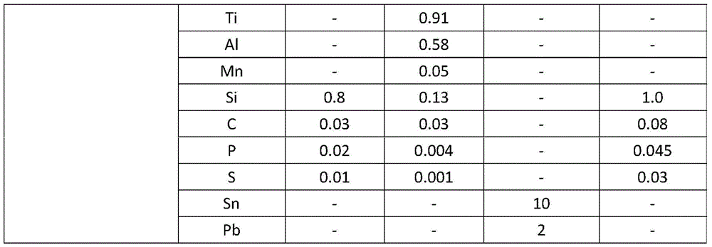
表3:在这个调查中使用的粉末的化学组成和基底Table 3: Chemical compositions and substrates of the powders used in this investigation
实验设定experiment settings
图14示意性地描述根据本发明的示例性实施例的设备。图14示出多种材料SLM系统的示意图。在这个研究中设计并制造了特别的多种材料SLM原型设备(见图14)。x-y-z检流计扫描仪(Nutfield,3XB 3轴)用于在目标粉末床的上方扫掠(scan)具有从500W镱单一模式的、1070nm波长的连续波(CW)光纤激光器(IPG光电,YLR-500-WC)所生成的80μm射束点(beam spot)尺寸的激光束。多粉末传送系统结合了传统的辊子辅助粉末床输送机构和逐点式真空吸盘以及若干个超声粉末分配器,该传统的辊子辅助粉末床输送机构展开主要的构建材料(在这个研究中是316L),该逐点式真空吸盘用于在特定位置处的选择性的、精准的单一层粉末去除,该若干个超声干燥粉末分配器根据设计的形式精确地分别沉积In718和Cu10Sn粉末。超声粉末分配器与真空吸盘(sucker)一起安装在x-y线性平台(stage)。处理操作是在惰性气体环境中,该惰性气体环境充满氮气或氩气,具有氧气水平少于0.3%,其由实时内置氧气传感器监控。在充填惰性气体之前,操作腔室用真空泵抽真空低至40Pa。烟气提取系统构建在系统中,以去除生成的烟气。虽然系统具有内置预加热设施,这在本调查中没有使用。在图14中示出实验性设定的示意图。Fig. 14 schematically depicts an apparatus according to an exemplary embodiment of the present invention. Figure 14 shows a schematic diagram of a multi-material SLM system. A special multi-material SLM prototype device was designed and fabricated in this study (see Figure 14). An x-y-z galvanometer scanner (Nutfield, 3XB 3 axes) was used to sweep (scan) a continuous wave (CW) fiber laser (IPG Optoelectronics, YLR- 500-WC) generated a laser beam with a beam spot size of 80 μm. The multiple powder delivery system combines a traditional roller-assisted powder bed delivery mechanism that spreads out the main build material (316L in this study) with point-by-point vacuum suction cups and several ultrasonic powder distributors. , the point-by-point vacuum chuck is used for selective and precise single-layer powder removal at specific positions, and the several ultrasonic dry powder distributors accurately deposit In718 and Cu10Sn powders respectively according to the designed form. The ultrasonic powder dispenser is mounted on an x-y linear stage together with a sucker. Processing operations are in an inert gas environment filled with nitrogen or argon with an oxygen level of less than 0.3%, which is monitored by a real-time built-in oxygen sensor. Before being filled with inert gas, the operating chamber is evacuated down to 40 Pa with a vacuum pump. A fume extraction system is built into the system to remove the generated fumes. Although the system has a built-in preheating facility, this was not used in this investigation. A schematic diagram of the experimental setup is shown in FIG. 14 .
图15A示意性地描述了根据本发明示例性实施例的增材制造的方法。具体地,图15A示出多种材料SLM的方法流程图。图15A描述了在这个调查中实施的多种材料SLM方法。首先,主粉末材料,即316L,用受监控的辊子和粉末找平刀片在基底上展开50μm厚度的一层。接着,激光束融化期望的区域。选择性的粉末去除处理接着发生以去除在限定的区域中的单一层厚度的粉末,使用真空吸盘。第二/第三材料粉末(In718/Cu10Sn)接着使用超声粉末分配器分配至真空抽吸区域并且接着通过激光束融化并且与已经融化的区域结合。最终,构建平台向下移动等于层厚度的距离。重复以上所有的6个步骤直到制造出这个3D模型。Fig. 15A schematically depicts a method of additive manufacturing according to an exemplary embodiment of the present invention. Specifically, Figure 15A shows a flow diagram of a method for multi-material SLM. Figure 15A depicts the multi-material SLM approach implemented in this investigation. First, the primary powder material, i.e. 316L, is spread in a layer of 50μm thickness on the substrate with monitored rollers and powder leveling blades. Next, the laser beam melts the desired area. A selective powder removal process then occurs to remove a single layer thickness of powder in defined areas, using vacuum chucks. The second/third material powder (In718/Cu10Sn) is then dispensed to the vacuum suction area using an ultrasonic powder dispenser and then melted by the laser beam and bonded to the already melted area. Eventually, the build platform moves down a distance equal to the thickness of the layer. Repeat all 6 steps above until the 3D model is produced.
图15B描述了通过根据图14的设备沉积的第二材料和第一材料的光学照片。具体地,图15B示出了在熔合前,通过在316L粉末层上的超声沉积和选择性粉末真空抽吸所产生的半阴阳图形和Cu10Sn盒。图15B展示了在激光熔合前,通过在316L粉末床层上的超声沉积(Cu10Sn)和选择性粉末真空抽吸所产生的初步实验性的样本。由于真空抽吸喷嘴的扩大区域的宽度大于工具路径补偿值,有一些边界靠近如通过红色箭头所指示的边缘。这样的问题通过在下面的实验中的真空抽吸工具路径优化而解决。FIG. 15B depicts an optical photograph of the second material and the first material deposited by the apparatus according to FIG. 14 . In particular, Figure 15B shows a semi-yin-yang pattern and Cu10Sn cells produced by ultrasonic deposition and selective powder vacuum suction on a 316L powder bed prior to fusion. Figure 15B shows a preliminary experimental sample produced by ultrasonic deposition (Cu10Sn) on a 316L powder bed and selective powder vacuum suction prior to laser fusion. Since the width of the enlarged area of the vacuum suction nozzle is larger than the toolpath offset value, there are some borders close to the edge as indicated by the red arrow. Such issues are addressed by vacuum suction tool path optimization in the following experiments.
图16更详细地示意性地描述了根据图11的增材制造的方法的一部分。因为对于多材料SLM而言没有软件工具,开发了新的数据准备程序和工具。如在图16中所示,多材料部件被认为是组件,包括一组单一材料零件(parts)。为了增强结合,所有这些零件用特别的特征设计在材料界面(interface)上。接着它们组装在一起成为单一部件。在SLM方法数据准备阶段,所有单独材料的几何结构被传送至STL格式(format)中。在用于每个材料的所有STL文档组装在一起之后,接着创建整体支承结构。随后,分别发生用于每个材料的分割(slicing)和填充(hatching)并且结果被输出至激光控制系统。用于选择性的粉末真空去除和超声粉末沉积的工具路径和CNC G代码通过专有的CNC CAM软件工具准备。在表4中呈现用于熔合在这个调查中使用的3种材料的激光处理参数。这些是从许多实验中获得,以达到最佳的融化质量和处理效率。FIG. 16 schematically depicts a part of the method of additive manufacturing according to FIG. 11 in more detail. Because there were no software tools for multi-material SLM, new data preparation procedures and tools were developed. As shown in Figure 16, a multi-material part is considered an assembly comprising a set of single material parts. All of these parts are designed with special features at the material interface for enhanced bonding. They are then assembled together into a single component. During the data preparation phase of the SLM method, the geometries of all individual materials are transferred in STL format. After all the STL files for each material are assembled together, the overall support structure is then created. Subsequently, slicing and hatching for each material occurs separately and the results are output to the laser control system. Toolpaths and CNC G-code for selective powder vacuum removal and ultrasonic powder deposition are prepared through proprietary CNC CAM software tools. The laser processing parameters used to fuse the 3 materials used in this investigation are presented in Table 4. These were obtained from many experiments to achieve the best melting quality and processing efficiency.
表4:用于多材料SLM最佳激光处理参数Table 4: Optimal laser processing parameters for multi-material SLM
材料表征Material Characterization
SLM部分的横截面通过切割、安装、用400#,800#,1000#,and 1200#的网格砂纸研磨来准备,并且最终使用1.0μm钻石抛光糊剂。抛光的样本是在10vol.%的草酸溶液中电蚀刻。材料界面的光学显微图像使用莱卡(Leica)DM2700-M显微镜来获得。Durascan-80硬度测试仪用于测量在样本上的维式显微硬度,该样本具有在Cu10Sn上的0.3kgf施加的负载和在316L/In718部分上的0.5kgf施加负载。使用扫描电子显微镜(SEM,Zeiss Sigma VP FEGSEM)检查在316L/In718和316L/Cu10Sn之间的界面,该扫描电子显微镜装备有用于元素映射的能量色散谱(EDS,牛津仪器X-maxN 150)。The cross section of the SLM part was prepared by cutting, mounting, grinding with 400#, 800#, 1000#, and 1200# grid sandpaper, and finally using 1.0 μm diamond polishing paste. The polished samples were electroetched in 10vol.% oxalic acid solution. Optical microscopic images of material interfaces were obtained using a Leica DM2700-M microscope. A Durascan-80 hardness tester was used to measure the Vickers microhardness on samples with an applied load of 0.3 kgf on the Cu10Sn and 0.5 kgf on the 316L/In718 part. The interface between 316L/In718 and 316L/Cu10Sn was examined using a scanning electron microscope (SEM, Zeiss Sigma VP FEGSEM) equipped with energy dispersive spectroscopy (EDS, Oxford Instruments X-maxN 150) for elemental mapping.
实验结果Experimental results
图17A示意性地描述了通过根据图14的设备沉积的第一材料和第二材料,以及图17B至17C描述了通过根据图14的设备沉积的第一材料和第二材料的光学照片。具体地,图17A至17C示出实验性样本以研究多材料界面:图17A示出“图交叉(figure-cross)”双材料界面的示意;以及图17B和17C分别是方法了的20x 20mm 316L/In718和316L/Cu10Sn样本的顶视图。打印具有4mm宽度的“插指”连结器区域的特定的20x 20平方毫米多层样本,以调查如用于316L/In718和316L/Cu10Sn双材料样本(图17B和17C)的图17A中所示的多材料界面。17A schematically depicts a first material and a second material deposited by the apparatus according to FIG. 14 , and FIGS. 17B to 17C depict optical photographs of the first material and the second material deposited by the apparatus according to FIG. 14 . Specifically, Figures 17A to 17C show experimental samples to study multi-material interfaces: Figure 17A shows a schematic of a "figure-cross" dual-material interface; and Figures 17B and 17C are
图18A至18B更详细地分别描述了图17B和图17C的第一材料和第二材料的光学照片。具体地,图18至18B示出多材料界面的光学显微图像:图18A示出远离基底的316L/In718界面;以及图18B示出靠近基底的316L/Cu10Sn界面。在图18A至18B中示出多材料界面的横截面图的光学显微图像,在图18A至18B中,在图18A中的超声沉积粉末区域中发现了一些孔隙。图18B呈现了在304SS基底、316LSS层、和Cu10Sn层之间的良好的结合。还有Cu渗透至之前融化的316L层的证据(见在图18B中通过箭头所指的位置)。Figures 18A to 18B depict optical photographs of the first and second materials of Figures 17B and 17C, respectively, in more detail. Specifically, Figures 18 to 18B show optical microscopic images of multi-material interfaces: Figure 18A shows a 316L/In718 interface away from the substrate; and Figure 18B shows a 316L/Cu10Sn interface close to the substrate. Optical micrographs of cross-sectional views of the multi-material interface are shown in Figures 18A to 18B where some porosity was found in the region of the ultrasonically deposited powder in Figure 18A. Figure 18B exhibits good bonding between the 304SS substrate, 316LSS layer, and Cu10Sn layer. There is also evidence of Cu penetration into the previously melted 316L layer (see location indicated by arrows in Figure 18B).
图19A描述了图18A的第一材料和第二材料的扫描电子显微镜(SEM)图像,以及图19B至图19D描述了图19A的第一材料和第二材料的能量色散谱(EDS)图像。具体地,图19A至19D示出316L-In718界面的SEM图像和EDS映射。图19A示出316L-In718界面的SEM图像;图19B示出316-In718界面的EDS映射;图19C和图19D分别示出316L-In718界面的Fe和Ni映射。图19A呈现在图19A中所描述的区域的SEM图像,在其中,观察到一些裂缝。EDS映射结果(图19B至19D)示出:大多数这样的缺陷分布在通过超声喷嘴沉积的、由红色箭头指示的In718合金粉末区域中。还发现如图19B中的椭圆形区域中所示的一些316L/In718中间混合区域。合适的材料矩阵将能够实现较低的重量体积比率,以及较高的硬度或韧度。在之前的研究中,预混合材料用于来实现这点,而我们的研究显示材料可以在期望的区域中混合以实现所需的过渡(transition)性质。Figure 19A depicts a scanning electron microscope (SEM) image of the first and second materials of Figure 18A, and Figures 19B-19D depict energy dispersive spectroscopy (EDS) images of the first and second materials of Figure 19A. Specifically, Figures 19A to 19D show SEM images and EDS maps of the 316L-In718 interface. Figure 19A shows the SEM image of the 316L-In718 interface; Figure 19B shows the EDS mapping of the 316-In718 interface; Figure 19C and Figure 19D show the Fe and Ni maps of the 316L-In718 interface, respectively. Figure 19A presents a SEM image of the area depicted in Figure 19A, where some cracks were observed. The EDS mapping results ( FIGS. 19B to 19D ) show that most of such defects are distributed in the region of the In718 alloy powder deposited by the ultrasonic nozzle indicated by the red arrow. Some 316L/In718 intermixed regions were also found as shown in the oval region in Figure 19B. A suitable material matrix will enable lower weight-to-volume ratios, as well as higher stiffness or toughness. In previous studies, premixed materials were used to achieve this, whereas our research shows that materials can be mixed in desired regions to achieve desired transition properties.
图20A描述了图18B的第一材料和第二材料的扫描电子显微镜(SEM)图像,以及图20B至20F描述了图20A的第一材料和第二材料的对应的能量色散谱(EDS)图像。具体地,图20A至20F示出了316L-Cu10Sn界面的SEM图像和EDS映射。图20A示出316L-Cu10Sn界面的SEM图像;图20B示出316L-Cu10Sn界面的EDS映射;以及图20C至20F分别示出316L-Cu10Sn界面的Fe、Sn、Ni和Cu映射。316L/Cu10Sn样品的SEM评估(图20A)揭示在316L和304基底之间的界面和316L/Cu10Sn界面处的良好的冶金结合。随着通过粉末扩展辊子增加层,在熔合的316L区域中没有明显的缺陷呈现。另一方面,在由箭头指示的超声分配的Cu10Sn粉末区域中观察到一些多孔和裂缝。此外,如通过在图20A中的矩形所标记的,一些孤立的光区呈现在316L粉末区域中。进一步的EDS检查(图20F)示出如Cu这样的区域的化学组成,指示Cu元素扩散至Fe区域中。通过比较图20C和图20F,在扫描了的区域的右上角中发现双粉末校对区域。这可能是因为不充分的316L粉末真空去除。一些316L粉末的残余与沉积的Cu10Sn粉末搅拌,并且通过后续的激光熔合方法而熔合。Figure 20A depicts a scanning electron microscope (SEM) image of the first and second materials of Figure 18B, and Figures 20B to 20F depict corresponding energy dispersive spectroscopy (EDS) images of the first and second materials of Figure 20A . Specifically, FIGS. 20A to 20F show SEM images and EDS maps of the 316L-Cu10Sn interface. Figure 20A shows the SEM image of the 316L-Cu10Sn interface; Figure 20B shows the EDS mapping of the 316L-Cu10Sn interface; and Figures 20C to 20F show the Fe, Sn, Ni and Cu maps of the 316L-Cu10Sn interface, respectively. SEM evaluation of the 316L/Cu10Sn sample (FIG. 20A) revealed good metallurgical bonding at the interface between the 316L and 304 substrates and at the 316L/Cu10Sn interface. No apparent defects appeared in the fused 316L regions as the layers were added through the powder expanding rolls. On the other hand, some porosity and cracks were observed in the ultrasonically dispensed Cu10Sn powder regions indicated by arrows. In addition, some isolated regions of light are present in the 316L powder regions, as marked by the rectangles in Figure 20A. Further EDS inspection (FIG. 20F) showed the chemical composition of the regions as Cu, indicating Cu elemental diffusion into the Fe regions. By comparing Figure 2OC and Figure 2OF, a double powder proofing area is found in the upper right corner of the scanned area. This may be due to insufficient vacuum removal of the 316L powder. Some remnants of 316L powder were stirred with deposited Cu10Sn powder and fused by subsequent laser fusion method.
图21描述了图17B和17C的第一材料和第二材料的维氏硬度的曲线图。具体地,图21示出SLM 316L/In718样本和SLM 316L/Cu10Sn样本的水平方向的维氏硬度。沿着双材料制成的SLM样本的水平方向的维氏硬度值在图21中示出。可以知道,316L部分的硬度值的范围从237±6HV至251±4HV,以及In718部分的硬度值的范围从301±4HV至310±6HV,其中过渡区域具有在两个材料的硬度值之间的硬度值。在316L/Cu10Sn样本上的316L和Cu10Sn的硬度值分别是227±7HV至247±8HV以及149±8HV至160±6HV,同时在过渡区域中的硬度值的范围是在两个材料的硬度值之间。由于特别的“插指”连结器结构设计,可以实现更好的材料元素扩散和结合。应注意的是,如在两个曲线中都示出,在过滤区域中的微硬度标准偏差的值比在单一材料区域中的微硬度标准偏差的值高很多。21 depicts a graph of the Vickers hardness of the first and second materials of FIGS. 17B and 17C. Specifically, FIG. 21 shows the Vickers hardness in the horizontal direction of the
图22A至22C描述了通过根据图14的设备沉积的第一材料和第二材料的光学照片。具体地,图22A示出包括3个材料的袖珍房屋;图22B示出狮身人面像的多颜色、多材料雕塑;以及图22C示出双色网格图形。为了展示使用SLM的3D多材料打印,使用专用系统制造一组3D复杂的形状。如在图22A中所示,简单的房屋的门阶和烟囱分别是由Cu10Sn和In718支撑的,而房屋的其他部分是由316L材料制成的。在图22B和22C中,金色和银色分别代表Cu10Sn和316L材料。应注意的是,狮身人面像的蛇头饰(图22B)是使用局部粉末混合策略由316L/Cu10Sn材料矩阵制成,而脸是由Cu10Sn制成以及其余的是由316L不锈钢制成。如在图22C中所示的薄壁结构和光斑直径分别是厚度上为150μm以及直径上是1mm。22A to 22C depict optical photographs of a first material and a second material deposited by the apparatus according to FIG. 14 . Specifically, Figure 22A shows a pocket house comprising 3 materials; Figure 22B shows a multi-color, multi-material sculpture of a sphinx; and Figure 22C shows a two-color grid pattern. To demonstrate 3D multi-material printing using SLM, a set of 3D complex shapes were fabricated using a dedicated system. As shown in Fig. 22A, the doorstep and chimney of a simple house are supported by Cu10Sn and In718, respectively, while the rest of the house is made of 316L material. In Figures 22B and 22C, gold and silver colors represent Cu10Sn and 316L materials, respectively. It should be noted that the snake headdress of the Sphinx (FIG. 22B) was made of 316L/Cu10Sn material matrix using a localized powder mixing strategy, while the face was made of Cu10Sn and the rest was made of 316L stainless steel. The thin-walled structure and spot diameter as shown in FIG. 22C are 150 μm in thickness and 1 mm in diameter, respectively.
图23示意性地描述根据本发明的示例性实施方式的设备的一部分。具体地,图23示出在这个工作中使用的选择性地烘干粉末分配器。在用于多材料的3D打印的混合粉末床和超声喷嘴粉末输送系统中,小的超声输送漏斗和喷嘴的使用将使材料送料的高分辨率和稳定性成为可能,然后,它仅能持续很短的时间段,因此不适合用于打印大的零件。如图23中所示的级联的粉末输送系统使得精确和稳定的粉末输送和粉末材料供应成为可能,以允许大的组分的打印。次级粉末供应系统是压力气体驱动的粉末储存单元并且与超声分配器一体。自动气动点胶控制器允许连续的或非连续定时地(timed)将粉末供应至分配桶。根据申请需要,粉末可以是金属的、陶瓷的或聚合物类型或它们的混合物。Fig. 23 schematically depicts a part of an apparatus according to an exemplary embodiment of the present invention. Specifically, Figure 23 shows the selectively dryable powder dispenser used in this work. In the mixed powder bed and ultrasonic nozzle powder delivery system for multi-material 3D printing, the use of small ultrasonic delivery funnel and nozzle will enable the high resolution and stability of material feeding, then, it can only last for a long time Short time periods and therefore not suitable for printing large parts. A cascaded powder delivery system as shown in Figure 23 enables precise and steady powder delivery and powder material supply to allow printing of large components. The secondary powder supply system is a pressurized gas powered powder storage unit and is integrated with the ultrasonic dispenser. The automatic pneumatic dispensing controller allows continuous or non-continuous timed supply of powder to the dispensing barrel. Depending on the needs of the application, the powder can be of metallic, ceramic or polymeric type or mixtures thereof.
这个工作展示多材料SLM技术,通过第一次将传统的粉末床展开(spreading)与逐点式多材料选择性粉末去除和烘干粉末输送。专业实验性SLM设备和特别的用于SLM的多材料CAD数据准备被研发并应用以成功地生产316L/In718和316L/Cu10Sn样本。通过实验结果确认了将多种材料沉积在相同的构建层上并穿越不同的层的可行性。在用于材料组合研究的材料界面处获得清晰的夹层分布和良好的冶金结合。结果还指示特别的材料界面设计对于增强材料元素扩散,其导致更好的结合。在另一方面,由于不均匀的粉末分配在超声地沉积的粉末区域发现一些包括孔和裂缝的缺陷。具体地,这个工作显示了多材料SLM的新方法,其通过将粉末床展开、逐点式多喷嘴超声烘干粉末输送以及逐点式单一层粉末去除结合在一起以实现在相同层内的多材料熔合和穿过不同层来打印多金属3D组分。This work demonstrates multi-material SLM technology by combining traditional powder bed spreading with point-by-point multi-material selective powder removal and dry powder delivery for the first time. Specialized experimental SLM equipment and special multi-material CAD data preparation for SLM were developed and applied to successfully produce 316L/In718 and 316L/Cu10Sn samples. The experimental results confirmed the feasibility of depositing multiple materials on the same build layer and across different layers. Obtain clear interlayer distribution and good metallurgical bonding at material interfaces for material combination studies. The results also indicate that special material interface design is important for enhanced material element diffusion, which leads to better bonding. On the other hand, some defects including holes and cracks were found in the ultrasonically deposited powder area due to uneven powder distribution. Specifically, this work shows a new approach to multi-material SLM by combining powder bed expansion, point-by-point multi-nozzle ultrasonic drying powder delivery, and point-by-point single-layer powder removal to achieve multi-materials within the same layer. Materials fuse and pass through different layers to print multi-metal 3D components.
总的来说,本发明提供了用于增材制造的设备和由包括具有第一组成的颗粒的第一材料制成对制品的一部分进行增材制造的方法。包括具有不同于第一组成的第二组成的颗粒的第二材料提供支承材料,可布置成在例如增材制造的中间阶段期间支承构建材料。第二材料由此可用于在制品和/或制品的一部分的增材制造期间提供支承结构。因为第一组成和第二组成是不同的,它们各自的性质可根据它们各自的用途来选择,由此促进了诸如支承结构的第二材料的去除,同时减少了第一材料的消耗。此外,因此减少了第一材料和第二材料的交叉污染而改进了第一材料和/或第二材料的再使用和再循环。以这种方式,用于制品的一部分的增材制造的设备涉及在第一材料的标准粉末床选择性激光熔化之后,第一材料的每个层中的选择性材料的去除。接着在这之后是第二材料的选择性逐点式粉末或粉末-液体材料沉积,之后是第二材料的选择性激光熔化或连结的其他方式,可选地包括喷射聚合物结合剂。使用所述选择性材料沉积可以将多种材料沉积在每个层中。对于接下来(即:随后的)的层(即:覆盖该层的层)重复进行方法,直到形成完整的制品。以相似的方式可以沉积第三、第四以及更多不同类型的材料。具体地,这允许了在具体的层(即:层内)和/或在连续的层(即:夹层)内形成由多种材料制成的制品,由此增强了以这种方式形成的制品的结构、功能和/或性质。In general, the present invention provides apparatus for additive manufacturing and methods of additively manufacturing a portion of an article from a first material comprising particles having a first composition. The second material comprising particles having a second composition different from the first composition provides a support material which may be arranged to support the build material eg during intermediate stages of additive manufacturing. The second material may thus be used to provide a support structure during additive manufacturing of the article and/or part of the article. Because the first composition and the second composition are different, their respective properties can be selected according to their respective uses, thereby facilitating the removal of the second material, such as the support structure, while reducing the consumption of the first material. Furthermore, re-use and recycling of the first material and/or the second material is thus improved by reducing cross-contamination of the first material and the second material. In this manner, an apparatus for additive manufacturing of a portion of an article involves selective material removal in each layer of a first material following standard powder bed selective laser melting of the first material. This is followed by selective point-by-point powder or powder-liquid material deposition of the second material, followed by selective laser melting or other means of bonding of the second material, optionally including spraying of a polymer binder. Multiple materials can be deposited in each layer using the selective material deposition. The process is repeated for the next (ie, subsequent) layer (ie, the layer covering it) until a complete article is formed. Third, fourth and further different types of materials can be deposited in a similar manner. In particular, this allows for the formation of articles made of multiple materials in specific layers (i.e., within layers) and/or within successive layers (i.e., interlayers), thereby enhancing articles formed in this manner structure, function and/or properties.
注意力应集中于与本说明书一起或在本说明书之前提交的所有与本说明书有关的、以及与本说明书一起开放给公众检查的论文和文件,并且所有这样的论文和文件的内容以参照的形式结合至本文中。在这个说明书中公开的所有的特征(包括任何所附的权利要求和附图),和/或所公开的任何方法或处理方法的所有步骤可以结合在任何组合中,除了(except)在其中至少一些这样的特征和/或步骤是相互排斥的组合。在本说明书中(包括任何所附的权利要求和附图)中所公开的每个特征可以通过用作相同、相等或相似目的的可替代特征来替换,除非另有明确声明。由此,除非另有明确声明,所公开的每个特征仅是相等或相似特征的通用系列得一个示例。本发明不限制于前述实施例得细节。本发明可以扩展至在这个说明书(包括所附的权利要求和附图)中公开的特征的任何新颖的一个特征或任何新颖的组合、或至所公开的任何方法或处理方法的步骤的任何新颖的一个步骤或任何新颖的组合。Attention should be directed to all papers and documents filed with or preceding this specification relating to this specification and open to public inspection with this specification, and the contents of all such papers and documents are incorporated by reference Incorporated into this article. All features disclosed in this specification (including any accompanying claims and drawings), and/or all steps of any method or process disclosed may be combined in any combination, except where at least Some of such features and/or steps are in mutually exclusive combinations. Each feature disclosed in this specification (including any accompanying claims and drawings) may be replaced by alternative features serving the same, equivalent or similar purpose, unless expressly stated otherwise. Thus, unless expressly stated otherwise, each feature disclosed is one example only of a generic series of equivalent or similar features. The invention is not limited to the details of the foregoing examples. The invention extends to any novel one or any novel combination of features disclosed in this specification (including the appended claims and drawings), or to any novel step of any method or process disclosed A step or any novel combination of .
Claims (27)
Applications Claiming Priority (5)
| Application Number | Priority Date | Filing Date | Title |
|---|---|---|---|
| GB1706645.7 | 2017-04-26 | ||
| GBGB1706645.7A GB201706645D0 (en) | 2017-04-26 | 2017-04-26 | Apparatus for and process of additive manufacturing |
| GBGB1800743.5A GB201800743D0 (en) | 2018-01-17 | 2018-01-17 | Apparatus for process of additive manufacturing |
| GB1800743.5 | 2018-01-17 | ||
| PCT/GB2018/051093 WO2018197876A1 (en) | 2017-04-26 | 2018-04-26 | Apparatus for and process of additive manufacturing |
Publications (2)
| Publication Number | Publication Date |
|---|---|
| CN111050954A CN111050954A (en) | 2020-04-21 |
| CN111050954B true CN111050954B (en) | 2023-01-03 |
Family
ID=62111113
Family Applications (1)
| Application Number | Title | Priority Date | Filing Date |
|---|---|---|---|
| CN201880043285.3A Expired - Fee Related CN111050954B (en) | 2017-04-26 | 2018-04-26 | Apparatus and method for additive manufacturing |
Country Status (4)
| Country | Link |
|---|---|
| US (1) | US11583930B2 (en) |
| EP (1) | EP3615248A1 (en) |
| CN (1) | CN111050954B (en) |
| WO (1) | WO2018197876A1 (en) |
Families Citing this family (32)
| Publication number | Priority date | Publication date | Assignee | Title |
|---|---|---|---|---|
| US10520923B2 (en) | 2018-05-22 | 2019-12-31 | Mantle Inc. | Method and system for automated toolpath generation |
| US11118884B2 (en) | 2018-08-21 | 2021-09-14 | Aob Products Company | Dispenser for firearm ammunition powder |
| KR102119452B1 (en) * | 2018-12-28 | 2020-06-05 | 주식회사 성우하이텍 | Layer laminating device and 3d printing method using the same |
| WO2020237165A2 (en) * | 2019-05-23 | 2020-11-26 | General Electric Company | Additive manufacturing apparatuses and methods for using the same |
| US11566878B2 (en) * | 2019-06-17 | 2023-01-31 | Aob Products Company | Dispenser for firearm ammunition powder |
| US20210016392A1 (en) * | 2019-07-15 | 2021-01-21 | Hamilton Sundstrand Corporation | Waste product removal systems |
| RU2732271C1 (en) * | 2019-07-30 | 2020-09-14 | Общество с ограниченной ответственностью Научно-производственный центр "Лазеры и аппаратура ТМ" | Method for layer-by-layer manufacturing of three-dimensional articles |
| RU2734650C1 (en) * | 2019-07-30 | 2020-10-21 | Общество с ограниченной ответственностью Научно-производственный центр "Лазеры и аппаратура ТМ" | Device for layer-by-layer manufacturing of 3d articles and method of production thereof |
| RU2732252C1 (en) * | 2019-07-30 | 2020-09-14 | Общество с ограниченной ответственностью Научно-производственный центр "Лазеры и аппаратура ТМ" | Method for layer-by-layer manufacturing of three-dimensional articles |
| CN110514492B (en) * | 2019-08-02 | 2022-02-08 | 中北大学 | Method for detecting gamma' phase IN selective laser melting forming nickel-based superalloy IN718 |
| US20210229361A1 (en) * | 2020-01-28 | 2021-07-29 | Divergent Technologies, Inc. | 3-d printer with gas exchange mechanism for removing contaminants during re-coating |
| US12337541B2 (en) * | 2020-02-27 | 2025-06-24 | Divergent Technologies, Inc. | Powder bed fusion additive manufacturing system with desiccant positioned within hopper and ultrasonic transducer |
| US11766832B2 (en) | 2020-05-13 | 2023-09-26 | The Boeing Company | System and method for additively manufacturing an object |
| US11590705B2 (en) | 2020-05-13 | 2023-02-28 | The Boeing Company | System and method for additively manufacturing an object |
| CN112404459A (en) * | 2020-11-05 | 2021-02-26 | 阳江市普瑞德增材制造研究院有限公司 | Powder bed melting additive manufacturing equipment and method |
| CN112893764B (en) * | 2021-01-21 | 2022-04-12 | 大连理工大学 | 3D printing coated silica sand for optical fiber laser processing and preparation method thereof |
| JP7346476B2 (en) * | 2021-03-10 | 2023-09-19 | 日本電子株式会社 | 3D additive manufacturing device and 3D additive manufacturing method |
| CN113059195B (en) * | 2021-06-03 | 2021-08-13 | 西安赛隆金属材料有限责任公司 | A powder bed spreading device and powder bed additive manufacturing equipment |
| FR3123815B1 (en) * | 2021-06-15 | 2023-11-24 | Safran Aircraft Engines | Additive manufacturing device |
| US12005648B2 (en) | 2022-01-14 | 2024-06-11 | Sakuu Corporation | Apparatus and method to remove powder with flexible scraper blade and adjustable side nozzles |
| CN114454294B (en) * | 2022-01-20 | 2024-10-18 | 东莞理工学院 | Be used for light-cured 3D printing device of paste material |
| CN114734633A (en) * | 2022-03-31 | 2022-07-12 | 李明 | 3D printer of multi-nozzle type melting technology |
| CN115007877B (en) * | 2022-05-11 | 2024-04-09 | 浙江工业大学 | Additive manufacturing method for realizing selective laser melting of same-layer heterogeneous materials by using mask |
| WO2023235758A1 (en) * | 2022-06-01 | 2023-12-07 | Brian Hachtmann | Methods and systems for three-dimensional printing |
| US20240045398A1 (en) * | 2022-08-02 | 2024-02-08 | Palo Alto Research Center Incorporated | Techniques to determine a hybrid manufacturing plan |
| CN115740499B (en) * | 2022-11-24 | 2025-06-10 | 北京工业大学 | A method for 3D printing of nickel-based high-temperature alloy/copper alloy dissimilar metal components |
| US12263639B2 (en) | 2022-12-02 | 2025-04-01 | Sakuu Corporation | Apparatus and method to remove powder with flexible scraper blade and adjustable side nozzles |
| DE102022135018A1 (en) * | 2022-12-29 | 2024-07-04 | Nikon Slm Solutions Ag | TECHNIQUE FOR TEMPERATURE CONTROL OF A THREE-DIMENSIONAL WORKPIECE PRODUCED BY ADDITIVE MANUFACTURING |
| CN115871219B (en) * | 2023-03-08 | 2023-06-20 | 成都航空职业技术学院 | A kind of coloring component and 3D printer for 3D printer |
| CN116890125B (en) * | 2023-06-09 | 2025-09-30 | 佛山市激创智造智能装备有限公司 | An in-situ stress measurement device and method for laser selective melting of multi-material interfaces |
| US12528249B2 (en) | 2024-04-12 | 2026-01-20 | General Electric Company | Powder removal apparatuses for additive manufacturing apparatuses |
| CN119426619B (en) * | 2024-09-03 | 2026-01-16 | 湖南华曙高科技股份有限公司 | Support design method for 3D printing and 3D printing method |
Family Cites Families (15)
| Publication number | Priority date | Publication date | Assignee | Title |
|---|---|---|---|---|
| DE4216502C1 (en) | 1992-05-19 | 1993-11-04 | Eos Electro Optical Syst | Objects made of light hardening polymer - are built up in thin successive layers using optically etched film moulds which are melted out after use |
| US6363606B1 (en) * | 1998-10-16 | 2002-04-02 | Agere Systems Guardian Corp. | Process for forming integrated structures using three dimensional printing techniques |
| DE19935274C1 (en) * | 1999-07-27 | 2001-01-25 | Fraunhofer Ges Forschung | Apparatus for producing components made of a material combination has a suction and blowing device for removing material from the processing surface, and a feed device for a further material |
| DE10058748C1 (en) | 2000-11-27 | 2002-07-25 | Markus Dirscherl | Method for producing a component and device for carrying out the method |
| GB0821660D0 (en) * | 2008-11-27 | 2008-12-31 | Univ Exeter The | Manufacturing device and method |
| WO2015151834A1 (en) * | 2014-03-31 | 2015-10-08 | 独立行政法人産業技術総合研究所 | Three-dimensional fabrication apparatus |
| JP2017524579A (en) | 2014-05-04 | 2017-08-31 | エオプレックス・リミテッドEoplex Limited | Multi-material 3D printer |
| EP3157696A4 (en) * | 2014-06-20 | 2018-09-05 | VELO3D, Inc. | Apparatuses, systems and methods for three-dimensional printing |
| US9427773B2 (en) * | 2014-08-25 | 2016-08-30 | Solidscape, Inc. | Method for simultaneously scribing and filling of scribed channel, trough, trench or groove |
| CN204639130U (en) * | 2014-12-12 | 2015-09-16 | 华南理工大学 | The equipment of the fusing of a kind of single casing selective laser and milling Compound Machining |
| CN105383059B (en) * | 2015-12-02 | 2018-06-01 | 吉林大学 | More material powderings and molding 3D printing method and printing equipment |
| GB2548340A (en) | 2016-03-09 | 2017-09-20 | Digital Metal Ab | Manufacturing method and manufacturing apparatus |
| CN105945282B (en) * | 2016-05-23 | 2019-04-02 | 苏州云植医学技术有限公司 | Special selective laser melting equipment for directly manufacturing metal orthopedic implant |
| EP3338916A1 (en) * | 2016-12-22 | 2018-06-27 | HILTI Aktiengesellschaft | Method for layerwise manufacturing of a component made of powdery material |
| US10343214B2 (en) * | 2017-02-17 | 2019-07-09 | General Electric Company | Method for channel formation in binder jet printing |
-
2018
- 2018-04-26 CN CN201880043285.3A patent/CN111050954B/en not_active Expired - Fee Related
- 2018-04-26 US US16/608,735 patent/US11583930B2/en active Active
- 2018-04-26 EP EP18722159.3A patent/EP3615248A1/en not_active Withdrawn
- 2018-04-26 WO PCT/GB2018/051093 patent/WO2018197876A1/en not_active Ceased
Also Published As
| Publication number | Publication date |
|---|---|
| WO2018197876A1 (en) | 2018-11-01 |
| EP3615248A1 (en) | 2020-03-04 |
| CN111050954A (en) | 2020-04-21 |
| US11583930B2 (en) | 2023-02-21 |
| US20210094102A1 (en) | 2021-04-01 |
Similar Documents
| Publication | Publication Date | Title |
|---|---|---|
| CN111050954B (en) | Apparatus and method for additive manufacturing | |
| Wei et al. | 3D printing of multiple metallic materials via modified selective laser melting | |
| Wang et al. | Review of additive manufacturing methods for high-performance ceramic materials | |
| CN112384317A (en) | Powder deposition | |
| CN110337347B (en) | Metal bond abrasive article and method of making a metal bond abrasive article | |
| US11420254B2 (en) | Method of forming an object using 3D printing | |
| CN101068503B (en) | Method for forming a green body and articles made by the method | |
| US20160157963A1 (en) | Methods for shaping green bodies and articles made by such methods | |
| WO2017120279A1 (en) | Materials and formulations for three-dimensional printing | |
| US20210016501A1 (en) | Devices, systems and methods for printing three-dimensional objects | |
| US20190240734A1 (en) | Geometry For Debinding 3D Printed Parts | |
| EP0610442A1 (en) | Multiple powder delivery for selective laser sintering | |
| FR3070134B1 (en) | METHOD AND MACHINE FOR MANUFACTURING AT LEAST ONE PIECE OF AT LEAST ONE CERAMIC AND / OR METALLIC MATERIAL BY THE TECHNIQUE OF ADDITIVE PROCESSES | |
| US11202694B2 (en) | Method of making a dental articles | |
| CN106827508A (en) | The manufacture method of three-D moulding object and the manufacture device of three-D moulding object | |
| Wang et al. | Recent advances on additive manufacturing of heterogeneous/gradient metallic materials via laser powder bed fusion | |
| JP2025506753A (en) | Recyclable metal composite sheet, its use and manufacturing method | |
| US20180304353A1 (en) | Structural support for 3d printer gantry | |
| RU2318638C2 (en) | Electrode for electro-discharge treatment of the surface, mode of estimation of the electrode and the mode of electro-discharge treatment of the surface | |
| JP2019023327A (en) | Method and device for manufacturing a lamination molded object | |
| Peyre et al. | Additive manufacturing of metal alloys 1: processes, raw materials and numerical simulation | |
| Thompson et al. | Process Defects in Metal Additive Manufacturing | |
| WO2020091773A1 (en) | Sinterable setter with interface layer | |
| Chen | Ceramic powder-based hybrid binder jetting system | |
| JP7234716B2 (en) | Powder for three-dimensional modeling, container containing powder, method for producing three-dimensional model, and apparatus for producing three-dimensional model |
Legal Events
| Date | Code | Title | Description |
|---|---|---|---|
| PB01 | Publication | ||
| PB01 | Publication | ||
| SE01 | Entry into force of request for substantive examination | ||
| SE01 | Entry into force of request for substantive examination | ||
| GR01 | Patent grant | ||
| GR01 | Patent grant | ||
| CF01 | Termination of patent right due to non-payment of annual fee | ||
| CF01 | Termination of patent right due to non-payment of annual fee |
Granted publication date: 20230103 |