CN111050680A - Variable Phase Generation and Detection for Radio Frequency (RF) Ablation - Google Patents
Variable Phase Generation and Detection for Radio Frequency (RF) Ablation Download PDFInfo
- Publication number
- CN111050680A CN111050680A CN201880058029.1A CN201880058029A CN111050680A CN 111050680 A CN111050680 A CN 111050680A CN 201880058029 A CN201880058029 A CN 201880058029A CN 111050680 A CN111050680 A CN 111050680A
- Authority
- CN
- China
- Prior art keywords
- ablation
- replicas
- signal
- phase
- electrodes
- Prior art date
- Legal status (The legal status is an assumption and is not a legal conclusion. Google has not performed a legal analysis and makes no representation as to the accuracy of the status listed.)
- Granted
Links
Images


Classifications
-
- A—HUMAN NECESSITIES
- A61—MEDICAL OR VETERINARY SCIENCE; HYGIENE
- A61B—DIAGNOSIS; SURGERY; IDENTIFICATION
- A61B18/00—Surgical instruments, devices or methods for transferring non-mechanical forms of energy to or from the body
- A61B18/04—Surgical instruments, devices or methods for transferring non-mechanical forms of energy to or from the body by heating
- A61B18/12—Surgical instruments, devices or methods for transferring non-mechanical forms of energy to or from the body by heating by passing a current through the tissue to be heated, e.g. high-frequency current
- A61B18/1206—Generators therefor
-
- A—HUMAN NECESSITIES
- A61—MEDICAL OR VETERINARY SCIENCE; HYGIENE
- A61B—DIAGNOSIS; SURGERY; IDENTIFICATION
- A61B18/00—Surgical instruments, devices or methods for transferring non-mechanical forms of energy to or from the body
- A61B18/04—Surgical instruments, devices or methods for transferring non-mechanical forms of energy to or from the body by heating
- A61B18/12—Surgical instruments, devices or methods for transferring non-mechanical forms of energy to or from the body by heating by passing a current through the tissue to be heated, e.g. high-frequency current
- A61B18/14—Probes or electrodes therefor
- A61B18/1492—Probes or electrodes therefor having a flexible, catheter-like structure, e.g. for heart ablation
-
- A—HUMAN NECESSITIES
- A61—MEDICAL OR VETERINARY SCIENCE; HYGIENE
- A61B—DIAGNOSIS; SURGERY; IDENTIFICATION
- A61B18/00—Surgical instruments, devices or methods for transferring non-mechanical forms of energy to or from the body
- A61B2018/00053—Mechanical features of the instrument of device
- A61B2018/0016—Energy applicators arranged in a two- or three dimensional array
-
- A—HUMAN NECESSITIES
- A61—MEDICAL OR VETERINARY SCIENCE; HYGIENE
- A61B—DIAGNOSIS; SURGERY; IDENTIFICATION
- A61B18/00—Surgical instruments, devices or methods for transferring non-mechanical forms of energy to or from the body
- A61B2018/00636—Sensing and controlling the application of energy
- A61B2018/00642—Sensing and controlling the application of energy with feedback, i.e. closed loop control
- A61B2018/00654—Sensing and controlling the application of energy with feedback, i.e. closed loop control with individual control of each of a plurality of energy emitting elements
-
- A—HUMAN NECESSITIES
- A61—MEDICAL OR VETERINARY SCIENCE; HYGIENE
- A61B—DIAGNOSIS; SURGERY; IDENTIFICATION
- A61B18/00—Surgical instruments, devices or methods for transferring non-mechanical forms of energy to or from the body
- A61B2018/00636—Sensing and controlling the application of energy
- A61B2018/00696—Controlled or regulated parameters
- A61B2018/00714—Temperature
-
- A—HUMAN NECESSITIES
- A61—MEDICAL OR VETERINARY SCIENCE; HYGIENE
- A61B—DIAGNOSIS; SURGERY; IDENTIFICATION
- A61B18/00—Surgical instruments, devices or methods for transferring non-mechanical forms of energy to or from the body
- A61B2018/00636—Sensing and controlling the application of energy
- A61B2018/00696—Controlled or regulated parameters
- A61B2018/00732—Frequency
-
- A—HUMAN NECESSITIES
- A61—MEDICAL OR VETERINARY SCIENCE; HYGIENE
- A61B—DIAGNOSIS; SURGERY; IDENTIFICATION
- A61B18/00—Surgical instruments, devices or methods for transferring non-mechanical forms of energy to or from the body
- A61B2018/00636—Sensing and controlling the application of energy
- A61B2018/00696—Controlled or regulated parameters
- A61B2018/0075—Phase
-
- A—HUMAN NECESSITIES
- A61—MEDICAL OR VETERINARY SCIENCE; HYGIENE
- A61B—DIAGNOSIS; SURGERY; IDENTIFICATION
- A61B18/00—Surgical instruments, devices or methods for transferring non-mechanical forms of energy to or from the body
- A61B2018/00636—Sensing and controlling the application of energy
- A61B2018/00773—Sensed parameters
- A61B2018/00827—Current
-
- A—HUMAN NECESSITIES
- A61—MEDICAL OR VETERINARY SCIENCE; HYGIENE
- A61B—DIAGNOSIS; SURGERY; IDENTIFICATION
- A61B18/00—Surgical instruments, devices or methods for transferring non-mechanical forms of energy to or from the body
- A61B2018/00636—Sensing and controlling the application of energy
- A61B2018/00773—Sensed parameters
- A61B2018/00869—Phase
-
- A—HUMAN NECESSITIES
- A61—MEDICAL OR VETERINARY SCIENCE; HYGIENE
- A61B—DIAGNOSIS; SURGERY; IDENTIFICATION
- A61B18/00—Surgical instruments, devices or methods for transferring non-mechanical forms of energy to or from the body
- A61B2018/00636—Sensing and controlling the application of energy
- A61B2018/00773—Sensed parameters
- A61B2018/00892—Voltage
-
- A—HUMAN NECESSITIES
- A61—MEDICAL OR VETERINARY SCIENCE; HYGIENE
- A61B—DIAGNOSIS; SURGERY; IDENTIFICATION
- A61B18/00—Surgical instruments, devices or methods for transferring non-mechanical forms of energy to or from the body
- A61B18/04—Surgical instruments, devices or methods for transferring non-mechanical forms of energy to or from the body by heating
- A61B18/12—Surgical instruments, devices or methods for transferring non-mechanical forms of energy to or from the body by heating by passing a current through the tissue to be heated, e.g. high-frequency current
- A61B18/1206—Generators therefor
- A61B2018/124—Generators therefor switching the output to different electrodes, e.g. sequentially
-
- A—HUMAN NECESSITIES
- A61—MEDICAL OR VETERINARY SCIENCE; HYGIENE
- A61B—DIAGNOSIS; SURGERY; IDENTIFICATION
- A61B18/00—Surgical instruments, devices or methods for transferring non-mechanical forms of energy to or from the body
- A61B18/04—Surgical instruments, devices or methods for transferring non-mechanical forms of energy to or from the body by heating
- A61B18/12—Surgical instruments, devices or methods for transferring non-mechanical forms of energy to or from the body by heating by passing a current through the tissue to be heated, e.g. high-frequency current
- A61B18/1206—Generators therefor
- A61B2018/1273—Generators therefor including multiple generators in one device
Landscapes
- Health & Medical Sciences (AREA)
- Surgery (AREA)
- Engineering & Computer Science (AREA)
- Life Sciences & Earth Sciences (AREA)
- Biomedical Technology (AREA)
- Molecular Biology (AREA)
- Nuclear Medicine, Radiotherapy & Molecular Imaging (AREA)
- Plasma & Fusion (AREA)
- Physics & Mathematics (AREA)
- Heart & Thoracic Surgery (AREA)
- Medical Informatics (AREA)
- Otolaryngology (AREA)
- Animal Behavior & Ethology (AREA)
- General Health & Medical Sciences (AREA)
- Public Health (AREA)
- Veterinary Medicine (AREA)
- Cardiology (AREA)
- Surgical Instruments (AREA)
Abstract
A Radio Frequency (RF) ablation system includes a signal generator, a control circuit, a plurality of non-linear amplifiers, and a processor. The signal generator is configured to generate an RF signal having a given frequency. The control circuit is configured to set the phase and amplitude of the multiple replicas of the RF signal generated by the signal generator. The plurality of non-linear amplifiers are configured to amplify the plurality of replicas of the RF signal and drive a corresponding plurality of ablation electrodes in a patient's body with the amplified replicas. The processor is configured to receive a return signal comprising a superposition of the replicas sensed by patch electrodes attached to the patient's body, and to adaptively adjust the phase and amplitude of the replicas in response to the return signal by controlling the control circuitry.
Description
Technical Field
The present invention relates generally to the design of ablation systems, and in particular to the design of multi-electrode cardiac ablation systems.
Background
Various known invasive medical device designs use multiple electrodes to apply ablative Radio Frequency (RF) energy to tissue of a patient. For example, U.S. patent application publication 2015/0272655 describes a system and method for preventing unintended tissue damage due to unintended delivery of bipolar RF energy. The system may include a multi-electrode ablation device and an RF delivery unit. The RF delivery unit may deliver unipolar energy to a plurality of electrodes, the energy being in phase, wherein all electrodes deliver the same voltage and are activated simultaneously to not deliver bipolar energy. Additionally or alternatively, the RF delivery unit may deliver bipolar energy to the electrodes. Here, the voltage difference between each pair of adjacent electrodes may be monitored and the level of bipolar energy delivered may be calculated. The voltage of the energy delivered to at least one electrode of each adjacent electrode pair may be adjusted if the amount of bipolar energy delivered exceeds a safety threshold.
As another example, U.S. patent 5,383,917 describes multi-phased RF ablation using a two-or three-dimensional electrode array that creates multiple current paths on the surface of the ablation zone. This results in a uniform lesion whose size is defined by the span of the electrode array. An orthogonal electrode catheter array suitable for cardiac ablation is used in conjunction with a two-phase RF power source to create a uniform square lesion. Larger sized lesions are created by the continuous adjacent placement of square lesions. Temperature sensors at the electrode tip allow monitoring and adjustment of the ablation temperature to minimize contamination of the electrode tip with coagulum.
Us patent 6,059,778 describes a device for delivering energy to a biological site. The apparatus includes an electrode arrangement having a plurality of electrodes, the electrode arrangement positioned proximal to the biological site. The power control system provides power to each of the electrodes with a controllable phase angle. The backing plate is also positioned proximal to the biological site such that the biological site is interposed between the electrode device and the backing plate. The back plate is held at a reference voltage level with respect to power. The power control system controls the phase angle of the power so that the current flow between the electrodes and the backing plate results in the desired continuity and depth of ablation. In a preferred embodiment, the electrodes are arranged in a substantially linear array.
Us patent 6,050,994 describes an apparatus for delivering energy to a biological site, the apparatus comprising a catheter having a plurality of electrodes. The power control system provides power signals to each of the electrodes each having a controllable phase angle such that the phase alternates between the electrodes. The duty cycle of each electrode is controlled and during the off period of the duty cycle, the phase angles of adjacent electrodes are alternated to obtain a more uniform ablation volume.
Us patent 6,936,047 describes a system for efficient delivery of RF energy to cardiac tissue using an ablation catheter used in catheter ablation, which has concepts related to the interaction between RF energy and biological tissue. A multi-channel simultaneous RF energy delivery technique is presented that calculates the probability of coagulum formation in real time. This information is used in feedback and control algorithms, which reduce the probability of coagulum formation during ablation. For each ablation channel, an electrical coupling delivers RF current through an ablation electrode of the ablation catheter, and a temperature sensor is positioned relative to the ablation electrode for measuring a temperature of cardiac tissue in contact with the ablation electrode. A current sensor is provided within each channel circuit for measuring the current delivered by the electrical coupling, and an information processor and an RF output controller coupled to the temperature sensor and the current sensor for estimating the likelihood of condensate formation. When this function is propagated through multiple ablation channels simultaneously, the resulting linear or curvilinear lesions are deeper and have smaller gaps.
Us patent 5,837,001 describes a radio frequency ablation system in which the power, voltage or temperature delivered to multiple electrodes can be dynamically controlled, and in which the electrodes can be energized simultaneously in phase with each other to achieve a desired lesion pattern. The system includes a multi-electrode ablation catheter, each electrode having a temperature sensor operatively associated therewith. Each electrode is powered by its own RF amplifier and all electrodes are driven in phase with each other by a common sine wave oscillator. The feedback network controls the degree of amplification of the individual RF amplifiers. In accordance with another aspect of the invention, a modular power supply arrangement is disclosed that may be configured to dynamically control power, voltage, or temperature delivered to a plurality of electrodes of a multipolar ablation device. Any number of electrodes can be energized in phase with one another using a modular power supply by providing a sufficient number of removable modules to achieve a desired ablation pattern.
U.S. patent 7,252,664 describes a system and method for efficient delivery of RF energy. At least a single channel card is removably coupled to the backplane for controlling an amount of RF power delivered through the single channel via electrical coupling with the at least one ablation electrode or catheter. The at least one channel card provides a gradual increase in RF power calculated in real-time during an initial ramp-up phase and limits delivery of RF power through the electrical coupling based on a temperature of received cardiac tissue in contact with the at least one ablation electrode, thereby reducing a likelihood of coagulum formation.
Disclosure of Invention
Embodiments of the invention described herein provide a Radio Frequency (RF) ablation system that includes a signal generator, control circuitry, a plurality of non-linear amplifiers, and a processor. The signal generator is configured to generate an RF signal having a given frequency. The control circuit is configured to set the phase and amplitude of the multiple replicas of the RF signal generated by the signal generator. The plurality of non-linear amplifiers are configured to amplify the plurality of replicas of the RF signal and drive a corresponding plurality of ablation electrodes in a patient's body with the amplified replicas. The processor is configured to receive a return signal comprising a superposition of replicas sensed by patch electrodes attached to the patient's body, and to adaptively adjust the phase and amplitude of the replicas in response to the return signal by controlling the control circuitry.
In some embodiments, the amplifier comprises a class D amplifier. In some embodiments, the ablation system includes a plurality of measurement circuits configured to measure the replica amplified by a respective plurality of amplifiers, and the processor is configured to adjust a phase and an amplitude of the replica based on the measured replica.
In one embodiment, wherein the control circuit is configured to adjust one or more of the plurality of amplified replicas within a given limit. In some embodiments, the control circuitry is configured to maintain one or more crosstalk currents flowing between the ablation electrodes through the patient's body within given limits.
There is additionally provided, in accordance with an embodiment of the present invention, a method for Radio Frequency (RF) ablation. The method includes generating an RF signal having a given frequency. A plurality of replicas of the RF signal are amplified using a corresponding plurality of non-linear amplifiers, and a plurality of ablation electrodes in the patient's body are driven using the amplified replicas. Receiving a return signal comprising a superposition of the replicas sensed by patch electrodes attached to the patient's body. Adaptively adjusting respective phases and amplitudes of the replicas in response to the return signal.
The invention will be more fully understood from the following detailed description of embodiments of the invention taken together with the accompanying drawings, in which:
drawings
Fig. 1 is a schematic illustration of a catheter-based ablation system according to an embodiment of the present invention;
FIG. 2 is a schematic diagram of an ablation system using a class D amplifier according to an embodiment of the present invention;
fig. 3 is a schematic diagram illustrating certain details of the operation of an ablation system, according to an embodiment of the invention; and is
Fig. 4 is a flow chart schematically illustrating a method for controlling ablation current, in accordance with an embodiment of the present invention.
Detailed Description
SUMMARY
Embodiments of the invention described herein provide improved methods and systems for RF power delivery and control of multi-electrode RF ablation devices using multiple non-linear amplifiers and phase shifters, or schemes based on similar principles.
In one embodiment, an RF ablation device including a plurality of electrodes is mounted at the distal end of the catheter. Each electrode is fed separately via a respective non-linear amplifier, e.g. a class D amplifier. The amplifier amplifies a corresponding replica of the common signal generated using the common RF generator.
The control unit sets a target amplitude value of the amplifier. Before amplification, the control unit sets the phase of each of the replica signals in a step referred to as "phase selection" in the following description (in the disclosed description, "phase selection" means setting a desired relative phase difference between the replicas to be amplified by the amplifier). A back patch attached to the patient's skin acts as a common return electrode for collecting the total return current. In some embodiments, the voltage and current measurement circuit measures the amplifier output voltage and current.
An analysis circuit configured to analyze the injected current and return current magnitude and phase information in real time using an optimization algorithm, hereinafter collectively referred to as an "analyzer". The analysis may involve, for example, measuring the instantaneous amplitude and phase of the return current at a very high rate. The analyzer then determines in real time the amplitude of the current actually injected from each and every one of the electrodes. Based on the requirements implemented in a given optimization algorithm, the analyzer calculates new amplitudes and phases of the injected current that are better optimized to meet the algorithm objectives, some of which are detailed below. The analyzer may be implemented using custom-manufactured hardware and software, or using any commercially available tool to perform the set of tasks described above.
The control unit receives the optimized amplitude and phase values in real time and instructs the phase shifter and/or amplifier to modify at least a portion of the injected current phase and/or amplitude.
During ablation, the electrode voltage is subject to change due to real-time changes in the resistance of the tissue along the various individual transient electrical paths involved. This effect results in a varying voltage difference between the electrodes, resulting in a large portion of the undesirable uncontrolled, undesired, varying current, called cross-talk current, between the electrodes.
In some embodiments, the disclosed system may impose certain current waveforms of each or every one of the electrodes in real time throughout the ablation process. In this way, all electrode potentials can be actively kept substantially equal during ablation. To achieve this goal, the amplitude and phase of the waveform are reselected at a sufficiently high rate and with a sufficiently short response time, depending on system requirements derived from the clinical needs to be achieved in the algorithmic goal, such as, for example, keeping the crosstalk current below certain values, and even in some cases actually completely canceling the crosstalk current.
Nonlinear amplifiers, such as class D amplifiers, use nonlinear pulse modulation techniques to tailor their instantaneous output power and are known to be efficient and flexible. Thus, the disclosed techniques can easily cope with real-time requirements arising from clinical needs such as the above example, while still meeting the demand for high peak electrical power. Other non-linear amplification schemes may be used including, for example, other kinds of non-linear amplifiers suitable for performing the same task.
The disclosed RF power generation and control system is therefore particularly beneficial when RF ablation power is applied simultaneously in a single excitation by multiple electrodes, which mode of operation requires both tight control of the instantaneous voltage and current of each of the electrodes, and the provision of peak electrical power in the range of a few kilowatts, which places high demands on the electrical infrastructure of both the ablation system and the therapeutic field.
For example, the disclosed techniques have significant power efficiency advantages over conventional solutions that generate RF energy at different frequencies for different electrodes, because such multi-frequency power generators require the use of inefficient linear amplifiers, such as, for example, class a amplifiers. The multi-frequency power supply and control scheme is also less capable of controlling adverse crosstalk currents than the disclosed systems and techniques.
Avoiding cross-talk currents can potentially reduce clinical side effects, such as, for example, superficial lesions when deep lesions are desired. Avoiding cross-talk currents may also be beneficial because, for example, these may lead to electrical instability during the ablation process, making the process less efficient and its expected positive impact on the target tissue less predictable.
Another advantage of a class D based ablation system is that, for example, a single frequency current is used for all electrodes, which simplifies the generation of current and the analysis and control of a single current, and can facilitate the implementation of complex multi-electrode architectures.
Description of the System
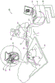
Fig. 1 is a schematic illustration of a catheter-based ablation system 20 according to an embodiment of the present invention. The system 20 includes a catheter 21, wherein a shaft 22 of the catheter is inserted through a sheath 23 into a heart 26 of a patient 28. The proximal end of catheter 21 is connected to console 24. In the embodiments described herein, catheter 21 may be used for any suitable therapeutic and/or diagnostic purpose, such as electrical sensing and/or ablation of tissue in heart 26.
The physician 30 inserts the shaft 22 through the vascular system of a patient 28 lying on a table 29. Catheter 21 includes a balloon assembly 40 fitted at the distal end of shaft 22. During insertion of shaft 22, balloon assembly 40 remains in the collapsed configuration. The physician 30 navigates the balloon assembly 40 to a target location in the heart 26 by manipulating the shaft 22 using the manipulator 32 near the proximal end of the catheter. Once the distal end of the shaft 22 has reached the target location, the physician 30 inflates the balloon assembly 40 and operates the console 24 to sense the signal and apply ablation energy to the tissue at the target location.
Variable phase generation and detection for RF ablation
Fig. 2 is a schematic diagram of a catheter-based ablation system 20 using a class D amplifier 54, according to an embodiment of the present invention. Physically, as shown, the catheter distal end 22 is provided with an RF ablation device comprising a plurality of electrodes 59, with the outputs of the amplifier 54 being coupled to the electrodes 59, respectively, by wires passing through the catheter which is coupled at its proximal end to the control-console 24 comprising the control unit 50.
In fig. 2, the catheter distal end is shown as a linear array of electrodes for clarity only. In practice, the distal end typically includes a multi-electrode geometry suitable for the ablation procedure in question. An exemplary configuration is an inflatable balloon or extendable basket assembly for performing pulmonary vein ablation.
In the present example, the control unit 50 controls in parallel the number of class D amplifiers equal to the number of electrodes 59. Each of the class D amplifiers includes a phase shifter 52 and an amplifier 54. The control unit 50 comprises a common signal generator 46 which generates a common RF signal 47 which is split into replicas 48 of the RF signal 47 for driving amplifiers 54. The control unit 50 commands each of the phase shifters 52 to assign a respective phase to the input current waveform of the amplifier 54, which is then amplified into an output current waveform 55 which is injected into the patient's body 49 through the associated electrode 59.
As can be seen, the resulting ablation current 66 flows locally through the ablated tissue 64 and then through the patient's body 49 and is collected by the common back patch electrode 62. However, the finite resistance of the tissue between any two electrodes (e.g., through blood in the case of an ablated vessel), as indicated by coupling resistance 58, may cause a portion of the injected current 55 to take a path from one electrode to the other in the form of a cross-talk current 57.
The control unit 50 includes an analyzer 60 that analyzes the return current 68 waveform and determines the actual current amplitude of each injected ablation current 66 based on its measured instantaneous amplitude and phase (possibly other inputs required for the calculation). Based on the requirements and computational steps implemented in a given optimization algorithm, the analyzer adjusts the amplitude and/or phase of one or more of the currents 55 to optimize the amplitude and phase of the currents 55 for meeting certain requirements, some of which are detailed below. The control unit 50 receives these optimized amplitudes and phases in real time and instructs the phase shifter 52 and/or the amplifier 54 in real time to responsively modify at least a portion of the phase and amplitude of the injected current waveform 55. In one possible implementation, a given optimization algorithm may utilize the instantaneous measured output voltage and current of amplifier 54 to adjust crosstalk current 57 in real time. For example, the algorithm may diagonalize the "current matrix" to set the crosstalk current 57 to zero. Additionally or alternatively, other optimization algorithms, such as those incorporating measured instantaneous amplitude and phase of the back patch electrode 62, may be applied with given constraints and/or cost functions.
Fig. 3 is a schematic diagram illustrating certain details of the operation of an ablation system, according to an embodiment of the invention. As shown, the waveform in inset 69 generally includes different values for amplitude 71 and phase 73. The voltage and current sensors 56 measure the output voltage and current of the amplifier, and the analyzer 60 measures the instantaneous amplitude and phase of the return current 68, and uses this information to extract, among other things, the actual electrode output voltage and current. Thus, the disclosed method isolates and measures various current amplitudes 55 and 66 for each and one of the electrodes 59 and derives the crosstalk current 57.
By applying similar or virtually identical voltages across some or all of electrodes 59 in real time during ablation, crosstalk currents 57 may be reduced or even eliminated. This is achieved by modulating the current of all electrodes at the same frequency ω and by selecting the respective amplitudes and phases of the current waveform 55 in real time, as shown in the inset 69. Thus, when the voltage difference between any two electrodes (i.e., across resistor 58) is always kept to a minimum, cross-talk current between any two electrodes is reduced and even completely eliminated in some cases.
As described above, to actually achieve minimization, or even elimination, of the varying crosstalk current, the return current 68 should be analyzed by the analyzer 60 at a sufficiently high rate to cause amplitude and phase selection to occur at a sufficiently high rate and short response time. Such a closed loop fit of the analytical modification of the current may be achieved, for example, in the hundreds of MHz frequency range by using suitable electronic circuits and non-linear amplifiers (such as phase shifters and class D amplifier operation).
Fig. 4 is a flow chart schematically illustrating a method for controlling ablation current, in accordance with an embodiment of the present invention. As shown, the crosstalk current value is controlled in a closed loop. Phase shifters 52 assign a phase to each of the replicas 48 of the RF signal 47, at a phase selection step 70. Amplifier 54 sets the amplitude of each of currents 55 at a current amplification step 72.
The back patch 62 collects the actual ablation current 66 and the analyzer 60 analyzes its amplitude in real time for analyzing the measured output voltage and current of the amplifier 54 provided by the sensor 56, at an electrode current actual amplitude extraction step 74. Knowing the current 55 in real time enables the analyzer 60 to extract real-time values of the crosstalk current 57. At decision step 76, the analyzer 60 compares the crosstalk current 57 value to a specified limit. If the crosstalk current is within predetermined limits, no action is taken and the various amplitude phases are maintained, as shown at a hold phase and amplitude step 78. At an amplitude and phase recalculation step 80, the analyzer 60 recalculates the amplitude and phase if one or more of the crosstalk currents exceed the limits. The method loops back to steps 70 and 72 and continues until the ablation process is complete.
The exemplary configuration shown in the figures was chosen solely for the sake of conceptual clarity. In alternative embodiments, the disclosed techniques may use any other suitable amplification scheme and amplifier type that performs the set of tasks described above, including amplification circuits other than, for example, class D amplifier-based amplification circuits.
The various system elements shown in fig. 1-3 may be implemented using suitable hardware or firmware. For example, the generator 46 may be implemented as a suitable high-speed Field Programmable Gate Array (FPGA) or Application Specific Integrated Circuit (ASIC). Some system elements, such as, for example, analyzer 60, may be implemented using software running on a programmable processor or using a combination of hardware and software elements.
The optimization objective may be related to either of the output current and the voltage. Further, the ablation device may have different geometries, such as an inflatable balloon, a spiral, multiple arms, and the like. The ablation device may include a temperature sensor in proximity to the electrode, wherein the system may control at least a portion of the ablation process using an algorithm that includes the electrode temperature.
Although the embodiments described herein are primarily directed to ablation applications, the methods and systems described herein may also be used in other medical applications.
It will thus be appreciated that the embodiments described above are cited by way of example, and that the present invention is not limited to what has been particularly shown and described hereinabove. Rather, the scope of the present invention includes both combinations and subcombinations of the various features described hereinabove, as well as variations and modifications thereof which would occur to persons skilled in the art upon reading the foregoing description and which are not disclosed in the prior art. Documents incorporated by reference into this patent application are considered an integral part of the application, except that definitions in this specification should only be considered if any term defined in these incorporated documents conflicts with a definition explicitly or implicitly set forth in this specification.
Claims (10)
Applications Claiming Priority (3)
| Application Number | Priority Date | Filing Date | Title |
|---|---|---|---|
| US15/697,811 US10945781B2 (en) | 2017-09-07 | 2017-09-07 | Variable phase generation and detection for radio-frequency (RF) ablation |
| US15/697811 | 2017-09-07 | ||
| PCT/IB2018/056696 WO2019049012A1 (en) | 2017-09-07 | 2018-09-02 | Variable phase generation and detection for radio-frequency (rf) ablation |
Publications (2)
| Publication Number | Publication Date |
|---|---|
| CN111050680A true CN111050680A (en) | 2020-04-21 |
| CN111050680B CN111050680B (en) | 2024-04-16 |
Family
ID=63720730
Family Applications (1)
| Application Number | Title | Priority Date | Filing Date |
|---|---|---|---|
| CN201880058029.1A Active CN111050680B (en) | 2017-09-07 | 2018-09-02 | Variable Phase Generation and Detection for Radiofrequency (RF) Ablation |
Country Status (6)
| Country | Link |
|---|---|
| US (1) | US10945781B2 (en) |
| EP (1) | EP3678569B1 (en) |
| JP (1) | JP7293202B2 (en) |
| CN (1) | CN111050680B (en) |
| IL (1) | IL272898B (en) |
| WO (1) | WO2019049012A1 (en) |
Families Citing this family (6)
| Publication number | Priority date | Publication date | Assignee | Title |
|---|---|---|---|---|
| US11826088B2 (en) | 2018-12-28 | 2023-11-28 | Biosense Webster (Israel) Ltd. | Adjusting phases of multiphase ablation generator to detect contact |
| US20210038280A1 (en) * | 2019-08-08 | 2021-02-11 | John Pikramenos | Electrosurgical generator for optimizing power output |
| US20210361340A1 (en) * | 2020-05-21 | 2021-11-25 | Covidien Lp | Independent control of dual rf electrosurgery |
| US20210361339A1 (en) * | 2020-05-21 | 2021-11-25 | Covidien Lp | Independent control of dual rf monopolar electrosurgery with shared return electrode |
| US11793565B2 (en) * | 2020-09-29 | 2023-10-24 | Biosense Webster (Israel) Ltd. | Detecting electrode contact using absolute and relative thresholds |
| US20220160421A1 (en) * | 2020-11-25 | 2022-05-26 | Biosense Webster (Israel) Ltd. | Single frequency switch mode power supply generator with phase shifter |
Citations (7)
| Publication number | Priority date | Publication date | Assignee | Title |
|---|---|---|---|---|
| US20030199862A1 (en) * | 2002-04-22 | 2003-10-23 | Simpson John A. | RF ablation apparatus and method using multi-frequency energy delivery |
| US20100030210A1 (en) * | 2008-08-01 | 2010-02-04 | Paulus Joseph A | Polyphase Electrosurgical System and Method |
| US20100117659A1 (en) * | 2008-11-12 | 2010-05-13 | Daniel Osadchy | Calibration and compensation for errors in position measurement |
| US20110190755A1 (en) * | 2010-01-29 | 2011-08-04 | Medtronic Ablation Frontiers Llc | Patient return electrode detection for ablation system |
| US20140058248A1 (en) * | 2011-04-21 | 2014-02-27 | Koninklijke Philips N.V. | Mr imaging guided therapy system |
| WO2014118734A2 (en) * | 2013-01-31 | 2014-08-07 | David Prutchi | Unipolar and/or bipolar ablation catheter |
| CN105615995A (en) * | 2014-11-24 | 2016-06-01 | 韦伯斯特生物官能(以色列)有限公司 | Irrigated ablation catheter with multiple sensors |
Family Cites Families (18)
| Publication number | Priority date | Publication date | Assignee | Title |
|---|---|---|---|---|
| US5383917A (en) | 1991-07-05 | 1995-01-24 | Jawahar M. Desai | Device and method for multi-phase radio-frequency ablation |
| US5837001A (en) | 1995-12-08 | 1998-11-17 | C. R. Bard | Radio frequency energy delivery system for multipolar electrode catheters |
| AU9687598A (en) | 1997-10-06 | 1999-04-27 | Somnus Medical Technologies, Inc. | Electro-surgical instrument with a graphical user interface |
| US6050994A (en) | 1998-05-05 | 2000-04-18 | Cardiac Pacemakers, Inc. | RF ablation apparatus and method using controllable duty cycle with alternate phasing |
| US6059778A (en) | 1998-05-05 | 2000-05-09 | Cardiac Pacemakers, Inc. | RF ablation apparatus and method using unipolar and bipolar techniques |
| US7252664B2 (en) | 2000-05-12 | 2007-08-07 | Cardima, Inc. | System and method for multi-channel RF energy delivery with coagulum reduction |
| JP2003533267A (en) | 2000-05-12 | 2003-11-11 | カーディマ・インコーポレイテッド | Multi-channel RF energy transmission system capable of reducing agglomerates |
| US6807446B2 (en) | 2002-09-03 | 2004-10-19 | Celsion Corporation | Monopole phased array thermotherapy applicator for deep tumor therapy |
| US20050107833A1 (en) | 2003-11-13 | 2005-05-19 | Freeman Gary A. | Multi-path transthoracic defibrillation and cardioversion |
| FR2864439B1 (en) * | 2003-12-30 | 2010-12-03 | Image Guided Therapy | DEVICE FOR TREATING A VOLUME OF BIOLOGICAL TISSUE BY LOCALIZED HYPERTHERMIA |
| EP2532321A1 (en) | 2006-01-17 | 2012-12-12 | Endymed Medical Ltd. | Electrosurgical methods and devices employing phase-controlled radiofrequency energy |
| KR100739002B1 (en) | 2006-04-28 | 2007-07-12 | (주) 태웅메디칼 | Multi RF Generator for High Frequency Thermal Therapy |
| US7896871B2 (en) * | 2007-02-22 | 2011-03-01 | Medtronic, Inc. | Impedance computation for ablation therapy |
| US20100130976A1 (en) * | 2008-11-21 | 2010-05-27 | Smith & Nephew Inc. | Reducing cross-talk effects in an rf electrosurgical device |
| US8610501B2 (en) | 2009-11-16 | 2013-12-17 | Covidien Lp | Class resonant-H electrosurgical generators |
| EP2765939B1 (en) | 2011-10-15 | 2018-09-26 | Diros Technology Inc. | Apparatus for precisely controlling the size and shape of radiofrequency ablations |
| US9277957B2 (en) | 2012-08-15 | 2016-03-08 | Ethicon Endo-Surgery, Inc. | Electrosurgical devices and methods |
| US20150272655A1 (en) | 2014-03-27 | 2015-10-01 | Medtronic Ablation Frontiers, Llc | Controlled rf energy in a multi-electrode catheter |
-
2017
- 2017-09-07 US US15/697,811 patent/US10945781B2/en active Active
-
2018
- 2018-09-02 EP EP18780225.1A patent/EP3678569B1/en active Active
- 2018-09-02 CN CN201880058029.1A patent/CN111050680B/en active Active
- 2018-09-02 JP JP2020513767A patent/JP7293202B2/en active Active
- 2018-09-02 WO PCT/IB2018/056696 patent/WO2019049012A1/en not_active Ceased
-
2020
- 2020-02-25 IL IL272898A patent/IL272898B/en unknown
Patent Citations (7)
| Publication number | Priority date | Publication date | Assignee | Title |
|---|---|---|---|---|
| US20030199862A1 (en) * | 2002-04-22 | 2003-10-23 | Simpson John A. | RF ablation apparatus and method using multi-frequency energy delivery |
| US20100030210A1 (en) * | 2008-08-01 | 2010-02-04 | Paulus Joseph A | Polyphase Electrosurgical System and Method |
| US20100117659A1 (en) * | 2008-11-12 | 2010-05-13 | Daniel Osadchy | Calibration and compensation for errors in position measurement |
| US20110190755A1 (en) * | 2010-01-29 | 2011-08-04 | Medtronic Ablation Frontiers Llc | Patient return electrode detection for ablation system |
| US20140058248A1 (en) * | 2011-04-21 | 2014-02-27 | Koninklijke Philips N.V. | Mr imaging guided therapy system |
| WO2014118734A2 (en) * | 2013-01-31 | 2014-08-07 | David Prutchi | Unipolar and/or bipolar ablation catheter |
| CN105615995A (en) * | 2014-11-24 | 2016-06-01 | 韦伯斯特生物官能(以色列)有限公司 | Irrigated ablation catheter with multiple sensors |
Also Published As
| Publication number | Publication date |
|---|---|
| WO2019049012A1 (en) | 2019-03-14 |
| IL272898A (en) | 2020-04-30 |
| EP3678569B1 (en) | 2025-12-24 |
| JP2020533073A (en) | 2020-11-19 |
| EP3678569A1 (en) | 2020-07-15 |
| US20190069943A1 (en) | 2019-03-07 |
| US10945781B2 (en) | 2021-03-16 |
| CN111050680B (en) | 2024-04-16 |
| JP7293202B2 (en) | 2023-06-19 |
| IL272898B (en) | 2022-02-01 |
Similar Documents
| Publication | Publication Date | Title |
|---|---|---|
| CN111050680B (en) | Variable Phase Generation and Detection for Radiofrequency (RF) Ablation | |
| US12440261B2 (en) | Adjusting phases of multiphase ablation generator to detect contact | |
| JP7114282B2 (en) | Simultaneous control of power and perfusion during ablation | |
| US10893904B2 (en) | Temperature controlled short duration ablation | |
| EP3202355B1 (en) | Temperature controlled short duration ablation | |
| US10973574B2 (en) | Temperature controlled short duration ablation | |
| US10507058B2 (en) | Temperature controlled short duration ablation | |
| EP3513839B1 (en) | Power controlled short duration ablation with varying temperature limits | |
| JP7646979B2 (en) | Careful irreversible electroporation (IRE) protocol to avoid air bubble generation | |
| EP3769710B1 (en) | Myocardial tissue ablation with narrow temperature variation | |
| JP7760362B2 (en) | Control of interelectrode current during ablation | |
| JP2021065706A (en) | Ablation of lesions of low to medium depths using ultrahigh radiofrequency (rf) power for ultrashort duration |
Legal Events
| Date | Code | Title | Description |
|---|---|---|---|
| PB01 | Publication | ||
| PB01 | Publication | ||
| SE01 | Entry into force of request for substantive examination | ||
| SE01 | Entry into force of request for substantive examination | ||
| GR01 | Patent grant | ||
| GR01 | Patent grant |