CN111034225B - Audio signal processing method and apparatus using stereo reverberation signal - Google Patents
Audio signal processing method and apparatus using stereo reverberation signal Download PDFInfo
- Publication number
- CN111034225B CN111034225B CN201880052564.6A CN201880052564A CN111034225B CN 111034225 B CN111034225 B CN 111034225B CN 201880052564 A CN201880052564 A CN 201880052564A CN 111034225 B CN111034225 B CN 111034225B
- Authority
- CN
- China
- Prior art keywords
- signal
- audio signal
- channel
- ambisonic
- processing apparatus
- Prior art date
- Legal status (The legal status is an assumption and is not a legal conclusion. Google has not performed a legal analysis and makes no representation as to the accuracy of the status listed.)
- Active
Links
Images


Classifications
-
- H—ELECTRICITY
- H04—ELECTRIC COMMUNICATION TECHNIQUE
- H04S—STEREOPHONIC SYSTEMS
- H04S7/00—Indicating arrangements; Control arrangements, e.g. balance control
- H04S7/30—Control circuits for electronic adaptation of the sound field
- H04S7/302—Electronic adaptation of stereophonic sound system to listener position or orientation
- H04S7/303—Tracking of listener position or orientation
- H04S7/304—For headphones
-
- G—PHYSICS
- G10—MUSICAL INSTRUMENTS; ACOUSTICS
- G10L—SPEECH ANALYSIS TECHNIQUES OR SPEECH SYNTHESIS; SPEECH RECOGNITION; SPEECH OR VOICE PROCESSING TECHNIQUES; SPEECH OR AUDIO CODING OR DECODING
- G10L19/00—Speech or audio signals analysis-synthesis techniques for redundancy reduction, e.g. in vocoders; Coding or decoding of speech or audio signals, using source filter models or psychoacoustic analysis
- G10L19/02—Speech or audio signals analysis-synthesis techniques for redundancy reduction, e.g. in vocoders; Coding or decoding of speech or audio signals, using source filter models or psychoacoustic analysis using spectral analysis, e.g. transform vocoders or subband vocoders
- G10L19/0204—Speech or audio signals analysis-synthesis techniques for redundancy reduction, e.g. in vocoders; Coding or decoding of speech or audio signals, using source filter models or psychoacoustic analysis using spectral analysis, e.g. transform vocoders or subband vocoders using subband decomposition
-
- G—PHYSICS
- G10—MUSICAL INSTRUMENTS; ACOUSTICS
- G10L—SPEECH ANALYSIS TECHNIQUES OR SPEECH SYNTHESIS; SPEECH RECOGNITION; SPEECH OR VOICE PROCESSING TECHNIQUES; SPEECH OR AUDIO CODING OR DECODING
- G10L21/00—Speech or voice signal processing techniques to produce another audible or non-audible signal, e.g. visual or tactile, in order to modify its quality or its intelligibility
- G10L21/02—Speech enhancement, e.g. noise reduction or echo cancellation
- G10L21/038—Speech enhancement, e.g. noise reduction or echo cancellation using band spreading techniques
-
- H—ELECTRICITY
- H04—ELECTRIC COMMUNICATION TECHNIQUE
- H04S—STEREOPHONIC SYSTEMS
- H04S1/00—Two-channel systems
- H04S1/002—Non-adaptive circuits, e.g. manually adjustable or static, for enhancing the sound image or the spatial distribution
-
- H—ELECTRICITY
- H04—ELECTRIC COMMUNICATION TECHNIQUE
- H04S—STEREOPHONIC SYSTEMS
- H04S3/00—Systems employing more than two channels, e.g. quadraphonic
- H04S3/02—Systems employing more than two channels, e.g. quadraphonic of the matrix type, i.e. in which input signals are combined algebraically, e.g. after having been phase shifted with respect to each other
-
- G—PHYSICS
- G10—MUSICAL INSTRUMENTS; ACOUSTICS
- G10L—SPEECH ANALYSIS TECHNIQUES OR SPEECH SYNTHESIS; SPEECH RECOGNITION; SPEECH OR VOICE PROCESSING TECHNIQUES; SPEECH OR AUDIO CODING OR DECODING
- G10L19/00—Speech or audio signals analysis-synthesis techniques for redundancy reduction, e.g. in vocoders; Coding or decoding of speech or audio signals, using source filter models or psychoacoustic analysis
- G10L19/008—Multichannel audio signal coding or decoding using interchannel correlation to reduce redundancy, e.g. joint-stereo, intensity-coding or matrixing
-
- G—PHYSICS
- G10—MUSICAL INSTRUMENTS; ACOUSTICS
- G10L—SPEECH ANALYSIS TECHNIQUES OR SPEECH SYNTHESIS; SPEECH RECOGNITION; SPEECH OR VOICE PROCESSING TECHNIQUES; SPEECH OR AUDIO CODING OR DECODING
- G10L19/00—Speech or audio signals analysis-synthesis techniques for redundancy reduction, e.g. in vocoders; Coding or decoding of speech or audio signals, using source filter models or psychoacoustic analysis
- G10L19/04—Speech or audio signals analysis-synthesis techniques for redundancy reduction, e.g. in vocoders; Coding or decoding of speech or audio signals, using source filter models or psychoacoustic analysis using predictive techniques
- G10L19/16—Vocoder architecture
- G10L19/173—Transcoding, i.e. converting between two coded representations avoiding cascaded coding-decoding
-
- H—ELECTRICITY
- H04—ELECTRIC COMMUNICATION TECHNIQUE
- H04R—LOUDSPEAKERS, MICROPHONES, GRAMOPHONE PICK-UPS OR LIKE ACOUSTIC ELECTROMECHANICAL TRANSDUCERS; DEAF-AID SETS; PUBLIC ADDRESS SYSTEMS
- H04R2499/00—Aspects covered by H04R or H04S not otherwise provided for in their subgroups
- H04R2499/10—General applications
- H04R2499/15—Transducers incorporated in visual displaying devices, e.g. televisions, computer displays, laptops
-
- H—ELECTRICITY
- H04—ELECTRIC COMMUNICATION TECHNIQUE
- H04R—LOUDSPEAKERS, MICROPHONES, GRAMOPHONE PICK-UPS OR LIKE ACOUSTIC ELECTROMECHANICAL TRANSDUCERS; DEAF-AID SETS; PUBLIC ADDRESS SYSTEMS
- H04R5/00—Stereophonic arrangements
- H04R5/04—Circuit arrangements, e.g. for selective connection of amplifier inputs/outputs to loudspeakers, for loudspeaker detection, or for adaptation of settings to personal preferences or hearing impairments
-
- H—ELECTRICITY
- H04—ELECTRIC COMMUNICATION TECHNIQUE
- H04S—STEREOPHONIC SYSTEMS
- H04S2420/00—Techniques used stereophonic systems covered by H04S but not provided for in its groups
- H04S2420/01—Enhancing the perception of the sound image or of the spatial distribution using head related transfer functions [HRTF's] or equivalents thereof, e.g. interaural time difference [ITD] or interaural level difference [ILD]
-
- H—ELECTRICITY
- H04—ELECTRIC COMMUNICATION TECHNIQUE
- H04S—STEREOPHONIC SYSTEMS
- H04S2420/00—Techniques used stereophonic systems covered by H04S but not provided for in its groups
- H04S2420/03—Application of parametric coding in stereophonic audio systems
-
- H—ELECTRICITY
- H04—ELECTRIC COMMUNICATION TECHNIQUE
- H04S—STEREOPHONIC SYSTEMS
- H04S2420/00—Techniques used stereophonic systems covered by H04S but not provided for in its groups
- H04S2420/11—Application of ambisonics in stereophonic audio systems
Landscapes
- Engineering & Computer Science (AREA)
- Physics & Mathematics (AREA)
- Acoustics & Sound (AREA)
- Signal Processing (AREA)
- Computational Linguistics (AREA)
- Multimedia (AREA)
- Human Computer Interaction (AREA)
- Audiology, Speech & Language Pathology (AREA)
- Health & Medical Sciences (AREA)
- Mathematical Physics (AREA)
- Quality & Reliability (AREA)
- Spectroscopy & Molecular Physics (AREA)
- Theoretical Computer Science (AREA)
- Pure & Applied Mathematics (AREA)
- Mathematical Optimization (AREA)
- Mathematical Analysis (AREA)
- General Physics & Mathematics (AREA)
- Algebra (AREA)
- Stereophonic System (AREA)
Abstract
公开一种用于渲染输入音频信号的音频信号处理装置。音频信号处理装置可以包括处理器,该处理器被配置成获得包括立体混响信号和非剧情声道差分信号的输入音频信号,渲染立体混响信号以生成第一输出音频信号,将第一输出音频信号与非剧情声道差分信号混合以生成第二输出音频信号,并且输出第二输出音频信号。

An audio signal processing apparatus for rendering an input audio signal is disclosed. The audio signal processing apparatus may include a processor configured to obtain an input audio signal including a stereo reverberation signal and a non-dramatic channel differential signal, render the stereo reverberation signal to generate a first output audio signal, and convert the first output audio signal to the first output audio signal. The audio signal is mixed with the non-dramatic channel differential signal to generate a second output audio signal, and the second output audio signal is output.
Description
Technical Field
The present disclosure relates to an audio signal processing method and apparatus, and more particularly, to an audio signal processing method and apparatus for providing immersive sound for a portable device including a Head Mounted Display (HMD) device.
Background
To provide immersive and interactive audio in a Head Mounted Display (HMD) device, binaural rendering techniques are essentially required. Techniques for reproducing spatial sound corresponding to Virtual Reality (VR) are important factors that increase the realism of virtual reality and allow a VR device user to feel fully immersed therein. Audio signals rendered to reproduce spatial sound in virtual reality may be divided into scenario audio signals and non-scenario audio signals. Here, the storyline audio signal may be an audio signal interactively presented using information of a head direction and a user position. In addition, the non-storyline audio signal may be an audio signal in which the directivity is not important or the sound effect according to the sound quality is more important than the localization of the sound.
Meanwhile, in a mobile device limited by the amount of computation and power consumption, a burden of the amount of computation and power consumption may occur due to an increase in an object or a channel subject to rendering. In addition, the number of encoded streams in decodable audio formats supported by most user devices and playback software currently offered in the multimedia services market may be limited. In this case, the user device may receive the non-scenario audio signal separated from the non-scenario audio signal and provide it to the user. Alternatively, the user device may provide a multimedia service in which the non-storyline audio signal is omitted from the user. Accordingly, there is a need for a technique for improving efficiency of processing a scenario audio signal and a non-scenario audio signal.
Disclosure of Invention
Technical problem
Embodiments of the present disclosure efficiently transmit audio signals having various characteristics required to reproduce real spatial sound. In addition, the embodiments of the present disclosure will transmit an audio signal including a non-storyline audio signal as an audio signal for reproducing a storyline effect and a non-storyline effect through an audio format limited in the number of encoding streams included.
Technical solution
The audio signal processing apparatus for generating an output audio signal according to an embodiment of the present disclosure may include a processor configured to obtain an input audio signal including a first ambisonic signal and a non-dramatic channel signal, generate a second ambisonic signal including only a signal corresponding to a predetermined signal component among a plurality of signal components included in a ambisonic format of the first ambisonic signal based on the non-dramatic channel signal, and generate an output audio signal including a third ambisonic signal obtained by synthesizing the second ambisonic signal and the first ambisonic signal for each signal component. In this case, the non-scenario channel signal may represent an audio signal forming an audio scene that is fixed with respect to the listener.
Further, the predetermined signal component may be a signal component representing sound pressure of a sound field at a point where the ambisonic signal has been collected.
The processor may be configured to filter the non-storyline channel signal with a first filter to generate a second ambisonic signal. In this case, the first filter may be an inverse filter of a second filter for binaural rendering of the third ambisonic signal as an output audio signal in an output device that has received the third ambisonic signal.
The processor may be configured to obtain information on a plurality of virtual channels arranged in a virtual space in which the output audio signal is simulated, and generate the first filter based on the information of the plurality of virtual channels. In this case, the information of the plurality of virtual channels may be a plurality of virtual channels for rendering the third ambisonic signal.
The information of the plurality of virtual channels may include position information representing a position of each of the plurality of virtual channels. In this case, the processor may be configured to obtain a plurality of binaural filters corresponding to the position of each of the plurality of virtual channels based on the position information, and generate the first filter based on the plurality of binaural filters.
The processor may be configured to generate the first filter based on a sum of filter coefficients included in the plurality of binaural filters.
The processor may be configured to generate the first filter based on an inverse operation result of a sum of the filter coefficients and a number of the plurality of virtual channels.
The second filter may include a plurality of binaural filters for each signal component respectively corresponding to each signal component included in the ambisonic signal. Also, the first filter may be an inverse filter of a binaural filter corresponding to a predetermined signal component among a plurality of binaural filters for each signal component. The frequency response of the first filter may be a response having a constant magnitude in the frequency domain.
The non-scenario channel signal may be a 2-channel signal composed of a first channel signal and a second channel signal. In this case, the processor may be configured to generate a difference signal between the first channel signal and the second channel signal, and generate an output audio signal including the difference signal and the third ambisonic signal.
The processor may be configured to generate a second ambisonic signal based on a signal obtained by synthesizing the first channel signal and the second channel signal in a time domain.
The first channel signal and the second channel signal may be channel signals corresponding to different regions with respect to a plane dividing a virtual space in which the second output audio signal is simulated into two regions.
The processor may be configured to encode the output audio signal to generate a bitstream, and transmit the generated bitstream to an output device. In addition, the output device may be an apparatus for rendering an audio signal generated by decoding a bitstream. When the number of encoded streams used to generate the bit stream is N, the output audio signal may include a third ambisonic signal composed of N-1 signal components corresponding to the N-1 encoded streams and a differential signal corresponding to one encoded stream.
Specifically, the maximum number of coded streams supported by the codec for generating the bitstream may be five.
A method for operating an audio signal processing apparatus for generating an output audio signal according to another embodiment of the present disclosure may include obtaining an input audio signal including a first ambisonic signal and a non-storic channel difference signal; generating a second ambisonic signal including only a signal corresponding to a predetermined signal component among a plurality of signal components included in a ambisonic format of the first ambisonic signal based on the non-dramatic channel signal; and generating an output audio signal comprising a third ambisonic signal obtained by synthesizing the second and first ambisonic signals for each signal component. In this case, the non-scenario channel signal may represent an audio signal forming an audio scene that is fixed with respect to the listener. In addition, the predetermined signal component may be a signal component representing sound pressure of a sound field at a point where the ambisonic signal has been collected.
According to another embodiment of the present invention, an audio signal processing apparatus for rendering an input audio signal may include a processor configured to obtain an input audio signal including a ambisonic signal and a non-scenario channel differential signal, render the ambisonic signal to generate a first output audio signal, mix the first output audio signal and the non-scenario channel differential signal to generate a second output audio signal, and output the second output audio signal. In this case, the non-scenario channel difference signal may be a difference signal representing a difference between a first channel signal and a second channel signal constituting the 2-channel audio signal. In addition, each of the first channel signal and the second channel signal may be an audio signal forming an audio scene that is fixed with respect to a listener.
The ambisonic signal may include a non-storic ambisonic signal generated based on a signal obtained by synthesizing the first channel signal and the second channel signal. In this case, the non-storyline ambisonic signal may include only a signal corresponding to a predetermined signal component among a plurality of signal components included in the ambisonic format of the ambisonic signal. In addition, the predetermined signal component may be a signal component representing sound pressure of a sound field at a point where the ambisonic signal has been collected.
Specifically, the non-storyline ambisonic signal may be a signal obtained by filtering, with a first filter, a signal that has been obtained by synthesizing the first channel signal and the second channel signal in the time domain. In this case, the first filter may be an inverse filter of a second filter for binaural rendering of the ambisonic signal as the first output audio signal.
The first filter may be generated based on information on a plurality of virtual channels arranged in a virtual space in which the first output audio signal is simulated.
The information of the plurality of virtual channels may include position information representing a position of each of the plurality of virtual channels. In this case, the first filter may be generated based on a plurality of binaural filters corresponding to a position of each of the plurality of virtual channels. In addition, a plurality of binaural filters may be determined based on the location information.
The first filter may be generated based on a sum of filter coefficients included in the plurality of binaural filters.
The first filter may be generated based on a result of an inverse operation of a sum of the filter coefficients and the number of the plurality of virtual channels.
The second filter may include a plurality of binaural filters for each signal component respectively corresponding to each signal component included in the ambisonic signal. Also, the first filter may be an inverse filter of a binaural filter corresponding to a predetermined signal component of the plurality of binaural filters for each signal component. In this case, the frequency response of the first filter may have a constant magnitude in the frequency domain.
The processor may be configured to binaural render the ambisonic signal based on information of a plurality of virtual channels arranged in a virtual space to generate a first output audio signal and mix the first output audio signal with the non-storyline channel difference signal to generate a second output audio signal.
The second output audio signal may include a plurality of output audio signals respectively corresponding to each of the plurality of channels according to a predetermined channel layout. In this case, the processor may be configured to generate a first output audio signal including a plurality of output channel signals respectively corresponding to each of the plurality of channels by performing channel rendering on the ambisonic signal based on position information indicating a position respectively corresponding to each of the plurality of channels, and may generate a second output audio signal by mixing the first output audio signal and the non-storic channel difference signal based on the position information for each channel. Each of the plurality of output channel signals may include an audio signal obtained by synthesizing a first channel signal and a second channel signal.
The middle plane may represent a plane perpendicular to the horizontal plane of the predetermined channel layout and having the same center as the horizontal plane. In this case, the processor may be configured to generate the second output audio signal by mixing the non-storyline channel difference signal with the first output audio signal differently for each of a channel corresponding to the left side with respect to the middle plane, a channel corresponding to the right side with respect to the middle plane, and a channel corresponding to the middle plane among the plurality of channels.
The processor may be configured to decode the bitstream to obtain an input audio signal. In this case, the maximum number of streams supported by a codec for generating a bitstream is N, and the bitstream may be generated based on a ambisonic signal composed of N-1 signal components corresponding to N-1 streams and a non-storyline channel difference signal corresponding to one stream. In addition, the maximum number of streams supported by the codec of the bitstream may be five.
The first channel signal and the second channel signal may be channel signals corresponding to different regions with respect to a plane dividing a virtual space in which the second output audio signal is simulated into two regions. In addition, the first output audio signal may include a signal obtained by synthesizing the first channel signal and the second channel signal.
A method for operating an audio signal processing apparatus for rendering an input audio signal according to another aspect of the present disclosure may include: obtaining an input audio signal comprising a ambisonic signal and a non-storic channel difference signal; rendering the ambisonic signal to generate a first output audio signal; mixing the first output audio signal with the non-storyline channel differential signal to generate a second output audio signal; and outputting the second output audio signal. In this case, the non-scenario channel difference signal may be a difference signal representing a difference between a first channel signal and a second channel signal constituting the 2-channel audio signal, and the first channel signal and the second channel signal may be audio signals forming an audio scene fixed with respect to a listener.
An electronic device readable recording medium according to another aspect may include a recording medium in which a program for executing the above-described method in an electronic device is recorded.
Advantageous effects
An audio signal processing apparatus according to an embodiment of the present disclosure may provide an immersive three-dimensional audio signal. In addition, the audio signal processing apparatus according to the embodiment of the present disclosure may improve efficiency of processing a non-scenario audio signal. In addition, the audio signal processing apparatus according to the embodiment of the present disclosure can efficiently transmit audio signals necessary for reproducing spatial sound through various codecs.
Drawings
Fig. 1 is a schematic diagram illustrating a system including an audio signal processing apparatus and a rendering apparatus according to an embodiment of the present disclosure;
fig. 2 is a flowchart illustrating an operation of an audio signal processing apparatus according to an embodiment of the present disclosure;
fig. 3 is a flowchart illustrating a method for processing a non-storyline channel signal by an audio signal processing apparatus according to an embodiment of the present disclosure;
fig. 4 is a schematic diagram illustrating in detail non-storyline channel signal processing by an audio signal processing apparatus according to an embodiment of the present disclosure;
fig. 5 is a schematic diagram illustrating a method of generating an output audio signal including a non-storyline channel signal based on an input audio signal including a non-storyline ambisonic signal by a rendering apparatus according to an embodiment of the present disclosure;
fig. 6 is a schematic diagram illustrating a method of generating an output audio signal by a rendering apparatus by channel-rendering an input audio signal including a non-storyline ambisonic signal according to an embodiment of the present disclosure;
fig. 7 is a schematic diagram illustrating an operation of an audio signal processing apparatus when the audio signal processing apparatus supports a codec for encoding a 5.1-channel signal according to an embodiment of the present disclosure; and
fig. 8 and 9 are block diagrams illustrating configurations of an audio signal processing apparatus and a rendering apparatus according to an embodiment of the present disclosure.
Detailed Description
Hereinafter, embodiments of the present invention will be described in detail with reference to the accompanying drawings so that those skilled in the art can easily practice the invention. This invention may, however, be embodied in many different forms and should not be construed as limited to the embodiments set forth herein. Some parts of the embodiments that are not relevant to the description are not illustrated in the drawings to clearly describe the embodiments of the present disclosure, and like reference numerals refer to like elements throughout the specification.
In addition, when a portion is referred to as "comprising" or "includes" any component, it means that the portion may further include other components, not excluding other components, unless otherwise specified.
The present disclosure relates to an audio signal processing method for processing an audio signal including a non-storyline audio signal. The non-storyline audio signal may be a signal forming an audio scene that is fixed relative to the listener. In the virtual space, the directivity of the sound output corresponding to the non-scenario audio signal may not change regardless of the motion of the listener. According to the audio signal processing method of the present disclosure, it is possible to reduce the number of encoded streams for a non-storyline effect while maintaining the sound quality of a non-storyline audio signal included in an input audio signal. An audio signal processing apparatus according to an embodiment of the present disclosure may filter a non-scenario channel signal to generate a signal that may be synthesized with a scenario ambisonic signal. Also, the audio signal processing apparatus 100 may encode output audio signals including a scenario audio signal and a non-scenario audio signal. Through the above, the audio signal processing apparatus 100 can efficiently transmit audio data corresponding to the scenario audio signal and the non-scenario audio signal to another apparatus.
Hereinafter, the present invention will be described in detail with reference to the accompanying drawings.
Fig. 1 is a schematic diagram illustrating a system including an audio signal processing apparatus 100 and a rendering apparatus 200 according to an embodiment of the present disclosure.
According to an embodiment of the present disclosure, the audio signal processing apparatus 100 may generate a first output audio signal 11 based on a first input audio signal 10. Further, the audio signal processing apparatus 100 may transmit the first output audio signal to the rendering apparatus 200. For example, the audio signal processing apparatus 100 may encode the first output audio signal 11 and transmit the encoded audio data.
According to an embodiment, the first input audio signal 10 may include a ambisonic signal B1 and a non-storyline channel signal. The audio signal processing apparatus 100 may generate the non-storyline ambisonic B2 based on the non-storyline channel signal. The audio signal processing apparatus 100 may synthesize the ambisonic signal B1 and the non-storic ambisonic signal B2 to generate an output ambisonic signal B3. The first output audio signal 11 may comprise the output ambisonic signal B3. In addition, when the non-scenario channel signal is a 2-channel signal, the audio signal processing apparatus 100 may generate a difference signal v between channels constituting the non-scenario channel. In this case, the first output audio signal 11 may include the output ambisonic signal B3 and the differential signal v. Through the above, the audio signal processing apparatus 100 may reduce the number of channels for the channel signal of the non-storyline effect included in the first output audio signal 11, as compared to the number of channels of the non-storyline channel signal included in the first input audio signal 10. A detailed method of processing a non-scenario channel signal by the audio signal processing apparatus 100 will be described with reference to fig. 2 to 4.
Furthermore, according to an embodiment, the audio signal processing apparatus 100 may encode the first output audio signal 11 to generate an encoded audio signal. For example, the audio signal processing apparatus 100 may map each of a plurality of signal components included in the output ambisonic signal B3 to a plurality of encoded streams. Also, the audio signal processing apparatus 100 may map the differential signal v to one encoded stream. The audio signal processing device 100 may encode the first output audio signal 11 based on the signal components assigned to the encoded stream. With the above, even when the number of encoded streams is limited according to the codec, the audio signal processing apparatus 100 can encode the non-scenario audio signal together with the scenario audio signal. In this regard, a detailed description will be given with reference to fig. 7. Through the above, the audio signal processing apparatus 100 according to an embodiment of the present disclosure may transmit encoded audio data to provide a user with sound including a non-storyline effect.
According to an embodiment of the present disclosure, the rendering apparatus 200 may obtain the second input audio signal 20. Specifically, the rendering apparatus 200 may receive encoded audio data from the audio signal processing apparatus 100. In addition, the rendering apparatus 200 may decode the encoded audio data to obtain the second input audio signal 20. In this case, the second input audio signal 20 may be different from the first output audio signal 11 depending on the encoding method. In particular, in case of audio data encoded by a lossless compression method, the second input audio signal 20 may be identical to the first output audio signal 11. The second input audio signal 20 may include a ambisonic signal B3'. Also, the second input audio signal 20 may also include a differential signal v'.
In addition, the rendering apparatus 200 may render the second input audio signal 20 to generate the second output audio signal 21. For example, the rendering apparatus 200 may perform binaural rendering on some signal components in the second input audio signal to generate the second output audio signal. Alternatively, the rendering apparatus 200 may perform channel rendering on some signal components in the second input audio signal to generate the second output audio signal. A method for generating the second output audio signal 21 by the rendering apparatus 200 will be described later with reference to fig. 5 and 6.
Meanwhile, in the present disclosure, the rendering apparatus 200 is described as an apparatus separate from the audio signal processing apparatus 100, but the present disclosure is not limited thereto. For example, at least some operations of the rendering apparatus 200 described in the present disclosure may also be performed in the audio signal processing apparatus 100. In addition, in fig. 1, encoding and decoding operations performed in the encoder of the audio signal processing apparatus 100 and the decoder of the rendering apparatus 200 may be omitted.
Fig. 2 is a flowchart illustrating an operation of the audio signal processing apparatus 100 according to an embodiment of the present disclosure. In step S202, the audio signal processing apparatus 100 may obtain an input audio signal. For example, the audio signal processing device 100 may receive input audio signals collected by one or more sound collection devices. The input audio signal may include at least one of a ambisonic signal, an object signal, and a speaker channel signal. Here, the ambisonic signal may be a signal recorded by a microphone array including a plurality of microphones. In addition, the ambisonic signal may be represented in an ambisonic format. The ambisonic format may be represented by converting the 360-degree spatial signals recorded by the microphone array to coefficients based on spherical harmonics. In particular, the ambisonic format may be referred to as a B-format.
Further, the input audio signal may include at least one of a scenario audio signal and a non-scenario audio signal. Here, the scenario audio signal may be an audio signal in which the position of a sound source corresponding to the audio signal changes according to the movement of a listener in a virtual space in which the audio signal is simulated. For example, the storyline audio signal may be represented by at least one of the aforementioned ambisonic signal, object signal, or speaker channel signal. In addition, as described above, the non-storyline audio signal may be an audio signal forming an audio scene that is fixed relative to the listener. Also, the non-storyline audio signal may be represented by a speaker channel signal. For example, when the non-scenario audio signal is a 2-channel audio signal, the positions of the sound sources corresponding to each channel signal constituting the non-scenario audio signal may be fixed to the positions of both ears of the listener. However, the present disclosure is not limited thereto. In the present disclosure, for convenience of description, the speaker channel signals may be referred to as channel signals. In addition, in the present disclosure, the non-scenario channel signal may mean a channel signal representing the above-described non-scenario characteristic among channel signals.
In step S204, the audio signal processing apparatus 100 may generate an output audio signal based on the input audio signal obtained by step S202. According to an embodiment, the input audio signal may include a ambisonic signal composed of at least one channel and a non-scenario channel audio signal. In this case, the ambisonic signal may be a storyline ambisonic signal. In this case, the audio signal processing apparatus 100 may generate the non-storyline ambisonic signal in a ambisonic format based on the non-storyline channel audio signal. In addition, the audio signal processing apparatus 100 may synthesize the non-storyline ambisonic signal and the ambisonic signal to generate an output audio signal.
The number N of signal components included in the above-described ambisonic signal may be determined based on the highest order of the ambisonic signal. The mth order ambisonic signal, in which the mth order is the highest order, may include (m +1)2A signal component. In this case, m may be an integer equal to or greater than 0. For example, when the order of the ambisonic signal included in the output audio signal is 3, the output audio signal may include 16 ambisonic signal components. In addition, the spherical harmonic function may vary according to the order m of the ambisonic format. The primary ambisonic signal may be referred to as first-order ambisonic (FoA). Also, the ambisonic signal having an order of 2 or more may be referred to as higher order ambisonic (HoA). In the present disclosure, the ambisonic signal may represent either the FoA signal or the HoA signal.
Further, according to the embodiment, the audio signal processing apparatus 100 may output an output audio signal. For example, the audio signal processing apparatus 100 may simulate sounds including a scenario sound and a non-scenario sound by outputting an audio signal. The audio signal processing apparatus 100 may transmit the output audio signal to an external device connected to the audio signal processing apparatus 100. For example, the external device connected to the audio signal processing apparatus 100 may be the rendering apparatus 200. The audio signal processing apparatus 100 may be connected to an external device through a wired/wireless interface.
According to an embodiment, the audio signal processing apparatus 100 may output encoded audio data. In the present disclosure, the output of the audio signal may include an operation of transmitting the digitized data. Specifically, the audio signal processing apparatus 100 may encode the output audio signal to generate audio data. In this case, the encoded audio data may be a bitstream. The audio signal processing device 100 may encode the first output audio signal based on the signal components assigned to the encoded stream. For example, the audio signal processing apparatus 100 may generate a Pulse Code Modulation (PCM) signal for each encoded stream. In addition, the audio signal processing apparatus 100 may transmit a plurality of generated PCM signals to the rendering apparatus 200.
According to an embodiment, the audio signal processing apparatus 100 may encode the output audio signal using a codec with a limited maximum number of encodable encoding streams. For example, the number of maximum encoded streams may be limited to 5. In this case, the audio signal processing apparatus 100 may generate an output audio signal composed of 5 signal components based on the input audio signal. For example, the output audio signal may be composed of 4 ambisonic signal components and one differential signal component included in the FoA signal. Next, the audio signal processing apparatus 100 may encode an output audio signal composed of 5 signal components to generate encoded audio data. In addition, the audio signal processing apparatus 100 may transmit encoded audio data. Meanwhile, the audio signal processing apparatus 100 may compress the encoded audio data by a lossless compression method or a lossy compression method. For example, the encoding process may include a process of compressing audio data.
Fig. 3 is a flowchart illustrating a method for processing a non-storyline channel signal by the audio signal processing apparatus 100 according to an embodiment of the present disclosure.
In step S302, the audio signal processing apparatus 100 may obtain an input audio signal including a non-storyline audio signal and a first ambisonic signal. According to an embodiment, the audio signal processing apparatus 100 may receive a plurality of ambisonic signals having different highest orders. In this case, the audio signal processing apparatus 100 may synthesize a plurality of ambisonic signals into one first ambisonic signal. For example, the audio signal processing apparatus 100 may generate the first ambisonic signal in a format of the maximum highest-order ambisonic among the plurality of ambisonic signals. Alternatively, the audio signal processing apparatus 100 may convert the HoA signal into an FoA signal to generate the first ambisonic signal in a dominant ambisonic format.
In step S304, the audio signal processing apparatus 100 may generate a second ambisonic signal based on the non-scenario channel signal obtained in step S302. For example, the audio signal processing apparatus 100 may generate the second ambisonic signal by filtering the non-storic ambisonic signal with the first filter. The first filter will be described in detail with reference to fig. 4.
According to an embodiment, the audio signal processing apparatus 100 may generate the second ambisonic signal including only a signal corresponding to a predetermined signal component among a plurality of signal components included in the first ambisonic signal of the ambisonic format. Here, the predetermined signal component may be a signal component representing sound pressure of a sound field at a point where the ambisonic signal has been collected. In this case, the predetermined signal component may not exhibit directivity toward a specific direction in a virtual space simulating the ambisonic signal. In addition, the second ambisonic signal may be a signal having a signal value of "0" corresponding to a signal component other than the predetermined signal component. This is because the non-storyline audio signals are audio signals that form an audio scene that is fixed relative to the listener. In addition, the pitch of the non-storyline audio signal can be maintained regardless of the head movements of the listener.
For example, the FoA signal B may be represented by [ equation 1 ]. FoA signal B contains W, X, Y and Z which may represent signals corresponding to each of the four signal components contained in FoA, respectively.
[ equation 1]
B=[W,X,Y,Z]T
In this case, the second ambisonic signal may representIs [ W2, 0, 0, 0] containing only W component]And T. In [ equation 1]]In (b), [ x ]]TRepresentation matrix [ x ]]The transposed matrix of (2). The predetermined signal component may be a first signal component w corresponding to a 0 th order ambisonic format. In this case, the first signal component w may be a signal component representing the sound pressure of the sound field at a point where the ambisonic signal has been collected. Also, the first signal component may be a signal component having a value that does not change even if the matrix B representing the ambisonic signal is rotated according to the head movement information of the listener.
As described above, the mth ambisonic signal may include (m +1)2A signal component. For example, the 0 th order ambisonic signal may contain one first signal component w. In addition, the first-order ambisonic signal may contain second to fourth signal components x, y and z in addition to the first signal component w. Also, each signal component contained in the ambisonic signal may be referred to as a ambisonic channel. The ambisonic format may include signal components corresponding to at least one ambisonic channel with each other. For example, the 0 th order ambisonic format may include one ambisonic channel. The predetermined signal component may be a signal component corresponding to a 0 th order ambisonic format. According to an embodiment, when the highest order of the first ambisonic signal is the first order, the second ambisonic signal may be a ambisonic signal having values corresponding to the second to fourth signal components of "0".
According to the embodiment, when the non-scenario channel signal is a 2-channel signal, the audio signal processing apparatus 100 may generate the second ambisonic signal based on a signal obtained by synthesizing channel signals constituting the non-scenario channel signal in a time domain. For example, the audio signal processing apparatus 100 may generate the second ambisonic signal by filtering a sum of channel signals constituting the non-storial ambisonic signal with a first filter.
In step S306, the audio signal processing apparatus 100 may generate a third ambisonic signal by synthesizing the first and second ambisonic signals. For example, the audio signal processing apparatus 100 may synthesize a first ambisonic signal and a second ambisonic signal for each signal component. Specifically, when the first ambisonic signal is a first-order ambisonic signal, the audio signal processing apparatus 100 may synthesize a first signal of the first ambisonic signal corresponding to the above-described first signal component w and a second signal of the second ambisonic signal corresponding to the first signal component w. In addition, the audio signal processing apparatus 100 may bypass the synthesizing operation of the second to fourth signal components. This is because the values of the second to fourth signal components of the second ambisonic signal may be "0".
In step S308, the audio signal processing apparatus 100 may output an output audio signal including the third ambisonic signal that has been synthesized. For example, the audio signal processing apparatus 100 may transmit the output audio signal to the rendering apparatus 200.
Meanwhile, when the non-scenario channel signal is a 2-channel signal, the output audio signal may include a difference signal between the third ambisonic signal and the channels constituting the non-scenario channel signal. For example, the audio signal processing apparatus 100 may generate the differential signal based on the non-scenario channel signal. This is because the rendering apparatus 200, which has received the audio signal from the audio signal processing apparatus 100, can restore the 2-channel non-storyline channel signal from the third ambisonic signal using the differential signal. A method of the rendering apparatus 200 restoring a 2-channel non-scenario channel signal using a differential signal will be described in detail with reference to fig. 5 and 6.
Hereinafter, a method for generating a non-scenario channel signal based on the non-scenario channel signal using a first filter by the audio signal processing apparatus 100 according to an embodiment of the present disclosure will be described in detail with reference to fig. 4 to 6. Fig. 4 is a schematic diagram illustrating in detail the non-scenario channel signal processing performed by the audio signal processing apparatus 100 according to an embodiment of the present disclosure.
According to an embodiment, the audio signal processing apparatus 100 may generate the non-storyline ambisonic signal by filtering the non-storyline ambisonic signal with a first filter. In this case, the first filter may be an inverse filter of a second filter for rendering the ambisonic signal in the rendering apparatus 200. Here, the ambisonic signal may be a ambisonic signal including a non-storic ambisonic signal. For example, the ambisonic signal may be the third ambisonic signal synthesized in step S306 of fig. 3.
Additionally, a second filter may be used for rendering [ equation 1]]And (4) frequency domain filter Hw of the W signal component of the FoA signal. In this case, the first filter may be Hw(-1). This is because, in the case of the non-storyline ambisonic signal, signal components other than the W signal component are "0" values. In addition, when the non-scenario channel signal is a 2-channel signal, the audio signal processing apparatus 100 may process the non-scenario channel signal by using Hw(-1)To filter the sum of the channel signals that make up the non-storyline ambisonic signal to generate the non-storyline ambisonic signal.
According to one embodiment, the first filter may be an inverse filter of a second filter for binaural rendering of the ambisonic signal in the rendering apparatus 200. In this case, the audio signal processing apparatus 100 may generate the first filter based on a plurality of virtual channels arranged in a virtual space in which an output audio signal including a ambisonic signal is simulated in the rendering apparatus 200. Specifically, the audio signal processing apparatus 100 may obtain information of a plurality of virtual channels for rendering of the ambisonic signal. For example, the audio signal processing apparatus 100 may receive information of a plurality of virtual channels from the rendering apparatus 200. Alternatively, the information of the plurality of virtual channels may be common information stored in advance in each of the audio signal processing apparatus 100 and the rendering apparatus 200.
Further, the information of the plurality of virtual channels may include position information representing a position of each of the plurality of virtual channels. The audio signal processing apparatus 100 may obtain a plurality of binaural filters corresponding to the position of each of the plurality of virtual channels based on the position information. Here, the binaural filter may include at least one of transfer functions such as a Head Related Transfer Function (HRTF), an Interaural Transfer Function (ITF), a modified ITF (mitf), and a Binaural Room Transfer Function (BRTF), or filter coefficients such as a Room Impulse Response (RIR), a Binaural Room Impulse Response (BRIR), and a Head Related Impulse Response (HRIR). In addition, the binaural filter may include at least one of a transfer function and data having a modified or edited transfer function, but the disclosure is not limited thereto.
Further, the audio signal processing apparatus 100 may generate the first filter based on a plurality of binaural filters. For example, the audio signal processing apparatus 100 may generate the first filter based on a sum of filter coefficients included in the plurality of binaural filters. The audio signal processing apparatus 100 may generate the first filter based on a result of an inverse operation of the sum of the filter coefficients. Also, the audio signal processing apparatus 100 may generate the first filter based on a result of an inverse operation of the sum of the filter coefficients and the number of virtual channels. For example, when the non-plot channel signal is a 2-channel stereo signal LndAnd RndCan be determined by [ equation 2]]To represent the non-storyline channel signal W2.
[ equation 2]
W2=(Lnd+Rnd)*h0 -1

In [ equation 2]]In (h)0 -1Denotes the first filter and "-" denotes the convolution operation. "·" may denote a multiplication operation. K may be an integer representing the number of virtual channels. In addition, hkMay represent the filter coefficients of the binaural filter corresponding to the k-th virtual channel. According to an embodiment, equation 2 may be generated based on a method to be described with reference to fig. 5]The first filter of (1).
Hereinafter, a method for generating the first filter will be described by a process of restoring the non-scenario channel signal generated based on the first filter to the non-scenario channel signal. Fig. 5 is a schematic diagram illustrating a method for generating an output audio signal including a non-storyline channel signal based on an input audio signal including a non-storyline ambisonic signal by the rendering apparatus 200 according to an embodiment of the present disclosure.
Hereinafter, in the embodiments of fig. 5 to 7, an example in which the ambisonic signal is the FoA signal and the non-scenario channel signal is the 2-channel signal will be described for convenience of explanation, but the present disclosure is not limited thereto. For example, when the ambisonic signal is the HoA, operations of the audio signal processing apparatus 100 and the rendering apparatus 200, which will be described below, may be applied in the same or corresponding manner. In addition, even when the non-ambisonic signal is a mono signal composed of one channel, the operations of the audio signal processing apparatus 100 and the rendering apparatus 200 to be described below may be applied in the same or corresponding manner.
According to an embodiment, the rendering apparatus 200 may generate an output audio signal based on the ambisonic signal converted into the virtual channel signal. For example, the rendering apparatus 200 may convert the ambisonic signal into a virtual channel signal corresponding to each of a plurality of virtual channels. In addition, the rendering apparatus may generate a binaural audio signal or a speaker channel signal based on the converted signal. Specifically, when the number of virtual channels constituting the virtual channel layout is K, the position information may indicate the position of each of the K virtual channels. When the ambisonic signal is the FoA signal, the decoding matrix T1 for converting the ambisonic signal into a virtual channel signal may be represented by [ equation 3 ].
[ equation 3]

T=pinv(U)
Here, K is an integer between 1 and K.
In this case, the amount of the solvent to be used, can be expressed in azimuth theta and elevation
 A spherical harmonic of (a) representing a harmonic of each of K virtual channels in a virtual spaceA corresponding position. In addition, pinv (U) may represent an inverse or pseudo-inverse of matrix U. For example, the matrix T1 may be a Moore-Penrose pseudo-inverse of the matrix U used to convert the virtual channels into the spherical harmonics domain. In addition, when the ambisonic signal to be rendered is B, the virtual channel signal C may be represented by equation 4]And (4) showing. The audio
 signal processing apparatus 100 and the rendering apparatus 200 may obtain the virtual channel signal C based on a matrix product between the ambisonic signal B and the decoding matrix T1.
[ equation 4]
C=T1·B
According to an embodiment, the rendering apparatus 200 may generate an output audio signal by binaural rendering of the ambisonic signal B. In this case, the rendering apparatus 200 may filter the virtual channel signal obtained through [ equation 4] using a binaural filter to obtain a binaural-rendered output audio signal. For example, the rendering apparatus 200 may generate the output audio signal by filtering the virtual channel signal using a binaural filter corresponding to a position of each virtual channel for each virtual channel. Alternatively, the rendering apparatus 200 may generate one binaural filter to be applied to the virtual channel signal based on a plurality of binaural filters corresponding to the position of each virtual channel. In this case, the rendering apparatus 200 may generate the output audio signal by filtering the virtual channel signal using one binaural filter. The binaural rendered output audio signals PL and PR may be represented by [ equation 5 ].
[ equation 5]


In [ equation 5]]In (h)k,RAnd hk,LFilter coefficients of the binaural filters corresponding to the k-th virtual channel may be respectively represented. For example, the filter coefficients of a binaural filterAt least one of the HRIR or BRIR coefficients and the translation coefficients described above may be included. In addition, in [ equation 5]]In (e), Ck may represent a virtual channel signal corresponding to the k-th virtual channel, and '×' may mean a convolution operation.
Meanwhile, since the binaural rendering processing of the ambisonic signal is based on linear operations, the processing may be independent for each signal component. In addition, signals included in the same signal component may be independently calculated. Accordingly, the first and second ambisonic signals (non-storic reverberation signals) synthesized in step S306 of fig. 3 may be independently calculated. Hereinafter, description will be made with reference to processing for processing a non-storyline ambisonic signal representing the second ambisonic signal generated in step S304 of fig. 3. In addition, the non-scenario audio signals included in the rendered output audio signal may be referred to as non-scenario components of the output audio signal.
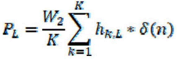
For example, the non-storyline ambisonic signal may be [ W2, 0, 0, 0] T. In this case, the virtual channel signal CK converted based on the non-storyline ambisonic signal may be represented by C1 ═ C2 ═ … ═ CK ═ W2/K. This is because the W component in the ambisonic signal is a signal component that has no directivity toward a specific direction in the virtual space. Thus, the non-storyline components PL and PR of the binaural rendered output audio signal may be represented by the sum of the filter coefficients of the binaural filter, the number of virtual channels, and W2, W2 being the value of the W signal component of the ambisonic signal. In addition, the above [ equation 5] can be represented by [ equation 6 ]. In [ equation 6], delta (n) may represent a delta function. Specifically, the delta function may include a unit pulse function having a magnitude of "1" at n ═ 0. In addition, in [ equation 6], K representing the number of virtual channels may be an integer.
[ equation 6]

According to an embodiment, when the layout of the virtual channels is symmetric with respect to the listener in the virtual space, the sum of the filter coefficients of the binaural filters corresponding to each ear of both ears of the listener may be the same. In the case of being based on a first virtual channel and a second virtual channel that are symmetrical to each other through a middle plane of a listener, a first on-side binaural filter corresponding to the first virtual channel may be the same as a second on-side binaural filter corresponding to the second virtual channel. In addition, the first pair of side binaural filters corresponding to the first virtual channel may be the same as the second ipsilateral binaural filters corresponding to the second virtual channel. Therefore, in a binaural rendered output audio signal, the non-scenario component PL of the left side output audio signal L 'and the non-scenario component PR of the right side output audio signal R' may be represented by the same audio signal. In addition, the above [ equation 6] can be represented by [ equation 7 ].
[ equation 7]

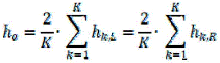
Here, h0Sigma (from)k=1ToK)hk,LSigma (from)k=1ToK)hk,R
In this case, when W2 is expressed as in [ equation 2] above, the output audio signal may be expressed based on the sum total of 2-channel stereo signals constituting the non-storyline channel signal. The output audio signal may be represented by [ equation 8 ].
[ equation 8]

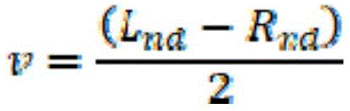
For example, the rendering apparatus 200 may restore a non-scenario channel signal composed of 2 channels based on the output audio signal of [ equation 8] and the differential signal v' described above. The non-scenario channel signal may be composed of a first channel signal Lnd and a second channel signal Rnd distinguished by channels. For example, the non-storyline channel signal may be a 2-channel stereo signal. In this case, the differential signal v may be a signal representing the difference between the first channel signal Lnd and the second channel signal Rnd. For example, the audio signal processing apparatus 100 may generate the differential signal v based on a difference between the first channel signal Lnd and the second channel signal Rnd for each time unit in the time domain. When the second channel signal Rnd is subtracted from the first channel signal Lnd, the differential signal v may be represented by [ equation 9 ].
[ equation 9]
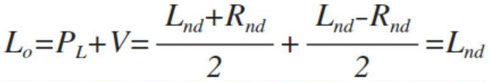
Further, the rendering apparatus 200 may synthesize the differential signal v ' received from the audio signal processing apparatus 100 with the output audio signals L ' and R ' to generate final output audio signals Lo ' and Ro '. For example, the rendering apparatus 200 may add the differential signal v 'to the left output audio signal L', and subtract the differential signal v 'from the right output audio signal R' to generate final output audio signals Lo 'and Ro'. In this case, the final output audio signals Lo 'and Ro' may include non-scenario channel signals Lnd and Rnd composed of 2 channels. The final output audio signal may be represented by [ equation 10 ]. When the non-scenario channel signal is a mono signal, a process in which the rendering apparatus 200 restores the non-scenario channel signal using the differential signal may be omitted.
[ equation 10]

Accordingly, the audio signal processing apparatus 100 may generate the non-scenario channel signal (W2, 0, 0, 0) based on the first filter described with reference to fig. 4. In addition, when the non-scenario channel signal is a 2-channel signal, the audio signal processing apparatus 100 may generate the differential signal v as in fig. 4. Through the above, the audio signal processing apparatus 100 may use an encoding stream of a number less than the sum of the number of signal components of the ambisonic audio signal and the number of channels of the non-scenario channel signal to transmit the scenario audio signal and the non-scenario audio signal included in the input audio signal to another apparatus. For example, the sum of the number of signal components of the ambisonic signal and the number of channels of the non-storic channel signal may be greater than the maximum number of encoded streams. In this case, the audio signal processing apparatus 100 may combine the non-scenario channel signal with the ambisonic signal to generate the encodable audio signal while including the non-scenario component.
Further, in the present embodiment, the rendering apparatus 200 is described as restoring the non-storyline channel signal using the difference between the sum of the signals, but the present disclosure is not limited thereto. When the non-scenario channel signal may be restored using a linear combination between audio signals, the audio signal processing apparatus 100 may generate and transmit an audio signal for restoration. In addition, the rendering apparatus 200 may restore the non-scenario channel signal based on the audio signal received from the audio signal processing apparatus 100.
In the embodiment of fig. 5, the binaural output audio signals rendered by the rendering apparatus 200 may be expressed as Lout and Rout of [ equation 11 ]. Equation 11 shows binaural rendered output audio signals Lout and Rout in the frequency domain. Additionally, W, X, Y and Z may each represent a frequency domain signal component of the FoA signal. Additionally, Hw, Hx, Hy, and Hz may be the frequency responses of the binaural filters corresponding to the W, X, Y and Z signal components, respectively. In this case, the binaural filter for each signal component corresponding to each signal component may be a plurality of elements constituting the above-described second filter. That is, the second filter may be represented by a combination of binaural filters corresponding to each signal component. In this disclosure, the frequency response of the binaural filter may be referred to as the binaural transfer function. Further, ". may denote a multiplication operation of a signal in the frequency domain.
[ equation 11]
Lout=W.Hw+X.Hx+Y.Hy+Z.Hz
Rout=W.Hw+X.Hx–Y.Hy+Z.Hz
As shown in [ equation 11], the binaural rendered output audio signal may be expressed as a product of binaural transfer functions Hw, Hx, Hy and each signal component in the Hz and frequency domain for each signal component. This is because the conversion and rendering of the ambisonic signal have a linear relationship. In addition, the first filter may be the same as an inverse filter of the binaural filter corresponding to the 0 th order signal component. This is because the non-storyline ambisonic signal does not contain a signal corresponding to another signal component other than the 0 th order signal component.
According to an embodiment, the rendering apparatus 200 may generate an output audio signal by performing channel rendering on the ambisonic signal B. In this case, the audio signal processing apparatus 100 may normalize the first filter such that the magnitude of the first filter is a constant frequency response. That is, the audio signal processing apparatus 100 may normalize at least one of the above-described binaural filter and its inverse filter corresponding to the 0 th order signal component. In this case, the first filter may be an inverse filter of a binaural filter corresponding to a predetermined signal component of the plurality of binaural filters for each signal component included in the second filter. In addition, the audio signal processing apparatus 100 may generate the non-storyline ambisonic signal by filtering the non-storic channel signal with a first filter having a frequency response of a constant size. When the magnitude of the frequency response of the first filter is not constant, the rendering apparatus 200 may not be able to recover the non-storyline channel signal. This is because, when the rendering apparatus 200 performs channel rendering on the stereo reverberation signal, the rendering apparatus 200 does not perform rendering based on the above-described second filter.
Hereinafter, for convenience of description, when the first filter is an inverse filter of a binaural filter corresponding to a predetermined signal component, operations of the audio signal processing apparatus 100 and the rendering apparatus 200 will be described with reference to fig. 6. This is merely for convenience of description, and the first filter may be an inverse filter of the entire second filter. In this case, the audio signal processing apparatus 100 may normalize the second filter such that a frequency response of a binaural filter corresponding to a predetermined signal component of the binaural filter for each signal component included in the second filter has a constant magnitude in the frequency domain. In addition, the audio signal processing apparatus 100 may generate the first filter based on the normalized second filter.
Fig. 6 is a schematic diagram illustrating a method for generating an output audio signal by a rendering apparatus 200 by channel-rendering an input audio signal including a non-storyline ambisonic signal according to an embodiment of the present disclosure. According to an embodiment, the rendering apparatus 200 may generate an output audio signal corresponding to each of a plurality of channels according to a channel layout. Specifically, the rendering apparatus 200 may channel-render the non-scenario channel signal based on position information indicating positions respectively corresponding to each of the plurality of channels according to a predetermined channel layout. In this case, the channel rendered output audio signal may include a number of channel signals determined according to a predetermined channel layout. When the ambisonic signal is the FoA signal, the decoding matrix T2 for converting the ambisonic signal into the speaker channel signal may be represented by [ equation 12 ].
[ equation 12]
T2=[t01 t11 t21 t31;
t02 t12 t22 t32;
…
t0K t1K t2K t3K]
In [ equation 12]]The number of columns of T2 may be determined based on the highest order of the ambisonic signal. Also, K may represent the number of speaker channels determined according to the channel layout. E.g. t0KMay represent a means for communicating FoAThe W signal component of the number is converted into an element of the K channel signal. In this case, the k channel signal CHk may be represented by equation 13]And (4) showing. In [ equation 13]]Ft (x) may mean a fourier transform function for converting an audio signal "x" in the time domain into a signal in the frequency domain. [ equation 13]]A signal in the frequency domain is represented, but the present disclosure is not limited thereto.
[ equation 13]
CHk=W1.t0k+X1.t1k+Y1.t2k+Z1.t3k+W2.t0k
=W1.t0k+X1.t1k+Y1.t2k+Z1.t3k+FT{(Lnd+Rnd)/2}.Hw-1.t0k
In [ equation 12]]W1, X1, Y1, and Z1 may respectively represent signal components of a ambisonic signal corresponding to a storyline audio signal. For example, W1, X1, Y1, and Z1 may be signal components of the first ambisonic signal obtained in step S302 of fig. 3. Also, in [ equation 13]]W2 may be a non-storyline ambisonic signal. When the non-storyline channel signal is composed of the first channel signal Lnd and the second channel signal Rnd distinguished by channels, W2 may be expressed as a value obtained by filtering a signal, which is obtained by synthesizing the first channel signal and the second channel signal, using the first filter, as [ equation 13]]As shown. In [ equation 13]]In because of Hw-1Is a filter generated based on the layout of the virtual channels, therefore Hw-1And t0kMay not be in an inverse relationship to each other. In this case, the rendering apparatus 200 cannot restore the same audio signal as the first input audio signal that has been input to the audio signal processing apparatus 100. Accordingly, the audio signal processing apparatus 100 may normalize the frequency domain response of the first filter to have a constant value. Specifically, the audio signal processing apparatus 100 may set the frequency response of the first filter to have a constant value "1". In this case, [ equation 13]]May be calculated in accordance with equation 14]In same way omit Hw-1Is shown in the format of (1). Through the above, the audio signal processing apparatus 100 can generate the first output audio signal, the first output audio signalAn output audio signal allows the rendering apparatus 200 to restore the same audio signal as the first input audio signal.
[ equation 14]
CHk=W1.t0k+X1.t1k+Y1.t2k+Z1.t3k+W2.t0k=W1.t0k+X1.t1k+Y1.t2k+Z1.t3k+FT{(Lnd+Rnd)/2}.t0k
Further, the rendering apparatus 200 may synthesize the differential signal v ' received from the audio signal processing apparatus 100 with the plurality of channel signals CH1, … …, CHk to generate second output audio signals CH1 ', … …, CHk '. Specifically, the rendering apparatus 200 may mix the differential signal v' and the plurality of channel signals CH1, … …, CHk based on position information indicating a position corresponding to each of the plurality of channels, respectively, according to a predetermined channel layout. The rendering apparatus 200 may mix each of the plurality of channel signals CH 1.
For example, the rendering apparatus 200 may determine whether to add or subtract the differential signal v' to or from the third channel signal based on the position information of the third channel signal, which is any one of the plurality of channel signals. Specifically, when the position information corresponding to the third channel signal represents the left side with respect to the middle plane in the virtual space, the rendering apparatus 200 may add the third channel signal and the differential signal v' to generate a final third channel signal. In this case, the final third channel signal may include the first channel signal Lnd. The middle plane may represent a plane perpendicular to a horizontal plane outputting the final output audio signal and having a predetermined channel layout having the same center as the horizontal plane.
Further, when the position information corresponding to the fourth channel signal represents the right side with respect to the middle plane in the virtual space, the rendering apparatus 200 may generate a final fourth channel signal based on the difference between the differential signal v' and the fourth channel signal. In this case, the fourth channel signal may be a signal corresponding to any one channel different from the third channel among the plurality of channel signals. The final fourth channel signal may include the second channel signal Rnd. Also, the position information of the fifth channel signal different from the third channel signal and the fourth channel signal may indicate a position on the middle plane. In this case, the rendering apparatus 200 may not mix the fifth channel signal and the differential signal v'. Equation 15 represents the final channel signal CHk' including each of the first channel signal Lnd and the second channel signal Rnd.
[ equation 15]
CHk’=W1.t0k+X1.t1k+Y1.t2k+Z1.t3k+FT{(Lnd+Rnd)/2}.t0k+FT{(Lnd-Rnd)/2}.t0k=W1.t0k+X1.t1k+Y1.t2k+Z1.t3k+FT{Lnd}.t0k
Or
CHk’=W1.t0k+X1.t1k+Y1.t2k+Z1.t3k+FT{(Lnd+Rnd)/2}.t0k-FT{(Lnd-Rnd)/2}.t0k=W1.t0k+X1.t1k+Y1.t2k+Z1.t3k+FT{Rnd}.t0k
In the above-described embodiment, the first channel and the second channel are described to correspond to each of the left and right sides with respect to the middle plane, but the present disclosure is not limited thereto. For example, the first channel and the second channel may be channels respectively corresponding to regions different from each other with respect to a plane dividing the virtual space into two regions.
Meanwhile, according to an embodiment, the rendering apparatus 200 may generate an output audio signal using a normalized binaural filter. For example, the rendering apparatus 200 may receive a ambisonic signal including a non-storic ambisonic signal generated based on the normalized first filter described above. For example, the rendering apparatus 200 may normalize a binaural transfer function corresponding to another order signal component based on a binaural transfer function corresponding to a 0 th order signal component of the ambisonic. In this case, the rendering apparatus 200 may binaural-render the ambisonic signal based on the binaural filter normalized in the same manner as the audio signal processing apparatus 100 normalizes the first filter. The normalized binaural filter may be signaled from one of the audio signal processing apparatus 100 and the rendering apparatus 200 to the other. Alternatively, the rendering apparatus 200 and the audio signal processing apparatus 100 may generate the normalized binaural filter in a common manner, respectively. Equation 16 represents an embodiment for normalizing the binaural filter. In [ equation 16], Hw0, Hx0, Hy0, and Hz0 may be binaural transfer functions corresponding to W, X, Y and Z signal components of the FoA signal, respectively. In addition, Hw, Hx, Hy, and Hz may be normalized binaural transfer functions for each signal component corresponding to W, X, Y and the Z signal component.
[ equation 16]
Hw=Hw0/Hw0
Hx=Hx0/Hw0
Hy=Hy0/Hw0
Hz=Hz0/Hw0
Such as [ equation 16]]As in (1), the normalized binaural filter may have a binaural transfer function in which a binaural transfer function for each signal component is divided by Hw that is a binaural transfer function corresponding to the predetermined signal component0In the form of (1). However, the normalization method is not limited thereto. For example, the rendering apparatus 200 may be based on | Hw0The magnitude of | is normalized to the binaural filter.
Meanwhile, in a small device such as a mobile device, it is difficult to support various encoding/decoding methods depending on limited computing power and memory size of the small device. This may be the same for some large and small devices. For example, at least one of the audio signal processing apparatus 100 and the rendering apparatus 200 may support only a 5.1-channel codec for encoding a 5.1-channel signal. In this case, the audio signal processing apparatus 100 may have difficulty in transmitting four or more object signals and 2-channel or more non-scenario channel signals together. In addition, when the rendering apparatus 200 receives data corresponding to the FoA signal and the 2-channel non-storyline channel signal, it may be difficult for the rendering apparatus 200 to render all received signal components. This is because the rendering apparatus 200 cannot decode the encoded streams of more than 5 encoded streams using the 5.1-channel codec.
The audio signal processing apparatus 100 according to an embodiment of the present disclosure may reduce the number of channels of the 2-channel non-scenario channel signal by the above-described method. Through the above, the audio signal processing apparatus 100 may transmit the audio data encoded using the 5.1-channel codec to the rendering apparatus 200. In this case, the audio data may include data for reproducing non-storyline sounds. Hereinafter, a method of the audio signal processing apparatus 100 transmitting a non-scenario signal composed of 2 channels and an FoA signal using a 5.1-channel codec encoding will be described with reference to fig. 7.
Fig. 7 is a schematic diagram illustrating an operation of the audio signal processing apparatus 100 when the audio signal processing apparatus 100 supports a codec for encoding a 5.1-channel signal according to an embodiment of the present disclosure. The 5.1-channel sound output system may represent a sound output system composed of a total of five full-band speakers and one woofer disposed at the front left and right, the center, and the rear left and right. In addition, the 5.1-channel codec may be a device for encoding/decoding an audio signal input or output to a corresponding sound output system. However, in the present disclosure, the audio signal processing apparatus 100 may encode/decode an audio signal using a 5.1-channel codec, instead of playback in a 5.1-channel sound output system. For example, in the present disclosure, the audio signal processing apparatus 100 may encode an audio signal having the same number of full band channel signals constituting the audio signal as the number of channel signals constituting the 5.1 channel signal using a 5.1 channel codec. Therefore, the signal component or channel signal corresponding to each of the five encoded streams may not be an audio signal output through the 5.1-channel sound output system.
Referring to fig. 7, the audio signal processing apparatus 100 may generate a first output audio signal based on a first FoA signal composed of four signal components and a non-scenario channel signal composed of 2 channels. In this case, the first output audio signal may be an audio signal composed of 5 signal components corresponding to 5 encoded streams. The audio signal processing apparatus 100 may generate the second FoA signal (w2, 0, 0, 0) based on the non-scenario channel signal. The audio signal processing apparatus 100 may synthesize the first FoA signal and the second FoA signal. Also, the audio signal processing apparatus 100 may assign each of four signal components of a signal obtained by synthesizing the first FoA signal and the second FoA signal to four encoded streams of a 5.1-channel codec. In addition, the audio signal processing apparatus 100 may assign a differential signal between the non-scenario channel signals to one encoded stream. The audio signal processing apparatus 100 may encode the first output audio signal assigned to each of the 5 encoded streams using a 5.1-channel codec. In addition, the audio signal processing apparatus 100 may transmit the encoded audio data to the rendering apparatus 200.
In addition, the rendering apparatus 200 may receive encoded audio data from the audio signal processing apparatus 100. The rendering apparatus 200 may decode audio data encoded based on a 5.1-channel codec to generate an input audio signal. The rendering apparatus 200 may output the second output audio signal by rendering the input audio signal.
Meanwhile, according to an embodiment, the audio signal processing apparatus 100 may receive an input audio signal including an object signal. In this case, the audio signal processing apparatus 100 may convert the object signal into a ambisonic signal. In this case, the highest order of the ambisonic signal may be less than or equal to the highest order of the first ambisonic signal included in the input audio signal. This is because when the output audio signal includes the object signal, the efficiency of encoding the audio signal and the efficiency of transmitting the encoded data may be reduced. For example, the audio signal processing apparatus 100 may include the object ambisonic converter 70. The process of fig. 7 may be implemented by a processor to be described later, as well as other operations of the audio signal processing apparatus 100.
Specifically, when the audio signal processing apparatus 100 performs encoding using an independent encoding stream for each object, encoding of the audio signal processing apparatus 100 may be limited according to an encoding method. This is because the number of encoded streams may be limited according to the encoding method. Accordingly, the audio signal processing apparatus 100 may convert the object signal into the ambisonic signal and then transmit the converted signal. This is because, in the case of the ambisonic signal, the number of signal components is limited to a predetermined number according to the order of the ambisonic format. For example, the audio signal processing apparatus 100 may convert the object signal into the ambisonic signal based on position information indicating a position of an object corresponding to the object signal.
Fig. 8 and 9 are block diagrams illustrating configurations of the audio signal processing apparatus 100 and the rendering apparatus 200 according to an embodiment of the present disclosure. Some components illustrated in fig. 8 and 9 may be omitted, and the audio signal processing apparatus 100 and the rendering apparatus 200 may further include components not shown in fig. 8 and 9. Further, each device may be integrally provided with at least two components different from each other. According to an embodiment, the audio signal processing apparatus 100 and the rendering apparatus 200 may be respectively implemented as a single semiconductor chip.
Referring to fig. 8, the audio signal processing apparatus 100 may include a transceiver 110 and a processor 120. The transceiver 110 may receive an input audio signal input to the audio signal processing apparatus 100. The transceiver 110 may receive an input audio signal to be subjected to audio signal processing by the processor 120. In addition, the transceiver 110 may transmit the output audio signal generated in the processor 120. Here, the input audio signal and the output audio signal may include at least one of a ambisonic signal and a channel signal.
According to an embodiment, the transceiver 110 may be provided with a transmitting/receiving device for transmitting/receiving an audio signal. For example, the transceiver 110 may include an audio signal input/output terminal for transmitting/receiving an audio signal transmitted through a wire. The transceiver 110 may include a wireless audio transmission/reception module for transmitting/receiving a wirelessly transmitted audio signal. In this case, the transceiver 110 may receive the wirelessly transmitted audio signal using a wireless communication method such as bluetooth or Wi-Fi.
According to an embodiment, when the audio signal processing apparatus 100 includes at least one of a separate encoder and decoder, the transceiver 110 may transmit/receive a bitstream in which an audio signal is encoded. In this case, the encoder and the decoder may be implemented by the processor 120, which will be described later. In particular, the transceiver 110 may include one or more components that are capable of communicating with another device external to the audio signal processing device 100. In this case, another apparatus may include the rendering apparatus 200. Further, the transceiver 110 may include at least one antenna for transmitting the encoded audio data to the rendering apparatus 200. Also, the transceiver 110 may be provided with hardware for wired communication for transmitting encoded audio data.
The processor 120 may control the overall operation of the audio signal processing apparatus 100. The processor 120 may control each component of the audio signal processing apparatus 100. The processor 120 may perform various data and signal operations and processes. The processor 120 may be implemented as hardware in the form of a semiconductor chip or an electronic circuit, or as software that controls the hardware. The processor 120 may be implemented in a form in which hardware and software are combined. For example, the processor 120 may control the operation of the transceiver 110 by executing at least one program included in software. Also, the processor 120 may execute at least one program to perform the operations of the audio signal processing apparatus 100 described with reference to fig. 1 to 7.
For example, the processor 120 may generate an output audio signal from an input audio signal received through the transceiver 110. In particular, the processor 120 may generate a non-storyline ambisonic signal based on the non-storyline channel signal. In this case, the non-storyline ambisonic signal may be a ambisonic signal including only a signal corresponding to a predetermined signal component among a plurality of signal components included in the ambisonic signal. Also, the processor 120 may generate a ambisonic signal whose signal of a signal component other than the predetermined signal component is zero. The processor 120 may filter the non-storyline channel signal using the first filter described above to generate a non-storyline ambisonic signal.
Further, the processor 120 may synthesize the non-storyline ambisonic signal and the input ambisonic signal to generate an output audio signal. In addition, when the non-scenario channel signal is composed of 2 channels, the processor 120 may generate a difference signal representing a difference between the channel signals composing the non-scenario channel signal. In this case, the output audio signal may include a difference signal and a ambisonic signal obtained by synthesizing the non-storic ambisonic signal and the input ambisonic signal. Also, the processor 120 may encode the output audio signal to generate encoded audio data. The processor 120 may transmit the generated audio data through the transceiver 110.
Referring to fig. 9, a rendering apparatus 200 according to an embodiment of the present disclosure may include a receiving unit 210, a processor 220, and an output unit 230. The receiving unit 210 may receive an input audio signal input to the rendering apparatus 200. The receiving unit 210 may receive an input audio signal to be subjected to audio signal processing by the processor 220. According to an embodiment, the receiving unit 210 may be provided with receiving means for receiving an audio signal. For example, the receiving unit 210 may include an audio signal input/output terminal for receiving an audio signal transmitted by wire. The receiving unit 210 may include a wireless audio receiving module for transmitting/receiving a wirelessly transmitted audio signal. In this case, the receiving unit 210 may receive the wirelessly transmitted audio signal using a wireless communication method such as bluetooth or Wi-Fi.
According to an embodiment, when the rendering apparatus 200 includes a separate decoder, the receiving unit 210 may transmit/receive a bitstream in which an audio signal is encoded. In this case, the decoder may be implemented by the processor 220 described later. In particular, the receiving unit 210 may include one or more components capable of communicating with another device external to the rendering device 200. In this case, the other apparatus may include the audio signal processing apparatus 100. Further, the receiving unit 210 may comprise at least one antenna for receiving encoded audio data from the audio signal processing device 100. Further, the receiving unit 210 may be provided with hardware for wired communication for receiving encoded audio data.
The processor 220 may control the overall operation of the rendering apparatus 200. The processor 220 may control each component of the rendering apparatus 200. Processor 220 may perform various data and signal operations and processes. The processor 220 may be implemented as hardware in the form of a semiconductor chip or electronic circuit, or as software that controls the hardware. The processor 220 may be implemented in a form in which hardware and software are combined. For example, the processor 220 may control the operations of the receiving unit 210 and the output unit 230 by executing at least one program included in software. Also, the processor 220 may execute at least one program to perform the operations of the rendering apparatus 200 described above with reference to fig. 1 to 7.
According to one embodiment, the processor 220 may generate the output audio signal by rendering the input audio signal. For example, the input audio signal may include a ambisonic signal and a differential signal. Here, the ambisonic signal may include the above-described non-scenario channel signal. In addition, the non-storyline ambisonic signal may be a signal generated based on the non-storyline channel signal. In addition, the difference signal may be a signal representing a difference between channel signals of a non-scenario channel signal composed of 2 channels. According to an embodiment, the processor 220 may binaural render the input audio signal. The processor 220 may binaural render the ambisonic signal to generate a 2-channel binaural audio signal corresponding to each of the listener's ears. In addition, the processor 220 may output an output audio signal generated by the output unit 230.
The output unit 230 may output an output audio signal. For example, the output unit 230 may output an output audio signal generated by the processor 220. The output unit 230 may include at least one output channel. Here, the output audio signal may be a 2-channel output audio signal corresponding to each of both ears of the listener. Here, the output audio signal may be a binaural 2-channel output audio signal. The output unit 230 may output the 3D audio headphone signal generated by the processor 220.
According to an embodiment, the output unit 230 may be provided with an output device for outputting an output audio signal. For example, the output unit 230 may include an output terminal for outputting an output audio signal to the outside. In this case, the rendering apparatus 200 may output the output audio signal to an external device connected to the output terminal. Alternatively, the output unit 230 may include a wireless audio transmitting/receiving module for outputting the output audio signal to the outside. In this case, the output unit 230 may output the output audio signal to the external device using a wireless communication method such as bluetooth or Wi-Fi. Alternatively, the output unit 230 may include a speaker. In this case, the rendering apparatus 200 may output the output audio signal through a speaker. Specifically, the output unit 230 may include a plurality of speakers arranged according to a predetermined channel layout. In addition, the output unit 230 may additionally include a converter (e.g., a digital-to-analog converter (DAC)) that converts a digital audio signal into an analog audio signal.
Some embodiments may also be implemented in the form of a recording medium including instructions executable by a computer, such as program modules, executed by a computer. Computer readable media can be any available media that can be accessed by the computer and includes both volatile and nonvolatile media, and removable and non-removable media. Additionally, computer readable media may include computer storage media. Computer storage media may include volatile and nonvolatile, and removable and non-removable media implemented in any method or technology for storage of information, such as computer readable instructions, data structures, program modules, or other data.
Further, in the present disclosure, a "unit" may be a hardware component such as a processor or a circuit, and/or a software component executed by a hardware component such as a processor.
Although the present disclosure has been described with reference to specific embodiments thereof, modifications and changes may be made by those skilled in the art without departing from the spirit and scope of the present disclosure. That is, although the present disclosure has been described with respect to embodiments in which binaural rendering is performed on an audio signal, the present disclosure is equally applicable and extendable to various multimedia signals including video signals as well as audio signals. Accordingly, it will be readily understood by those skilled in the art that various modifications and changes may be made thereto without departing from the spirit and scope of the present invention as defined by the appended claims.
Claims (19)
1. An audio signal processing apparatus for generating an output audio signal, the audio signal processing apparatus comprising a processor configured to:
obtaining an input audio signal comprising a first ambisonic signal and a non-storic channel signal (Lnd, Rnd);
generating a second ambisonic signal including only a signal corresponding to a predetermined signal component among a plurality of signal components included in a ambisonic format of the first ambisonic signal based on the non-plot channel signals (Lnd, Rnd); and is
Generating an output audio signal comprising a third ambisonic signal obtained by synthesizing the second and first ambisonic signals for each signal component,
wherein the non-storyline channel signal (Lnd, Rnd) represents an audio signal forming an audio scene fixed with respect to a listener, and the predetermined signal component is a signal component representing a sound pressure of a soundfield at a point where a ambisonic signal has been collected.
2. The audio signal processing apparatus of claim 1, wherein the processor is configured to filter the non-storyline channel signal with a first filter to generate the second ambisonic signal, and
wherein the first filter is an inverse filter of a second filter for binaural rendering of the third ambisonic signal as an output audio signal in an output device that has received the third ambisonic signal.
3. The audio signal processing apparatus of claim 2, wherein the processor is configured to obtain information on a plurality of virtual channels arranged in a virtual space in which the output audio signal is simulated, and to generate the first filter based on the information of the plurality of virtual channels, and
wherein information of the plurality of virtual channels is used to render the third ambisonic signal.
4. The audio signal processing apparatus according to claim 1, wherein the non-scenario channel signal is a 2-channel signal composed of a first channel signal and a second channel signal, and
wherein the processor is configured to generate a differential signal between the first channel signal and the second channel signal and to generate an output audio signal comprising the differential signal and the third ambisonic signal.
5. The audio signal processing apparatus of claim 4, wherein the processor is configured to encode the output audio signal to generate a bitstream and to transmit the generated bitstream to an output device,
wherein the output device is a device for rendering an audio signal generated by decoding the bitstream, and
wherein, when the number of encoded streams used to generate the bitstream is N, the output audio signal includes the third ambisonic signal composed of N-1 signal components corresponding to N-1 encoded streams and the differential signal corresponding to one encoded stream.
6. The audio signal processing apparatus of claim 5, wherein the maximum number of encoded streams supported by a codec used to generate the bitstream is five.
7. An audio signal processing apparatus for rendering an input audio signal, the audio signal processing apparatus comprising a processor configured to:
obtaining an input audio signal comprising a ambisonic signal and a non-storic channel difference signal (v);
rendering the ambisonic signal to generate a first output audio signal;
mixing the first output audio signal and the non-storyline channel difference signal (v) to generate a second output audio signal; and is
Outputting the second output audio signal;
wherein the non-scenario channel difference signal (v) is a difference signal representing a difference between a first channel signal and a second channel signal constituting a 2-channel audio signal, and the first channel signal and the second channel signal are both audio signals forming an audio scene fixed with respect to a listener, wherein the ambisonic signal includes a non-scenario ambisonic signal (W2) generated based on a signal obtained by synthesizing the first channel signal and the second channel signal,
wherein the non-storyline ambisonic signal (W2) includes only a signal corresponding to a predetermined signal component among a plurality of signal components included in a ambisonic format of the ambisonic signal, and
wherein the predetermined signal component is a signal component representing a sound pressure of a sound field at a point where the ambisonic signal has been collected.
8. The audio signal processing apparatus according to claim 7, wherein the non-storyline ambisonic signal is a signal obtained by filtering, with a first filter, a signal that has been obtained by synthesizing the first channel signal and the second channel signal, and
wherein the first filter is an inverse filter of a second filter for binaural rendering of the ambisonic signal as the first output audio signal.
9. The audio signal processing apparatus according to claim 8, wherein the first filter is generated based on information on a plurality of virtual channels arranged in a virtual space in which the first output audio signal is simulated.
10. The audio signal processing apparatus according to claim 9, wherein the information of the plurality of virtual channels includes position information representing a position of each of the plurality of virtual channels,
wherein the first filter is generated based on a plurality of binaural filters corresponding to a position of each of the plurality of virtual channels, and
wherein the plurality of binaural filters are determined based on the location information.
11. The audio signal processing apparatus of claim 10, wherein the first filter is generated based on a sum of filter coefficients included in the plurality of binaural filters.
12. The signal processing apparatus according to claim 11, wherein the first filter is generated based on a result of an inverse operation of a sum of the filter coefficients and the number of the plurality of virtual channels.
13. The audio signal processing apparatus of claim 10, wherein the processor is configured to: binaural rendering the ambisonic signal based on information of the plurality of virtual channels arranged in the virtual space to generate the first output audio signal; and is
Mixing the first output audio signal with the non-storyline channel difference signal to generate the second output audio signal.
14. The audio signal processing apparatus according to claim 8, wherein the second filter includes a plurality of binaural filters for each signal component corresponding respectively to each signal component included in the ambisonic signal (B3),
wherein the first filter is an inverse filter of a binaural filter corresponding to a predetermined signal component among the plurality of binaural filters for each signal component, and
wherein the frequency response of the first filter has a constant magnitude in the frequency domain.
15. The audio signal processing apparatus according to claim 7, wherein the second output audio signal includes a plurality of output audio signals respectively corresponding to each of a plurality of channels according to a predetermined channel layout, and
wherein the processor is configured to:
generating the first output audio signal comprising a plurality of output channel signals respectively corresponding to each of the plurality of channels by channel rendering the ambisonic signal (B3) based on position information representing a position respectively corresponding to each of the plurality of channels; and is
Generating, for each channel of a plurality of channels, the second output audio signal by mixing the first output audio signal and the non-storyline channel difference signal based on the position information,
wherein each of the plurality of output channel signals includes an audio signal obtained by synthesizing the first channel signal and the second channel signal.
16. The audio signal processing apparatus according to claim 15, wherein the intermediate plane represents a plane that is perpendicular to a horizontal plane of the predetermined channel layout and has the same center as the horizontal plane, and
wherein the processor is configured to generate the second output audio signal by differently mixing the non-storyline channel difference signal with the first output audio signal for each of a channel corresponding to a left side with respect to a middle plane, a channel corresponding to a right side with respect to the middle plane, and a channel corresponding to the middle plane among the plurality of channels.
17. The audio signal processing apparatus according to claim 7, wherein the first channel signal and the second channel signal are channel signals corresponding to different regions with respect to a plane that divides a virtual space in which the second output audio signal is simulated into two regions.
18. A method for operating an audio signal processing apparatus for rendering an input audio signal, the method comprising:
obtaining an input audio signal comprising a ambisonic signal and a non-storic channel difference signal (v);
rendering the ambisonic signal to generate a first output audio signal;
mixing the first output audio signal with the non-storyline channel difference signal (v) to generate a second output audio signal; and
outputting the second output audio signal and the second output audio signal,
wherein the non-scenario channel difference signal is a difference signal representing a difference between a first channel signal and a second channel signal constituting a 2-channel audio signal, and the first channel signal and the second channel signal are audio signals forming an audio scene fixed with respect to a listener,
wherein the ambisonic signal includes a non-storic ambisonic signal (W2) generated based on a signal obtained by synthesizing the first channel signal and the second channel signal,
wherein the non-storyline ambisonic signal (W2) includes only a signal corresponding to a predetermined signal component among a plurality of signal components included in a ambisonic format of the ambisonic signal, and
wherein the predetermined signal component is a signal component representing a sound pressure of a sound field at a point where the ambisonic signal has been collected.
19. An electronic device-readable recording medium in which a program for executing the method of claim 18 in an electronic device is recorded.
Applications Claiming Priority (5)
| Application Number | Priority Date | Filing Date | Title |
|---|---|---|---|
| KR20170103988 | 2017-08-17 | ||
| KR10-2017-0103988 | 2017-08-17 | ||
| KR20180055821 | 2018-05-16 | ||
| KR10-2018-0055821 | 2018-05-16 | ||
| PCT/KR2018/009285 WO2019035622A1 (en) | 2017-08-17 | 2018-08-13 | Audio signal processing method and apparatus using ambisonics signal |
Publications (2)
| Publication Number | Publication Date |
|---|---|
| CN111034225A CN111034225A (en) | 2020-04-17 |
| CN111034225B true CN111034225B (en) | 2021-09-24 |
Family
ID=65362897
Family Applications (1)
| Application Number | Title | Priority Date | Filing Date |
|---|---|---|---|
| CN201880052564.6A Active CN111034225B (en) | 2017-08-17 | 2018-08-13 | Audio signal processing method and apparatus using stereo reverberation signal |
Country Status (4)
| Country | Link |
|---|---|
| US (1) | US11308967B2 (en) |
| KR (1) | KR102128281B1 (en) |
| CN (1) | CN111034225B (en) |
| WO (1) | WO2019035622A1 (en) |
Families Citing this family (5)
| Publication number | Priority date | Publication date | Assignee | Title |
|---|---|---|---|---|
| CN111756929A (en) * | 2020-06-24 | 2020-10-09 | Oppo(重庆)智能科技有限公司 | Multi-screen terminal audio playing method and device, terminal equipment and storage medium |
| CN114067810B (en) * | 2020-07-31 | 2025-12-12 | 华为技术有限公司 | Audio signal rendering method and apparatus |
| WO2023274400A1 (en) * | 2021-07-02 | 2023-01-05 | 北京字跳网络技术有限公司 | Audio signal rendering method and apparatus, and electronic device |
| KR102687875B1 (en) * | 2021-07-19 | 2024-07-25 | 가우디오랩 주식회사 | Method and apparatus for switching an audio scene in a multi-view environment |
| TW202348047A (en) * | 2022-03-31 | 2023-12-01 | 瑞典商都比國際公司 | Methods and systems for immersive 3dof/6dof audio rendering |
Citations (13)
| Publication number | Priority date | Publication date | Assignee | Title |
|---|---|---|---|---|
| KR100737302B1 (en) * | 2003-10-02 | 2007-07-09 | 프라운호퍼-게젤샤프트 추르 푀르데룽 데어 안제반텐 포르슝 에 파우 | Compatible multi-channel coding/decoding |
| CN101166377A (en) * | 2006-10-17 | 2008-04-23 | 施伟强 | A low code rate coding and decoding scheme for multi-language circle stereo |
| CN101604524A (en) * | 2008-06-11 | 2009-12-16 | 北京天籁传音数字技术有限公司 | Stereo encoding method and device thereof, stereo decoding method and device thereof |
| CN101690269A (en) * | 2007-06-26 | 2010-03-31 | 皇家飞利浦电子股份有限公司 | A binaural object-oriented audio decoder |
| CN101828219A (en) * | 2007-09-06 | 2010-09-08 | Lg电子株式会社 | Method and device for decoding audio signal |
| CN104869523A (en) * | 2014-02-26 | 2015-08-26 | 北京三星通信技术研究有限公司 | Method, terminal and system for playing audio file through virtual multiple channel |
| CN104969571A (en) * | 2013-02-06 | 2015-10-07 | 华为技术有限公司 | Method for rendering a stereo signal |
| KR20160015245A (en) * | 2013-06-05 | 2016-02-12 | 톰슨 라이센싱 | Method for encoding audio signals, apparatus for encoding audio signals, method for decoding audio signals and apparatus for decoding audio signals |
| WO2016067007A1 (en) * | 2014-10-31 | 2016-05-06 | University Of Salford Enterprises Limited | Assistive mixing system and method of assembling a synchronised spatial sound stage |
| CN105578380A (en) * | 2011-07-01 | 2016-05-11 | 杜比实验室特许公司 | Systems and methods for adaptive audio signal generation, encoding and presentation |
| EP3075172A1 (en) * | 2013-11-28 | 2016-10-05 | Thomson Licensing | Method and apparatus for higher order ambisonics encoding and decoding using singular value decomposition |
| KR20170023017A (en) * | 2014-06-27 | 2017-03-02 | 돌비 인터네셔널 에이비 | Method and apparatus for determining for the compression of an hoa data frame representation a lowest integer number of bits required for representing non-differential gain values |
| CN106796794A (en) * | 2014-10-07 | 2017-05-31 | 高通股份有限公司 | The normalization of environment high-order ambiophony voice data |
Family Cites Families (5)
| Publication number | Priority date | Publication date | Assignee | Title |
|---|---|---|---|---|
| RU2407073C2 (en) * | 2005-03-30 | 2010-12-20 | Конинклейке Филипс Электроникс Н.В. | Multichannel audio encoding |
| KR100888474B1 (en) * | 2005-11-21 | 2009-03-12 | 삼성전자주식회사 | Apparatus and method for encoding/decoding multichannel audio signal |
| KR101439205B1 (en) * | 2007-12-21 | 2014-09-11 | 삼성전자주식회사 | METHOD AND APPARATUS FOR ENCODING AND DECODING AUDIO MATRIX |
| KR20090109489A (en) * | 2008-04-15 | 2009-10-20 | 엘지전자 주식회사 | Audio signal processing method and device thereof |
| WO2014163657A1 (en) * | 2013-04-05 | 2014-10-09 | Thomson Licensing | Method for managing reverberant field for immersive audio |
-
2018
- 2018-08-13 CN CN201880052564.6A patent/CN111034225B/en active Active
- 2018-08-13 WO PCT/KR2018/009285 patent/WO2019035622A1/en not_active Ceased
- 2018-08-13 KR KR1020187033032A patent/KR102128281B1/en active Active
-
2020
- 2020-02-07 US US16/784,259 patent/US11308967B2/en active Active
Patent Citations (13)
| Publication number | Priority date | Publication date | Assignee | Title |
|---|---|---|---|---|
| KR100737302B1 (en) * | 2003-10-02 | 2007-07-09 | 프라운호퍼-게젤샤프트 추르 푀르데룽 데어 안제반텐 포르슝 에 파우 | Compatible multi-channel coding/decoding |
| CN101166377A (en) * | 2006-10-17 | 2008-04-23 | 施伟强 | A low code rate coding and decoding scheme for multi-language circle stereo |
| CN101690269A (en) * | 2007-06-26 | 2010-03-31 | 皇家飞利浦电子股份有限公司 | A binaural object-oriented audio decoder |
| CN101828219A (en) * | 2007-09-06 | 2010-09-08 | Lg电子株式会社 | Method and device for decoding audio signal |
| CN101604524A (en) * | 2008-06-11 | 2009-12-16 | 北京天籁传音数字技术有限公司 | Stereo encoding method and device thereof, stereo decoding method and device thereof |
| CN105578380A (en) * | 2011-07-01 | 2016-05-11 | 杜比实验室特许公司 | Systems and methods for adaptive audio signal generation, encoding and presentation |
| CN104969571A (en) * | 2013-02-06 | 2015-10-07 | 华为技术有限公司 | Method for rendering a stereo signal |
| KR20160015245A (en) * | 2013-06-05 | 2016-02-12 | 톰슨 라이센싱 | Method for encoding audio signals, apparatus for encoding audio signals, method for decoding audio signals and apparatus for decoding audio signals |
| EP3075172A1 (en) * | 2013-11-28 | 2016-10-05 | Thomson Licensing | Method and apparatus for higher order ambisonics encoding and decoding using singular value decomposition |
| CN104869523A (en) * | 2014-02-26 | 2015-08-26 | 北京三星通信技术研究有限公司 | Method, terminal and system for playing audio file through virtual multiple channel |
| KR20170023017A (en) * | 2014-06-27 | 2017-03-02 | 돌비 인터네셔널 에이비 | Method and apparatus for determining for the compression of an hoa data frame representation a lowest integer number of bits required for representing non-differential gain values |
| CN106796794A (en) * | 2014-10-07 | 2017-05-31 | 高通股份有限公司 | The normalization of environment high-order ambiophony voice data |
| WO2016067007A1 (en) * | 2014-10-31 | 2016-05-06 | University Of Salford Enterprises Limited | Assistive mixing system and method of assembling a synchronised spatial sound stage |
Non-Patent Citations (2)
| Title |
|---|
| Ambisonics声像重放的优化方法研究;朱蓉;《中国优秀硕士学位论文全文数据库 信息科技辑》;20160315;全文 * |
| Efficient realization of model-based rendering for 2.5-dimensional near-field compensated higher order Ambisonics;Sascha Spors;《2011 IEEE Workshop on Applications of Signal Processing to Audio and Acoustics (WASPAA)》;20111118;全文 * |
Also Published As
| Publication number | Publication date |
|---|---|
| WO2019035622A1 (en) | 2019-02-21 |
| US11308967B2 (en) | 2022-04-19 |
| KR102128281B1 (en) | 2020-06-30 |
| US20200175997A1 (en) | 2020-06-04 |
| KR20190019915A (en) | 2019-02-27 |
| CN111034225A (en) | 2020-04-17 |
Similar Documents
| Publication | Publication Date | Title |
|---|---|---|
| US12165656B2 (en) | Encoding of a multi-channel audio signal to generate binaural signal and decoding of an encoded binauralsignal | |
| US11308967B2 (en) | Audio signal processing method and apparatus using ambisonics signal | |
| US9973874B2 (en) | Audio rendering using 6-DOF tracking | |
| KR101054932B1 (en) | Dynamic Decoding of Stereo Audio Signals | |
| US12494212B2 (en) | Audio encoding and decoding method and apparatus | |
| CN101356573B (en) | Control over decoding of binaural audio signals | |
| US8379868B2 (en) | Spatial audio coding based on universal spatial cues | |
| US9219972B2 (en) | Efficient audio coding having reduced bit rate for ambient signals and decoding using same | |
| US9794686B2 (en) | Controllable playback system offering hierarchical playback options | |
| CN114067810B (en) | Audio signal rendering method and apparatus | |
| CN110234060B (en) | Renderer controlled spatial upmix | |
| CN111492427A (en) | Priority information for higher order ambisonic audio data | |
| CN114582357B (en) | Audio encoding and decoding method and device | |
| US10075802B1 (en) | Bitrate allocation for higher order ambisonic audio data | |
| JP5227946B2 (en) | Filter adaptive frequency resolution | |
| US20190110148A1 (en) | Spatial relation coding of higher order ambisonic coefficients | |
| CN101433099A (en) | Personalized decoding of multi-channel surround sound | |
| WO2022262758A1 (en) | Audio rendering system and method and electronic device | |
| WO2022262750A1 (en) | Audio rendering system and method, and electronic device | |
| EP3808106A1 (en) | Spatial audio capture, transmission and reproduction | |
| CN118475978A (en) | Apparatus, method and computer program for enabling rendering of spatial audio | |
| US20240404531A1 (en) | Method and System for Coding Audio Data | |
| CN108206983B (en) | Encoder and method for three-dimensional sound signal compatible with existing audio and video system | |
| KR101319892B1 (en) | A method for modeling head-related transfer function for implementing 3d virtual sound, and method and apparatus for implementing 3d virtual sound using the same | |
| US20250104719A1 (en) | Method and System for Producing an Augmented Ambisonic Format |
Legal Events
| Date | Code | Title | Description |
|---|---|---|---|
| PB01 | Publication | ||
| PB01 | Publication | ||
| SE01 | Entry into force of request for substantive examination | ||
| SE01 | Entry into force of request for substantive examination | ||
| GR01 | Patent grant | ||
| GR01 | Patent grant |