CN111033546A - Electronic card and electronic card operation method - Google Patents
Electronic card and electronic card operation method Download PDFInfo
- Publication number
- CN111033546A CN111033546A CN201880055094.9A CN201880055094A CN111033546A CN 111033546 A CN111033546 A CN 111033546A CN 201880055094 A CN201880055094 A CN 201880055094A CN 111033546 A CN111033546 A CN 111033546A
- Authority
- CN
- China
- Prior art keywords
- information
- selection
- electronic card
- card
- payment
- Prior art date
- Legal status (The legal status is an assumption and is not a legal conclusion. Google has not performed a legal analysis and makes no representation as to the accuracy of the status listed.)
- Withdrawn
Links
Images


Classifications
-
- G—PHYSICS
- G06—COMPUTING OR CALCULATING; COUNTING
- G06Q—INFORMATION AND COMMUNICATION TECHNOLOGY [ICT] SPECIALLY ADAPTED FOR ADMINISTRATIVE, COMMERCIAL, FINANCIAL, MANAGERIAL OR SUPERVISORY PURPOSES; SYSTEMS OR METHODS SPECIALLY ADAPTED FOR ADMINISTRATIVE, COMMERCIAL, FINANCIAL, MANAGERIAL OR SUPERVISORY PURPOSES, NOT OTHERWISE PROVIDED FOR
- G06Q20/00—Payment architectures, schemes or protocols
- G06Q20/30—Payment architectures, schemes or protocols characterised by the use of specific devices or networks
- G06Q20/34—Payment architectures, schemes or protocols characterised by the use of specific devices or networks using cards, e.g. integrated circuit [IC] cards or magnetic cards
- G06Q20/356—Aspects of software for card payments
- G06Q20/3563—Software being resident on card
-
- G—PHYSICS
- G06—COMPUTING OR CALCULATING; COUNTING
- G06K—GRAPHICAL DATA READING; PRESENTATION OF DATA; RECORD CARRIERS; HANDLING RECORD CARRIERS
- G06K19/00—Record carriers for use with machines and with at least a part designed to carry digital markings
- G06K19/06—Record carriers for use with machines and with at least a part designed to carry digital markings characterised by the kind of the digital marking, e.g. shape, nature, code
- G06K19/067—Record carriers with conductive marks, printed circuits or semiconductor circuit elements, e.g. credit or identity cards also with resonating or responding marks without active components
- G06K19/07—Record carriers with conductive marks, printed circuits or semiconductor circuit elements, e.g. credit or identity cards also with resonating or responding marks without active components with integrated circuit chips
- G06K19/0701—Record carriers with conductive marks, printed circuits or semiconductor circuit elements, e.g. credit or identity cards also with resonating or responding marks without active components with integrated circuit chips at least one of the integrated circuit chips comprising an arrangement for power management
- G06K19/0702—Record carriers with conductive marks, printed circuits or semiconductor circuit elements, e.g. credit or identity cards also with resonating or responding marks without active components with integrated circuit chips at least one of the integrated circuit chips comprising an arrangement for power management the arrangement including a battery
- G06K19/0705—Record carriers with conductive marks, printed circuits or semiconductor circuit elements, e.g. credit or identity cards also with resonating or responding marks without active components with integrated circuit chips at least one of the integrated circuit chips comprising an arrangement for power management the arrangement including a battery the battery being connected to a power saving arrangement
-
- G—PHYSICS
- G06—COMPUTING OR CALCULATING; COUNTING
- G06K—GRAPHICAL DATA READING; PRESENTATION OF DATA; RECORD CARRIERS; HANDLING RECORD CARRIERS
- G06K19/00—Record carriers for use with machines and with at least a part designed to carry digital markings
- G06K19/06—Record carriers for use with machines and with at least a part designed to carry digital markings characterised by the kind of the digital marking, e.g. shape, nature, code
- G06K19/067—Record carriers with conductive marks, printed circuits or semiconductor circuit elements, e.g. credit or identity cards also with resonating or responding marks without active components
- G06K19/07—Record carriers with conductive marks, printed circuits or semiconductor circuit elements, e.g. credit or identity cards also with resonating or responding marks without active components with integrated circuit chips
- G06K19/077—Constructional details, e.g. mounting of circuits in the carrier
- G06K19/07701—Constructional details, e.g. mounting of circuits in the carrier the record carrier comprising an interface suitable for human interaction
- G06K19/07703—Constructional details, e.g. mounting of circuits in the carrier the record carrier comprising an interface suitable for human interaction the interface being visual
-
- G—PHYSICS
- G06—COMPUTING OR CALCULATING; COUNTING
- G06Q—INFORMATION AND COMMUNICATION TECHNOLOGY [ICT] SPECIALLY ADAPTED FOR ADMINISTRATIVE, COMMERCIAL, FINANCIAL, MANAGERIAL OR SUPERVISORY PURPOSES; SYSTEMS OR METHODS SPECIALLY ADAPTED FOR ADMINISTRATIVE, COMMERCIAL, FINANCIAL, MANAGERIAL OR SUPERVISORY PURPOSES, NOT OTHERWISE PROVIDED FOR
- G06Q20/00—Payment architectures, schemes or protocols
- G06Q20/22—Payment schemes or models
- G06Q20/227—Payment schemes or models characterised in that multiple accounts are available, e.g. to the payer
-
- G—PHYSICS
- G06—COMPUTING OR CALCULATING; COUNTING
- G06Q—INFORMATION AND COMMUNICATION TECHNOLOGY [ICT] SPECIALLY ADAPTED FOR ADMINISTRATIVE, COMMERCIAL, FINANCIAL, MANAGERIAL OR SUPERVISORY PURPOSES; SYSTEMS OR METHODS SPECIALLY ADAPTED FOR ADMINISTRATIVE, COMMERCIAL, FINANCIAL, MANAGERIAL OR SUPERVISORY PURPOSES, NOT OTHERWISE PROVIDED FOR
- G06Q20/00—Payment architectures, schemes or protocols
- G06Q20/30—Payment architectures, schemes or protocols characterised by the use of specific devices or networks
- G06Q20/34—Payment architectures, schemes or protocols characterised by the use of specific devices or networks using cards, e.g. integrated circuit [IC] cards or magnetic cards
- G06Q20/341—Active cards, i.e. cards including their own processing means, e.g. including an IC or chip
-
- G—PHYSICS
- G06—COMPUTING OR CALCULATING; COUNTING
- G06Q—INFORMATION AND COMMUNICATION TECHNOLOGY [ICT] SPECIALLY ADAPTED FOR ADMINISTRATIVE, COMMERCIAL, FINANCIAL, MANAGERIAL OR SUPERVISORY PURPOSES; SYSTEMS OR METHODS SPECIALLY ADAPTED FOR ADMINISTRATIVE, COMMERCIAL, FINANCIAL, MANAGERIAL OR SUPERVISORY PURPOSES, NOT OTHERWISE PROVIDED FOR
- G06Q20/00—Payment architectures, schemes or protocols
- G06Q20/30—Payment architectures, schemes or protocols characterised by the use of specific devices or networks
- G06Q20/34—Payment architectures, schemes or protocols characterised by the use of specific devices or networks using cards, e.g. integrated circuit [IC] cards or magnetic cards
- G06Q20/352—Contactless payments by cards
-
- G—PHYSICS
- G06—COMPUTING OR CALCULATING; COUNTING
- G06Q—INFORMATION AND COMMUNICATION TECHNOLOGY [ICT] SPECIALLY ADAPTED FOR ADMINISTRATIVE, COMMERCIAL, FINANCIAL, MANAGERIAL OR SUPERVISORY PURPOSES; SYSTEMS OR METHODS SPECIALLY ADAPTED FOR ADMINISTRATIVE, COMMERCIAL, FINANCIAL, MANAGERIAL OR SUPERVISORY PURPOSES, NOT OTHERWISE PROVIDED FOR
- G06Q20/00—Payment architectures, schemes or protocols
- G06Q20/30—Payment architectures, schemes or protocols characterised by the use of specific devices or networks
- G06Q20/34—Payment architectures, schemes or protocols characterised by the use of specific devices or networks using cards, e.g. integrated circuit [IC] cards or magnetic cards
- G06Q20/357—Cards having a plurality of specified features
- G06Q20/3574—Multiple applications on card
-
- G—PHYSICS
- G07—CHECKING-DEVICES
- G07F—COIN-FREED OR LIKE APPARATUS
- G07F7/00—Mechanisms actuated by objects other than coins to free or to actuate vending, hiring, coin or paper currency dispensing or refunding apparatus
- G07F7/08—Mechanisms actuated by objects other than coins to free or to actuate vending, hiring, coin or paper currency dispensing or refunding apparatus by coded identity card or credit card or other personal identification means
- G07F7/0806—Details of the card
- G07F7/0813—Specific details related to card security
- G07F7/0826—Embedded security module
-
- G—PHYSICS
- G07—CHECKING-DEVICES
- G07F—COIN-FREED OR LIKE APPARATUS
- G07F7/00—Mechanisms actuated by objects other than coins to free or to actuate vending, hiring, coin or paper currency dispensing or refunding apparatus
- G07F7/08—Mechanisms actuated by objects other than coins to free or to actuate vending, hiring, coin or paper currency dispensing or refunding apparatus by coded identity card or credit card or other personal identification means
- G07F7/0806—Details of the card
- G07F7/0846—On-card display means
-
- G—PHYSICS
- G07—CHECKING-DEVICES
- G07F—COIN-FREED OR LIKE APPARATUS
- G07F7/00—Mechanisms actuated by objects other than coins to free or to actuate vending, hiring, coin or paper currency dispensing or refunding apparatus
- G07F7/08—Mechanisms actuated by objects other than coins to free or to actuate vending, hiring, coin or paper currency dispensing or refunding apparatus by coded identity card or credit card or other personal identification means
- G07F7/0806—Details of the card
- G07F7/0853—On-card keyboard means
-
- G—PHYSICS
- G07—CHECKING-DEVICES
- G07F—COIN-FREED OR LIKE APPARATUS
- G07F7/00—Mechanisms actuated by objects other than coins to free or to actuate vending, hiring, coin or paper currency dispensing or refunding apparatus
- G07F7/08—Mechanisms actuated by objects other than coins to free or to actuate vending, hiring, coin or paper currency dispensing or refunding apparatus by coded identity card or credit card or other personal identification means
- G07F7/10—Mechanisms actuated by objects other than coins to free or to actuate vending, hiring, coin or paper currency dispensing or refunding apparatus by coded identity card or credit card or other personal identification means together with a coded signal, e.g. in the form of personal identification information, like personal identification number [PIN] or biometric data
- G07F7/1008—Active credit-cards provided with means to personalise their use, e.g. with PIN-introduction/comparison system
Landscapes
- Engineering & Computer Science (AREA)
- Business, Economics & Management (AREA)
- Physics & Mathematics (AREA)
- General Physics & Mathematics (AREA)
- Microelectronics & Electronic Packaging (AREA)
- Theoretical Computer Science (AREA)
- Accounting & Taxation (AREA)
- Strategic Management (AREA)
- General Business, Economics & Management (AREA)
- Computer Networks & Wireless Communication (AREA)
- Computer Hardware Design (AREA)
- Computer Security & Cryptography (AREA)
- Credit Cards Or The Like (AREA)
- Financial Or Insurance-Related Operations Such As Payment And Settlement (AREA)
- Control Of Vending Devices And Auxiliary Devices For Vending Devices (AREA)
Abstract
The electronic card of the present invention includes: a plate-shaped (plate type) card (card plate); a security element (secure element) embedded in the (embedded) plate-shaped card board and storing a plurality of application programs related to the payment mode; a control part for identifying one of the plurality of application programs and generating payment mode activation information based on the selection signal received by the selection part formed on the card board; and a display part displaying information identifying the payment method based on the payment method activation information. The control unit stores the plurality of application information provided based on the security element in association with the selection signal, manages the application identified based on the selection signal as the selected application, and generates payment method activation information.
Description
Technical Field
The present invention relates to an electronic card and a method of operating an electronic card capable of selectively activating payment mode related applications already stored in a secure element of a physical electronic card.
Background
With the diversification of payment means, methods for paying with an application in an intelligent device such as a mobile electronic device have recently come to be provided. However, payment methods that utilize applications running on smart devices are also based fundamentally on physical plastic cards, such as credit or debit cards, correlating information obtained from the smart device to information of the credit or debit card to make the payment.
A recent trend in the manufacture of credit or debit cards is for electronic cards that contain integrated circuit chips therein. Such electronic cards are also called Smart cards (Smart cards). The electronic card has a self-operation function and can be used in various ways. In particular, it has advantages of excellent safety and large storage capacity.
Disclosure of Invention
Technical problem
The invention provides an electronic card and an operation method thereof, which selectively activate an application program related to a payment mode in a security element in the card by using a plurality of card selection buttons arranged in a platy card.
The invention provides an electronic card and an operation method thereof, which can manage internally set payment mode information by setting a payment mode by using a plurality of card selection buttons through a battery in a platy card.
The invention provides an electronic card and an operation method thereof, which display information for identifying a payment mode selected by a plurality of card selection buttons through a display, so that the value selected by the plurality of card selection buttons does not have a fixed value and can be changed in various ways according to needs.
Technical scheme
The electronic card of the present invention includes: a plate-shaped (plate type) card (card plate); a security element (security) embedded (embedded) in the plate-shaped card and storing a plurality of applications related to payment means; a control part for identifying one of the plurality of application programs and generating payment mode activation information based on the selection signal received by the selection part formed on the card board; and a display unit that displays information for identifying a payment method based on the payment method activation information. The control unit may be configured to generate the payment method activation information by managing an application identified based on the selection signal as a selected application as a result of the selection signal being stored in association with a plurality of pieces of application information provided based on the secure element, and the secure element may be configured to receive the payment method activation information from the control unit to activate the selected application when a payment is attempted from outside.
In one embodiment, the electronic card further includes: and a power supply formed on the card board, activated independently of card payment, and supplying power to the control unit and the selection unit to drive transmission and reception of the selection signal.
In one embodiment, the plurality of application information provided by the security element to the control part includes at least one of an index (index) of each application, information displayed on the display part to identify each application, and a payment means description associated with each application.
In one embodiment, the secure element requests the payment method activation information from the control part in response to an external payment request.
In one embodiment, the secure element transmits the changed application information to the control section in response to a change in the plurality of application information.
In one embodiment, the control unit displays information identifying the payment method set based on the payment method activation information on the display unit as the power supply starts supplying power.
In one embodiment, the control unit displays information identifying the payment methods associated with the plurality of applications on the display unit in response to a selection signal of the selection unit.
In one embodiment, the selection part includes at least one of upper, lower, left, and right selection elements for sequentially selecting the plurality of applications.
In one embodiment, the control unit enters a sleep mode if there is no input from the selection unit within a preset time from the time when the power supply starts supplying power.
According to various embodiments of the present invention, the electronic card further includes an activation control portion formed on the card board and controlling power supply activation.
In one embodiment, the control unit enters the sleep mode if an input for activating the control unit is received within the preset time from a power supply start point.
In one embodiment, the control unit may match the index information in the application information with the selection signal.
An electronic card operating method according to an embodiment of the present invention is performed with an electronic card including a security element embedded in a plate-shaped card board.
An electronic card operating method according to an embodiment of the present invention includes the steps of: the security element transmits information of the set plurality of applications to the control part; the secure element requesting information of an application selected from the plurality of applications to the control part in response to an external payment request; the security element activates a respective application based on the selected application information.
The method of operating an electronic card of various embodiments of the present invention further comprises the steps of: the control unit manages by matching a plurality of application information received from the security element with a selection signal received by a selection unit formed in the card.
The method of operating an electronic card of various embodiments of the present invention further comprises the steps of: the control unit identifies one selected application program from the plurality of application programs based on the selection signal and generates payment method activation information.
In one embodiment, the method for operating the electronic card further includes the steps of: the secure element receiving a response based on the transmission of the plurality of application information from the control section; and the safety element transmits the plurality of application program information based on the application program version information included in the response of the control part.
In one embodiment, the method for operating the electronic card includes the following steps: a power supply formed on the plate-shaped card board supplies power to the control part and the selection part in response to the input of the activation control part; the control part responds to the input of the activation control part formed on the plate-shaped card board and starts to calculate the preset time; the control part enters a sleep mode in the preset time without an input of the selection part or receiving an input of the activation control part.
The method of operating an electronic card of various embodiments of the present invention comprises the steps of: the control part initializes calculation of the preset time when the input of the selection part is received within the preset time.
The method of operating an electronic card of various embodiments of the present invention further comprises the steps of: the control unit displays information identifying a payment method associated with the selected application program through a display unit formed on the card.
A program stored on a medium is included for causing a method according to an embodiment of the present invention to run on a computer.
The present invention includes a recording medium readable by a program recorded thereon for executing a method according to an embodiment of the present invention on a computer.
Technical effects
According to the electronic card and the operating method of the electronic card of the present invention, the payment method is selected by the selection part formed on the plate-shaped physical card, so that the effect that the user like the electronic card carries a plurality of cards is achieved. That is, the user of the electronic card can select the main payment mode from the plurality of payment modes of the electronic card, so that the inconvenience that the user of the electronic card needs to carry a plurality of cards can be reduced.
Furthermore, the electronic card and the electronic card operating method according to the present invention can select a payment method by a selection unit formed on the plate-shaped physical card and change the selected payment method according to the selection method of the selection unit.
The electronic card and the electronic card operating method of the present invention can flexibly change the payment mode related to the selection part formed on the electronic card. The electronic card and the electronic card operating method do not expose information with safety requirements in the process of selecting a plurality of payment modes, so that the safety can be improved.
According to the electronic card and the electronic card operation method, the payment mode can be set through the battery in the card, and power can be supplied from the outside of the card. Therefore, power can be flexibly consumed as needed.
Drawings
Fig. 1 shows an external appearance of an electronic card according to an embodiment of the present invention.
Fig. 2 and 3 are block diagrams for explaining an internal structure of an electronic card of the embodiment of the present invention.
Fig. 4 shows a case where the selection unit of the electronic card of the present invention is represented by a plurality of selection elements for identifying the form of the pattern.
Fig. 5a to 5c exemplarily show preset patterns recognized by the selection part provided to the electronic card of fig. 4.
Fig. 6 to 8 show a selection portion of an electronic card according to a plurality of embodiments of the present invention.
FIG. 9 is a flow chart for explaining an operation method of the electronic card according to an embodiment of the present invention.
Fig. 10 and 11 are flowcharts for explaining an operation method of an electronic card according to an embodiment of the present invention.
Best mode for carrying out the invention
Hereinafter, preferred embodiments of the present invention will be described in detail with reference to the accompanying drawings in order to clarify the technical idea of the present invention. In describing the present invention, it is judged that detailed description of related known structures or members may unnecessarily obscure the gist of the present invention, and the detailed description is omitted. In the drawings, members having substantially the same functional configurations are denoted by the same reference numerals and symbols as much as possible even when they are shown in different drawings. For convenience of description, the apparatus and method are described together as necessary.
Fig. 1 shows an external appearance of an electronic card according to an embodiment of the present invention, and fig. 2 is a block diagram for explaining an internal structure of the electronic card according to the embodiment of the present invention.
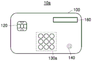
Referring to fig. 1, an electronic card 10 according to an embodiment of the present invention is seen from the outside, and an IC chip 120, a selection unit 130, an activation control unit 140, and a display 160 are seen.
First, the operation of the electronic card 10 viewed from the outside will be described, and specific internal components of the electronic card performing such operation will be described with reference to the plurality of electronic cards 20, 20' of fig. 2 and 3.
The electronic card 10 of an embodiment of the present invention may be a plate-shaped physical card. For example, the electronic card 10 may have a plate-like physical form such as a plastic material or a metal material, and may have the IC chip 120 to store information on a plurality of payment methods. Accordingly, information necessary for the payment method issued by a plurality of card issuers is stored in the IC chip 120. In the present invention, the IC chip 120 communicates with an external terminal in a contact or non-contact manner, and specifically, the IC chip 120 may communicate with a card reader in a contact manner and transmit or receive power, and may also operate in a non-contact manner based on a power source generated by a wireless signal. Although described later with reference to fig. 2 and 3, the IC chip 120 of the present invention is only one implementation of the security element 220.
The electronic card 10 may include a selection part 130 formed at a plate-shaped card. In the present invention, one of the payment means stored in the IC chip (120, the security element 220 of fig. 2 and 3) may be selected as a main payment card according to the selection of the selection unit 130.
According to an embodiment, the selection part 130 may be implemented in various forms. For example, the selection unit 130 may include one or more mechanical or electrical buttons, a touch panel, or the like, and may be a means for recognizing whether or not selection is made by an external user input.
Various examples of the selection section 130 will be described later with reference to fig. 4 to 8.
According to the embodiment, the selection unit 130 has a function of selecting a plurality of functions such as OTP (One Time Password) request means, card user registration means, card deactivation (lock) means, validity period/user/CVC card information display request means, and the like, in addition to a function of selecting One payment method from among a plurality of payment methods.
The electronic card 10 of the present invention has an activation control unit 140 and can set a payment method. In response to an input received by the activation control portion 140, the electronic card 10 supplies power to other components in the electronic card 10 through its own power supply. For example, the power supply inside the electronic card 10 supplies power to the components for selecting the payment method, specifically, the control unit 210 and the selection unit 230 shown in fig. 2 and 3.
The activation control unit 140, like the selection unit 130, is represented as a means including one or more mechanical or electrical buttons, a touch panel, and the like to recognize whether or not ON/OFF is activated by an external user input.
The electronic card 10 further includes a display unit 160 for displaying information identifying the payment method selected by the selection unit 130. For example, if fixed information is not displayed in the selection unit 130, the user cannot know what payment method is selected when selecting through the selection unit 130. The electronic card 10 of the present invention has a display unit 160 for displaying feedback (feedback) on operations including selection to the user, and displays information for identifying the payment method selected by the user to confirm the result of selection by the user.
The display unit 160 displays which payment method is set, and may display various information such as status information (setting error, sleep, power ON/OFF, payment response) of the electronic card 10, the OTP number, and card verification information (validity period, CVC number) described above.
The Display unit 160 includes a member capable of visually displaying information, such as a black-and-white or color LCD (Liquid Crystal Display), an LED (Light Emitting Display), and an EPD (Electronic Paper Display).
According to the embodiment, the payment method selected by the selection part 130 may be changed as desired. When the electronic card 10 executes different functions according to a setting process, a payment process, or the like, the function selected by giving a specific input to the selection unit 130 can be confirmed by the display unit 160. Therefore, the user can easily confirm the function of the selection part 130 by applying one physical electronic card 10 to a plurality of systems according to the setting of the user or the manufacturer, thereby improving the user convenience.
Referring to fig. 2, the electronic card 20 may include a control part 210, a security element 220, a selection part 230, an activation control part 240, a power supply 250, and a display part 260.
The control Unit 210 may include a Micro Controller Unit (MCU) in the form of a printed circuit or a chip interposed between an upper cover sheet and a lower cover sheet forming the electronic card 10 in a plate shape. The control part 210 operates by receiving power from the power supply 250 according to an input of the activation control part 240, or operates by power generated based on a wireless signal provided from the outside.
The control unit 210 has a storage means and manages the payment method in accordance with the selection signal input to the selection unit 230. The payment method selected according to the selection signal input through the selection part 230 is determined by the security element 220 or another input provided by the control part 210. In the electronic card 20 of the present invention, the payment method matching the selection signal input through the selection unit 230 is determined at the time of manufacture or is changed according to the security element 220 after manufacture.
The control unit 210 is electrically connected to the selection unit 230, and can receive a selection signal from the selection unit 230 and determine which payment method is selected based on the selection signal.
The control unit 210 waits for the selection signal from the selection unit 230 to be received for a preset time, and may enter a sleep mode (sleep mode) when there is no input from the selection unit 230 for the preset time. The control unit 210 enters the sleep mode to prevent the power supply 250 of the electronic card 20 from being consumed.
According to an embodiment, the control part 210 and the selection part 230 are connected to each other by a circuit pattern, respectively, based on a printed circuit interposed between an upper cover sheet and a lower cover sheet of a plate-shaped electronic card. When the control unit 210 and the selection unit 230 are connected by the circuit pattern, a selection signal, which is a different electrical signal when the selection unit 230 is selected, is supplied to the control unit 210 by the circuit pattern, so that the control unit 210 can recognize which selection has occurred in the selection unit 230.
For example, the control section 210 operates based on an inherent synchronization signal. The different synchronization signals generated by the selection of the selection part 230 are transmitted to the control part 210 in response to the synchronization signal provided by the control part 210. In other embodiments, when the selection portion 230 includes a plurality of selection elements, each of the selection elements is connected to the control portion 210 through a plurality of circuit lines, and the plurality of selection elements of the selection portion 230 can be identified through a combination of electrical signals of each of the circuit lines. For example, when the selection unit 230 needs to recognize eight selection elements, each selection element and the control unit 210 may be connected by three circuit lines therebetween. The control section 210 can recognize 23 buttons, i.e., whether the selection element is selected or not, by a combination of a case where an electric signal is supplied to each circuit line and a case opposite thereto. In this case, the control section 210 has three input lines to receive signals from each of the selection elements.
The control part 210 may generate the payment means activation information based on the selection signal of the selection part 230. The control part 210 may transmit the payment means activation information directly to the security element 220 or transmit the generated payment means activation information later in response to an inquiry of the security element 220.
According to the embodiment, when the selection part 230 is composed of a plurality of selection elements, the activated control part 210 senses the time-series combination input of the plurality of selection elements, and determines whether a predefined pattern is input through the selection part 203. According to the embodiment, the predetermined pattern and the payment method may be matched with each other and managed, and the control part 210 determines the payment method matched with the predetermined pattern according to the input of the predetermined pattern, and sets the selected payment method as the main payment method. The control unit 210 may manage the predefined pattern information, and when the predefined pattern is input, may store and manage the payment method related thereto and the application information related to the payment method.
In the present invention, the control unit 210 monitors the inputted selection signal of the selection unit 230 in real time, and if it is determined that the input of the selection unit 230 is the input of the predefined pattern within a certain time, immediately generates the payment means activation information of the payment means corresponding to the inputted predefined pattern. According to another embodiment, when the user presses a button ("enter", "OK", etc.) indicating that the input to the selection part 230 is completed, the control part 210 additionally receives information that the pattern input is completed and compares a combination of the input-completed buttons with a predefined pattern to generate the payment means activation information. For example, in the case where the initial input combinations of the predefined patterns are the same (e.g., the first to third inputs of fig. 5b and 5 c), the control part 210 receives information that the pattern input is completed, so that the accuracy of the payment means setting can be improved.
The control part 210 may provide the payment means activation information to the display part 260 to display information for identifying the payment means. When the user cannot confirm which payment method is to be set through the input of the selection part 230, the payment method indicated by the corresponding payment method selection button or the information selected by the selection part 230 is confirmed through the display part 260, and a button corresponding to "setting" is re-input, thereby completing the setting of the payment method.
The control unit 210 stores information of the set payment method and transmits information set for the security element 220 by setting the payment method through the above-described procedure.
The security elements 220 of the present invention may include a Universal Integrated Circuit Card (UICC), an embedded secure element (eSE), and a memory Card (micro SD). The security element 220 is implemented in the form of the IC chip 120 described with reference to fig. 1. Since the security element 220 has its own encryption system and is also separated from the control unit 210 that manages the operation of the electronic card 20, it has a strong anti-hacking capability and high security. The secure element 220 stores a plurality of applications relating to payment methods.
Since the secure element 220 may store information having a higher security requirement, according to an embodiment, in the process of the control part 210 receiving information selecting a payment method from the selection part 230 to generate payment method activation information and providing the generated payment method activation information to the secure element 220, it is necessary to limit information transmitted between the control part 210 and the secure element 220.
Specifically, the secure element 220 transmits a list of applications set in the current secure element 220 to the control unit 210, and the control unit 210 responds thereto to store the applications set in the secure element 220 and accept selection of one of the set applications.
For example, applications provided by a card issuing company such as a VISA (VISA) card application, Mastercard (Mastercard) application, KONA-Money application, and an Amix (AMEX) card application are stored in the secure element 220. The plurality of application programs correspond to JAVA applets (applets) executed by a JAVA (JAVA) base platform. In another embodiment, the secure element 220 may store therein an application provided according to a payment method, such as a cash IC application, a transportation card application, or the like.
Table 1 is an example of the data format of the application list transmitted by the secure element 220 to the control section 210. Referring to table 1, the signal transmitted by the security element 220 to the control part 210 may include a header, data, and an error correction element. The header may include data length information of the transferred application list and information indicating which command the security element 220 transferred the current data to the control section 210 is about. For example, the title transmitted by the secure element 220 to the control section 210 may include the value of the application list transmission command code.
At least one of the specific contents of the application list and the application list version information transmitted by the security element 220 may be included in the data information other than the title. According to the embodiment, the secure element 220 transmits information about which application is specifically set in the secure element 220 to the control section 210 in an initial process, and by transmitting version information thereof, in the case where the versions of the application list are different, the control section 210 is made aware of the situation. If the control unit 210 can recognize all the applications only by transmitting the version information, it is not necessary to transmit the list of the applications.
[ Table 1]
| Name (R) | Description of the invention |
| Title | Length information and data command code |
| Data of | Application listing information and version information for security elements |
| Error correction element | Information for sensing data errors |
According to an embodiment, the security element 220 is transmitted to the control part 210 by inserting an error correction element together, and the control part 210 may sense an error of the received data. For example, the error correction elements are provided by being generated by parity bits, repetition codes, Cyclic Redundancy Checks (CRCs), hash functions, forward error correction, and the like.
The control part 210 receiving the application list from the security element 220 may transmit a response thereto. The response sent by the control unit 210 to the security element 220 is shown in table 2.
[ Table 2]
| Name (R) | Description of the invention |
| Title | Length information and data response code |
| Data of | Received application list version information and/or virtualization |
| Error correction element | Information for sensing data errors |
Referring to table 2, it can be confirmed that the entire reply text of the control section 210 also has a similar data format to the entire command text received from the security element 220. The header may include length information of data transmitted to the secure element 220 in response to the current control part 210 and a response code indicating that the currently transmitted data corresponds to a response to the command.
The control part 210 may transmit only version information of the application list currently managed by the control part 210 according to the reception of the application list after receiving the information of the application from the secure element 220. According to an embodiment, in comparison with the command full text, in which relatively less data is inserted in response to the full text, a space that may be empty in a space allocated to the data is filled with a dummy (dummy) value, which may be used when other information is inserted later.
Finally, the response text is transmitted to the secure element 220 in response to the full text being inserted into the error correction element. According to an embodiment, the error correction element corresponds to a value obtained by performing an exclusive-or (XOR) operation on the number of bytes included in the response text currently transferred.
As described above, since the application list set in the secure element 220 is transferred between the secure element 220 and the control part 210, the control part 210 may determine whether or not it is an application set in the secure element 220 based on the selection signal received through the selection part 230 and determine which application is selected according to the selection signal of the selection part 230.
The power required in the payment method setting process of the electronic card 20 is supplied from the power supply 250 of the electronic card 20. The power source 250 may include primary battery production, rechargeable secondary batteries, and energy harvesting (energyharvesting) means for generating energy.
The control unit 210 in the sleep state is activated by the power supply 250 supplying power to the control unit 210 by activating the input of the control unit 240. According to the embodiment, the payment means information that has been set in the control part 210 before the sleep state can be managed. Accordingly, the control part 210 activated after being in the sleep state may provide internal payment means activation information through the display part 260, thereby informing the user of the currently set payment means information.
The control unit 210 may include a Non-volatile memory (Non-volatile memory) that can retain information even when power is turned off.
According to an embodiment, the control part 210 calculates the preset time from the time point when the power supply is started in response to the activation of the control part 240. The calculation of the time period may be initialized by the input of the selection unit 230, and the control unit 210 may enter the sleep state again after a predetermined time period has elapsed. When the control unit 240 is activated within a predetermined time to retransmit the input signal, the control unit 210 may immediately enter the sleep state.
According to an embodiment, the preset time may be several seconds unit such as 10 seconds, and the control part 210 minimizes power consumption of the power supply 250 for input of the card payment means only for the preset time.
The external terminal may transmit a signal providing payment information to the security element 220 when payment is made through the electronic card 20 set, i.e., used as the master card, for which the card information has been determined.
According to an embodiment, the security element 220 may operate in contact or contactless. When the electronic card 20 is operated in contact, an electrical signal is received from the card reader through the contact portion 225, and similarly, information within the security element 220 is provided to an external card reader through the contact portion 225. When the electronic card 20 operates in a contactless manner, the security element 220 is operated using power generated by a wireless signal received through the antenna 270, and a signal transmitted by the security element 220 may also be transmitted to the outside through the antenna 270. The antenna 270 may be implemented by a printed conductive pattern that is sandwiched inside a plate-shaped card.
As described above, the control part 210 is set to execute the application program related to the specific payment method through the selection part 230 based on the power supply 250 regardless of the use of the electronic card 20 during the payment process. For example, the control part 210 may generate and manage the payment means activation information.
In this case, when the electronic card 20 is used during payment, the control unit 210 may provide the secure element 220 with payment method activation information, which application related to the payment method should be activated.
According to the embodiment, the secure element 220 inquires of the control part 210 which application should be activated, i.e., based on which application a payment operation should be performed, and the secure element 220 executes the application related thereto according to the payment means activation information received from the control part 210.
For example, the security element 220 may request application information to be set from the control unit 210. The form of the data provided by the security element 220 to the control unit 210 is shown in table 3.
[ Table 3]
| Name (R) | Description of the invention |
| Title | Application information request command code |
| Data of | Application of safety elementUsing program version information |
| Error correction element | Information for sensing data errors |
Referring to table 3, the header of the full command text transmitted from the security element 220 to the control part 210 may include the length of the currently transmitted data and the command code requesting the payment method activation information, which is information of the application selected by the control part 210.
And, the secure element 220 transmits version information of the application list currently stored in the secure element 220. This is because the information on the set application can be matched only if the version of the application list of the secure element 220 is the same as the version of the application list of the control unit 210.
The request may include an error correction element in its entirety and be transmitted to the control unit 210.
Upon receiving a request for information on an application program set by the security element 220, the control unit 210 may transmit a response full text corresponding thereto, and the data format of the response full text is shown in table 4.
[ Table 4]
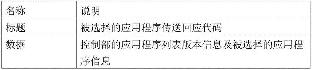

Referring to Table 4, the response text may also include a header, data, and error correction elements. The header may include code indicating that the response text includes length information and that the current response text is a response to the request for the application information selected by the security element 220.
The data part may include version information of the application list of the control part 210 and information on the application selected by the selection part 230. The security element 220 receiving the response text determines whether the versions of the application list are consistent or not, and then activates the selected application to perform the payment operation.
Finally, the control unit 210 inserts an error correction element into the full response text, so that the security element 220 receiving the full response text determines whether the currently received data is reliable or not.
As described above, the secure element 220 receives information on the selected payment method from the control section 210, determines the main payment method based on the information thus received, and activates the selected application program to perform the payment operation. In this process, the information exposed between the secure element 220 and the control section 210 may be the kind and version information of the application program provided to the secure element 220. Since other information is not exposed, the electronic card 20 of the present invention can selectively activate and use a plurality of applications stored in the security element 220 while utilizing the stability of the security element 220.
According to an embodiment, after a specific application is activated in the security element 220, the activated application information is provided to the control part 210. The control part 210 displays information related to the activated application program to the user through the display part 260 so that the user can confirm in which payment method the current payment is implemented.
According to an embodiment, the control part 210 may display error information through the display part 260 in a case where an application program in the secure element 220 is not normally activated, or an application program based on a payment method set by the control part 210 is not stored in the secure element 220 and cannot be operated by the payment method set by the control part 210, or version information of the application program of the secure element 220 is different from the application program version information of the control part 210 and an error occurs.
According to the payment method activation information, the application program related to the payment method is activated in the security element 220, and accordingly, the electronic card 20 may receive the payment approval result in case of normally implementing the payment. The payment approval result may be received through the security element 220 or the control part 210, and may be displayed through the display part 260.
FIG. 3 is a block diagram of an electronic card illustrating an embodiment of the present invention.
In contrast to the electronic card 20 of fig. 2, the electronic card 20 'of fig. 3 may also include a charging circuit 255 connecting the security element 220 with the power supply 250'. The same components as those of fig. 2 are denoted by the same reference numerals, have substantially the same structures, perform substantially the same operations, and thus detailed descriptions thereof are omitted.
In the electronic card 20 of fig. 2, after the power supply 250 formed inside the electronic card 20 is consumed, the payment method setting of the control unit 210 cannot be realized unless the power is supplied from the outside. However, the electronic card 20' of fig. 3 has a chargeable power supply 250', receives power through the contact portion 225 contacting with the outside, and charges the power supply 250' through the charging circuit 255.
Accordingly, the battery of the electronic card 20 'can be fully discharged, and the power supply 250' can be charged, so as to prolong the service life of the electronic card.
With reference to fig. 4 to 8, a plurality of embodiments of the selection unit included in the electronic card will be described. The selection unit 230 can be presented in various forms in view of the appearance of the electronic card. The following description is made with reference to the form of the selection unit as viewed in appearance, and the internal function of the selection unit is realized in relation to the form of the appearance of the selection unit.
A plurality of elements constituting the selection unit in fig. 4 to 8 are referred to as selection elements. As mentioned above, the plurality of selection elements comprises mechanical or electrical selection means.
Referring to fig. 4, a plurality of selection elements may be arranged in rows and columns. In fig. 4 and 5a to 5c, a plurality of selection elements are illustrated as being arranged in a 3 × 3 matrix form, and the description is based on this, but the present invention is not limited thereto, and various modifications can be made as required. Further, although the selection elements of the selection unit 130a may be presented as objects that are physically divided, they may be divided by a boundary (i.e., logical division) divided based on a field (e.g., coordinates) of an electrical division in a single field.
When the user sequentially inputs the selection elements and inputs the pattern for the plurality of selection elements constituting the selection unit 130a included in the electronic card 10a of fig. 4, the control unit 210 recognizes the input pattern and sets the payment method matching the pattern.
Fig. 5a to 5c exemplarily illustrate patterns input through a plurality of selection elements possessed by the electronic card of fig. 4.
Fig. 5a to 5c show that the plurality of card selection buttons 230 formed on the electronic card 20, 20' include nine buttons having a matrix form of 3X 3. For convenience of explanation, a row (row) and a column (column) of a plurality of card selection buttons are expressed in (x, y) coordinates, and a specific card selection button is indicated. The upper left button is designated as the (1, 1) button.
Referring to fig. 5a, the (1, 1) button, the (2, 3) button, and the (3, 1) button are sequentially input. Such a time-ordered combination of multiple buttons, represented by a dashed line, may be recognized as indicating the letter 'V'. Accordingly, the user recognizes that 'V' is input in the plurality of card selection buttons 230 to input a pattern. Such a payment means related to a pattern related to the user's cognition may be managed as "VISA". The payment method related to the predefined pattern may be managed by the storage means of the control section 210 as described above. Also, various changes may be made to the payment method associated with the predefined pattern or the application associated with the payment method.
Referring to fig. 5b, the (1, 3), (1, 2), (1, 1), (2, 2), (3, 1), (3, 2), and (3, 3) buttons are sequentially input to form a pattern in the shape of a letter 'M'. As described above, the control unit 210 recognizes the time-series combination of the plurality of card selection buttons as the predefined pattern of 'M', determines the payment method corresponding thereto, internally determines that the payment method is the set payment method, and displays it on the display unit 260. For example, 'M' may be managed as a "mastercard" payment means.
Referring to fig. 5c, the buttons (1, 3), (1, 2), (1, 1), (2, 1), (3, 2), (3, 3) and (2, 2) are sequentially input to form a pattern in the shape of a letter 'a'. Similarly, the control unit 210 recognizes this as 'a', and thus regards it as corresponding to a predefined pattern, and generates the payment method activation information from the "AMEX" payment method corresponding to the pattern.
However, as described above, the first three inputs of the plurality of card selection buttons in fig. 5b and 5c are the same. In this case, it is difficult to confirm which pattern is input inside. Accordingly, at least one button present in the present invention as included in the buttons of the plurality of card selection buttons indicates that the pattern input is completed, thereby helping the control part 210 to recognize the predefined pattern.
In another embodiment, the length of the pattern to be input may be set to be the same. For example, fig. 5a shows a pattern formed by three button inputs, fig. 5b shows a seven button input, and fig. 5c shows a pattern formed by eight button inputs. As described, when the lengths of the patterns are different, the operation efficiency of the control part 210 may be reduced, and thus the length of the predefined pattern may be set to a fixed length. For example, the control unit 210 needs to continuously calculate a predetermined time and determine whether or not the input of the plurality of selection elements forms a predetermined pattern, but needs to wait until the input having the longest pattern length is received to determine the input of the pattern if the lengths of the patterns are different from each other. However, if there is a reference that the predefined pattern is all completed by four button inputs, etc., it is determined that the predefined pattern is not input by four button inputs, and the sleep mode may be immediately entered or the pattern input may be initialized.
In fig. 5a to 5c, it is exemplarily illustrated that the predefined pattern is composed of a first letter called a letter of a payment method, but not limited thereto, and a plurality of predefined patterns are formed based on a combination of a plurality of card selection buttons recognizable by a user, and may be changed according to a user setting after first issuing a card. The control part 210 determines whether the inputted card selection button corresponds to a predefined pattern, and sets the information of the payment method as the main payment card of the electronic card 20, 20' if the inputted card selection button corresponds to the predefined pattern. Meanwhile, the control part 210 may display information of the set payment method through the display part 260.
Table 5 exemplarily shows a relationship between a predefined pattern and a payment method managed by the control section 210.
[ Table 5]
| Indexing | Inputting patterns | Payment mode | Whether or not to select | Displaying information |
| 1 | V | VISA | Visa/Visa | |
| 2 | K | KONA-money | O | KONA-money/Kona wallet |
| 3 | A | AMEX | AMEX/fortune | |
| 4 | M | Mastercard | Mastercard/Mastercard | |
| 5 | C | CUP | CUP | |
| 6 | J | JCB | JCB | |
| ... | ... | ... | ... | ... |
When a certain input pattern is input in relation to information of an application program provided to the security element 220, the control part 210 may determine whether a specific payment method is selected. Also, the information of the input pattern may include information of all the buttons input in time series.
According to the embodiment, the control unit 210 communicates with the security element 220 to recognize the kind of the application program stored in the security element 220, and can activate recognition of the input pattern matching with the corresponding application program. For example, the control part 210 may store input pattern information on all applications that may be provided to the secure element 220, but the applications provided to the secure element 220 may be different therefrom. Therefore, the control unit 210 recognizes only the pattern related to the application provided to the safety element 220, and when the pattern related to the application not provided to the safety element 220 is input, the pattern is not recognized or determined as an erroneous input, and feedback is provided through the display unit 260.
The control part 210 judges that a predefined pattern is input and records as selecting a corresponding payment method. The control unit 210 deletes information on a pattern related to an application not provided in the security element 220, and secures a memory space inside the control unit 210.
According to an embodiment, the control part 210 may store information related to a currently selected payment method. As shown in table 5, when the electronic card 20, 20' in the sleep state is activated by the input of the activation control part 240 when the payment method of the kona wallet is selected, information that ' the kona wallet ' is set is displayed through the display part 260.
If the user holds down the activation control part 240 in order to set 'coanda wallet' as the payment method, but finds that 'coanda wallet' has been set as the payment method, an input signal may be provided to the activation control part 240 to shift the control part 210 to the sleep state or the control part 210 may be shifted to the sleep state without any input for a preset time, without an additional pattern input.
According to the embodiment, the control part 210 manages information displayed in the display part 260 when a predefined pattern is input. Table 5 shows that the name of the payment method is displayed on the display unit 260, but according to the embodiment, any information may be used as long as the information can identify the type of the payment method. According to an embodiment, the security element 220 may have a plurality of cards of the same card brand as a payment method, and the combined information of the card brand and the card number/CVC number, etc. is displayed on the display portion 260.
According to the embodiment, information displayed in the display part 260 may be edited outside the card to be provided to the control part 210 through the security element 220.
When the security element 220 makes a request, the control unit 210 may transmit a reply full text corresponding to the payment method activation information based on the management information as shown in table 5. For example, the control part 210 may generate and transmit a response full text as described with reference to table 4 to the secure element 220.
Fig. 6 shows a selection portion of an electronic card according to another embodiment of the present invention.
Referring to fig. 6, the selection part 130b is composed of a plurality of selection elements, and may be composed of ten selection elements so that one digit of all the decimal numbers may be input. As described above, the numbers from 0 to 9 may be input through ten selection elements or other values corresponding to the respective selection elements may be input in sequence. The number of selection elements shown in fig. 6 is exemplary, and a plurality of numbers of selection elements may be included in the selection part 130b according to an embodiment.
According to the embodiment, each selection element of the selection part 130b is matched with each payment method, respectively, and the payment method can be set by selecting the selection element of the selection part 130b once. In another embodiment, more than ten payment methods may be matched, and the user may input a number to set the payment method matched with the corresponding number. For example, when ten or more payment methods are stored in the security element 220, if the number of selection elements is limited, ten or more payment methods cannot be recognized and input. Accordingly, the user continuously inputs a selection element indicating "1" and a selection element indicating "5", waits for a preset time, or in another embodiment, a selection element corresponding to "confirm" is input and a signal for setting a corresponding fifteenth payment method is input.
Fig. 7 shows a selection portion of an electronic card according to another embodiment of the present invention.
Referring to fig. 7, the selection part 130c may include a plurality of selection elements to select left and right. The user can confirm the types of the applications displayed on the left and right selection element confirmation display portions 160, select the left and right, and after confirming the payment method, which is the application, and display the payment method required on the display portion 260, the user can hold the selection for a certain period of time or can press the left and right selection elements at the same time to complete the selection.
Referring to fig. 8, the selection part 130d may include a plurality of selection elements that select upper and lower. Selecting the upper and lower selection elements sequentially confirms the plurality of payment methods displayed on the display unit 160 in a similar manner to the selection unit 130c of fig. 7, but as another interface method, a slide input method may be adopted.
For example, if the left and right selection elements of the selection unit 130c of fig. 7 adopt a button input method in which selection is released by one selection, the up and down selection elements of the selection unit 130d of fig. 8 may be operated in a slide input method. That is, if the up-down selection element does not react to the pressure and the up selection element 131 is selected via the down selection element 133, it is recognized as moving up, and if the down selection element 133 is selected via the selection element 131, it is recognized as moving down and the operation is performed. Therefore, the upper and lower selection elements 131 and 133 correspond to selection elements that react only to a touch.
As described above, the electronic caine card main body according to the embodiments of the present invention has the selection portion that can be realized by the plurality of selection elements and can select the application program related to the payment method in a plurality of ways. Accordingly, user convenience can be improved, and the plurality of selection elements can be used for another purpose in the payment process.
FIG. 9 is a flow chart for explaining an operation method of the electronic card according to an embodiment of the present invention.
The method of operating the electronic card of the present invention may comprise the steps of: an initialization step (steps S910 to S913) of sharing information of the application recorded in the secure element 220 with the control section 210; a step (step S920) of receiving the selection signal by the selection unit 230 and selecting a program related to the payment method; and a step in which the secure element 220 receives information set as a payment method from the control section 210 when payment is made (steps S930 to S932).
These three steps may be performed in series or individually, and although illustrated as described above in fig. 9, are not limited to being performed in this order.
Referring to fig. 9, in the initialization step, an application is recorded in the secure element 220 (step S910). The application recorded to the secure element 220 may be transferred to the secure element 220 through an external card-issuing terminal. The contents of the application recorded in the security element 220 may be the same as the information described with reference to table 1. The secure element 220 transfers the application list to the control section 210 (step S911).
The control section 210 stores the application list received from the secure element 220 in association with the selection section. That is, when receiving a signal of a certain type from the selection unit 230, the control unit 210 may select and store an application program of a received application program list in a matching manner.
The control part 210 transmits a response to the reception of the application list to the secure element 220 (step S930). The full response transmitted by the control unit 210 may have the same data format as that described in table 2. The control part 210 informs the secure element 220 of the confirmed version information of the application list, and the secure element 220 may transmit the application list again when the version information of the application list transmitted by the secure element 220 is different from the version information of the application list of the control part 210.
According to the embodiment, the control part 210 transmits a response to the recording of the application list to the secure element 220 after storing the application list, and then stores the stored application list in association with the selection part.
Steps S910 to S913 may be performed in an initial step of recording the application in the secure element 220, that is, in a credit card issuance step, and according to the embodiment, when the power of the control part 210 is cut off as the power of the electronic card is completely exhausted, the application information recorded in the control part 210 is completely disappeared, and the application list of the control part 210 is initialized, regardless of the card issuance.
According to an embodiment, in addition to the card company recording application, information about which selection part 230 the control part 210 will select a specific payment method when inputting, may be transmitted to the control part 210 via the secure element 220 by an external device. For example, the application list information transmitted from the security element 220 to the control section 210 may include index information of the application, information displayed on the display section when the application is selected, and the like.
As described with reference to fig. 4 and 5a to 5c, when a specific application is selected by a predefined pattern, an input pattern may be determined and stored in the security element 220 together with the application when the card company issues a card, or a user may edit the predefined pattern as necessary and provide it to the control unit 210 through the security element 220.
Also, the user matches the payment means, which is mainly used by the user, to the selection element, which is convenient for input, according to the order of priority among the plurality of applications stored in the security element 220. For example, when the application program related to the payment method is matched to each selection element included in the selection unit 230, the user edits the application program matched to the selection unit 230 and provides the edited application program to the security element 220 in order to match the payment method mainly used by the user to the first and second selection elements, and the security element 220 transmits the edited application program list to the control unit 210, thereby changing the application program matched to the selection unit 230.
Such editing can be done by index (index) editing of tables 6 to 7. In table 6, indices are formed in the order of VISA, KONA-money, AMEX, Mastercard, CUP, and JCB, and the indices are matched with the selection unit according to the order of the indices.
[ Table 6]
| Indexing | Payment mode (application program) |
| 1 | |
| 2 | KONA- |
| 3 | |
| 4 | |
| 5 | |
| 6 | JCB |
| ... | ... |
However, the index information may be modified as in table 7, and the secure element 220 transfers it to the control section 210 in an application list. In this case, the control unit 210 matches the selection elements of the selection unit 230 in the order of the indices of KONA-money, JCB, Mastercard, AMEX, CUP, and VISA, and thus when the same selection element of the selection unit 230 is input, if VISA was previously selected, KONA-money in table 7 is selected after modification, and KONA-money was previously selected before modification of the indices, JCB is selected after modification.
[ Table 7]
| Indexing | Payment mode (application program) |
| 1 | KONA- |
| 2 | |
| 3 | |
| 4 | |
| 5 | |
| 6 | VISA |
| ... | ... |
In another embodiment, the application list information may include payment method indication information that allows the display unit 260 to confirm which payment method is currently selected, such as a left-right selection element (see fig. 7) or a top-bottom selection element (see fig. 8), when the application is selected.
[ Table 8]


According to an embodiment, the display information is edited and the edited display information is transmitted to the control part 210 through the security element 220. For example, as in table 8, the display information for identifying the payment means may be constituted by the name of the payment means, the letter and four-digit card number representing the payment means, the CVC number, or the like. As described above, such display information indicates an example, and various modifications can be implemented as necessary.
According to the embodiment, the above-described steps S910 to S913 are repeatedly performed each time the application list information stored in the secure element 220 is updated.
The application list is transmitted to the control unit 210, and the main payment method is selected by the selection unit 230 (step S920). Selection of an application related to the payment method will be specifically described with reference to fig. 10 and 11.
When the selection unit 230 selects the payment method, the control unit 210 generates and internally manages the payment method activation information, and transmits the payment method activation information in response to the application information selected by the security element 220 (step S930) (step S931). When payment is requested, the request signal transmitted from the secure element 220 to the control unit 210 is equivalent to the command full text described with reference to table 3, and in response to this, the control unit 210 transmits the selected application information (step S932). The response transmitted from the control unit 210 to the security element 220 may have the same data format as the full response described with reference to table 4.
According to an embodiment, when the user does not select the application related to the payment method, i.e., in a state where step S920 is not performed, the security element 220 may request the selected application information from the control part 210. In this case, the control unit 210 may transmit information that the selected value does not exist, or information that the payment method designated as the top-priority index is selected as described with reference to fig. 6 to 8.
As described with reference to fig. 9, the electronic card according to the present invention communicates between the security element 220 requiring security and the control unit 210 to transfer information of an application program, and controls activation of the application program selected by the user. Further, by transmitting and receiving a plurality of kinds of information related to the application program, it is possible to perform various changes to a method selectable according to user's convenience, and also to change a mode displayed on the display unit. Accordingly, the electronic card has the advantage of improving the convenience of users for the electronic card.
Fig. 10 and 11 are flowcharts for explaining an operation method of the electronic card according to the embodiment of the present invention, and particularly, a method of selecting an application program related to a payment method.
Referring to fig. 10, the activation control unit 240 formed in the plate-shaped electronic card receives an input signal (step S921). As the activation control 240 receives an input, the power supply 250, 250' supplies power to the control 210.
The control unit 210 switches from the sleep state to the active state in response to the input from the active control unit 240, and starts to calculate the preset time (step S922). Due to the transition to the activated state, the control part 210 may display information identifying the currently set payment method through the display part 260. According to an embodiment, the display part 260 obtains power required for operation from the power source 250, 250'.
The control part 210 calculates a preset time and waits for an input of the selection part 230. For example, the control section 210 may recognize that at least one of a plurality of selection elements constituting the selection section 230 is input. When an input is received from the selection part within a preset time (yes at step S923), the control part 210 generates payment means activation information based on the input of the selection part 230 (step S925). As described above, the selection part 230 can be implemented in various ways, and the control part 210 can recognize the input of the selection part 230 in various ways. According to an embodiment, the control part 210 displays payment means information through the display part 260 in real time in response to the input of the selection part.
When an input is received from the selection unit 230 within the preset time, the control unit 210 initializes the preset time (step S924) and recalculates the preset time. When a new input is received from the selection unit, the input is recognized by the new selection regardless of the previous selection, or when the input from the selection unit is recognized sequentially, the input from the selection unit is received sequentially and recognized.
According to the embodiment, the payment means activation information formed in the control part 210 is provided in case that the security element 220 is activated to be activated by a specific application program within the security element 220, and then, information for identifying the activated payment means is displayed through the display part 260.
When the selection unit 230 receives no input (no at step S923), and the activation control unit 240 receives an input (yes at step S926), the control unit 210 enters the sleep mode (step S928). For example, if the user originally wants to set the payment method through the activation control unit 240 and confirms that the currently set payment method is the payment method required by the user through the display unit 260, the user does not perform another payment method setting and enters the sleep mode by inputting the new payment method again through the activation control unit 240.
If the activation button is not input (no at step S926), the control section 210 determines whether or not the preset time has elapsed (step S927). If the preset time is exceeded (yes at step S927), the control unit 210 enters the sleep mode (step S928), and if the preset time is not exceeded (no at step S927), it waits for an input from the selection unit 230.
Fig. 11 is a flowchart for explaining an operation method of an electronic card when a selection associated in chronological order is input to the selection portion.
Compared to the method for operating the electronic card described with reference to fig. 10, the method for operating the electronic card shown in fig. 11 is the same except that the steps of determining whether the input forms a predetermined pattern according to the input of the selection part, recognizing the pattern, and generating the payment means activation information are different.
Receiving an input from the selection unit 230 (yes at step S923), the control unit 210 determines whether the input of the selection element forms a predefined pattern (step S9251).
The control unit 210 sequentially determines the input of the selection elements and determines in real time whether or not the input pattern matches an internally managed input pattern.
When the input of the selection element does not form a pattern (no at step S9251), the activation control section 240 is input again (yes at step S926), and the control section 210 enters the sleep mode (step S926). According to the embodiment, when the pattern is not formed by the input of the selection part 230 (no at step S9251), the control part 210 displays information of a pattern input error or a payment method setting error through the display part 260.
When the input of the selection section does not form a pattern (no at step S9251), and the activation control section 240 also does not receive an input (no at step S926), the control section 210 determines whether the calculated time exceeds the preset time. If the preset time is not exceeded (no at step S927), the control unit 210 waits for the input of the selection unit 230 until the preset time is exceeded. If the preset time is exceeded (yes at step S927), the control unit 210 may enter the sleep mode (S928).
The above-described operation method is an operation method of an electronic card set to be activated for one of a plurality of application programs of the security element 220 provided to the electronic card 20, 20'. The payment means set in the above-described method operates such that the application program related to the payment means, which is transmitted as the payment means activation information through the activation of the security element 220, is activated.
As described above, the plurality of card selection buttons formed on one electronic card 20, 20 'of the plate shape are input by the time-series combination of the button inputs to set a specific payment method, and the electronic card 20, 20' can realize a plurality of payment methods.
The present invention has been described in detail centering on the preferred embodiments shown in the drawings as described above. The foregoing embodiments are merely exemplary and are not to be construed as limiting the present invention, which should be construed in a non-limiting sense from the standpoint of illustration. The true technical scope of the present invention should be determined based on the technical idea of the claims, not the above description. Although specific terms are used in the present description, they are used only for explaining the concept of the present invention, and do not limit the scope of the present invention described in the claims. The steps of the present invention are not necessarily performed in the order described, and may be performed in parallel, selectively, or individually. Those skilled in the art to which the present invention pertains will appreciate that other embodiments can be modified in various forms and equivalents thereof without departing from the essential technical idea of the present invention claimed in the claims. The equivalents include not only currently known equivalents but also equivalents to be developed in the future, i.e., all means which perform the same function regardless of structure.
Claims (19)
1. An electronic card, comprising:
a plate-shaped chucking plate;
the safety element is embedded into the plate-shaped card board and stores a plurality of application programs related to payment modes;
a control part for identifying one of the plurality of application programs and generating payment mode activation information based on the selection signal received by the selection part formed on the card board; and
a display part displaying information identifying a payment means based on the payment means activation information,
wherein the control part manages an application identified based on the selection signal as a selected application as being stored in association with the selection signal along with a plurality of application information provided based on the security element, thereby generating the payment means activation information,
in case of an external payment attempt, the secure element receives the payment means activation information from the control part to activate the selected application.
2. The electronic card of claim 1, further comprising:
and a power supply formed on the card board, activated independently of card payment, and supplying power to the control unit and the selection unit to drive transmission and reception of the selection signal.
3. The electronic card of claim 2,
the plurality of application information provided by the security element to the control part includes at least one of an index of each of the applications, information displayed on the display part to identify each of the applications, and a payment means description associated with each of the applications.
4. The electronic card of claim 2,
the secure element requests the payment means activation information to the control part in response to an external payment request.
5. The electronic card of claim 4,
in response to a change in the plurality of pieces of application information, the secure element transmits the changed application information to the control unit.
6. The electronic card of claim 2,
the control unit displays information identifying a payment method set based on the payment method activation information on the display unit as the power supply starts supplying power.
7. The electronic card of claim 2,
the control unit displays information identifying payment methods associated with the plurality of applications on the display unit in response to a selection signal of the selection unit.
8. The electronic card of claim 7,
the selection part includes at least one of upper, lower, left, and right selection elements for sequentially selecting the plurality of applications.
9. The electronic card of claim 2,
and if the power supply starts to supply power within a preset time, the control part enters a sleep mode if the selection part does not input power.
10. The electronic card of claim 9,
the card board is provided with a power supply control part, and the card board is provided with a power supply control part.
11. The electronic card of claim 10,
and if the input of activating the control part is received within the preset time from the power supply starting point, the control part enters the sleep mode.
12. The electronic card of claim 3,
the control unit matches the index information in the application information with the selection signal.
13. An electronic card operating method using an electronic card including a security element embedded in a plate-shaped card board, comprising the steps of:
the security element transmits information of the set plurality of applications to the control part; and
the secure element requesting information of an application selected from the plurality of applications to the control part in response to an external payment request;
the security element activates a respective application based on the selected application information.
14. The method of operation of an electronic card of claim 13, further comprising:
the control unit manages by matching a plurality of application information received from the security element with a selection signal received by a selection unit formed in the card.
15. The method of operation of an electronic card of claim 14, further comprising:
the control unit identifies one selected application program from the plurality of application programs based on the selection signal and generates payment method activation information.
16. The method of operation of an electronic card of claim 14, further comprising:
the secure element receiving a response based on the transmission of the plurality of application information from the control section; and
the security element retransmits the plurality of pieces of application information based on application version information included in the response of the control section.
17. The method of operation of an electronic card of claim 14, further comprising:
a power supply formed on the plate-shaped card board supplies power to the control part and the selection part in response to the input of the activation control part;
the control part responds to the input of the activation control part to start to calculate the preset time; and
the control part enters a sleep mode in the preset time without an input of the selection part or receiving an input of the activation control part.
18. The method of operation of an electronic card of claim 17, further comprising:
the control part initializes calculation of the preset time when the input of the selection part is received within the preset time.
19. The method of operation of an electronic card of claim 14, further comprising:
the control unit displays information identifying a payment method associated with the selected application program through a display unit formed on the card.
Applications Claiming Priority (3)
| Application Number | Priority Date | Filing Date | Title |
|---|---|---|---|
| KR10-2017-0091524 | 2017-07-19 | ||
| KR1020170091524A KR101971431B1 (en) | 2017-07-19 | 2017-07-19 | Electronic Card and Method of operating Electronic Card |
| PCT/KR2018/008164 WO2019017705A1 (en) | 2017-07-19 | 2018-07-19 | Electronic card and method for operating electronic card |
Publications (1)
| Publication Number | Publication Date |
|---|---|
| CN111033546A true CN111033546A (en) | 2020-04-17 |
Family
ID=65015874
Family Applications (1)
| Application Number | Title | Priority Date | Filing Date |
|---|---|---|---|
| CN201880055094.9A Withdrawn CN111033546A (en) | 2017-07-19 | 2018-07-19 | Electronic card and electronic card operation method |
Country Status (6)
| Country | Link |
|---|---|
| US (1) | US11100491B2 (en) |
| EP (1) | EP3657418A4 (en) |
| JP (1) | JP6907402B2 (en) |
| KR (1) | KR101971431B1 (en) |
| CN (1) | CN111033546A (en) |
| WO (1) | WO2019017705A1 (en) |
Families Citing this family (2)
| Publication number | Priority date | Publication date | Assignee | Title |
|---|---|---|---|---|
| KR102536948B1 (en) | 2018-10-29 | 2023-05-25 | 삼성전자주식회사 | Method and apparatus for managing bundles of smart secure platform |
| CN115167952B (en) * | 2022-08-25 | 2023-01-20 | 深圳市汇顶科技股份有限公司 | Security element, application program management method, electronic device and storage medium |
Citations (6)
| Publication number | Priority date | Publication date | Assignee | Title |
|---|---|---|---|---|
| KR20110062620A (en) * | 2009-12-03 | 2011-06-10 | 유비벨록스(주) | Financial alliance service providing system using electronic wallet device and financial alliance service providing method using same |
| KR20160008945A (en) * | 2014-07-14 | 2016-01-25 | 브릴리언츠 주식회사 | Method for payment and saving by smart multi card and appilcation for smart multi card |
| KR20160090633A (en) * | 2015-01-22 | 2016-08-01 | 삼성전기주식회사 | Smart card and a fingerprint recognition system using thereof |
| CN106056386A (en) * | 2016-07-25 | 2016-10-26 | 重庆馥莉信息科技有限公司 | Payment method, payment terminal, server and payment system |
| CN106255984A (en) * | 2014-05-29 | 2016-12-21 | 苹果公司 | For operating portable electric appts to move the apparatus and method of payment transaction |
| CN106357600A (en) * | 2015-07-14 | 2017-01-25 | 三星电子株式会社 | Card registration method for payment service and mobile electronic device implementing the method |
Family Cites Families (11)
| Publication number | Priority date | Publication date | Assignee | Title |
|---|---|---|---|---|
| US20060196929A1 (en) * | 2005-03-02 | 2006-09-07 | International Business Machines Corporation | Multiple use secure transaction card |
| US9324071B2 (en) * | 2008-03-20 | 2016-04-26 | Visa U.S.A. Inc. | Powering financial transaction token with onboard power source |
| US8201747B2 (en) * | 2008-11-26 | 2012-06-19 | Qsecure, Inc. | Auto-sequencing financial payment display card |
| US20100250812A1 (en) * | 2009-02-26 | 2010-09-30 | Richard Webb | Electronic multipurpose card |
| US9053398B1 (en) * | 2010-08-12 | 2015-06-09 | Dynamics Inc. | Passive detection mechanisms for magnetic cards and devices |
| US20130228616A1 (en) * | 2012-03-02 | 2013-09-05 | Amazon Technologies, Inc. | Dynamic Payment Card |
| US20160148194A1 (en) * | 2013-03-14 | 2016-05-26 | Nagraid Security, Inc. | Radio Frequency Powered Smart, Debit and Credit Card System Employing a Light Sensor to Enable Authorized Transactions |
| WO2014145673A1 (en) | 2013-03-15 | 2014-09-18 | Mastercard International Incorporated | Methods and apparatus for providing and operating an enhanced payment display card with network support |
| US9275386B2 (en) * | 2013-05-29 | 2016-03-01 | Stratos Technologies, Inc. | Method for facilitating payment with a programmable payment card |
| KR101598371B1 (en) * | 2014-07-14 | 2016-02-29 | 브릴리언츠 주식회사 | Smart multi card |
| US9230255B1 (en) * | 2014-08-15 | 2016-01-05 | Mastercard International Incorporated | Payment card having light-emitting diode indicators coordinated with stored payment applications |
-
2017
- 2017-07-19 KR KR1020170091524A patent/KR101971431B1/en not_active Expired - Fee Related
-
2018
- 2018-07-19 CN CN201880055094.9A patent/CN111033546A/en not_active Withdrawn
- 2018-07-19 JP JP2020502335A patent/JP6907402B2/en not_active Expired - Fee Related
- 2018-07-19 US US16/631,369 patent/US11100491B2/en not_active Expired - Fee Related
- 2018-07-19 EP EP18835885.7A patent/EP3657418A4/en not_active Withdrawn
- 2018-07-19 WO PCT/KR2018/008164 patent/WO2019017705A1/en not_active Ceased
Patent Citations (6)
| Publication number | Priority date | Publication date | Assignee | Title |
|---|---|---|---|---|
| KR20110062620A (en) * | 2009-12-03 | 2011-06-10 | 유비벨록스(주) | Financial alliance service providing system using electronic wallet device and financial alliance service providing method using same |
| CN106255984A (en) * | 2014-05-29 | 2016-12-21 | 苹果公司 | For operating portable electric appts to move the apparatus and method of payment transaction |
| KR20160008945A (en) * | 2014-07-14 | 2016-01-25 | 브릴리언츠 주식회사 | Method for payment and saving by smart multi card and appilcation for smart multi card |
| KR20160090633A (en) * | 2015-01-22 | 2016-08-01 | 삼성전기주식회사 | Smart card and a fingerprint recognition system using thereof |
| CN106357600A (en) * | 2015-07-14 | 2017-01-25 | 三星电子株式会社 | Card registration method for payment service and mobile electronic device implementing the method |
| CN106056386A (en) * | 2016-07-25 | 2016-10-26 | 重庆馥莉信息科技有限公司 | Payment method, payment terminal, server and payment system |
Also Published As
| Publication number | Publication date |
|---|---|
| WO2019017705A1 (en) | 2019-01-24 |
| US11100491B2 (en) | 2021-08-24 |
| US20200219084A1 (en) | 2020-07-09 |
| JP6907402B2 (en) | 2021-07-21 |
| JP2020530146A (en) | 2020-10-15 |
| KR20190009576A (en) | 2019-01-29 |
| EP3657418A1 (en) | 2020-05-27 |
| KR101971431B1 (en) | 2019-04-23 |
| EP3657418A4 (en) | 2021-04-28 |
Similar Documents
| Publication | Publication Date | Title |
|---|---|---|
| US10783514B2 (en) | Method and apparatus for use in personalizing identification token | |
| US20180144163A1 (en) | Antenna decoupled from programmable smart card | |
| CN111033546A (en) | Electronic card and electronic card operation method | |
| US20100240318A1 (en) | Mobile electronic device and control method of mobile electronic device | |
| KR101773376B1 (en) | Smart card and control method thereof and charging apparatus therefor and smart card reader | |
| CN107534462A (en) | Charging Electronics Using an NFC Front End | |
| CN109313761B (en) | Selecting applications on a card | |
| CN105512716A (en) | Multifunctional IC card | |
| EP3968293A1 (en) | Multi-card including fingerprint input unit and payment method using the same | |
| EP2717193B1 (en) | IC card, portable electronic device, and reader/ writer | |
| US10282729B2 (en) | Methods, apparatus and media for use in association with identification token and/or in docking | |
| EP2711872B1 (en) | IC Card, Portable electronic device, and reader/ writer | |
| KR20190041993A (en) | Electronic Card and Method of operating Electronic Card | |
| US20220350975A1 (en) | Ic card, ic card processing system, and computer-readable storage medium | |
| JP6009854B2 (en) | IC card, portable electronic device, and IC card control program | |
| JP2005275456A (en) | Portable electronic medium, integrated circuit used for portable electronic medium, and method for issuing portable electronic medium | |
| JP2023139488A (en) | IC cards, portable electronic devices and IC card processing systems | |
| KR101760669B1 (en) | Smart card sequentially generating dynamic magnetic field and control method thereof | |
| WO2017028405A1 (en) | Smart card and payment terminal integrated device and control method thereof | |
| TW202221601A (en) | Mobile payment device and operation method thereof wherein the mobile payment device includes central control unit, an identity authentication module, an input interface, a display module, a security chip, an induction antenna and a quadrilateral casing | |
| TWM607786U (en) | Mobile payment device | |
| JP2012068728A (en) | Card adapter device | |
| KR20180114879A (en) | Card | |
| EP3086272A1 (en) | Selecting an application on a card | |
| KR20170120551A (en) | Card |
Legal Events
| Date | Code | Title | Description |
|---|---|---|---|
| PB01 | Publication | ||
| PB01 | Publication | ||
| SE01 | Entry into force of request for substantive examination | ||
| SE01 | Entry into force of request for substantive examination | ||
| WW01 | Invention patent application withdrawn after publication | ||
| WW01 | Invention patent application withdrawn after publication |
Application publication date: 20200417 |