CN110998032A - Excavator - Google Patents
Excavator Download PDFInfo
- Publication number
- CN110998032A CN110998032A CN201880050344.XA CN201880050344A CN110998032A CN 110998032 A CN110998032 A CN 110998032A CN 201880050344 A CN201880050344 A CN 201880050344A CN 110998032 A CN110998032 A CN 110998032A
- Authority
- CN
- China
- Prior art keywords
- shovel
- lower traveling
- predetermined
- information
- control device
- Prior art date
- Legal status (The legal status is an assumption and is not a legal conclusion. Google has not performed a legal analysis and makes no representation as to the accuracy of the status listed.)
- Pending
Links
Images


Classifications
-
- E—FIXED CONSTRUCTIONS
- E02—HYDRAULIC ENGINEERING; FOUNDATIONS; SOIL SHIFTING
- E02F—DREDGING; SOIL-SHIFTING
- E02F9/00—Component parts of dredgers or soil-shifting machines, not restricted to one of the kinds covered by groups E02F3/00 - E02F7/00
- E02F9/26—Indicating devices
- E02F9/261—Surveying the work-site to be treated
- E02F9/262—Surveying the work-site to be treated with follow-up actions to control the work tool, e.g. controller
-
- E—FIXED CONSTRUCTIONS
- E02—HYDRAULIC ENGINEERING; FOUNDATIONS; SOIL SHIFTING
- E02F—DREDGING; SOIL-SHIFTING
- E02F3/00—Dredgers; Soil-shifting machines
- E02F3/04—Dredgers; Soil-shifting machines mechanically-driven
- E02F3/64—Buckets cars, i.e. having scraper bowls
- E02F3/65—Component parts, e.g. drives, control devices
- E02F3/651—Hydraulic or pneumatic drives; Electric or electro-mechanical control devices
-
- E—FIXED CONSTRUCTIONS
- E02—HYDRAULIC ENGINEERING; FOUNDATIONS; SOIL SHIFTING
- E02F—DREDGING; SOIL-SHIFTING
- E02F9/00—Component parts of dredgers or soil-shifting machines, not restricted to one of the kinds covered by groups E02F3/00 - E02F7/00
- E02F9/20—Drives; Control devices
- E02F9/2025—Particular purposes of control systems not otherwise provided for
- E02F9/2033—Limiting the movement of frames or implements, e.g. to avoid collision between implements and the cabin
-
- E—FIXED CONSTRUCTIONS
- E02—HYDRAULIC ENGINEERING; FOUNDATIONS; SOIL SHIFTING
- E02F—DREDGING; SOIL-SHIFTING
- E02F9/00—Component parts of dredgers or soil-shifting machines, not restricted to one of the kinds covered by groups E02F3/00 - E02F7/00
- E02F9/20—Drives; Control devices
- E02F9/2025—Particular purposes of control systems not otherwise provided for
- E02F9/2041—Automatic repositioning of implements, i.e. memorising determined positions of the implement
-
- E—FIXED CONSTRUCTIONS
- E02—HYDRAULIC ENGINEERING; FOUNDATIONS; SOIL SHIFTING
- E02F—DREDGING; SOIL-SHIFTING
- E02F9/00—Component parts of dredgers or soil-shifting machines, not restricted to one of the kinds covered by groups E02F3/00 - E02F7/00
- E02F9/24—Safety devices, e.g. for preventing overload
-
- E—FIXED CONSTRUCTIONS
- E02—HYDRAULIC ENGINEERING; FOUNDATIONS; SOIL SHIFTING
- E02F—DREDGING; SOIL-SHIFTING
- E02F9/00—Component parts of dredgers or soil-shifting machines, not restricted to one of the kinds covered by groups E02F3/00 - E02F7/00
- E02F9/26—Indicating devices
- E02F9/264—Sensors and their calibration for indicating the position of the work tool
- E02F9/265—Sensors and their calibration for indicating the position of the work tool with follow-up actions (e.g. control signals sent to actuate the work tool)
Landscapes
- Engineering & Computer Science (AREA)
- Mining & Mineral Resources (AREA)
- Civil Engineering (AREA)
- General Engineering & Computer Science (AREA)
- Structural Engineering (AREA)
- Mechanical Engineering (AREA)
- Operation Control Of Excavators (AREA)
- Component Parts Of Construction Machinery (AREA)
Abstract
An excavator according to an embodiment of the present invention includes: a lower traveling body (1); an upper revolving body (3) which is mounted on the lower traveling body (1) and is provided with an attachment; and a controller (30) mounted on the upper slewing body (3). The controller (30) restricts the operation of the lower traveling body (1) on the basis of information relating to changes in the topography surrounding the upper slewing body (3). The controller (30) restricts the operation of the lower traveling body (1) on the basis of information on the terrain caused by, for example, excavation work.
Description
Technical Field
The present disclosure relates to a shovel having a lower traveling body.
Background
Conventionally, a shovel having a measuring device for measuring a topography around an upper revolving body from a stereopair image captured by a camera attached to the upper revolving body is known (see patent document 1). Through this structure, measuring device can generate and show the topography data of job site in real time.
Prior art documents
Patent document
Patent document 1: international publication No. 2017/033991
Disclosure of Invention
Technical problem to be solved by the invention
However, when an operator of the excavator repeats the traveling operation, the turning operation, and the attachment operation in order to perform the excavation work, the operator may forget the orientation of the lower traveling body. Further, the lower traveling body may be moved in a direction opposite to the desired direction.
In this case, the measuring device generates and displays the topographic data only from the stereopair image, and therefore, even when a pit exists in the moving direction of the excavator, the excavator cannot be stopped from moving. As a result, the body of the excavator may be unstable.
In view of the above, it is desirable to provide a shovel capable of preventing a machine body from becoming unstable.
Means for solving the technical problem
An excavator according to an embodiment of the present invention includes: a lower traveling body; an upper revolving body mounted on the lower traveling body and provided with an attachment; and a control device mounted on the upper slewing body, the control device restricting an operation of the lower traveling body based on information on a topography around the upper slewing body.
Effects of the invention
By the above means, a shovel capable of preventing the body from becoming unstable can be provided.
Drawings
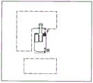
Fig. 1 is a side view of an excavator according to an embodiment of the present invention.
Fig. 2 is a side view of a shovel showing a configuration example of the attitude detection device mounted on the shovel of fig. 1.
Fig. 3 is a diagram showing a configuration example of a basic system mounted on the shovel of fig. 1.
Fig. 4 is a diagram showing a configuration example of a hydraulic system mounted on the shovel of fig. 1.
Fig. 5 is a diagram showing a configuration example of an external computing device.
Fig. 6 is a diagram showing another configuration example of the external computing device.
Fig. 7 is a flowchart of the walking restriction process.
Fig. 8A is a sectional view of the ground of the work object.
Fig. 8B is a sectional view of the work object floor.
Fig. 8C is a sectional view of the ground of the work object.
Fig. 9A is a top view of a job site.
Fig. 9B is a top view of the job site.
Fig. 9C is a top view of the job site.
Detailed Description
First, a shovel (excavator) as a construction machine according to an embodiment of the present invention will be described with reference to fig. 1. Fig. 1 is a side view of an excavator according to an embodiment of the present invention. An upper revolving body 3 is mounted on a lower traveling body 1 of the excavator via a revolving mechanism 2. A boom 4 is attached to the upper slewing body 3. An arm 5 is attached to a tip of the boom 4, and a bucket 6 is attached to a tip of the arm 5. The boom 4, the arm 5, and the bucket 6 as the work elements constitute an excavation attachment as an example of an attachment. The boom 4 is driven by a boom cylinder 7. The arm 5 is driven by an arm cylinder 8. The bucket 6 is driven by a bucket cylinder 9. The upper slewing body 3 is provided with a cab 10 and a power source such as an engine 11. Further, the upper slewing body 3 is mounted with a communication device M1, a positioning device M2, and an attitude detecting device M3.
The communication device M1 is configured to control communication between the shovel and the outside. In the present embodiment, the communication device M1 controls wireless communication between a GNSS (Global Navigation Satellite System) measurement System and the shovel. Specifically, the communication device M1 acquires the topographic information on the work site at the time of starting the operation of the shovel, for example, at a frequency of once a day. The GNSS measurement system employs, for example, a network-type RTK-GNSS positioning method.
The positioning device M2 is configured to measure the position of the shovel. The positioning device M2 may be configured to measure the orientation of the shovel. In the present embodiment, the positioning device M2 is a GNSS receiver incorporating an electronic compass, and is attached to the upper slewing body 3. Then, the latitude, longitude, and altitude of the existing position of the shovel are measured, and the orientation of the shovel (upper revolving unit 3) is measured. The positioning device M2 may include a turning angle detection device that detects the turning angle of the upper turning body 3 with respect to the lower traveling body 1. With this configuration, the positioning device M2 can measure the orientation of the lower traveling structure 1 from the orientation of the shovel (upper revolving structure 3). However, the orientation of the lower traveling body 1 may be measured by another GNSS receiver.
The posture detecting device M3 is configured to detect the posture of the accessory device. The posture detection device M3 can acquire, for example, a motion trajectory of the attachment according to the operation. In the present embodiment, the attitude detecting means M3 detects the attitude of the excavation attachment.
Fig. 2 is a side view of the shovel showing a configuration example of various sensors included in the attitude detection device M3 mounted on the shovel of fig. 1. Specifically, the attitude detection device M3 includes a boom angle sensor M3a, an arm angle sensor M3b, a bucket angle sensor M3c, and a vehicle body inclination sensor M3 d.
The boom angle sensor M3a is configured to acquire a boom angle θ 1. The boom angle θ 1 is, for example, an angle of a line segment connecting the boom foot pin position P1 and the arm link pin position P2 on the XZ plane with respect to the horizontal line.
The arm angle sensor M3b is configured to acquire an arm angle θ 2. The arm angle θ 2 is, for example, an angle of a line segment connecting the arm link pin position P2 and the bucket link pin position P3 on the XZ plane with respect to the horizontal line.
The bucket angle sensor M3c is configured to acquire a bucket angle θ 3. The bucket angle θ 3 is, for example, an angle of a line segment connecting the bucket connecting pin position P3 and the bucket cutting edge position P4 on the XZ plane with respect to the horizontal line.
In the present embodiment, the boom angle sensor M3a is configured by a combination of an acceleration sensor and a gyro sensor. However, the boom cylinder may be configured by a rotation angle sensor that detects a rotation angle of the boom foot pin, a stroke sensor that detects a stroke amount of the boom cylinder 7, an inclination sensor that detects an inclination angle of the boom 4, or the like. The same applies to the arm angle sensor M3b and the bucket angle sensor M3 c.
The vehicle body inclination sensor M3d is configured to acquire an inclination angle θ 4 of the shovel about the Y axis and an inclination angle θ 5 of the shovel about the X axis (not shown). The vehicle body inclination sensor M3d includes, for example, a biaxial inclination (acceleration) sensor, a triaxial inclination (acceleration) sensor, or the like. The XY plane of fig. 2 is a horizontal plane.
Next, a basic system of the shovel will be described with reference to fig. 3. Fig. 3 is a diagram showing a configuration example of a basic system of the excavator, and a mechanical power transmission line, a hydraulic oil line, and a pilot line are indicated by a double line, a solid line, and a broken line, respectively. The basic system of the excavator mainly includes an engine 11, a main pump 14, a pilot pump 15, a control valve 17, an operation device 26, a controller 30, an Engine Control Unit (ECU)74, and the like.
The engine 11 is a drive source of the shovel, and is, for example, a diesel engine that operates to maintain a predetermined rotational speed. The output shaft of the engine 11 is connected to the input shafts of the main pump 14 and the pilot pump 15, respectively.
The main pump 14 is a hydraulic pump, for example, a swash plate type variable displacement hydraulic pump, which supplies hydraulic oil to a control valve 17 through a hydraulic oil line 16. The main pump 14 can change the discharge rate, i.e., the pump output, by adjusting the stroke length of the pistons by changing the angle of the swash plate (swash plate tilt angle). The swash plate tilt angle of the main pump 14 is controlled by a regulator 14 a. The regulator 14a changes the swash plate tilt angle according to a change in control current received by an attached solenoid valve (not shown). For example, when the control current increases, the regulator 14a increases the swash plate tilt angle to increase the discharge rate of the main pump 14. When the control current decreases, the regulator 14a decreases the swash plate tilt angle to decrease the discharge rate of the main pump 14.
The pilot pump 15 is a hydraulic pump for supplying hydraulic oil to various hydraulic control devices via a pilot line 25, and is, for example, a fixed displacement hydraulic pump.
The control valve 17 is a set of hydraulic control valves that control a hydraulic system mounted on the shovel. In this embodiment, a plurality of flow control valves are included. The control valve 17 selectively supplies, for example, working oil supplied from the main pump 14 through the working oil line 16 to one or more hydraulic actuators according to the operation direction and the operation amount of the operation device 26. The hydraulic actuators include, for example, a boom cylinder 7, an arm cylinder 8, a bucket cylinder 9, a left traveling hydraulic motor 1A, a right traveling hydraulic motor 1B, and a turning hydraulic motor 2A. The left traveling hydraulic motor 1A, the right traveling hydraulic motor 1B, and the turning hydraulic motor 2A may be formed of electric motors.
The operating device 26 is a device for operating the hydraulic actuator by an operator, and includes a joystick, a pedal, or the like. In the present embodiment, the operation device 26 receives a supply of hydraulic oil from the pilot pump 15 via the pilot line 25. Then, the working oil is supplied to the pilot port of the flow control valve corresponding to each hydraulic actuator through the pilot lines 25a and 25 b. The pressure of the hydraulic oil supplied to the pilot port becomes a pressure corresponding to the operation direction and the operation amount of the operation device 26 corresponding to each hydraulic actuator.
The controller 30 is a control device for controlling the shovel, and is constituted by a computer having a CPU, a RAM, a ROM, and the like, for example. The controller 30 executes programs corresponding to the various functions to realize the various functions. The various functions include a function of controlling the discharge amount of the main pump 14 by changing the magnitude of the control current to the solenoid valve of the regulator 14 a.
The Engine Control Unit (ECU)74 is configured to control the engine 11. The ECU74 controls the rotation speed of the engine 11, for example, in accordance with an instruction from the controller 30. The operator sets the engine speed using, for example, the engine speed adjustment dial 75. The ECU74 controls the fuel injection amount and the like to achieve the set engine speed.
The engine speed adjustment dial 75 is a dial for adjusting the speed of the engine 11, and is provided in the cab 10. In the present embodiment, the engine speed can be switched in 5 stages. The operator can switch the engine speed in 5 stages of Rmax, R4, R3, R2, and R1 by operating the engine speed adjustment dial 75. Fig. 3 shows a state in which R4 is selected by the engine speed adjustment dial 75.
The image display device 40 is a device for displaying various kinds of information, and is provided in the cab 10. In the present embodiment, the image display device 40 includes an image display unit 41 and an input unit 42. The operator can check the operation state of the excavator, control information, and the like by observing the image display unit 41. The operator can input various information to the controller 30 by using the input unit 42. The image display device 40 is connected to the controller 30 via a communication network such as CAN or LIN. However, the image display device 40 may be connected to the controller 30 via a dedicated line.
The image display device 40 includes a conversion processing unit 40a that generates an image for display. In the present embodiment, the conversion processing section 40a generates a camera image for display from the output of the imaging device M5 as a device for acquiring the surface state of the feature. The imaging device M5 is, for example, a monocular camera connected to the image display device 40 via a dedicated line. The imaging device M5 may be a stereo camera, a range image camera (range image sensor), an infrared camera, an infrared thermal imaging camera, or the like. The conversion processing section 40a may generate an image for display from the output of the controller 30.
The conversion processing section 40a can be realized not only as a function of the image display device 40 but also as a function of the controller 30. In this case, the image pickup device M5 is connected to the controller 30, not to the image display device 40.
The image display device 40 operates by receiving power supply from the battery 70. The battery 70 is charged with electric power generated by an alternator 11a (generator) of the engine 11. The electric power of the battery 70 is supplied to the controller 30, the image display device 40, the electrical components 72 of the excavator, and the like. The starter 11b is driven by electric power from the battery 70 to start the engine 11.
The ECU74 sends various data indicating the state of the engine 11 to the controller 30. The various data include, for example, data indicating the cooling water temperature output by the water temperature sensor 11c, data indicating the swash plate tilt angle of the main pump 14 output by the regulator 14a, data indicating the discharge pressure of the main pump 14 output by the discharge pressure sensor 14b, data indicating the temperature of the hydraulic oil output by the oil temperature sensor 14c, data indicating the pilot pressure output by the operating pressure sensors 29a and 29b, and data indicating the setting state of the engine speed output by the engine speed adjustment dial 75. The controller 30 stores the data in the temporary storage section 30a and can transmit it to the image display apparatus 40 when necessary.
The external computing device 30E is a control device that performs various computations based on the output of at least one of the communication device M1, the positioning device M2, the posture detection device M3, the imaging device M5, and the like, and outputs the computation results to the controller 30. In the present embodiment, the external computing device 30E operates by receiving power supply from the battery 70.
Fig. 4 is a diagram showing a configuration example of a hydraulic system mounted on the shovel. The hydraulic system mainly includes main pumps 14L and 14R, a pilot pump 15, a control valve 17, an operation device 26, a switching valve 50, and the like. Main pumps 14L, 14R correspond to main pump 14 of fig. 3.
The control valve 17 includes flow control valves 171 to 176 that control the flow of the hydraulic oil discharged from the main pumps 14L and 14R. The control valve 17 selectively supplies the hydraulic oil discharged from the main pumps 14L and 14R to one or more of the boom cylinder 7, the arm cylinder 8, the bucket cylinder 9, the left traveling hydraulic motor 1A, the right traveling hydraulic motor 1B, and the turning hydraulic motor 2A via the flow rate control valves 171 to 176.
The operation content detection device 29 is configured to detect the operation content of the operation device 26 by the operator. In the present embodiment, the operation content detection means 29 is constituted by operation pressure sensors 29a, 29b that detect the operation direction and the operation amount of the operation device 26 corresponding to each hydraulic actuator in the form of pressure. The operation content detection device 29 may be configured by a sensor other than the pressure sensor, such as a potentiometer.
The main pumps 14L, 14R driven by the engine 11 circulate the hydraulic oil to the hydraulic oil tank through the intermediate bypass lines 40L, 40R, respectively. The intermediate bypass line 40L is a hydraulic oil line passing through flow control valves 171, 173, and 175 disposed in the control valve 17. The intermediate bypass line 40R is a hydraulic oil line passing through flow control valves 172, 174, and 176 disposed in the control valve 17.
The flow control valves 171, 172, and 173 are spool valves that control the flow rate and the flow direction of the hydraulic oil flowing into the left traveling hydraulic motor 1A, the right traveling hydraulic motor 1B, and the turning hydraulic motor 2A. The flow control valves 174, 175, and 176 are spool valves that control the flow rate and the flow direction of the hydraulic oil flowing into the bucket cylinder 9, the arm cylinder 8, and the boom cylinder 7.
The left traveling hydraulic motor 1A and the right traveling hydraulic motor 1B are traveling hydraulic motors that drive the lower traveling body 1. In the present embodiment, the swash plate type variable displacement hydraulic motor is configured to be capable of switching the travel mode between a high speed travel mode in which high rotation and low torque are applied and a low speed travel mode in which low rotation and high torque are applied. The traveling mode is switched by a motor governor attached to the traveling hydraulic motor. The motor regulator can switch the traveling mode of the traveling hydraulic motor in accordance with at least one of a command from the controller 30, a traveling load (pressure of hydraulic oil flowing through the traveling hydraulic motor), and the like. In the high-speed travel mode, the swash plate deflection angle is small, and the displacement (motor volume) per rotation of the hydraulic motor is small. In the low-speed walking mode, the inclined plate deflection angle is large, and the motor volume is large.
The switching valve 50 is a valve that switches between communication and cutoff between the operation device 26 and the pilot ports of the flow control valves 171 to 176. In the present embodiment, the switching valve 50 is an electromagnetic valve that switches the valve position according to a control command from the controller 30. Specifically, the switching valve 50 partially or completely blocks the communication between the operation device 26 and each pilot port when receiving a blocking instruction from the controller 30, and releases the blocking between the operation device 26 and each pilot port when receiving a communication instruction. The switching valve 50 may be a proportional solenoid valve capable of controlling the flow rate.
Next, the function of the external computing device 30E will be described with reference to fig. 5. Fig. 5 is a functional block diagram showing a configuration example of the external computing device 30E. In the present embodiment, the external arithmetic device 30E receives the outputs of the communication device M1, the positioning device M2, and the posture detection device M3, performs various arithmetic operations, and outputs the arithmetic results thereof to the controller 30. The controller 30 outputs a control command corresponding to the calculation result to the operation limiting unit E1, for example.
The operation restriction unit E1 is a functional element for restricting the operation of the shovel, and includes, for example, a pressure reducing valve for adjusting the pilot pressure, a switching valve capable of shutting off the flow of hydraulic oil from the main pump 14 to the control valve 17, and the like. In the present embodiment, the switching valve 50 is adopted as the operation restricting portion E1. The operation restricting portion E1 may include a warning output device that outputs a warning to an operator of the shovel. The warning output device is, for example, a sound output device or a warning lamp.
The external computing device 30E mainly includes a terrain database updating unit 31, a position coordinate updating unit 32, a terrain shape information acquiring unit 33, and a travel limiting unit 34.
The topography database update unit 31 is a functional element for updating a topography database in which topographic information on a work site is systematically stored so as to be referred to. In the present embodiment, the topography database update unit 31 acquires the topography information of the work site via the communication device M1 and updates the topography database, for example, when the excavator is started. The topography database is stored in a non-volatile memory or the like. For example, topographic information of a work site is described in a three-dimensional topographic model based on a world positioning system.
The position coordinate updating unit 32 is a functional element for updating the coordinates and the orientation indicating the current position of the shovel. In the present embodiment, the position coordinate updating unit 32 acquires the position coordinates and orientation of the shovel in the world positioning system based on the output of the positioning device M2, and updates data on the coordinates and orientation indicating the current position of the shovel stored in a nonvolatile memory or the like. The position coordinate updating unit 32 may acquire the position coordinates and the orientation of the shovel from a navigation estimation (Dead reckong) using an output of a gyro sensor, an acceleration sensor, or the like.
The floor surface shape information acquisition unit 33 is a functional element for acquiring information on the current shape of the floor surface of the work object. In the present embodiment, the ground shape information acquiring unit 33 acquires information on the current shape of the work target ground surface based on the terrain information updated by the terrain database updating unit 31, the coordinates and the direction indicating the current position of the shovel updated by the position coordinate updating unit 32, and the past change (work history) in the posture of the excavation attachment detected by the posture detecting device M3. Therefore, ground shape information acquisition unit 33 can acquire information on a change in the terrain surrounding upper slewing body 3 including information on a change in the terrain due to excavation work. The work history, which is a past change in the posture of the excavation attachment, is time-series data of at least one of a boom angle θ 1, an arm angle θ 2, a bucket angle θ 3, a tilt angle θ 4 of the excavator about the Y axis, a tilt angle θ 5 of the excavator about the X axis, and the like, and is stored in the volatile memory or the nonvolatile memory. The floor surface shape information acquiring unit 33 may delete the work history up to now after acquiring the information on the current shape of the work target floor surface. The ground shape information acquiring unit 33 may acquire information on the current shape of the work target ground surface from the coordinates and the direction indicating the current position of the shovel updated by the position coordinate updating unit 32 and the past change (work history) in the posture of the excavation attachment detected by the posture detecting device M3.
The travel limiting section 34 is a functional element for limiting travel of the shovel. In the present embodiment, the travel restricting unit 34 restricts the operation of the lower traveling member 1 based on the coordinates and the direction indicating the current position of the shovel updated by the position coordinate updating unit 32 and the information on the current shape of the work target ground acquired by the ground shape information acquiring unit 33. For example, the travel restricting unit 34 restricts the forward movement of the lower traveling body 1 when it is determined that the predetermined ground object is present within a predetermined distance in the forward direction of the lower traveling body 1, and restricts the backward movement of the lower traveling body 1 when it is determined that the predetermined ground object is present within a predetermined distance in the backward direction of the lower traveling body 1. The predetermined ground object is, for example, a ground object satisfying a predetermined condition among ground objects such as a pit and mound formed by excavation work. In the present embodiment, the predetermined ground object includes a pit deeper than a predetermined depth, a pit having a side surface (inclined surface) with an inclination angle larger than a predetermined angle, mound higher than a predetermined height, mound having a side surface (inclined surface) with an inclination angle larger than a predetermined angle, and the like. If the lower traveling body 1 passes over a predetermined ground object, the posture of the excavator becomes significantly unstable. The forward direction and the backward direction of the lower traveling body 1 are determined based on the output of the positioning device M2, for example.
For example, the travel restricting section 34 defines a pit formed by excavation as a predetermined feature, the pit having a side surface inclined at an angle equal to or greater than a predetermined angle, and excludes a pit having an inclination angle smaller than the predetermined angle from the predetermined feature. Alternatively, among the pits formed by the excavation work, pits having a depth equal to or greater than a predetermined depth may be used as the predetermined feature, and pits having a depth less than the predetermined depth may be excluded from the predetermined feature. Similarly, the travel restricting section 34 uses, as the predetermined ground feature, a mound whose side surface inclination angle is equal to or greater than a predetermined angle among mounds formed by excavation work, for example, and excludes a mound whose inclination angle is smaller than the predetermined angle from the predetermined ground feature. Alternatively, a mound having a height equal to or higher than a predetermined height among mounds formed by excavation work may be used as the predetermined ground object, and a mound having a height lower than the predetermined height may be excluded from the predetermined ground object.
The limitation of the travel of the excavator includes at least one of limitation of the maximum moving speed of the lower traveling body 1, limitation of the maximum moving acceleration, limitation of the maximum moving distance, prohibition of movement, and the like. In the present embodiment, when it is determined that a predetermined feature is present within a predetermined distance in the forward direction of the lower traveling unit 1, the traveling restriction unit 34 outputs the determination result to the controller 30. The controller 30 having received the determination result outputs a shutoff command to the switching valve 50 as the operation restriction unit E1. The switching valve 50 that receives the cutoff command cuts off communication between the travel operation device as the operation device 26 and the right pilot ports of the flow control valve 171 and the flow control valve 172, respectively, to prohibit the excavator from advancing. The walking operation device comprises a walking rod and a walking pedal. The maximum forward speed may be limited by lowering the upper limit of the pilot pressure acting on the right pilot port of each of the flow control valves 171 and 172. Alternatively, the excavator may be stopped when the distance to the predetermined ground object becomes smaller than a predetermined value.
The controller 30 may limit the moving speed of the lower traveling body 1 by outputting a command to a motor regulator serving as the operation limiting unit E1 and fixing the traveling mode of the hydraulic motor for traveling to the low-speed traveling mode.
In the present embodiment, the lower traveling body 1 includes a left crawler belt and a right crawler belt. The controller 30 may restrict the operation of the left crawler belt and the right crawler belt at the same time, or may restrict the operation of the left crawler belt and the right crawler belt individually.
With this configuration, the controller 30 can prevent the excavator from being caught in a pit as a predetermined ground object or standing on mound as a predetermined ground object due to an erroneous operation by an operator. The erroneous operation by the operator includes a backward operation to advance the lower traveling body 1 and an forward operation to retreat the lower traveling body 1.
Next, another configuration example of the external computing device 30E will be described with reference to fig. 6. The external computing device 30E of fig. 6 is different from the external computing device 30E of fig. 5 in that the ground shape information acquisition unit 33 can acquire information on the current shape of the work target ground surface from the output of the image pickup device M5, but is common to other points. Therefore, the description of the common portions is omitted, and the different portions are described in detail.
The imaging device M5 may be attached to the excavation attachment or may be attached to the cab 10. This is to enable imaging of the surrounding terrain by rotating together with the rotation of the upper rotating body 3. However, the imaging device M5 may be attached to a pole (pole) or the like installed at a work site, or may be attached to a flight vehicle flying around the excavator. The flying object includes, for example, a multi-axis helicopter (multicopter) or an airship.
In the example of fig. 6, the ground shape information acquiring unit 33 can acquire information on the current shape of the work target ground from the distance image output from the imaging device M5, such as a stereo camera or a distance image camera, for example. When the imaging device M5 is attached to the excavation attachment, the distance image is converted into a distance image with the positioning device M2 (excavator) as a reference, based on the relative positional relationship between the positioning device M2 and the imaging device M5. When the imaging device M5 is attached to the column, the distance image is converted into a distance image based on the positioning device M2 (excavator) based on the attachment position (latitude, longitude, and height) of the imaging device M5 measured in advance. When the imaging device M5 is attached to the flying object, the distance image is converted into a distance image based on the positioning device M2 (shovel) based on the output of the positioning device M2 and the output of the positioning device M5 mounted on the flying object.
The ground shape information acquiring unit 33 may acquire information on the current shape of the ground of the work object based on an output of a distance measuring device such as a radar or a laser distance meter as a device for acquiring the surface state of the ground object. In this case, as in the case of the imaging device M5, the distance measuring device may be attached to an excavation attachment, may be attached to a column or the like installed at a work site, or may be attached to a flying object flying around the excavator. The distance information measured by the distance measuring device is converted into distance information based on the excavator in the same manner as described above.
As described above, the camera M5 may be independent from the shovel. In this case, the controller 30 may acquire the topographic information output by the image pickup device M5 via the communication device M1. Specifically, the imaging device M5 may be mounted on a multi-axis helicopter for aerial photography, a pylon installed at a work site, or the like, and acquires topographic information on the work site from an image of the work site viewed from above. The imaging device M5 may be an imaging device M5 provided in another excavator. When the imaging device M5 is independent from the shovel, the imaging device M5 may transmit data directly to the shovel or may transmit data to the shovel via the management device. The management device is, for example, a computer installed in an external facility such as a management center. In this way, when the imaging device M5 is independent of the shovel, the geographic map database update unit 31 acquires the geographic map information from the external imaging device M5 or the geographic map information from the management device via the communication device M1. The topography database update unit 31 can update the topography information around the shovel based on the acquired topography information, and the ground shape information acquisition unit 33 can acquire information on a change in the topography based on the topography information updated by the topography database update unit 31.
With this configuration, the controller 30 can more reliably prevent the excavator from being caught in a pit as the predetermined ground object or standing on the mound as the predetermined ground object due to an erroneous operation by the operator.
Next, a process of limiting the operation of the lower traveling body 1 by the controller 30 (hereinafter referred to as "traveling limiting process") will be described with reference to fig. 7 and 8A to 8C. Fig. 7 is a flowchart of the walking restriction process. The controller 30 repeatedly executes the travel restricting process at a predetermined control cycle. The ground shape information acquisition unit 33 of the controller 30 acquires information on the current shape of the work target ground in parallel with the travel restriction process. Typically, the ground shape information acquiring unit 33 periodically acquires information on the current shape of the work target ground surface based on the terrain information updated by the terrain database updating unit 31, the coordinates and the direction indicating the current position of the shovel updated by the position coordinate updating unit 32, and the past change (work history) in the posture of the excavation attachment detected by the posture detecting device M3. Fig. 8A to 8C are cross-sectional views of the work target floor, and show the case where the shape changes in the order of fig. 8A, 8B, and 8C. The one-dot chain line in each of fig. 8A to 8C indicates a target topography (a topography achieved by excavation work). The excavator acquires data relating to the target terrain via the communication device M1.
First, the travel restricting unit 34 of the controller 30 determines whether or not a predetermined feature exists within a predetermined distance in the forward direction (step ST 1). In this example, the predetermined ground includes a pit deeper than the predetermined depth TH1 and having a side surface inclination angle larger than the predetermined angle TH2, and a mound higher than the predetermined height TH3 and having a side surface inclination angle larger than the predetermined angle TH 4.
The travel restricting unit 34 determines whether or not the predetermined feature is present within a predetermined distance in the forward direction, for example, by grasping the shape of the predetermined feature and the distance to the predetermined feature. The predetermined distance in the advancing direction is, for example, a horizontal distance from the front end of the lower traveling body 1.
When it is determined that the predetermined feature is present within the predetermined distance in the forward direction (yes at step ST1), the travel limiting unit 34 limits the forward movement (step ST 2).
When it is determined that the predetermined feature is not present within the predetermined distance in the forward direction (no in step ST1), the travel restricting unit 34 determines whether or not the predetermined feature is present within the predetermined distance in the backward direction (step ST 3).
When it is determined that the predetermined feature is present within the predetermined distance in the backward direction (yes at step ST3), the travel restricting unit 34 restricts backward movement (step ST 4). The predetermined distance in the retreating direction is, for example, a horizontal distance from the rear end of the lower traveling body 1.
When it is determined that the predetermined feature is not present within the predetermined distance in the backward direction (no in step ST3), that is, when it is determined that the predetermined feature is not present in both the forward direction and the backward direction, the travel restricting unit 34 restricts neither the forward movement nor the backward movement, and ends the travel restricting process of this time.
In the example of fig. 7, the travel restricting unit 34 determines whether or not the predetermined feature is present within the predetermined distance in the backward direction after determining that the predetermined feature is not present within the predetermined distance in the forward direction. However, the travel restricting unit 34 may determine whether or not the predetermined feature is present within the predetermined distance in the forward direction after determining that the predetermined feature is not present within the predetermined distance in the backward direction. Alternatively, both decisions may be performed in parallel at the same time.
For example, in the state of fig. 8A, only a pit having a depth D1 smaller than the predetermined depth TH1 exists within the predetermined distance F in the forward direction, and therefore the travel restriction unit 34 determines that there is no predetermined feature in the forward direction, and this pit has a side surface having an inclination angle α 1 larger than the predetermined angle TH2, but is not determined as a predetermined feature because the depth D1 is smaller than the predetermined depth TH1, and therefore, the travel restriction unit 34 does not need to restrict the forward travel, but a pit having a depth D1 may be determined as a predetermined feature because it has a side surface having an inclination angle α 1 larger than the predetermined angle TH2, and in this case, the travel restriction unit 34 restricts the forward travel.
Further, the travel restricting unit 34 determines that the predetermined ground object is not present in the backward direction because only the mound of the height H1 smaller than the predetermined height TH3 is present within the predetermined distance R in the backward direction, the mound having the side surface with the inclination angle β 1 larger than the predetermined angle TH4, but the height H1 smaller than the predetermined height TH3 is not determined as the predetermined ground object, and therefore, the travel restricting unit 34 does not restrict the backward movement, but the mound of the height H1 may be determined as the predetermined ground object because the side surface having the inclination angle β 1 larger than the predetermined height TH4, in which case the travel restricting unit 34 restricts the backward movement.
In the state of fig. 8B, the pit extending to the depth D2 of the predetermined depth TH1 or more exists within the predetermined distance F in the forward direction, but the inclination angle α 2 of the side surface thereof is smaller than the predetermined angle TH2, so the travel restricting section 34 determines that the predetermined feature does not exist in the forward direction, and the mound extending to the height H2 of the predetermined height TH3 or more exists within the predetermined distance R in the backward direction, but the inclination angle β 2 of the side surface thereof is smaller than the predetermined angle TH4, so the travel restricting section 34 determines that the predetermined feature does not exist in the backward direction.
In the state of fig. 8C, since the predetermined distance F in the forward direction includes the pit having the depth D3 extending to the predetermined depth TH1 or more and the inclination angle α 3 of the side surface thereof is the predetermined angle TH2 or more, the travel restricting unit 34 restricts forward movement, and since the predetermined distance R in the backward direction includes the mound having the height H3 extending to the predetermined height TH3 or more and the inclination angle β 3 of the side surface thereof is the predetermined angle TH4 or more, the travel restricting unit 34 determines that the predetermined feature exists in the backward direction, the travel restricting unit 34 restricts backward movement.
The ground shape information acquisition unit 33 may set, as the limit range, a range of the distance L from the edge of the pit determined as the predetermined ground feature to the depth D3 of the pit, and may limit the operation of the lower traveling body 1 so that the excavator does not enter the limit range. In this case, the ground shape information acquiring unit 33 can suppress the excavator from approaching the predetermined feature by setting the range of the predetermined distance from the predetermined feature as the limit range, and can further improve safety.
Next, a change in the position of the predetermined feature with the progress of the excavation work will be described with reference to fig. 9A to 9C. Fig. 9A to 9C are plan views of a work site, and show a case where excavation work is performed in the order of fig. 9A, 9B, and 9C. The one-dot chain line in each of fig. 9A to 9C indicates the position of a pit constituting the target topography. The dot pattern indicates the position of a pit as a predetermined land object. The diagonal line pattern indicates the position of the mound as a predetermined ground object.
Fig. 9A shows a state of a work site before excavation work is performed. The one-dot chain line indicates that pits are intended to be formed at two places. In the state of fig. 9A, since there is no predetermined ground object, the travel restricting portion 34 does not restrict the travel of the shovel.
Fig. 9B shows a state of the work site when the excavator is excavating the 1 st pit out of the two pits. The dot pattern indicates that pits as predetermined land are formed in a range corresponding to the 1 st pit. The diagonal line pattern indicates that mounds as predetermined ground objects are formed of earth and sand excavated to form the 1 st pit. In the state of fig. 9B, the travel restricting portion 34 restricts the forward movement of the shovel. This is because a pit as a predetermined ground object exists within a predetermined distance F in the forward direction of lower traveling unit 1. On the other hand, the travel restricting portion 34 does not restrict the backward movement of the shovel. This is because there is no predetermined ground object within the predetermined distance R in the backward direction of the lower traveling body 1.
Fig. 9C shows a state of the work site when the excavator excavates the 2 nd pit after formation of the 1 st pit of the two pits is completed. The dot pattern indicates that pits as predetermined land are formed in a range corresponding to pit 1 and a range corresponding to pit 2. The diagonal line pattern indicates that mounds as predetermined ground objects are formed of earth and sand dug out to form the 1 st and 2 nd pits. In the state of fig. 9C, the travel restricting portion 34 restricts the backward movement of the shovel. This is because there is a pit (2 nd pit) as a predetermined feature within a predetermined distance R in the backward direction of lower traveling body 1. On the other hand, the travel restricting portion 34 does not restrict the forward movement of the shovel. This is because there is no predetermined ground object within the predetermined distance F in the forward direction of the lower traveling body 1.
As described above, when a predetermined ground object is present within a predetermined distance in the moving direction, the controller 30 restricts the operation of the lower traveling body 1. Therefore, it is possible to prevent the excavator from falling into a pit excavated by the excavator or from standing on a mound formed by the excavator. This restriction is particularly effective in a situation where the operator moves the lower propelling body 1 in the direction opposite to the intended direction. Such a situation occurs, for example, when the operator is concentrating too much on the operation of the attachment and erroneously regards the forward direction of the lower traveling body 1 as the backward direction. However, it is also effective when the operator moves the lower propelling body 1 in a desired direction. This is because it is difficult for the operator to find the presence of a predetermined ground object such as a pit or mound from the cab 10 or to forget the presence of the predetermined ground object.
As described above, the excavation mechanism according to the embodiment of the present invention is configured such that the controller 30 restricts the operation of the lower traveling structure 1 based on the information on the peripheral topography of the upper revolving structure 3. Typically, the excavation mechanism is configured such that the controller 30 restricts the operation of the lower traveling structure 1 based on information on a change in the topography around the upper slewing body 3. Therefore, the shovel according to the embodiment of the present invention can prevent the shovel from being in an unstable state due to, for example, being stuck in a pit dug by the shovel or standing on a mound formed by the shovel or another shovel.
The controller 30 preferably restricts the operation of the lower traveling unit 1 based on information on a change in the terrain caused by the excavation work. In particular, the operation of the lower traveling structure 1 is restricted based on information on a change in the terrain due to the excavation work of the machine. Therefore, the excavator with the controller 30 mounted thereon can prevent the excavator from being in an unstable state due to being stuck in a pit dug by the excavator or standing on mound formed by the excavator.
The controller 30 preferably acquires information on a change in the terrain due to the excavation work from the operation history of the attachment including the detection value of the posture detection device M3. Therefore, the shovel equipped with the controller 30 can reliably and accurately acquire information on a pit dug by the shovel itself, information on mound formed by the shovel itself, and the like.
The controller 30 may acquire information on changes in the terrain around the upper revolving structure 3 based on the output of a device (e.g., the imaging device M5 or the distance measuring device) for acquiring the surface state of the feature or a device (e.g., the attitude detecting device M3) for acquiring the movement locus of the attachment. Therefore, the shovel equipped with the controller 30 can reliably and accurately acquire information on a pit excavated by the shovel itself or another shovel, information on a mound formed by the shovel itself or another shovel, and the like over a wide range of work sites.
A device (for example, the imaging device M5 or the distance measuring device) for acquiring the surface state of the ground object or a device (for example, the posture detecting device M3) for acquiring the movement locus of the attachment is preferably attached to the attachment. Therefore, the device (for example, the imaging device M5 or the distance measuring device) for acquiring the surface state of the feature or the device (for example, the attitude detecting device M3) for acquiring the movement locus of the attachment changes the imaging direction, the measuring direction, or the excavation position according to the rotation of the upper revolving structure 3, and therefore the surrounding terrain can be imaged, measured, or derived over a wide range.
The lower traveling body 1 is typically driven by a hydraulic motor of a variable displacement type. In this case, the controller 30 can restrict the operation of the lower traveling body 1 by fixing the traveling mode of the hydraulic motor to the low-speed traveling mode, that is, by preventing the switching to the high-speed traveling mode. Therefore, the controller 30 can easily and quickly restrict the operation of the lower traveling unit 1.
The controller 30 preferably restricts at least one of the moving direction and the moving speed of the lower traveling unit 1. Therefore, the controller 30 can prevent the lower traveling body 1 from entering the predetermined ground object without restricting the movement of the lower traveling body 1 in the direction away from the predetermined ground object.
The controller 30 may set a range of a predetermined distance from a predetermined ground object as the limit range. With this configuration, the controller 30 can more reliably suppress the excavator from approaching the predetermined ground, and can further improve safety.
The controller 30 may be configured to acquire information on the topography around the upper slewing body 3 from an imaging device M5 outside the shovel. With this structure, the controller 30 can more easily acquire topographic information of the work site.
The preferred embodiments of the present invention have been described above. However, the present invention is not limited to the above-described embodiments. The above-described embodiment can be applied to various modifications, replacements, and the like without departing from the scope of the present invention. Further, as long as there is no technical contradiction, each feature described with reference to the above embodiments may be appropriately combined.
For example, in the above-described embodiment, the external arithmetic device 30E has been described as another arithmetic device located outside the controller 30, but may be integrated with the controller 30. The external computing device 30E may not be mounted on the shovel. For example, the external computing device 30E may be installed in an external management facility such as a management center. In this case, the external computing device 30E may receive data acquired by at least one of the positioning device M2, the attitude detection device M3, the imaging device M5, and the like via the network, and calculate information on the terrain, such as construction completion information. Also, the calculated information about the terrain may be transmitted to the excavator. The excavator can restrict the operation of the lower traveling body 1 based on the received information on the terrain. The data acquired by the positioning device, the imaging device, and the like mounted on the flying object can be transmitted from the flying object to the external computing device E. The external computing device E may calculate information about the terrain from the received data and transmit the information about the terrain to the shovel. The flight object may calculate terrain-related information and send the terrain-related information directly to the shovel.
The present application claims priority based on japanese patent application No. 2017-147669, filed on 31/7/2017, the entire contents of which are incorporated herein by reference.
Description of the symbols
1-lower traveling body, 1A-hydraulic motor for left traveling, 1B-hydraulic motor for right traveling, 2-turning mechanism, 2A-hydraulic motor for turning, 3-upper turning body, 4-boom, 5-arm, 6-bucket, 7-boom cylinder, 8-arm cylinder, 9-bucket cylinder, 10-cab, 11-engine, 11A-alternator, 11B-starter, 11 c-water temperature sensor, 14L, 14R-main pump, 14 a-regulator, 14B-discharge pressure sensor, 14 c-oil temperature sensor, 15-pilot pump, 16-operating oil line, 17-control valve, 25 a-pilot line, 26-operating device, 29-operating content detecting device, 29a, 29 b-operating pressure sensor, 30-controller, 30 a-temporary storage section, 30E-external operation device, 31-topographic database update section, 32-position coordinate update section, 33-ground shape information acquisition section, 34-travel restriction section, 40-image display device, 40 a-conversion processing section, 40L, 40R-intermediate bypass line, 41-image display section, 42-input section, 50-switching valve, 70-battery, 72-electrical equipment, 74-engine control device (ECU), 75-engine speed adjustment dial, 171-176-flow control valve, E1-operation restriction section, M1-communication device, M2-positioning device, M3-attitude detection device, M3 a-boom angle sensor, m3 b-stick angle sensor, M3 c-bucket angle sensor, M3 d-body tilt sensor, M5-camera.
Claims (10)
1. A shovel is provided with:
a lower traveling body;
an upper revolving body mounted on the lower traveling body and provided with an attachment; and
a control device mounted on the upper slewing body,
the control device restricts the operation of the lower traveling structure based on information on the topography around the upper slewing body.
2. The shovel of claim 1,
the control device restricts the operation of the lower traveling structure based on information on a change in the topography around the upper slewing body.
3. The shovel of claim 1,
the control device restricts the operation of the lower traveling body based on information on a change in the terrain caused by the excavation work.
4. The shovel of claim 3,
the control device acquires information on a change in the terrain due to the excavation work, based on a history of the attachment including a detection value of the attitude detection device.
5. The shovel of claim 1,
the control device acquires information on a change in the topography around the upper slewing body based on an output of the device for acquiring the surface state of the ground or the device for acquiring the movement locus of the attachment.
6. The shovel of claim 5,
the device for acquiring the surface state of the ground object or the device for acquiring the motion track of the accessory device is mounted on the accessory device.
7. The shovel of claim 1,
the lower traveling body is driven by a variable displacement hydraulic motor,
the control device restricts the operation of the lower traveling body by fixing the traveling mode of the hydraulic motor to a low-speed traveling mode.
8. The shovel of claim 1,
the control device limits the moving direction or the moving speed of the lower traveling body.
9. The shovel of claim 1,
the control device sets a range of a predetermined distance from a predetermined ground object as a limit range.
10. The shovel of claim 1,
the control device acquires information on the topography around the upper slewing body from an imaging device outside the shovel.
Applications Claiming Priority (3)
| Application Number | Priority Date | Filing Date | Title |
|---|---|---|---|
| JP2017147669 | 2017-07-31 | ||
| JP2017-147669 | 2017-07-31 | ||
| PCT/JP2018/028304 WO2019026802A1 (en) | 2017-07-31 | 2018-07-27 | Excavator |
Publications (1)
| Publication Number | Publication Date |
|---|---|
| CN110998032A true CN110998032A (en) | 2020-04-10 |
Family
ID=65233902
Family Applications (1)
| Application Number | Title | Priority Date | Filing Date |
|---|---|---|---|
| CN201880050344.XA Pending CN110998032A (en) | 2017-07-31 | 2018-07-27 | Excavator |
Country Status (4)
| Country | Link |
|---|---|
| US (1) | US12031302B2 (en) |
| JP (1) | JP7507559B2 (en) |
| CN (1) | CN110998032A (en) |
| WO (1) | WO2019026802A1 (en) |
Cited By (2)
| Publication number | Priority date | Publication date | Assignee | Title |
|---|---|---|---|---|
| CN112180928A (en) * | 2020-09-30 | 2021-01-05 | 上海三一重机股份有限公司 | Excavator control method, excavator control device and excavator |
| CN113879979A (en) * | 2021-08-05 | 2022-01-04 | 国家石油天然气管网集团有限公司 | Anti-tipping monitoring device and method for operation of pipe hanging equipment of hydraulic excavator |
Families Citing this family (12)
| Publication number | Priority date | Publication date | Assignee | Title |
|---|---|---|---|---|
| JP6634363B2 (en) * | 2016-11-16 | 2020-01-22 | 日立建機株式会社 | Work machine |
| JP7418948B2 (en) * | 2018-03-28 | 2024-01-22 | 株式会社小松製作所 | Work vehicle control system, method, and work vehicle |
| JP7188941B2 (en) * | 2018-08-31 | 2022-12-13 | 株式会社小松製作所 | Work machine control device and control method |
| JP2020133143A (en) * | 2019-02-14 | 2020-08-31 | コベルコ建機株式会社 | Monitoring system and construction machine |
| JP7149205B2 (en) * | 2019-03-05 | 2022-10-06 | 日立建機株式会社 | self-driving work machine |
| JP7003082B2 (en) * | 2019-03-27 | 2022-01-20 | 日立建機株式会社 | Work machine |
| JP7507745B2 (en) * | 2019-03-28 | 2024-06-28 | 住友建機株式会社 | Excavators and construction systems |
| DE102019207164A1 (en) * | 2019-05-16 | 2020-11-19 | Robert Bosch Gmbh | Method for depositing a tool on a construction machine |
| JP7390991B2 (en) * | 2020-07-31 | 2023-12-04 | 日立建機株式会社 | Work machines and construction support systems |
| JP7191183B1 (en) | 2021-11-05 | 2022-12-16 | 日立建機株式会社 | working machine |
| WO2023132321A1 (en) * | 2022-01-06 | 2023-07-13 | 住友重機械工業株式会社 | Surrounding-area monitoring system and work machine |
| JP2023169512A (en) * | 2022-05-17 | 2023-11-30 | キヤノン株式会社 | Monitoring system, control method for the same, and program |
Citations (5)
| Publication number | Priority date | Publication date | Assignee | Title |
|---|---|---|---|---|
| JP2014006577A (en) * | 2012-06-21 | 2014-01-16 | Hitachi Constr Mach Co Ltd | Stop position determination device of transporting machine, and loading machine using the same |
| CN104563190A (en) * | 2013-10-24 | 2015-04-29 | 西安众智惠泽光电科技有限公司 | Monitoring system for excavator |
| CN105297817A (en) * | 2014-07-28 | 2016-02-03 | 西安众智惠泽光电科技有限公司 | Method for monitoring excavator |
| CN105971050A (en) * | 2015-03-13 | 2016-09-28 | 住友重机械工业株式会社 | Excavator |
| JP2017014726A (en) * | 2015-06-29 | 2017-01-19 | 日立建機株式会社 | Work support system for work machine |
Family Cites Families (41)
| Publication number | Priority date | Publication date | Assignee | Title |
|---|---|---|---|---|
| US4465155A (en) * | 1981-06-17 | 1984-08-14 | Collins Marshall S | Automated operatorless vehicles |
| US5720354A (en) * | 1996-01-11 | 1998-02-24 | Vermeer Manufacturing Company | Trenchless underground boring system with boring tool location |
| JP3745484B2 (en) * | 1997-02-12 | 2006-02-15 | 株式会社小松製作所 | Vehicle monitoring device |
| IT1291804B1 (en) * | 1997-03-17 | 1999-01-21 | Miro Cesare Mati | EQUIPMENT FOR WORKING A LAND WITHOUT DEMOLITIVE EXCAVATIONS |
| US6252544B1 (en) * | 1998-01-27 | 2001-06-26 | Steven M. Hoffberg | Mobile communication device |
| JPH11222882A (en) | 1998-02-05 | 1999-08-17 | Komatsu Ltd | Dangerous zone monitoring device |
| US6363632B1 (en) * | 1998-10-09 | 2002-04-02 | Carnegie Mellon University | System for autonomous excavation and truck loading |
| EP1083076A3 (en) * | 1999-09-07 | 2005-01-12 | Mazda Motor Corporation | Display apparatus for vehicle |
| SE526913C2 (en) * | 2003-01-02 | 2005-11-15 | Arnex Navigation Systems Ab | Procedure in the form of intelligent functions for vehicles and automatic loading machines regarding mapping of terrain and material volumes, obstacle detection and control of vehicles and work tools |
| JP4436647B2 (en) * | 2003-09-30 | 2010-03-24 | 日立建機株式会社 | Hydraulic drive vehicle travel control device and hydraulic drive vehicle |
| US7197871B2 (en) * | 2003-11-14 | 2007-04-03 | Caterpillar Inc | Power system and work machine using same |
| US8364366B2 (en) * | 2005-06-24 | 2013-01-29 | Deere & Company | System and method for providing a safety zone associated with a vehicle |
| US7344465B2 (en) * | 2005-07-28 | 2008-03-18 | Caterpillar Inc. | Drive system for a machine |
| AU2008229615B2 (en) * | 2007-03-21 | 2012-05-17 | Commonwealth Scientific And Industrial Research Organisation | Method for planning and executing obstacle-free paths for rotating excavation machinery |
| US8170787B2 (en) * | 2008-04-15 | 2012-05-01 | Caterpillar Inc. | Vehicle collision avoidance system |
| US20090259399A1 (en) * | 2008-04-15 | 2009-10-15 | Caterpillar Inc. | Obstacle detection method and system |
| JP5476687B2 (en) * | 2008-07-24 | 2014-04-23 | 株式会社デンソー | Vehicle display device |
| JP5269026B2 (en) * | 2010-09-29 | 2013-08-21 | 日立建機株式会社 | Work machine ambient monitoring device |
| US20130261873A1 (en) * | 2010-11-25 | 2013-10-03 | The University Of Sydney | Apparatus and method for obtaining information from drilled holes for mining |
| US8688332B2 (en) * | 2011-04-20 | 2014-04-01 | Caterpillar Inc. | Management system incorporating performance and detection data |
| CA2808461C (en) * | 2011-06-07 | 2015-12-08 | Komatsu Ltd. | Perimeter monitoring device for work vehicle |
| JP5750344B2 (en) * | 2011-09-16 | 2015-07-22 | 日立建機株式会社 | Ambient monitoring device for work equipment |
| US9292981B2 (en) * | 2013-08-20 | 2016-03-22 | Komatsu Ltd. | Construction machine controller |
| WO2015029110A1 (en) * | 2013-08-26 | 2015-03-05 | 日立建機株式会社 | Device for monitoring area around working machine |
| JP6401087B2 (en) * | 2015-03-16 | 2018-10-03 | 住友重機械工業株式会社 | Excavator and control method thereof |
| WO2015125979A1 (en) * | 2015-04-28 | 2015-08-27 | 株式会社小松製作所 | Work machine perimeter monitoring device, and work machine perimeter monitoring method |
| CN113463721A (en) * | 2015-08-26 | 2021-10-01 | 住友建机株式会社 | Shovel, measuring device for shovel, and management device for shovel |
| DE102015221340B4 (en) * | 2015-10-30 | 2021-02-25 | Conti Temic Microelectronic Gmbh | Device and method for providing a vehicle environment view for a vehicle |
| US20170307362A1 (en) * | 2016-04-22 | 2017-10-26 | Caterpillar Inc. | System and method for environment recognition |
| US9827678B1 (en) * | 2016-05-16 | 2017-11-28 | X Development Llc | Kinematic design for robotic arm |
| US9827677B1 (en) * | 2016-05-16 | 2017-11-28 | X Development Llc | Robotic device with coordinated sweeping tool and shovel tool |
| JP6729146B2 (en) * | 2016-08-03 | 2020-07-22 | コベルコ建機株式会社 | Obstacle detection device |
| JP6805883B2 (en) * | 2017-02-28 | 2020-12-23 | コベルコ建機株式会社 | Construction machinery |
| JP6760163B2 (en) * | 2017-03-22 | 2020-09-23 | コベルコ建機株式会社 | Construction machinery |
| JP6819462B2 (en) * | 2017-05-30 | 2021-01-27 | コベルコ建機株式会社 | Work machine |
| US10761537B1 (en) * | 2017-06-02 | 2020-09-01 | Built Robotics Inc. | Obstacle detection and manipulation by a vehicle within a dig site |
| JP6589945B2 (en) * | 2017-07-14 | 2019-10-16 | コベルコ建機株式会社 | Construction machinery |
| WO2019124549A1 (en) * | 2017-12-21 | 2019-06-27 | 住友建機株式会社 | Shovel and shovel management system |
| JP6900897B2 (en) * | 2017-12-25 | 2021-07-07 | コベルコ建機株式会社 | Obstacle detector for construction machinery |
| EP4001513A4 (en) * | 2019-07-17 | 2022-09-21 | Sumitomo Construction Machinery Co., Ltd. | Work machine and assistance device that assists work using work machine |
| EP4130396A4 (en) * | 2020-03-27 | 2023-05-10 | Sumitomo Heavy Industries, Ltd. | Information processing device for work machine, information management system, and information processing program for work machine |
-
2018
- 2018-07-27 CN CN201880050344.XA patent/CN110998032A/en active Pending
- 2018-07-27 JP JP2019534473A patent/JP7507559B2/en active Active
- 2018-07-27 WO PCT/JP2018/028304 patent/WO2019026802A1/en active Application Filing
-
2020
- 2020-01-29 US US16/775,389 patent/US12031302B2/en active Active
Patent Citations (5)
| Publication number | Priority date | Publication date | Assignee | Title |
|---|---|---|---|---|
| JP2014006577A (en) * | 2012-06-21 | 2014-01-16 | Hitachi Constr Mach Co Ltd | Stop position determination device of transporting machine, and loading machine using the same |
| CN104563190A (en) * | 2013-10-24 | 2015-04-29 | 西安众智惠泽光电科技有限公司 | Monitoring system for excavator |
| CN105297817A (en) * | 2014-07-28 | 2016-02-03 | 西安众智惠泽光电科技有限公司 | Method for monitoring excavator |
| CN105971050A (en) * | 2015-03-13 | 2016-09-28 | 住友重机械工业株式会社 | Excavator |
| JP2017014726A (en) * | 2015-06-29 | 2017-01-19 | 日立建機株式会社 | Work support system for work machine |
Cited By (2)
| Publication number | Priority date | Publication date | Assignee | Title |
|---|---|---|---|---|
| CN112180928A (en) * | 2020-09-30 | 2021-01-05 | 上海三一重机股份有限公司 | Excavator control method, excavator control device and excavator |
| CN113879979A (en) * | 2021-08-05 | 2022-01-04 | 国家石油天然气管网集团有限公司 | Anti-tipping monitoring device and method for operation of pipe hanging equipment of hydraulic excavator |
Also Published As
| Publication number | Publication date |
|---|---|
| JP7507559B2 (en) | 2024-06-28 |
| US12031302B2 (en) | 2024-07-09 |
| JPWO2019026802A1 (en) | 2020-07-27 |
| US20200165799A1 (en) | 2020-05-28 |
| WO2019026802A1 (en) | 2019-02-07 |
Similar Documents
| Publication | Publication Date | Title |
|---|---|---|
| JP7507559B2 (en) | Shovel and method for controlling shovel | |
| JP7402736B2 (en) | Excavator and its control method | |
| EP3779071B1 (en) | Construction machine operation assistance system, and construction machine | |
| US11802393B2 (en) | Shovel | |
| KR101737389B1 (en) | Work machine control device, work machine, and work machine control method | |
| JP6462435B2 (en) | Excavator | |
| CN110832146A (en) | Excavator | |
| CN103354855A (en) | Excavation control system and construction machinery | |
| CN105971050A (en) | Excavator | |
| JP2016169571A (en) | Shovel | |
| CN113445555A (en) | Construction support system and construction machine | |
| JP6928740B2 (en) | Construction management system, work machine, and construction management method |
Legal Events
| Date | Code | Title | Description |
|---|---|---|---|
| PB01 | Publication | ||
| PB01 | Publication | ||
| SE01 | Entry into force of request for substantive examination | ||
| SE01 | Entry into force of request for substantive examination |