CN110995967B - A virtual compound eye construction system based on variable flying saucer airship - Google Patents
A virtual compound eye construction system based on variable flying saucer airship Download PDFInfo
- Publication number
- CN110995967B CN110995967B CN201911157140.9A CN201911157140A CN110995967B CN 110995967 B CN110995967 B CN 110995967B CN 201911157140 A CN201911157140 A CN 201911157140A CN 110995967 B CN110995967 B CN 110995967B
- Authority
- CN
- China
- Prior art keywords
- air bag
- motor
- airship
- compound eye
- dish
- Prior art date
- Legal status (The legal status is an assumption and is not a legal conclusion. Google has not performed a legal analysis and makes no representation as to the accuracy of the status listed.)
- Active
Links
Images


Classifications
-
- H—ELECTRICITY
- H04—ELECTRIC COMMUNICATION TECHNIQUE
- H04N—PICTORIAL COMMUNICATION, e.g. TELEVISION
- H04N23/00—Cameras or camera modules comprising electronic image sensors; Control thereof
- H04N23/57—Mechanical or electrical details of cameras or camera modules specially adapted for being embedded in other devices
-
- B—PERFORMING OPERATIONS; TRANSPORTING
- B64—AIRCRAFT; AVIATION; COSMONAUTICS
- B64B—LIGHTER-THAN AIR AIRCRAFT
- B64B1/00—Lighter-than-air aircraft
- B64B1/06—Rigid airships; Semi-rigid airships
-
- B—PERFORMING OPERATIONS; TRANSPORTING
- B64—AIRCRAFT; AVIATION; COSMONAUTICS
- B64B—LIGHTER-THAN AIR AIRCRAFT
- B64B1/00—Lighter-than-air aircraft
- B64B1/58—Arrangements or construction of gas-bags; Filling arrangements
-
- H—ELECTRICITY
- H04—ELECTRIC COMMUNICATION TECHNIQUE
- H04N—PICTORIAL COMMUNICATION, e.g. TELEVISION
- H04N23/00—Cameras or camera modules comprising electronic image sensors; Control thereof
- H04N23/90—Arrangement of cameras or camera modules, e.g. multiple cameras in TV studios or sports stadiums
Landscapes
- Engineering & Computer Science (AREA)
- Multimedia (AREA)
- Signal Processing (AREA)
- Mechanical Engineering (AREA)
- Aviation & Aerospace Engineering (AREA)
- Toys (AREA)
- Stereoscopic And Panoramic Photography (AREA)
Abstract
本发明属于三维场景构建技术领域,提供一种基于可变式飞碟飞艇的虚拟复眼构建系统,包括可变式碟形飞艇无人机、数据采集单元,所述可变式碟形飞艇无人机包括碟形气囊、电机臂、气囊支架组件、螺旋桨,所述碟形气囊内部充入氦气,所述碟形气囊内部由气囊支架组件支撑,所述气囊支架顶部圆盘与四个电机臂相连,电机输出轴与螺旋桨相连,所述数据采集单元由圆周对称安装于碟形气囊下部的6个复眼相机协同组成。本发明基于可变式飞碟飞艇的虚拟复眼构建系统,利用可变式碟形飞艇无人机的结构优势,提出一种虚拟复眼系统构建系统,实现虚拟复眼系统的各子眼之间的几何位置关系可调,能够适应不同高度,不同场合的图像采集的需要。

The invention belongs to the technical field of three-dimensional scene construction, and provides a virtual compound eye construction system based on a variable flying saucer airship, comprising a variable saucer-shaped airship unmanned aerial vehicle and a data acquisition unit. It includes a dish-shaped air bag, a motor arm, an air bag bracket assembly, and a propeller. The dish-shaped air bag is filled with helium gas, and the dish-shaped air bag is supported by the air bag bracket assembly. The top disc of the air bag bracket is connected to the four motor arms. , the motor output shaft is connected with the propeller, and the data acquisition unit is composed of six compound-eye cameras which are arranged symmetrically in the lower part of the dish-shaped airbag. The present invention is based on the virtual compound eye construction system of the variable flying saucer airship, utilizes the structural advantages of the variable saucer airship UAV, and proposes a virtual compound eye system construction system, which realizes the geometrical positions between the sub-eyes of the virtual compound eye system. The relationship is adjustable, which can adapt to the needs of image acquisition at different heights and different occasions.
Description
技术领域technical field
本发明属于三维场景构建技术领域,具体涉及一种基于可变式飞碟飞艇的虚拟复眼构建系统。The invention belongs to the technical field of three-dimensional scene construction, in particular to a virtual compound eye construction system based on a variable flying saucer airship.
背景技术Background technique
仿生复眼系统由于其视场大、质量轻的优点成为了研究的热点。目前,国内外研制了众多的仿生复眼系统,并且已广泛应用于雷达系统、微型飞行器、微型复眼相机、运动机器人等领域。The bionic compound eye system has become a research hotspot due to its advantages of large field of view and light weight. At present, many bionic compound eye systems have been developed at home and abroad, and they have been widely used in radar systems, micro air vehicles, micro compound eye cameras, sports robots and other fields.
现有的仿生复眼系统一般采用多端面光纤面板对不同方向的光信息进行采集或者曲面复眼系统来解决视场较小、成像清晰度低、成像死角等问题,虽然相对于平面结构的复眼系统增大了视场、提高了精度,但是存在着部署时间较长,难以实现动态调整等问题。Existing bionic compound eye systems generally use multi-end-face optical fiber panels to collect light information in different directions or curved compound eye systems to solve the problems of small field of view, low imaging resolution, and imaging dead angles. The field of view is enlarged and the accuracy is improved, but there are problems such as long deployment time and difficulty in dynamic adjustment.
发明内容SUMMARY OF THE INVENTION
本发明的目的就是为了克服上述现有技术中的不足之处,提供一种基于可变式飞碟飞艇的虚拟复眼构建系统,该装置每个子眼的拍摄角度都可随着飞艇气囊形状改变而改变,减少了拍摄死角,增大了复眼系统的视场,并且复眼系统可以快速布置和动态调整,大大提高了复眼系统的应用范围。The purpose of the present invention is to overcome the above-mentioned shortcomings in the prior art, and to provide a virtual compound eye construction system based on a variable flying saucer airship. The shooting angle of each sub-eye of the device can be changed with the shape of the airship airbag. , reducing the shooting dead angle, increasing the field of view of the compound eye system, and the compound eye system can be quickly arranged and dynamically adjusted, which greatly improves the application range of the compound eye system.
本发明的目的是通过如下技术措施来实现的:一种基于可变式飞碟飞艇的虚拟复眼构建系统,包括可变式碟形飞艇无人机、数据采集单元,所述可变式碟形飞艇无人机包括碟形气囊、电机臂、气囊支架组件、螺旋桨,所述碟形气囊内部充入氦气,所述碟形气囊内部由气囊支架组件支撑,所述气囊支架组件包括轴承座、大齿轮、螺杆、电机、小齿轮、上支撑杆、下支撑杆、连杆、圆盘、支撑杆固定座,所述圆盘分为上、下两层,且完全相同,所述上支撑杆和下支撑杆通过连杆连接,所述上支撑杆另一端与支撑杆固定座铰链连接,支撑杆固定座上、下表面设有突起结构,该突起结构与上、下层圆盘相应位置的槽配合,夹紧固定,所述圆盘中心开有孔,用做轴承外壁,轴承与轴承座连接,轴承座与圆盘装配固定,所述轴承座的中心开有螺纹,与螺杆互相配合,轴承座底部与大齿轮连接,所述圆盘上固定一电机,电机带动小齿轮与大齿轮啮合,通过电机的正、反旋转使轴承座旋转,再通过轴承座中心的螺纹与螺杆的啮合,使轴承座沿螺杆上、下运动,进而实现圆盘带动上支撑杆摆动,所述下支撑杆另一端的结构与上支撑杆另一端的结构完全对称,所述气囊支架顶部圆盘与四个电机臂相连,每个电机臂的末端设有电机座,电机座上安装电机,电机输出轴与螺旋桨相连,所述数据采集单元由圆周对称安装于碟形气囊下部的6个复眼相机协同组成。The object of the present invention is achieved through the following technical measures: a virtual compound eye construction system based on a variable flying saucer airship, including a variable saucer-shaped airship drone, a data acquisition unit, and the variable saucer-shaped airship The drone includes a dish-shaped air bag, a motor arm, an air bag bracket assembly, and a propeller. The dish-shaped air bag is filled with helium gas, and the dish-shaped air bag is supported by an air bag bracket assembly. The air bag bracket assembly includes a bearing seat, a large Gears, screws, motors, pinions, upper support rods, lower support rods, connecting rods, disks, and support rod fixing seats, the disks are divided into upper and lower layers, and are completely identical. The upper support rod and The lower support rod is connected by a connecting rod, and the other end of the upper support rod is hingedly connected with the support rod fixing seat. The upper and lower surfaces of the support rod fixing seat are provided with protruding structures, and the protrusion structures are matched with the grooves at the corresponding positions of the upper and lower disks. , Clamping and fixing, the center of the disc has a hole, which is used as the outer wall of the bearing, the bearing is connected with the bearing seat, the bearing seat and the disc are assembled and fixed, the center of the bearing seat is threaded, and cooperates with the screw, the bearing seat The bottom is connected with the large gear, a motor is fixed on the disc, the motor drives the pinion to mesh with the large gear, the bearing seat is rotated by the forward and reverse rotation of the motor, and then the thread in the center of the bearing seat meshes with the screw to make the bearing The seat moves up and down along the screw, so that the disc drives the upper support rod to swing. The structure of the other end of the lower support rod is completely symmetrical with the structure of the other end of the upper support rod. The top disc of the airbag bracket and the four motor arms The end of each motor arm is provided with a motor seat, a motor is installed on the motor seat, and the motor output shaft is connected to the propeller.
在上述技术方案中,所述电机臂、上支撑杆、下支撑杆、螺旋桨,均为碳纤维材质。In the above technical solution, the motor arm, the upper support rod, the lower support rod, and the propeller are all made of carbon fiber.
在上述技术方案中,所述螺杆为轻质铝合金材质。In the above technical solution, the screw is made of lightweight aluminum alloy material.
在上述技术方案中,所述碟形气囊为单层的ETFE薄膜。In the above technical solution, the dish-shaped airbag is a single-layer ETFE film.
在上述技术方案中,蝶形气囊内部设有控制单元,包括信号接收机、飞控芯片、无刷电机调速器、图像采集芯片、无线传输芯片。In the above technical solution, a control unit is arranged inside the butterfly airbag, including a signal receiver, a flight control chip, a brushless motor governor, an image acquisition chip, and a wireless transmission chip.
在上述技术方案中,所述复眼相机是一种拥有多个镜头可同时成像的图像采集设备,用于采集图片数据,各复眼相机之间通过组网协同运行,接受统一调配,1个复眼相机包含6个子眼相机,6个复眼相机以310mm为半径的圆,成辐向对称分布在可变式飞碟飞艇无人机的碟形气囊的下表面。In the above technical solution, the compound-eye camera is an image acquisition device with multiple lenses that can be imaged at the same time, and is used to collect image data. It includes 6 sub-eye cameras, and 6 compound-eye cameras are radially symmetrically distributed in a circle with a radius of 310mm on the lower surface of the dish-shaped airbag of the variable flying saucer airship UAV.
本发明基于可变式飞碟飞艇的虚拟复眼构建系统,利用可变式碟形飞艇无人机的结构优势,提出一种虚拟复眼系统构建系统,实现虚拟复眼系统的各子眼之间的几何位置关系可调,能够适应不同高度,不同场合的图像采集的需要。The present invention is based on the virtual compound eye construction system of the variable flying saucer airship, utilizes the structural advantages of the variable saucer airship UAV, and proposes a virtual compound eye system construction system, which realizes the geometrical positions between the sub-eyes of the virtual compound eye system. The relationship is adjustable, which can adapt to the needs of image acquisition at different heights and different occasions.
附图说明Description of drawings
图1是本发明中可变式碟形飞艇无人机的整体结构示意图。FIG. 1 is a schematic diagram of the overall structure of the variable disc-shaped airship UAV in the present invention.
图2是本发明中可变式碟形飞艇无人机的整体结构的另一示意图。FIG. 2 is another schematic diagram of the overall structure of the variable dish-shaped airship UAV in the present invention.
图3是本发明中气囊支架组件的整体结构示意图。FIG. 3 is a schematic diagram of the overall structure of the airbag stent assembly of the present invention.
图4是本发明中上支撑杆另一端的连接结构示意图。4 is a schematic diagram of the connection structure of the other end of the upper support rod in the present invention.
图5是本发明中上支撑杆另一端的连接结构另一示意图。FIG. 5 is another schematic diagram of the connection structure of the other end of the upper support rod in the present invention.
图6是本发明中子眼视场开始重叠点G距离飞艇下蒙皮中点B的距离BG和飞艇下蒙皮由中点向外发出的任一条射线与水平面的夹角θ的关系图。6 is a graph showing the relationship between the distance BG from the starting point G of the neutron eye field of view to the midpoint B of the airship lower skin and the angle θ between any ray emitted from the midpoint of the airship lower skin and the horizontal plane.
其中:1.轴承座、2.大齿轮、3.螺杆、4.电机、5.小齿轮、6.上支撑杆、7.连杆、8.下支撑杆、9.圆盘、10.支撑杆固定座、11.碟形气囊、12.电机臂、13.螺旋桨、14.复眼相机。Among them: 1. Bearing seat, 2. Large gear, 3. Screw, 4. Motor, 5. Pinion, 6. Upper support rod, 7. Connecting rod, 8. Lower support rod, 9. Disc, 10. Support Rod holder, 11. Dish airbag, 12. Motor arm, 13. Propeller, 14. Compound eye camera.
具体实施方式Detailed ways
下面将结合附图及实施例,对本发明中的技术方案进行清楚、完整地描述。The technical solutions of the present invention will be clearly and completely described below with reference to the accompanying drawings and embodiments.
如图1至5所示,本实施例提供一种基于可变式飞碟飞艇的虚拟复眼构建系统,包括可变式碟形飞艇无人机、数据采集单元,所述可变式碟形飞艇无人机包括碟形气囊11、电机臂12、气囊支架组件、螺旋桨13,所述碟形气囊内部充入氦气,碟形气囊内部由气囊支架组件支撑,所述气囊支架组件包括轴承座1、大齿轮2、螺杆3、电机4、小齿轮5、上支撑杆6、下支撑杆8、连杆7、圆盘9、支撑杆固定座10,所述圆盘9分为上、下两层,且完全相同,所述上支撑杆6和下支撑杆8通过连杆7连接,所述上支撑杆6另一端与支撑杆固定座10铰链连接,支撑杆固定座10上、下表面设有突起结构,该突起结构与上、下层圆盘相应位置的槽配合,夹紧固定,所述圆盘9中心开有孔,用做轴承外壁,轴承与轴承座1连接,轴承座1与圆盘装配固定,所述轴承座1的中心开有螺纹,与螺杆3互相配合,轴承座1底部与大齿轮2连接,所述圆盘上固定一电机4,电机4带动小齿轮5与大齿轮2啮合,通过电机的正、反旋转使轴承座旋转,再通过轴承座中心的螺纹与螺杆的啮合,使轴承座沿螺杆上、下运动,进而实现圆盘带动上支撑杆6摆动,所述下支撑杆另一端的结构与上支撑杆6另一端的结构完全对称,所述气囊支架顶部圆盘与四个电机臂相连,每个电机臂的末端设有电机座,电机座上安装电机,电机输出轴与螺旋桨相连,所述数据采集单元由圆周对称安装于碟形气囊下部的6个复眼相机14协同组成。As shown in FIGS. 1 to 5 , this embodiment provides a virtual compound eye construction system based on a variable flying saucer airship, including a variable flying saucer-shaped airship UAV and a data acquisition unit. The man-machine includes a dish-
在上述实施例中,所述电机臂12、上支撑杆6、下支撑杆8、螺旋桨,均为碳纤维材质。In the above embodiment, the
在上述实施例中,所述螺杆3为轻质铝合金材质。In the above embodiment, the
在上述实施例中,所述碟形气囊11为单层的ETFE薄膜。In the above embodiment, the dish-shaped
在上述实施例中,蝶形气囊内部设有控制单元,包括信号接收机、飞控芯片、无刷电机调速器、图像采集芯片、无线传输芯片。In the above embodiment, a control unit is arranged inside the butterfly airbag, including a signal receiver, a flight control chip, a brushless motor speed regulator, an image acquisition chip, and a wireless transmission chip.
在上述实施例中,所述复眼相机14是一种拥有多个镜头可同时成像的图像采集设备,用于采集图片数据,各复眼相机之间通过组网协同运行,接受统一调配,1个复眼相机包含6个子眼相机,6个复眼相机以310mm为半径的圆,成辐向对称分布在可变式飞碟飞艇无人机的碟形气囊的下表面。In the above-mentioned embodiment, the compound-
本实施例中可变式碟形飞艇无人机的工作原理如下:The working principle of the variable disc-shaped airship UAV in this embodiment is as follows:
在起飞时,预先充入氦气以产生升力,随后电机启动,电机上的螺旋桨产生升力使无人机升空,进入巡航阶段后,无人机可以像传统多旋翼飞行器一样,通过控制每个旋翼的转速控制飞行方向。在平飞时,气流流经碟形气囊表面产生升力,维持滞空。进入拍摄范围后,螺杆内部轴承座旋转,螺杆长约1米,螺纹传动使支架上下端部圆盘之间距离改变;螺杆部分使用步进电机,通过对电机转数的控制实现飞艇端部沿螺杆运动距离控制,此处,电机带动的小齿轮与大齿轮的传动比为3,即小齿轮转动1圈,大齿轮转动1/3圈,螺杆螺纹与轴承座内螺纹螺距d取0.6mm,故电机正(反)向转动一圈,带动飞艇端部圆盘向上(下)运动1/3d=0.2mm,也就精确控制了碟型气囊的外形改变程度。When taking off, helium is pre-filled to generate lift, and then the motor starts, and the propeller on the motor generates lift to lift the UAV into the air. After entering the cruise phase, the UAV can control each The rotational speed of the rotor controls the direction of flight. In level flight, the airflow flows over the surface of the dish-shaped airbag to generate lift and maintain the air. After entering the shooting range, the inner bearing seat of the screw rotates, the screw is about 1 meter long, and the screw drive changes the distance between the upper and lower end discs of the bracket; the screw part uses a stepper motor, and the end of the airship can be controlled by controlling the number of motor revolutions. The movement distance of the screw is controlled. Here, the transmission ratio between the pinion and the large gear driven by the motor is 3, that is, the pinion rotates 1 circle, the large gear rotates 1/3 circle, and the pitch d between the screw thread and the inner thread of the bearing seat is 0.6mm, Therefore, the motor rotates one circle in the forward (reverse) direction, which drives the disc at the end of the airship to move up (down) by 1/3d=0.2mm, which precisely controls the degree of change in the shape of the disc-shaped airbag.
本实施例还提供了一种上述虚拟复眼系统的工作方法,包括以下步骤:The present embodiment also provides a working method of the above-mentioned virtual compound eye system, comprising the following steps:
经计算,子眼视场开始重叠点G距离飞艇下蒙皮中点B的距离BG和飞艇下蒙皮由中点向外发出的任一条射线与水平面的夹角θ成以下关系:After calculation, the distance BG from the overlapping point G of the sub-eye field to the midpoint B of the lower skin of the airship and any ray from the midpoint of the lower skin of the airship and the angle θ of the horizontal plane have the following relationship:
BG=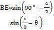
当选用子眼距离底面中心的距离EB为310mm,子眼视场大小为42.2°时,子眼视场
开始重叠点G距离底面中心B的距离与θ之间的关系为BG=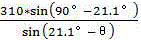

当角度在-20°到10°之间变化时,BG在440mm~1500mm之间变化,基本满足设计需要。When the angle varies between -20° and 10°, the BG varies between 440mm and 1500mm, which basically meets the design needs.
当BG达到最大值1500mm时,通过计算可得到拍摄距离3m远的物体子眼的视场交叠率为26.7%,拍摄距离5m远的物体子眼的视场交叠率为53.4%,子眼交叠比例基本满足设计需要。When the BG reaches the maximum value of 1500mm, it can be obtained by calculation that the field of view overlap rate of the sub-eye of the object at a distance of 3m is 26.7%, and the field of view of the sub-eye of the object at a distance of 5m is 53.4%. The overlap ratio basically meets the design requirements.
具体工作步骤为:The specific working steps are:
(1)飞艇携带复眼相机进入目标区域,通过改变飞艇气囊形状调整子眼拍摄角度。具体包含以下步骤:(1) The airship carries the compound eye camera into the target area, and adjusts the shooting angle of the sub-eye by changing the shape of the airship airbag. Specifically includes the following steps:
(1-1)飞艇移动到目标区域上方,保持3~5m的高度。(1-1) The airship moves above the target area and maintains a height of 3~5m.
(1-2)飞艇的电机带动小齿轮与大齿轮啮合,通过电机的正反旋转,轴承座不同方向的转动。(1-2) The motor of the airship drives the pinion gear to mesh with the big gear, and through the forward and reverse rotation of the motor, the bearing seat rotates in different directions.
(1-3)通过轴承座中心的螺纹与螺杆的啮合,轴承座在延螺杆上下运动,进而实现上下端部两圆盘带动上、下支撑杆的摆动。(1-3) Through the engagement of the thread in the center of the bearing seat and the screw rod, the bearing seat moves up and down along the screw rod, thereby realizing the swing of the upper and lower support rods driven by the two discs at the upper and lower ends.
(1-4)通过上、下支撑杆的摆动改变了气囊形状,飞艇下蒙皮由中点向外发出的任一射线与水平面的夹角θ发生改变。(1-4) The shape of the airbag is changed by the swing of the upper and lower support rods, and the angle θ between any ray emitted from the midpoint of the airship's lower skin and the horizontal plane changes.
(1-5)子眼随着气囊形状改变而呈现出不同的拍摄角度。同时子眼视场的交叠区域也随之发生改变。当θ增大(减小)时,子眼拍摄视场增大(减小),视场交叠区域减少(增大)。(1-5) The sub-eyes show different shooting angles as the shape of the airbag changes. At the same time, the overlapping area of the sub-eye field of view also changes accordingly. When θ increases (decreases), the sub-eye shooting field of view increases (decreases), and the overlapping area of the field of view decreases (increases).
(1-6)调整为合适角度时开始拍摄。(1-6) Start shooting when the angle is adjusted to the right angle.
(2)实施拍摄,各个复眼相机在统一时钟下的同一时刻拍摄,此时数据满足时空一致性,回传拍摄数据,由计算机系统自动重构同一时刻下的三维数字场景,虚拟复眼按动态场景帧率要求每隔(1/帧率)秒拍摄,例如帧率要求为25fps,则拍摄间隔设定为1/25秒,实现实时刷新的动态拍摄。(2) Shooting is carried out. Each compound eye camera shoots at the same time under a unified clock. At this time, the data satisfies the spatial and temporal consistency. The shooting data is returned, and the computer system automatically reconstructs the three-dimensional digital scene at the same time, and the virtual compound eye is based on the dynamic scene. The frame rate is required to be shot every (1/frame rate) second. For example, if the frame rate is required to be 25fps, the shooting interval is set to 1/25 second to achieve dynamic shooting with real-time refresh.
(3)使用尺度不变特征变换算法提取子眼图像中的特征点,再对子眼图像的特征点进行匹配。(3) Use the scale-invariant feature transformation algorithm to extract the feature points in the sub-eye image, and then match the feature points of the sub-eye image.
(4)使用欧式距离法和随机抽样一致性算法筛选特征点匹配对,计算待拼接子眼图像到拼接子眼图像的投影矩阵。(4) Use the Euclidean distance method and the random sampling consistency algorithm to filter the matching pairs of feature points, and calculate the projection matrix from the sub-eye image to be spliced to the spliced sub-eye image.
(5)将待拼接子眼图像进行矩阵变换,使用加权平均法对图像进行融合。(5) Perform matrix transformation on the sub-eye images to be spliced, and use the weighted average method to fuse the images.
(6)将所有子眼图像进行拼接,获取大视场的仿生复眼拼接图像。(6) Splicing all the sub-eye images to obtain a bionic compound eye splicing image with a large field of view.
本说明书中未作详细描述的内容,属于本专业技术人员公知的现有技术。The content not described in detail in this specification belongs to the prior art known to those skilled in the art.
本领域的技术人员容易理解,以上所述仅为本发明的较佳实施例而已,并不用以限制本发明,凡在本发明的精神和原则之内所作的任何修改、等同替换和改进,均应包含在本发明的保护范围之内。Those skilled in the art can easily understand that the above descriptions are only preferred embodiments of the present invention, and are not intended to limit the present invention. Any modifications, equivalent replacements and improvements made within the spirit and principles of the present invention shall be should be included within the protection scope of the present invention.
Claims (6)
Priority Applications (1)
| Application Number | Priority Date | Filing Date | Title |
|---|---|---|---|
| CN201911157140.9A CN110995967B (en) | 2019-11-22 | 2019-11-22 | A virtual compound eye construction system based on variable flying saucer airship |
Applications Claiming Priority (1)
| Application Number | Priority Date | Filing Date | Title |
|---|---|---|---|
| CN201911157140.9A CN110995967B (en) | 2019-11-22 | 2019-11-22 | A virtual compound eye construction system based on variable flying saucer airship |
Publications (2)
| Publication Number | Publication Date |
|---|---|
| CN110995967A CN110995967A (en) | 2020-04-10 |
| CN110995967B true CN110995967B (en) | 2020-11-03 |
Family
ID=70085916
Family Applications (1)
| Application Number | Title | Priority Date | Filing Date |
|---|---|---|---|
| CN201911157140.9A Active CN110995967B (en) | 2019-11-22 | 2019-11-22 | A virtual compound eye construction system based on variable flying saucer airship |
Country Status (1)
| Country | Link |
|---|---|
| CN (1) | CN110995967B (en) |
Families Citing this family (1)
| Publication number | Priority date | Publication date | Assignee | Title |
|---|---|---|---|---|
| CN111503460B (en) * | 2020-04-27 | 2021-02-02 | 武汉理工大学 | Variable-structure eye-healing system and working method |
Citations (11)
| Publication number | Priority date | Publication date | Assignee | Title |
|---|---|---|---|---|
| CN105083522A (en) * | 2015-08-02 | 2015-11-25 | 王建勤 | Disc-shaped inflatable aircraft and flight control method |
| CN107187585A (en) * | 2017-04-18 | 2017-09-22 | 东莞产权交易中心 | a drone |
| CN206750111U (en) * | 2017-04-05 | 2017-12-15 | 杭州东沣科技有限公司 | A kind of dirigible mounting structure and dirigible |
| CN108473190A (en) * | 2015-12-16 | 2018-08-31 | 天空通讯公司 | lighter-than-air platform |
| CN108482635A (en) * | 2018-03-16 | 2018-09-04 | 中国人民解放军国防科技大学 | Inflator wing type aircraft capable of being parked |
| CN109118585A (en) * | 2018-08-01 | 2019-01-01 | 武汉理工大学 | A kind of virtual compound eye camera system and its working method of the building three-dimensional scenic acquisition meeting space-time consistency |
| CN208489931U (en) * | 2018-07-18 | 2019-02-12 | 武汉理工大学 | A compound eye camera for dynamic acquisition |
| CN109808883A (en) * | 2019-01-28 | 2019-05-28 | 深圳市安思科电子科技有限公司 | A kind of unmanned plane of taking photo by plane with defencive function |
| CN209037873U (en) * | 2018-11-06 | 2019-06-28 | 上海天覆信息科技有限公司 | A kind of oblique photograph aerial surveying camera device |
| CN110282132A (en) * | 2016-01-26 | 2019-09-27 | 深圳市大疆创新科技有限公司 | Unmanned Aerial Vehicle and Multi-eye Imaging System |
| CN110341928A (en) * | 2019-08-01 | 2019-10-18 | 智飞智能装备科技东台有限公司 | A kind of multifunction emergency rescue unmanned plane |
Family Cites Families (6)
| Publication number | Priority date | Publication date | Assignee | Title |
|---|---|---|---|---|
| US8505847B2 (en) * | 2011-03-01 | 2013-08-13 | John Ciampa | Lighter-than-air systems, methods, and kits for obtaining aerial images |
| CN205022865U (en) * | 2015-08-14 | 2016-02-10 | 湖北易瓦特科技股份有限公司 | Folding flight equipment of rotor |
| CN206466184U (en) * | 2016-11-23 | 2017-09-05 | 丘之鹏 | Camera mount for UAV tilt photography system |
| KR101913719B1 (en) * | 2017-07-05 | 2018-10-31 | 공주대학교 산학협력단 | Drones With Floating Equipment |
| CN107458572A (en) * | 2017-07-17 | 2017-12-12 | 徐铭阳 | A kind of floating type bionic flapping-wing flying vehicle |
| CN109589520B (en) * | 2018-11-20 | 2021-01-08 | 贵州大学 | High-rise building fire-fighting aircraft capable of transmitting real-time images |
-
2019
- 2019-11-22 CN CN201911157140.9A patent/CN110995967B/en active Active
Patent Citations (11)
| Publication number | Priority date | Publication date | Assignee | Title |
|---|---|---|---|---|
| CN105083522A (en) * | 2015-08-02 | 2015-11-25 | 王建勤 | Disc-shaped inflatable aircraft and flight control method |
| CN108473190A (en) * | 2015-12-16 | 2018-08-31 | 天空通讯公司 | lighter-than-air platform |
| CN110282132A (en) * | 2016-01-26 | 2019-09-27 | 深圳市大疆创新科技有限公司 | Unmanned Aerial Vehicle and Multi-eye Imaging System |
| CN206750111U (en) * | 2017-04-05 | 2017-12-15 | 杭州东沣科技有限公司 | A kind of dirigible mounting structure and dirigible |
| CN107187585A (en) * | 2017-04-18 | 2017-09-22 | 东莞产权交易中心 | a drone |
| CN108482635A (en) * | 2018-03-16 | 2018-09-04 | 中国人民解放军国防科技大学 | Inflator wing type aircraft capable of being parked |
| CN208489931U (en) * | 2018-07-18 | 2019-02-12 | 武汉理工大学 | A compound eye camera for dynamic acquisition |
| CN109118585A (en) * | 2018-08-01 | 2019-01-01 | 武汉理工大学 | A kind of virtual compound eye camera system and its working method of the building three-dimensional scenic acquisition meeting space-time consistency |
| CN209037873U (en) * | 2018-11-06 | 2019-06-28 | 上海天覆信息科技有限公司 | A kind of oblique photograph aerial surveying camera device |
| CN109808883A (en) * | 2019-01-28 | 2019-05-28 | 深圳市安思科电子科技有限公司 | A kind of unmanned plane of taking photo by plane with defencive function |
| CN110341928A (en) * | 2019-08-01 | 2019-10-18 | 智飞智能装备科技东台有限公司 | A kind of multifunction emergency rescue unmanned plane |
Non-Patent Citations (2)
| Title |
|---|
| 基于多旋翼单镜头无人机的城市实景三维重建及精度评估;陈大凯等;《北京测绘》;20180225(第02期);全文 * |
| 复眼相机支撑体结构优化设计及分析;王申奥;《中国优秀硕士学位论文全文数据库 工程科技Ⅱ辑》;20190715;全文 * |
Also Published As
| Publication number | Publication date |
|---|---|
| CN110995967A (en) | 2020-04-10 |
Similar Documents
| Publication | Publication Date | Title |
|---|---|---|
| CN207106926U (en) | A kind of double camera oblique photograph device for airborne vehicle | |
| CN105151290B (en) | A kind of rotor wing unmanned aerial vehicle of high-altitude attitude stabilization four | |
| CN206704563U (en) | A kind of single-lens rotary oblique photograph head of unmanned plane | |
| CN107167117B (en) | A kind of multi-angle double camera oblique photograph apparatus and system | |
| CN206265292U (en) | A kind of unmanned aerial vehicle with retractable landing gear device | |
| CN110995967B (en) | A virtual compound eye construction system based on variable flying saucer airship | |
| CN108216661A (en) | A kind of photoelectric nacelle of two axis, four frame mechanism of voice coil motor driving | |
| CN204705348U (en) | A kind of unmanned plane oblique photograph device | |
| CN210201937U (en) | Image acquisition device | |
| CN113022845B (en) | A coaxial tilt-rotor aircraft and its combined thin-film aircraft | |
| CN103630119B (en) | A kind of aerial survey of unmanned aerial vehicle image motion compensation device and method | |
| CN107117314A (en) | Disk type aircraft | |
| RU130953U1 (en) | UNMANNED AIRCRAFT (OPTIONS) | |
| CN214397285U (en) | Unmanned aerial vehicle of oblique photogrammetry convenient to adjust | |
| CN108415459A (en) | A kind of unmanned plane is around the circumvolant control method and device of target point | |
| CN109263877A (en) | A kind of more rotors are taken photo by plane manned helicopter | |
| CN216748795U (en) | Large-scale live-action three-dimensional modeling system in digital twin city construction | |
| CN110979669B (en) | Variable dish airship unmanned aerial vehicle | |
| CN206523738U (en) | Optical imaging device bearing support | |
| CN221727463U (en) | Electromagnetic scattering regulating and controlling device | |
| CN111186556A (en) | A deformable body and an unmanned aerial vehicle using the same and its control method | |
| CN221835536U (en) | A multi-angle camera device for unmanned aerial vehicles | |
| CN210618488U (en) | A UAV airborne intelligent identification camera | |
| CN206313929U (en) | Flight formula projection arrangement and system | |
| CN119218456B (en) | A UAV for panoramic imaging with a distributed array |
Legal Events
| Date | Code | Title | Description |
|---|---|---|---|
| PB01 | Publication | ||
| PB01 | Publication | ||
| SE01 | Entry into force of request for substantive examination | ||
| SE01 | Entry into force of request for substantive examination | ||
| GR01 | Patent grant | ||
| GR01 | Patent grant |