CN110986879B - A method and system for real-time monitoring of power line tower inclination - Google Patents
A method and system for real-time monitoring of power line tower inclination Download PDFInfo
- Publication number
- CN110986879B CN110986879B CN201911240468.7A CN201911240468A CN110986879B CN 110986879 B CN110986879 B CN 110986879B CN 201911240468 A CN201911240468 A CN 201911240468A CN 110986879 B CN110986879 B CN 110986879B
- Authority
- CN
- China
- Prior art keywords
- data
- gnss
- antenna
- imu
- time
- Prior art date
- Legal status (The legal status is an assumption and is not a legal conclusion. Google has not performed a legal analysis and makes no representation as to the accuracy of the status listed.)
- Active
Links
- 238000012544 monitoring process Methods 0.000 title claims abstract description 31
- 238000000034 method Methods 0.000 title claims abstract description 25
- 238000004364 calculation method Methods 0.000 claims description 46
- 230000005540 biological transmission Effects 0.000 claims description 19
- 230000001360 synchronised effect Effects 0.000 claims description 12
- 241001061260 Emmelichthys struhsakeri Species 0.000 claims description 6
- 238000005070 sampling Methods 0.000 claims description 6
- 238000003089 Pariser Parr Pople method Methods 0.000 description 11
- 238000005516 engineering process Methods 0.000 description 11
- 239000011159 matrix material Substances 0.000 description 9
- 238000004891 communication Methods 0.000 description 6
- 238000012937 correction Methods 0.000 description 6
- 230000008569 process Effects 0.000 description 4
- 238000005259 measurement Methods 0.000 description 3
- 230000007704 transition Effects 0.000 description 3
- 229920000535 Tan II Polymers 0.000 description 2
- 238000013461 design Methods 0.000 description 2
- 230000009977 dual effect Effects 0.000 description 2
- 230000006870 function Effects 0.000 description 2
- 230000004927 fusion Effects 0.000 description 2
- 238000007689 inspection Methods 0.000 description 2
- 230000001133 acceleration Effects 0.000 description 1
- 230000008859 change Effects 0.000 description 1
- 238000006243 chemical reaction Methods 0.000 description 1
- 238000013480 data collection Methods 0.000 description 1
- 238000010586 diagram Methods 0.000 description 1
- 230000000694 effects Effects 0.000 description 1
- 230000010354 integration Effects 0.000 description 1
- 230000001788 irregular Effects 0.000 description 1
- 238000010295 mobile communication Methods 0.000 description 1
- 230000008520 organization Effects 0.000 description 1
- 230000005624 perturbation theories Effects 0.000 description 1
- 238000012545 processing Methods 0.000 description 1
- 230000000750 progressive effect Effects 0.000 description 1
- 230000008054 signal transmission Effects 0.000 description 1
- 238000012546 transfer Methods 0.000 description 1
Images


Classifications
-
- G—PHYSICS
- G01—MEASURING; TESTING
- G01C—MEASURING DISTANCES, LEVELS OR BEARINGS; SURVEYING; NAVIGATION; GYROSCOPIC INSTRUMENTS; PHOTOGRAMMETRY OR VIDEOGRAMMETRY
- G01C9/00—Measuring inclination, e.g. by clinometers, by levels
-
- G—PHYSICS
- G01—MEASURING; TESTING
- G01C—MEASURING DISTANCES, LEVELS OR BEARINGS; SURVEYING; NAVIGATION; GYROSCOPIC INSTRUMENTS; PHOTOGRAMMETRY OR VIDEOGRAMMETRY
- G01C21/00—Navigation; Navigational instruments not provided for in groups G01C1/00 - G01C19/00
- G01C21/10—Navigation; Navigational instruments not provided for in groups G01C1/00 - G01C19/00 by using measurements of speed or acceleration
- G01C21/12—Navigation; Navigational instruments not provided for in groups G01C1/00 - G01C19/00 by using measurements of speed or acceleration executed aboard the object being navigated; Dead reckoning
- G01C21/16—Navigation; Navigational instruments not provided for in groups G01C1/00 - G01C19/00 by using measurements of speed or acceleration executed aboard the object being navigated; Dead reckoning by integrating acceleration or speed, i.e. inertial navigation
- G01C21/165—Navigation; Navigational instruments not provided for in groups G01C1/00 - G01C19/00 by using measurements of speed or acceleration executed aboard the object being navigated; Dead reckoning by integrating acceleration or speed, i.e. inertial navigation combined with non-inertial navigation instruments
-
- G—PHYSICS
- G01—MEASURING; TESTING
- G01S—RADIO DIRECTION-FINDING; RADIO NAVIGATION; DETERMINING DISTANCE OR VELOCITY BY USE OF RADIO WAVES; LOCATING OR PRESENCE-DETECTING BY USE OF THE REFLECTION OR RERADIATION OF RADIO WAVES; ANALOGOUS ARRANGEMENTS USING OTHER WAVES
- G01S19/00—Satellite radio beacon positioning systems; Determining position, velocity or attitude using signals transmitted by such systems
- G01S19/38—Determining a navigation solution using signals transmitted by a satellite radio beacon positioning system
- G01S19/39—Determining a navigation solution using signals transmitted by a satellite radio beacon positioning system the satellite radio beacon positioning system transmitting time-stamped messages, e.g. GPS [Global Positioning System], GLONASS [Global Orbiting Navigation Satellite System] or GALILEO
- G01S19/42—Determining position
- G01S19/45—Determining position by combining measurements of signals from the satellite radio beacon positioning system with a supplementary measurement
- G01S19/47—Determining position by combining measurements of signals from the satellite radio beacon positioning system with a supplementary measurement the supplementary measurement being an inertial measurement, e.g. tightly coupled inertial
Landscapes
- Engineering & Computer Science (AREA)
- Radar, Positioning & Navigation (AREA)
- Remote Sensing (AREA)
- Physics & Mathematics (AREA)
- General Physics & Mathematics (AREA)
- Computer Networks & Wireless Communication (AREA)
- Automation & Control Theory (AREA)
- Position Fixing By Use Of Radio Waves (AREA)
- Navigation (AREA)
Abstract
本发明公开了一种电力线塔倾斜实时监测方法及系统。该方法包括:获取惯性传感器采集到的IMU数据和双天线GNSS系统提供的GNSS数据,其中,惯性传感器和双天线GNSS系统均安装在电力线塔上;将IMU数据与GNSS数据同步;将同步后的IMU数据与GNSS数据实时传输至控制系统端;控制系统端根据IMU数据对第一参数进行解算,第一参数包括;第一天线的位置、速度和航向角;控制系统端根据GNSS数据对第二参数进行解算,第二参数包括第一天线的位置、速度和双天线间基线的航向角;基于扩展卡尔曼滤波算法,对第一参数与第二参数进行松组合解算,确定电力线塔的位置、速度和航向角;根据电力线塔航向角确定电力线塔的倾斜幅度。本发明能够对电力线塔倾斜情况进行实时的高精度监测。

The invention discloses a real-time monitoring method and system for the tilt of a power line tower. The method includes: acquiring IMU data collected by an inertial sensor and GNSS data provided by a dual-antenna GNSS system, wherein both the inertial sensor and the dual-antenna GNSS system are installed on a power line tower; synchronizing the IMU data with the GNSS data; The IMU data and GNSS data are transmitted to the control system end in real time; the control system end calculates the first parameter according to the IMU data, and the first parameter includes; the position, speed and heading angle of the first antenna; Two parameters are calculated. The second parameter includes the position and velocity of the first antenna and the heading angle of the baseline between the two antennas. Based on the extended Kalman filter algorithm, the first parameter and the second parameter are loosely combined and calculated to determine the power line tower. The position, speed and heading angle of the power line tower; determine the inclination of the power line tower according to the heading angle of the power line tower. The present invention can perform real-time high-precision monitoring on the inclination of the power line tower.
Description
技术领域technical field
本发明涉及电力设备技术领域,特别是涉及一种电力线塔倾斜实时监测方法及系统。The invention relates to the technical field of electric power equipment, in particular to a method and system for real-time monitoring of the tilt of a power line tower.
背景技术Background technique
高压电力线塔的实时倾斜幅度监测是维护输电安全的核心技术支撑。现有的高压电力塔的倾斜监测和巡检方法,主要基于二者之一,且主要以定期或不定期巡检为主,一方面难以实现对电力塔倾斜状态的连续监测,另一方也不能满足实时高精度的监测需要,很难满足防患于未然的输电安全需要。Real-time inclination monitoring of high-voltage power line towers is the core technical support for maintaining power transmission safety. The existing tilt monitoring and inspection methods of high-voltage power towers are mainly based on one of the two, and are mainly based on regular or irregular inspections. To meet the real-time and high-precision monitoring needs, it is difficult to meet the transmission safety needs of preventing problems before they occur.
发明内容SUMMARY OF THE INVENTION
本发明的目的是提供一种电力线塔倾斜实时监测方法及系统,能够对电力线塔倾斜情况进行实时的高精度监测。The purpose of the present invention is to provide a real-time monitoring method and system for the inclination of a power line tower, which can perform real-time high-precision monitoring of the inclination of a power line tower.
为实现上述目的,本发明提供了如下方案:For achieving the above object, the present invention provides the following scheme:
一种电力线塔倾斜实时监测方法,包括:A real-time monitoring method for the tilt of a power line tower, comprising:
获取惯性传感器采集到的IMU数据以及双天线GNSS系统提供的GNSS数据,所述惯性传感器和所述双天线GNSS系统均安装在电力线塔上;Obtaining the IMU data collected by the inertial sensor and the GNSS data provided by the dual-antenna GNSS system, the inertial sensor and the dual-antenna GNSS system are both installed on the power line tower;
将所述IMU数据与所述GNSS数据同步;synchronizing the IMU data with the GNSS data;
将同步后的IMU数据与GNSS数据实时的传输至控制系统端;Real-time transmission of synchronized IMU data and GNSS data to the control system;
控制系统端根据所述IMU数据对第一参数进行解算,所述第一参数包括;第一天线的位置、速度和航向角;The control system end calculates the first parameter according to the IMU data, and the first parameter includes: the position, speed and heading angle of the first antenna;
控制系统端根据所述GNSS数据对第二参数进行解算,所述第二参数包括第一天线的位置、速度和双天线间基线的航向角;The control system end calculates the second parameter according to the GNSS data, and the second parameter includes the position and speed of the first antenna and the heading angle of the baseline between the two antennas;
基于扩展卡尔曼滤波算法,对根据IMU数据解算得到的第一参数与根据GNSS数据解算得到的第二参数进行松组合解算,确定电力线塔的位置、速度和航向角;Based on the extended Kalman filter algorithm, a loose combination of the first parameter obtained from the IMU data and the second parameter obtained from the GNSS data is calculated to determine the position, speed and heading angle of the power line tower;
根据所述电力线塔的航向角确定所述电力线塔的倾斜幅度。The inclination magnitude of the power line tower is determined according to the heading angle of the power line tower.
可选的,所述将所述IMU数据与所述GNSS数据同步,具体包括:Optionally, the synchronizing the IMU data with the GNSS data specifically includes:
在FPGA板卡上,同时接入GNSS信号和IMU信号;On the FPGA board, access the GNSS signal and the IMU signal at the same time;
从GNSS信号中解码出GPS/BDS/GLONASS/Galileo时间信息;Decode GPS/BDS/GLONASS/Galileo time information from GNSS signals;
确定传入FPGA板卡中的GNSS信号与IMU信号的时间差;Determine the time difference between the incoming GNSS signal and the IMU signal in the FPGA board;
根据解码出GPS/BDS/GLONASS/Galileo时间信息以及所述时间差,计算所述IMU信号的时间信息,记为IMU信号初始时间;Calculate the time information of the IMU signal according to the decoded GPS/BDS/GLONASS/Galileo time information and the time difference, which is recorded as the initial time of the IMU signal;
根据所述IMU信号初始时间,结合IMU采样率,确定后续输入FPGA板卡的IMU数据的时间信息。According to the initial time of the IMU signal and in combination with the sampling rate of the IMU, the time information of the IMU data subsequently input to the FPGA board is determined.
可选的,所述将同步后的IMU数据与GNSS数据传输至控制系统端,具体包括:Optionally, the transmission of the synchronized IMU data and GNSS data to the control system side specifically includes:
将同步后的IMU数据与GNSS数据通过4G/5G实时的传输至控制系统端。The synchronized IMU data and GNSS data are transmitted to the control system in real time through 4G/5G.
可选的,在所述根据所述GNSS数据对第二参数进行解算之前,还包括:Optionally, before the second parameter is calculated according to the GNSS data, the method further includes:
获取IGS服务中心解算的GNSS系统的参数,所述参数包括精密轨道、实时精密钟差、电离层参数、卫星码间偏差、卫星未校正相位偏差。The parameters of the GNSS system calculated by the IGS service center are obtained, and the parameters include precise orbit, real-time precise clock error, ionospheric parameters, satellite inter-symbol deviation, and satellite uncorrected phase deviation.
可选的,所述根据所述GNSS数据对第二参数进行解算,具体包括:Optionally, the calculating the second parameter according to the GNSS data specifically includes:
根据第一天线的GNSS数据以及IGS服务中心解算的GNSS系统的参数,对第一天线进行实时的PPP定位和速度解算,得到第一天线在地心地固坐标系下的绝对位置和速度;According to the GNSS data of the first antenna and the parameters of the GNSS system calculated by the IGS service center, real-time PPP positioning and speed calculation are performed on the first antenna to obtain the absolute position and speed of the first antenna in the geocentric fixed coordinate system;
利用第一天线的GNSS数据和第二天线的GNSS数据,以第一天线为基准站,以第二天线为流动站,进行超短基线RTK解算,得到第一天线与第二天线之间的基线向量;Using the GNSS data of the first antenna and the GNSS data of the second antenna, taking the first antenna as the reference station and the second antenna as the rover, perform ultra-short baseline RTK calculation to obtain the difference between the first antenna and the second antenna. baseline vector;
将所述基线向量转换到导航坐标系,并确定基线向量在导航坐标系中的航向角。Convert the baseline vector to the navigation coordinate system and determine the heading angle of the baseline vector in the navigation coordinate system.
本发明还提供了一种电力线塔倾斜实时监测系统,包括:控制系统端、安装于电力线塔上的惯性传感器和双天线GNSS系统、FPGA板卡、数据传输模块;其中,所述FPGA板卡包括数据获取模块和数据同步模块,所述控制系统端包括IMU数据解算模块、GNSS数据解算模块、松组合解算模块和倾斜幅度确定模块;The present invention also provides a real-time monitoring system for the tilt of a power line tower, including: a control system end, an inertial sensor and a dual-antenna GNSS system installed on the power line tower, an FPGA board, and a data transmission module; wherein the FPGA board includes a data acquisition module and a data synchronization module, the control system end includes an IMU data calculation module, a GNSS data calculation module, a loose combination calculation module and a tilt amplitude determination module;
所述数据获取模块,用于获取惯性传感器采集到的IMU数据以及双天线GNSS系统提供的GNSS数据;The data acquisition module is used to acquire the IMU data collected by the inertial sensor and the GNSS data provided by the dual-antenna GNSS system;
所述数据同步模块,用于将所述IMU数据与所述GNSS数据同步;the data synchronization module, for synchronizing the IMU data with the GNSS data;
所述数据传输模块,用于将同步后的IMU数据与GNSS数据传输至控制系统端;The data transmission module is used to transmit the synchronized IMU data and GNSS data to the control system end;
所述IMU数据解算模块,用于根据所述IMU数据对第一参数进行解算,所述第一参数包括;第一天线的位置、速度和航向角;The IMU data calculation module is configured to calculate a first parameter according to the IMU data, where the first parameter includes: the position, speed and heading angle of the first antenna;
所述GNSS数据解算模块,用于根据所述GNSS数据对第二参数进行解算,所述第二参数包括第一天线的位置、速度和双天线间基线的航向角;The GNSS data calculation module is configured to calculate a second parameter according to the GNSS data, where the second parameter includes the position and speed of the first antenna and the heading angle of the baseline between the two antennas;
所述松组合解算模块,用于基于扩展卡尔曼滤波算法,对所述第一参数与所述第二参数进行松组合解算,确定电力线塔的位置、速度和航向角;The loose combination calculation module is configured to perform loose combination calculation on the first parameter and the second parameter based on the extended Kalman filter algorithm, and determine the position, speed and heading angle of the power line tower;
所述倾斜幅度确定模块,用于根据所述电力线塔的航向角确定所述电力线塔的倾斜幅度。The inclination magnitude determination module is configured to determine the inclination magnitude of the power line tower according to the heading angle of the power line tower.
可选的,所述数据同步模块,具体包括:Optionally, the data synchronization module specifically includes:
信号接入单元,用于在FPGA板卡上,同时接入GNSS信号和IMU信号;The signal access unit is used to simultaneously access the GNSS signal and the IMU signal on the FPGA board;
解码单元,用于从GNSS信号中解码出GPS/BDS/GLONASS/Galileo时间信息;A decoding unit for decoding GPS/BDS/GLONASS/Galileo time information from the GNSS signal;
时间差确定单元,用于确定传入FPGA板卡中的GNSS信号与IMU信号的时间差;The time difference determination unit is used to determine the time difference between the GNSS signal and the IMU signal passed into the FPGA board;
IMU信号初始时间信息同步单元,用于根据解码出GPS/BDS/GLONASS/Galileo时间信息以及所述时间差,计算所述IMU信号的时间信息,记为IMU信号初始时间;The IMU signal initial time information synchronization unit is used to calculate the time information of the IMU signal according to the decoded GPS/BDS/GLONASS/Galileo time information and the time difference, which is recorded as the initial time of the IMU signal;
IMU信号时间信息同步单元,用于根据所述IMU信号初始时间,结合IMU采样率,确定后续输入FPGA板卡的IMU数据的时间信息。The IMU signal time information synchronization unit is configured to determine the time information of the IMU data subsequently input to the FPGA board according to the initial time of the IMU signal and in combination with the IMU sampling rate.
可选的,所述数据传输模块,具体包括:Optionally, the data transmission module specifically includes:
数据传输单元,用于将同步后的IMU数据与GNSS数据通过4G/5G传输至控制系统端。The data transmission unit is used to transmit the synchronized IMU data and GNSS data to the control system through 4G/5G.
可选的,所述系统还包括:Optionally, the system further includes:
GNSS系统参数获取单元,用于获取IGS服务中心解算的GNSS系统的参数,所述参数包括精密轨道、实时精密钟差、电离层参数、卫星码间偏差、卫星未校正相位偏差。The GNSS system parameter acquisition unit is used to acquire the parameters of the GNSS system calculated by the IGS service center, the parameters include precise orbit, real-time precise clock error, ionospheric parameters, satellite inter-symbol deviation, and satellite uncorrected phase deviation.
可选的,所述GNSS数据解算模块,具体包括:Optionally, the GNSS data calculation module specifically includes:
位置速度解算单元,用于根据第一天线的GNSS数据以及IGS服务中心解算的GNSS系统的参数,对第一天线进行实时的PPP定位和速度解算,得到第一天线在地心地固坐标系下的绝对位置和速度;The position and velocity calculation unit is used to perform real-time PPP positioning and velocity calculation for the first antenna according to the GNSS data of the first antenna and the parameters of the GNSS system calculated by the IGS service center, and obtain the fixed coordinates of the first antenna at the center of the earth absolute position and velocity under the system;
基线向量确定单元,用于利用第一天线的GNSS数据和第二天线的GNSS数据,以第一天线为基准站,以第二天线为流动站,进行超短基线RTK解算,得到第一天线与第二天线之间的基线向量;The baseline vector determination unit is used for using the GNSS data of the first antenna and the GNSS data of the second antenna, taking the first antenna as the reference station and the second antenna as the rover, to perform ultra-short baseline RTK calculation to obtain the first antenna the baseline vector with the second antenna;
航向角解算单元,用于将所述基线向量转换到导航坐标系,并确定基线向量在导航坐标系中的航向角。The heading angle calculation unit is used for converting the baseline vector into the navigation coordinate system, and determining the heading angle of the baseline vector in the navigation coordinate system.
根据本发明提供的具体实施例,本发明公开了以下技术效果:本发明提供的电力线塔倾斜实时监测方法及系统,将安装在电力线塔上的惯性传感器和双天线GNSS系统采集到的IMU数据和GNSS数据通过4G/5G通信技术实时地传输至控制系统端,控制系统端首先对主天线GNSS数据进行实时PPP解算,获得该天线的精确坐标;其次利用双天线GNSS数据进行RTK解算,获得高精度基线结果,从而计算双天线所确定的航向姿态角;以主天线的位置、双天线航向姿态和IMU数据,进行GNSS/INS松组合解算,解算电力塔的位置、速度和姿态,从而实现了对高压电力线塔的绝对位置和倾斜情况的实时高精度、快速、有效监测。According to the specific embodiments provided by the present invention, the present invention discloses the following technical effects: the method and system for real-time monitoring of the tilt of a power line tower provided by the present invention, the IMU data collected by the inertial sensor installed on the power line tower and the dual-antenna GNSS system and GNSS data is transmitted to the control system in real time through 4G/5G communication technology. The control system first performs real-time PPP calculation on the GNSS data of the main antenna to obtain the precise coordinates of the antenna; secondly, the dual-antenna GNSS data is used for RTK calculation to obtain High-precision baseline results, so as to calculate the heading attitude angle determined by the dual antennas; based on the position of the main antenna, the heading attitude of the dual antennas and the IMU data, the GNSS/INS loose combination calculation is performed to calculate the position, speed and attitude of the power tower, Thereby, the real-time high-precision, fast and effective monitoring of the absolute position and inclination of the high-voltage power line tower is realized.
附图说明Description of drawings
为了更清楚地说明本发明实施例或现有技术中的技术方案,下面将对实施例中所需要使用的附图作简单地介绍,显而易见地,下面描述中的附图仅仅是本发明的一些实施例,对于本领域普通技术人员来讲,在不付出创造性劳动的前提下,还可以根据这些附图获得其他的附图。In order to more clearly illustrate the embodiments of the present invention or the technical solutions in the prior art, the accompanying drawings required in the embodiments will be briefly introduced below. Obviously, the drawings in the following description are only some of the present invention. In the embodiments, for those of ordinary skill in the art, other drawings can also be obtained according to these drawings without any creative effort.
图1为本发明实施例中电力线塔倾斜实时监测系统中部分组成元件的连接关系示意图;1 is a schematic diagram of the connection relationship of some components in the real-time monitoring system for the tilt of a power line tower in an embodiment of the present invention;
图2为本发明实施例中电力线塔倾斜实时监测方法流程图。FIG. 2 is a flowchart of a method for real-time monitoring of the tilt of a power line tower in an embodiment of the present invention.
具体实施方式Detailed ways
下面将结合本发明实施例中的附图,对本发明实施例中的技术方案进行清楚、完整地描述,显然,所描述的实施例仅仅是本发明一部分实施例,而不是全部的实施例。基于本发明中的实施例,本领域普通技术人员在没有做出创造性劳动前提下所获得的所有其他实施例,都属于本发明保护的范围。The technical solutions in the embodiments of the present invention will be clearly and completely described below with reference to the accompanying drawings in the embodiments of the present invention. Obviously, the described embodiments are only a part of the embodiments of the present invention, rather than all the embodiments. Based on the embodiments of the present invention, all other embodiments obtained by those of ordinary skill in the art without creative efforts shall fall within the protection scope of the present invention.
本发明的目的是提供一种电力线塔倾斜实时监测方法及系统,能够对电力线塔倾斜情况进行实时的高精度监测。The purpose of the present invention is to provide a real-time monitoring method and system for the inclination of a power line tower, which can perform real-time high-precision monitoring of the inclination of a power line tower.
为使本发明的上述目的、特征和优点能够更加明显易懂,下面结合附图和具体实施方式对本发明作进一步详细的说明。In order to make the above objects, features and advantages of the present invention more clearly understood, the present invention will be described in further detail below with reference to the accompanying drawings and specific embodiments.
下面先对本发明涉及到的一些专业术语进行解释说明:Some technical terms involved in the present invention are explained below first:
4G/5G:4G/5G通信,The 4/5th Generation Mobile Communication Technology;4G/5G: 4G/5G communication, The 4/5th Generation Mobile Communication Technology;
GPS:全球定位系统,Global Positioning System;GPS: Global Positioning System, Global Positioning System;
GLONASS:全球导航卫星系统,GLObal NAvigation Satellite System;GLONASS: Global Navigation Satellite System, GLObal NAvigation Satellite System;
BDS3:第三代北斗卫星导航系统,3th BeiDou Satellite Navigation System;BDS3: 3th BeiDou Satellite Navigation System;
Galileo:伽利略卫星导航系统,Galileo Satellite Navigation System;Galileo: Galileo Satellite Navigation System, Galileo Satellite Navigation System;
GNSS:全球卫星导航系统,Global Navigation Satellite Systems;GNSS: Global Navigation Satellite System, Global Navigation Satellite Systems;
IGS:国际GNSS服务组织,International GNSS Service Center;IGS: International GNSS Service Organization, International GNSS Service Center;
IMU:惯性测量单元,Inertial Measurement Unit;INS:惯性导航系统,InertialNavigation System;IMU: Inertial Measurement Unit, Inertial Measurement Unit; INS: Inertial Navigation System, InertialNavigation System;
FPGA:现场可编程阵列,Field Programmable Gate Array;FPGA: Field Programmable Array, Field Programmable Gate Array;
RT-PPP:实时精密单点定位,Real-time Precise Point Positioning;RT-PPP: Real-time Precise Point Positioning; Real-time Precise Point Positioning;
RTK:实时动态差分定位技术,Real-time Kinematic;RTK: real-time dynamic differential positioning technology, Real-time Kinematic;
LCI:松组合,Loose Coupled Integration。LCI: Loose Coupled Integration.
本发明由4G/5G通信模块、低成本惯性传感器、双天线多系统GNSS(包括BDS、GPS、GLONASS、Galileo等)接收机共同构成用户端数据采集和播发系统,以GNSS系统时间为基准,在FPGA板卡上计算GNSS输入信号和IMU输入信号的时间差,确定IMU数据的时间,完成GNSS/IMU数据的时间同步工作。利用4G/5G通信模块,将时间同步后的双天线多系统GNSS伪距/载波/多普勒信息和IMU采集的比力和角速度信息传输到控制系统端,在控制系统端,利用实时PPP精密单点定位和RTK高精度基线算法确定GNSS双天线的绝对位置和双天线的姿态,并综合利用双天线姿态数据、双天线GNSS RTK位置数据、INS数据进行松组合结算,从而实现对高压电力线塔的绝对位置和倾斜情况的实时高精度、快速、有效监测。The present invention consists of a 4G/5G communication module, a low-cost inertial sensor, and a dual-antenna multi-system GNSS (including BDS, GPS, GLONASS, Galileo, etc.) receiver to form a user-end data collection and broadcast system. The FPGA board calculates the time difference between the GNSS input signal and the IMU input signal, determines the time of the IMU data, and completes the time synchronization of the GNSS/IMU data. Using the 4G/5G communication module, the time-synchronized dual-antenna multi-system GNSS pseudorange/carrier/Doppler information and the specific force and angular velocity information collected by the IMU are transmitted to the control system side. At the control system side, the real-time PPP precision is used. Single-point positioning and RTK high-precision baseline algorithms determine the absolute position of the GNSS dual-antenna and the attitude of the dual-antenna, and comprehensively use the dual-antenna attitude data, dual-antenna GNSS RTK position data, and INS data for loose combination settlement, so as to realize the high-voltage power line tower. Real-time high-precision, fast and effective monitoring of the absolute position and tilt of the system.
如图1所示,以低成本惯性传感器2为中心,建立前-右-下载体坐标系,将双天线多系统GNSS接收机1的天线r1和天线r2安装在前/x轴上,其中天线r1尽可能靠近IMU,并量取天线r1到IMU的杆臂
在实施例中,如图2所示,本发明提供的电力线塔倾斜实时监测方法包括以下步骤:In an embodiment, as shown in FIG. 2 , the real-time monitoring method for the tilt of a power line tower provided by the present invention includes the following steps:
步骤201:获取惯性传感器采集到的IMU数据以及双天线GNSS系统提供的GNSS数据,所述惯性传感器和所述双天线GNSS系统均安装在电力线塔上;Step 201: Acquire IMU data collected by an inertial sensor and GNSS data provided by a dual-antenna GNSS system, where the inertial sensor and the dual-antenna GNSS system are both installed on power line towers;
步骤202:将所述IMU数据与所述GNSS数据同步;Step 202: Synchronize the IMU data with the GNSS data;
步骤203:将同步后的IMU数据与GNSS数据实时的传输至控制系统端;Step 203: transmitting the synchronized IMU data and GNSS data to the control system end in real time;
步骤204:控制系统端根据所述IMU数据对第一参数进行解算,所述第一参数包括;第一天线的位置、速度和航向角;Step 204: the control system end calculates the first parameter according to the IMU data, the first parameter includes: the position, speed and heading angle of the first antenna;
步骤205:控制系统端根据所述GNSS数据对第二参数进行解算,所述第二参数包括第一天线的位置、速度和双天线间基线的航向角;Step 205: the control system end calculates the second parameter according to the GNSS data, and the second parameter includes the position and speed of the first antenna and the heading angle of the baseline between the two antennas;
步骤206:基于扩展卡尔曼滤波算法,对根据IMU数据解算得到的第一参数与根据GNSS数据解算得到的第二参数进行松组合解算,确定电力线塔的位置、速度和航向角;Step 206: Based on the extended Kalman filter algorithm, the first parameter calculated according to the IMU data and the second parameter obtained according to the GNSS data calculation are loosely combined and calculated to determine the position, speed and heading angle of the power line tower;
步骤207:根据所述电力线塔的航向角确定所述电力线塔的倾斜幅度。Step 207: Determine the inclination amplitude of the power line tower according to the heading angle of the power line tower.
在上述实施例中,步骤202可以以如下方式实现:In the above embodiment, step 202 can be implemented in the following manner:
基于电子信号传输理论,在FPGA板卡上,同时接入双天线多系统GNSS信号和IMU信号,利用传入FPGA板卡中两个信号的时间差值和从GNSS信号中解码出的GPS/BDS/GLONASS/Galileo时间信息,计算当前IMU信号的时间。同时,基于IMU稳定的PPS信号和计算出的IMU初始时间,按照IMU采样率,给后续输入的IMU数据逐个进行时间同步。Based on the theory of electronic signal transmission, on the FPGA board, the dual-antenna multi-system GNSS signal and IMU signal are simultaneously connected, and the time difference between the two signals in the incoming FPGA board and the GPS/BDS decoded from the GNSS signal are used. /GLONASS/Galileo time information, calculate the time of the current IMU signal. At the same time, based on the stable PPS signal of the IMU and the calculated initial time of the IMU, and according to the sampling rate of the IMU, time synchronization is performed one by one for the subsequent input IMU data.
在上述实施例中,步骤203可以以如下方式实现:In the above embodiment, step 203 can be implemented in the following manner:
基于4G/5G通信技术理论和数字编码/解码技术,将观测到的双天线多系统GNSS数据和时间同步后的IMU数据实时传输回控制端系统,并按照GNSS数据格式和IMU数据格式进行解码。Based on 4G/5G communication technology theory and digital encoding/decoding technology, the observed dual-antenna multi-system GNSS data and time-synchronized IMU data are transmitted back to the control terminal system in real time, and decoded according to the GNSS data format and IMU data format.
在上述实施例中,在步骤205之前,还包括:In the above embodiment, before
基于网络数据传输技术和多系统GNSS实时精密定轨理论,将IGS服务中心解算的多系统GNSS实时卫星产品(包括精密轨道、实时精密钟差、电离层参数、卫星码间偏差、卫星未校正相位偏差)实时传入控制系统。Based on network data transmission technology and multi-system GNSS real-time precise orbit determination theory, the multi-system GNSS real-time satellite products (including precise orbit, real-time precise clock error, ionospheric parameters, satellite inter-symbol deviation, satellite uncorrected) calculated by the IGS service center phase deviation) into the control system in real time.
在上述实施例中,步骤205可以以如下方式实现:In the above embodiment, step 205 can be implemented in the following manner:
基于实时精密单点定位理论,利用传入的第一天线r1的实时多系统GNSS数据(伪距、载波和多普勒)和实时精密卫星产品,进行实时PPP定位和测速解算,获得地心地固坐标系下(Earth centered earth fixed frame,e系)高压电力线塔的实时高精度的绝对位置
基于双差GNSS基线解算理论,以r1天线为基准站,以GNSS系统的第二天线(r2)为流动站,进行超短基线RTK解算,获得r2天线的位置

基于空间坐标系转换原理,以r1天线位置为中心,将r1和r2天线之间的基线向量(ΔLe)转换到导航坐标系(North-East-Down,简称N-E-D,记为navigation frame,即n系),获得n系下的基线向量ΔLn=(ΔNr1-r2,ΔEr1-r2,ΔDr1-r2)T;Based on the principle of space coordinate system conversion, taking the r1 antenna position as the center, the baseline vector (ΔL e ) between the r1 and r2 antennas is converted to the navigation coordinate system (North-East-Down, referred to as NED, denoted as navigation frame, that is, n system), obtain the baseline vector ΔL n =(ΔN r1-r2 ,ΔE r1-r2 ,ΔD r1-r2 ) T under the n system;
基于空间航向角定义,利用n系下的基线向量ΔLn,计算r1和r2天线所确定基线对应的航向角Ψr1-r2=a tan 2(ΔEr1-r2,ΔNr1-r2),其中a tan 2是C/C++语言中用于计算方位角的函数,其返回值在-π~+π之间;Based on the definition of the space heading angle, using the baseline vector ΔL n in the n system, calculate the heading angle corresponding to the baseline determined by the r1 and r2 antennas Ψ r1-r2 =a tan 2(ΔE r1-r2 ,ΔN r1-r2 ), where a tan 2 is a function used to calculate the azimuth angle in the C/C++ language, and its return value is between -π~+π;
在上述实施例中,步骤205可以以如下方式实现:In the above embodiment, step 205 can be implemented in the following manner:
基于多源数据融合理论和扩展卡尔曼滤波理论,利用GNSS位置、r1和r2天线确定的航向角和IMU数据进行松组合解算。在扩展卡尔曼滤波理论中,松组合观测方程和状态方程可分别表示为:Based on the multi-source data fusion theory and the extended Kalman filter theory, a loose combination solution is performed using the GNSS position, the heading angle determined by the r1 and r2 antennas, and the IMU data. In the extended Kalman filter theory, the loosely combined observation equation and state equation can be expressed as:
ZLCI,k=HLCI,kXLCI,k+ηLCI,k,ηLCI,k~N(0,RLCI,k) (1)Z LCI,k =H LCI,k X LCI,k +η LCI,k, η LCI,k ~N(0,R LCI,k ) (1)
XLCI,k=ΦLCI,k/k-1XLCI,k-1+μLCI,k-1,μLCI,k-1~N(0,QLCI,k-1) (2)X LCI,k =Φ LCI,k/k-1 X LCI,k-1 +μ LCI,k-1 ,μ LCI,k-1 ~N(0,Q LCI,k-1 ) (2)
式(1)和(2)对应的平差解和对应的方差可分别表示为:The adjustment solutions and the corresponding variances corresponding to equations (1) and (2) can be expressed as:
XLCI,k=ΦLCI,k/k-1XLCI,k-1+KLCI,k(ZLCI,k-HLCI,kΦLCI,k/k-1XLCI,k-1) (3)X LCI,k =Φ LCI,k/k-1 X LCI,k-1 +K LCI,k (Z LCI,k -H LCI,k Φ LCI,k/k-1 X LCI,k-1 ) ( 3)

其中,in,


式中,ZLCI、XLCI、HLCI和Φk,k-1分别表示松组合(LCI)的观测新息向量、状态参数向量、设计系数矩阵和由k-1时刻状态参数向量预测k时刻状态参数向量的状态转移矩阵;KLCI,k表示k时刻的卡尔曼滤波增益矩阵;ηLCI和μk-1分别表示松组合的观测向量噪声和状态噪声,其先验方差分别为RLCI和Qk;N表示高斯正态分布;XLCI表示状态向量:In the formula, Z LCI , X LCI , H LCI and Φ k,k-1 represent the observation innovation vector, state parameter vector, design coefficient matrix of the loose combination (LCI), and the state parameter vector at time k-1 predicts time k, respectively. The state transition matrix of the state parameter vector; K LCI,k represents the Kalman filter gain matrix at time k; η LCI and μ k-1 represent the observation vector noise and state noise of the loose combination, respectively, and their prior variances are R LCI and Q k ; N means Gaussian normal distribution; X LCI means state vector:

式中,δΨ表示姿态改正数向量(包括横滚角改正时、俯仰角改正数和航向角改正数);δBa和δBg表示加速度计(accelerometer)和陀螺仪(gyroscope)零偏(Bias)改正数向量;δSa和δSg分别表示加速度计和陀螺仪比例因子(Scale factor)改正数向量。观测新息向量(ZLCI)由航向约束方程、位置方程、速度方程三部分构成:In the formula, δΨ represents the attitude correction vector (including the roll angle correction, the pitch angle correction and the heading angle correction); δB a and δB g represent the accelerometer and gyroscope bias (Bias) Correction number vector; δS a and δS g represent the accelerometer and gyroscope scale factor correction number vector, respectively. The observation innovation vector (Z LCI ) consists of three parts: the heading constraint equation, the position equation, and the velocity equation:
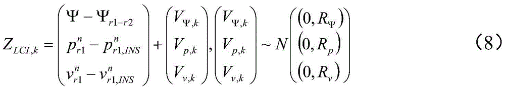
式中,Ψ表示用由INS力学编排计算的航向角;


式中,


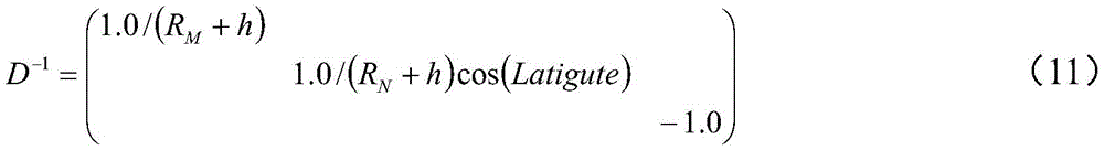
式中,RN和RM分别表示子午圈曲率半径和卯酉圈曲率半径,h表示当前IMU对应的高程,latitude表示IMU所在位置对应的纬度。In the formula, R N and R M represent the radius of curvature of the meridian circle and the radius of curvature of the unitary circle, respectively, h represents the elevation corresponding to the current IMU, and latitude represents the latitude corresponding to the location of the IMU.
根据误差扰动理论,对式(8)进行误差扰动


式中,fb、gn、

式中,x=(δBg,δBa,δSg,δSa),τ表示一阶高斯马尔科夫过程相关时间,∈表示一阶高斯马尔科夫过程噪声。In the formula, x=(δB g ,δB a ,δS g ,δS a ), τ represents the correlation time of the first-order Gaussian Markov process, and ∈ represents the noise of the first-order Gaussian Markov process.
基于式(12)~(15),即可得到状态转移系数矩阵。据此,根据式(3)即可计算得到高压电力线塔的高精度三维位置、速度和姿态信息,由于电力线塔的倾斜幅度可通过计算的姿态角直接反应,在4G/5G实时通讯技术的支撑下,双天线多系统GNSS PPP-RTK/INS实时数据处理算法可用于存在倾斜危险的电力塔的实时定位和监测预警。Based on equations (12) to (15), the state transition coefficient matrix can be obtained. Accordingly, the high-precision three-dimensional position, velocity and attitude information of the high-voltage power line tower can be calculated according to formula (3). The dual-antenna multi-system GNSS PPP-RTK/INS real-time data processing algorithm can be used for real-time positioning and monitoring and early warning of power towers that are in danger of tilting.
本发明还提供了一种电力线塔倾斜实时监测系统,该系统包括:控制系统端、安装于电力线塔上的惯性传感器和双天线GNSS系统、FPGA板卡、数据传输模块;其中,所述FPGA板卡包括数据获取模块和数据同步模块,所述控制系统端包括IMU数据解算模块、GNSS数据解算模块、松组合解算模块和倾斜幅度确定模块;The invention also provides a real-time monitoring system for the tilt of a power line tower. The system includes: a control system end, an inertial sensor and a dual-antenna GNSS system installed on the power line tower, an FPGA board, and a data transmission module; wherein, the FPGA board The card includes a data acquisition module and a data synchronization module, and the control system end includes an IMU data calculation module, a GNSS data calculation module, a loose combination calculation module and an inclination amplitude determination module;
所述数据获取模块,用于获取惯性传感器采集到的IMU数据以及双天线GNSS系统提供的GNSS数据;The data acquisition module is used to acquire the IMU data collected by the inertial sensor and the GNSS data provided by the dual-antenna GNSS system;
所述数据同步模块,用于将所述IMU数据与所述GNSS数据同步;the data synchronization module, for synchronizing the IMU data with the GNSS data;
所述数据传输模块,用于将同步后的IMU数据与GNSS数据实时的传输至控制系统端;The data transmission module is used to transmit the synchronized IMU data and GNSS data to the control system end in real time;
所述IMU数据解算模块,用于根据所述IMU数据对第一参数进行解算,所述第一参数包括;第一天线的位置、速度和航向角;The IMU data calculation module is configured to calculate a first parameter according to the IMU data, where the first parameter includes: the position, speed and heading angle of the first antenna;
所述GNSS数据解算模块,用于根据所述GNSS数据对第二参数进行解算,所述第二参数包括第一天线的位置、速度和双天线间基线的航向角;The GNSS data calculation module is configured to calculate a second parameter according to the GNSS data, where the second parameter includes the position and speed of the first antenna and the heading angle of the baseline between the two antennas;
所述松组合解算模块,用于基于扩展卡尔曼滤波算法,对第一参数与第二参数进行松组合解算,确定电力线塔的位置、速度和航向角;The loose combination calculation module is used to perform loose combination calculation on the first parameter and the second parameter based on the extended Kalman filter algorithm to determine the position, speed and heading angle of the power line tower;
所述倾斜幅度确定模块,用于根据所述电力线塔的航向角确定所述电力线塔的倾斜幅度。The inclination magnitude determination module is configured to determine the inclination magnitude of the power line tower according to the heading angle of the power line tower.
在上述实施例中,所述数据同步模块,具体包括:In the above embodiment, the data synchronization module specifically includes:
信号接入单元,用于在FPGA板卡上,同时接入GNSS信号和IMU信号;The signal access unit is used to simultaneously access the GNSS signal and the IMU signal on the FPGA board;
解码单元,用于从GNSS信号中解码出GPS/BDS/GLONASS/Galileo时间信息;A decoding unit for decoding GPS/BDS/GLONASS/Galileo time information from the GNSS signal;
时间差确定单元,用于确定传入FPGA板卡中的GNSS信号与IMU信号的时间差;The time difference determination unit is used to determine the time difference between the GNSS signal and the IMU signal passed into the FPGA board;
IMU信号初始时间信息同步单元,用于根据解码出GPS/BDS/GLONASS/Galileo时间信息以及所述时间差,计算所述IMU信号的时间信息,记为IMU信号初始时间;The IMU signal initial time information synchronization unit is used to calculate the time information of the IMU signal according to the decoded GPS/BDS/GLONASS/Galileo time information and the time difference, which is recorded as the initial time of the IMU signal;
IMU信号时间信息同步单元,用于根据所述IMU信号初始时间,结合IMU采样率,确定后续输入FPGA板卡的IMU数据的时间信息。The IMU signal time information synchronization unit is configured to determine the time information of the IMU data subsequently input to the FPGA board according to the initial time of the IMU signal and in combination with the IMU sampling rate.
在上述实施例中,所述数据传输模块,具体包括:In the above embodiment, the data transmission module specifically includes:
数据传输单元,用于将同步后的IMU数据与GNSS数据通过4G/5G实时的传输至控制系统端。The data transmission unit is used to transmit the synchronized IMU data and GNSS data to the control system in real time through 4G/5G.
在上述实施例中,所述系统还包括:In the above embodiment, the system further includes:
GNSS系统参数获取单元,用于获取IGS服务中心解算的GNSS系统的参数,所述参数包括精密轨道、实时精密钟差、电离层参数、卫星码间偏差、卫星未校正相位偏差。The GNSS system parameter acquisition unit is used to acquire the parameters of the GNSS system calculated by the IGS service center, the parameters include precise orbit, real-time precise clock error, ionospheric parameters, satellite inter-symbol deviation, and satellite uncorrected phase deviation.
在上述实施例中,所述GNSS数据解算模块,具体包括:In the above embodiment, the GNSS data calculation module specifically includes:
位置速度解算单元,用于根据第一天线的GNSS数据以及IGS服务中心解算的GNSS系统的参数,对第一天线进行实时的PPP定位和速度解算,得到第一天线在地心地固坐标系下的绝对位置和速度;The position and velocity calculation unit is used to perform real-time PPP positioning and velocity calculation for the first antenna according to the GNSS data of the first antenna and the parameters of the GNSS system calculated by the IGS service center, and obtain the fixed coordinates of the first antenna at the center of the earth absolute position and velocity under the system;
基线向量确定单元,用于利用第一天线的GNSS数据和第二天线的GNSS数据,以第一天线为基准站,以第二天线为流动站,进行超短基线RTK解算,得到第一天线与第二天线之间的基线向量;The baseline vector determination unit is used to use the GNSS data of the first antenna and the GNSS data of the second antenna, take the first antenna as the reference station, and use the second antenna as the rover to perform ultra-short baseline RTK calculation to obtain the first antenna. the baseline vector with the second antenna;
航向角解算单元,用于将所述基线向量转换到导航坐标系,并确定基线向量在导航坐标系中的航向角。The heading angle calculation unit is used for converting the baseline vector into the navigation coordinate system, and determining the heading angle of the baseline vector in the navigation coordinate system.
本发明提供的电力线塔倾斜实时监测方法及系统,具有以下优势:The method and system for real-time monitoring of the tilt of a power line tower provided by the present invention have the following advantages:
1)能够精确确定电力塔位置。本发明中的实时多系统GNSS精密单点定位技术,得益于GNSS实时精密轨道产品和PPP技术,可提供实时厘米级的定位精度,并实现连续定位监测,可以对发生倾斜危险的电力线塔进行精确的定位。1) The position of the power tower can be accurately determined. The real-time multi-system GNSS precise single-point positioning technology in the present invention, thanks to the GNSS real-time precise orbit products and PPP technology, can provide real-time centimeter-level positioning accuracy, and realize continuous positioning monitoring, and can perform monitoring on power line towers that are in danger of tilting. Precise positioning.
2)能够精确确定电力塔姿态。本发明首先利用超短基线RTK技术,实现高精度基线解算,并获得两个天线所确定的基线的高精度航向角;利用该航向角与实时PPP提供的位置、速度进行数据融合,采用松组合技术,在克服低沉本INS的姿态发散问题的同时降低计算量。其中采用实时双天线航向/PPP/INS松组合技术,可提供数百赫兹的高精度定姿结果,实现电力塔倾斜状态的精确监测。2) The attitude of the power tower can be accurately determined. The invention first uses the ultra-short baseline RTK technology to realize high-precision baseline solution, and obtains the high-precision heading angle of the baseline determined by the two antennas; uses the heading angle and the position and speed provided by the real-time PPP to perform data fusion, using loose The combined technology reduces the amount of calculation while overcoming the attitude divergence problem of the low-slung INS. Among them, the real-time dual-antenna heading/PPP/INS loose combination technology can provide high-precision attitude determination results of hundreds of hertz, and realize accurate monitoring of the tilt state of the power tower.
本说明书中各个实施例采用递进的方式描述,每个实施例重点说明的都是与其他实施例的不同之处,各个实施例之间相同相似部分互相参见即可。对于实施例公开的系统而言,由于其与实施例公开的方法相对应,所以描述的比较简单,相关之处参见方法部分说明即可。The various embodiments in this specification are described in a progressive manner, and each embodiment focuses on the differences from other embodiments, and the same and similar parts between the various embodiments can be referred to each other. For the system disclosed in the embodiment, since it corresponds to the method disclosed in the embodiment, the description is relatively simple, and the relevant part can be referred to the description of the method.
本文中应用了具体个例对本发明的原理及实施方式进行了阐述,以上实施例的说明只是用于帮助理解本发明的方法及其核心思想;同时,对于本领域的一般技术人员,依据本发明的思想,在具体实施方式及应用范围上均会有改变之处。综上所述,本说明书内容不应理解为对本发明的限制。The principles and implementations of the present invention are described herein using specific examples. The descriptions of the above embodiments are only used to help understand the method and the core idea of the present invention; meanwhile, for those skilled in the art, according to the present invention There will be changes in the specific implementation and application scope. In conclusion, the contents of this specification should not be construed as limiting the present invention.
Claims (6)
Priority Applications (2)
| Application Number | Priority Date | Filing Date | Title |
|---|---|---|---|
| CN201911240468.7A CN110986879B (en) | 2019-12-06 | 2019-12-06 | A method and system for real-time monitoring of power line tower inclination |
| AU2020101382A AU2020101382A4 (en) | 2019-12-06 | 2020-07-16 | Method and system for real-time tilt monitoring of transmission tower |
Applications Claiming Priority (1)
| Application Number | Priority Date | Filing Date | Title |
|---|---|---|---|
| CN201911240468.7A CN110986879B (en) | 2019-12-06 | 2019-12-06 | A method and system for real-time monitoring of power line tower inclination |
Publications (2)
| Publication Number | Publication Date |
|---|---|
| CN110986879A CN110986879A (en) | 2020-04-10 |
| CN110986879B true CN110986879B (en) | 2021-03-12 |
Family
ID=70090637
Family Applications (1)
| Application Number | Title | Priority Date | Filing Date |
|---|---|---|---|
| CN201911240468.7A Active CN110986879B (en) | 2019-12-06 | 2019-12-06 | A method and system for real-time monitoring of power line tower inclination |
Country Status (2)
| Country | Link |
|---|---|
| CN (1) | CN110986879B (en) |
| AU (1) | AU2020101382A4 (en) |
Families Citing this family (20)
| Publication number | Priority date | Publication date | Assignee | Title |
|---|---|---|---|---|
| CN112684478A (en) * | 2020-12-21 | 2021-04-20 | 广东博智林机器人有限公司 | Parameter calibration method and device based on double antennas, storage medium and electronic equipment |
| CN112821558A (en) * | 2021-01-20 | 2021-05-18 | 武汉元生创新科技有限公司 | Power transmission line deformation monitoring device, system and method based on IMU combined inertial navigation |
| CN112835081B (en) * | 2021-01-29 | 2023-04-11 | 中国地质大学(武汉) | Intelligent control method and system for tower crane |
| CN113763751A (en) * | 2021-03-17 | 2021-12-07 | 苏州臻迪智能科技有限公司 | Method and device for communication maintenance of unmanned ship, unmanned ship and storage medium |
| CN113050125B (en) * | 2021-03-19 | 2023-08-08 | 太原理工大学 | Transmission tower inclination angle measurement method based on Rodrign matrix |
| CN113267800B (en) * | 2021-05-21 | 2023-04-11 | 中国联合网络通信集团有限公司 | Positioning and attitude determining method, device, equipment, storage medium and system thereof |
| CN113237456B (en) * | 2021-05-31 | 2022-10-28 | 西南电子技术研究所(中国电子科技集团公司第十研究所) | Method for measuring initial installation angle of communication-in-motion antenna |
| CN113484887A (en) * | 2021-08-30 | 2021-10-08 | 国网河南省电力公司濮阳供电公司 | Power transmission line Beidou high-precision position sensing and ground reinforcing network link mutual assistance method |
| CN114021599A (en) * | 2021-09-17 | 2022-02-08 | 国网浙江省电力有限公司台州供电公司 | System and method for identifying potential safety hazard of power tower |
| CN114088092B (en) * | 2021-11-08 | 2023-12-15 | 广州吉欧电子科技有限公司 | A tower tilt monitoring device and method based on dual GNSS antennas and MEMS |
| CN114061539A (en) * | 2021-11-16 | 2022-02-18 | 国网江苏省电力有限公司电力科学研究院 | Beidou positioning-based electric power tower inclined settlement monitoring system and method |
| CN114973017B (en) * | 2022-06-13 | 2026-01-16 | 国网山东省电力公司电力科学研究院 | High-precision positioning method and system for power transmission and transformation equipment fused with remote sensing and GIS technologies |
| CN115134345B (en) * | 2022-08-12 | 2023-12-15 | 甘肃送变电工程有限公司 | Inclination monitoring system for iron tower and data transmission method |
| CN116299565B (en) * | 2022-09-08 | 2025-09-16 | 浙江武义电气安装工程有限公司 | 5 G+Beidou-based power transmission tower large-span deformation monitoring system and method |
| CN115540940A (en) * | 2022-09-21 | 2022-12-30 | 中国南方电网有限责任公司超高压输电公司昆明局 | Electric tower monitoring system and electric tower monitoring method applied to electric tower monitoring system |
| CN115540907B (en) * | 2022-09-27 | 2025-07-04 | 南京航空航天大学 | A multiple fault detection and elimination method for GPS/BDS/INS tightly integrated navigation based on inter-satellite difference |
| CN115371535A (en) * | 2022-10-26 | 2022-11-22 | 广东电网有限责任公司佛山供电局 | Power infrastructure monitoring system based on satellite positioning |
| CN116222504B (en) * | 2023-03-10 | 2025-08-19 | 安徽健驰智能科技有限公司 | Beidou measurement power tower inclination and settlement monitoring method based on improved ADO |
| CN117868405B (en) * | 2023-12-29 | 2025-07-29 | 上海玻机智能幕墙股份有限公司 | Real-time monitoring and early warning system for preventing canopy from overturning |
| CN120315002B (en) * | 2025-04-22 | 2026-01-13 | 广西泰绘数智科技有限公司 | A combined navigation method and system based on dual-antenna heading |
Citations (4)
| Publication number | Priority date | Publication date | Assignee | Title |
|---|---|---|---|---|
| CN102853816A (en) * | 2012-03-22 | 2013-01-02 | 安徽四创电子股份有限公司 | Device for automatic monitoring of inclination of power transmission tower based on GNSS |
| WO2014055428A2 (en) * | 2012-10-05 | 2014-04-10 | Trimble Navigation Limited | Enhanced position measurement systems and methods |
| CN104236526A (en) * | 2014-10-10 | 2014-12-24 | 国家电网公司 | Monitoring device for inclining, sinking and horizontal displacement of four-antennae electric transmission line tower frame |
| CN109269471A (en) * | 2018-11-09 | 2019-01-25 | 上海华测导航技术股份有限公司 | Novel GNSS receiver tilt measurement system and method |
Family Cites Families (1)
| Publication number | Priority date | Publication date | Assignee | Title |
|---|---|---|---|---|
| US9109889B2 (en) * | 2011-06-24 | 2015-08-18 | Trimble Navigation Limited | Determining tilt angle and tilt direction using image processing |
-
2019
- 2019-12-06 CN CN201911240468.7A patent/CN110986879B/en active Active
-
2020
- 2020-07-16 AU AU2020101382A patent/AU2020101382A4/en not_active Ceased
Patent Citations (4)
| Publication number | Priority date | Publication date | Assignee | Title |
|---|---|---|---|---|
| CN102853816A (en) * | 2012-03-22 | 2013-01-02 | 安徽四创电子股份有限公司 | Device for automatic monitoring of inclination of power transmission tower based on GNSS |
| WO2014055428A2 (en) * | 2012-10-05 | 2014-04-10 | Trimble Navigation Limited | Enhanced position measurement systems and methods |
| CN104236526A (en) * | 2014-10-10 | 2014-12-24 | 国家电网公司 | Monitoring device for inclining, sinking and horizontal displacement of four-antennae electric transmission line tower frame |
| CN109269471A (en) * | 2018-11-09 | 2019-01-25 | 上海华测导航技术股份有限公司 | Novel GNSS receiver tilt measurement system and method |
Non-Patent Citations (1)
| Title |
|---|
| 基于双天线的车载GNSS_INS组合导航技术研究;姚卓;《中国优秀硕士学位论文全文数据库 工程科技Ⅱ辑》;20180815;论文正文第29-第34页 * |
Also Published As
| Publication number | Publication date |
|---|---|
| AU2020101382A4 (en) | 2020-09-03 |
| CN110986879A (en) | 2020-04-10 |
Similar Documents
| Publication | Publication Date | Title |
|---|---|---|
| CN110986879B (en) | A method and system for real-time monitoring of power line tower inclination | |
| US11409001B2 (en) | Method for tilt measurement and compensation of surveying instrument based on GNSS receiver and IMU sensor | |
| US10976444B2 (en) | System and method for GNSS ambiguity resolution | |
| US11624838B2 (en) | System and method for providing GNSS corrections | |
| CN106255065B (en) | Indoor and outdoor seamless positioning system and method for smart phone | |
| CN110988951A (en) | Multi-source data fusion real-time navigation positioning method and system | |
| CN109443188B (en) | Double-layer multi-dimensional landslide monitoring method | |
| US12013468B2 (en) | System and method for determining GNSS corrections | |
| CN109613585A (en) | A real-time direction finding method for ultra-short baseline GNSS dual-antenna base station antennas | |
| US8259011B2 (en) | Long term compact satellite models | |
| CN106970398A (en) | Take the satellite visibility analysis and ephemeris forecasting procedure of satellite obstruction conditions into account | |
| CN117388881B (en) | Method and system for tracing satellite-borne atomic clock of low-orbit satellite to UTC (k) | |
| CN114894181A (en) | A real-time autonomous combined navigation and positioning method and device | |
| Yi | On improving the accuracy and reliability of GPS/INS-based direct sensor georeferencing | |
| CN112444838B (en) | High-precision navigation system and method combining precise point positioning and inertial navigation system | |
| CN117492050A (en) | A Beidou-Low Orbit Fusion Pseudolite Indoor and Outdoor Seamless Positioning Method | |
| Xu et al. | Multi-sensor and analytical constraints tightly augmented BDS-3 RTK for vehicle-borne positioning | |
| JP5994237B2 (en) | Positioning device and program | |
| FR2950702A1 (en) | METHOD AND DEVICE FOR DYNAMICALLY LOCATING A MOBILE | |
| CN112540389A (en) | Time synchronization method and device by using satellite almanac | |
| CN115267858B (en) | A precise point positioning method assisted by regional navigation system | |
| CN211698218U (en) | High-precision navigation system combining precise point positioning and inertial navigation system | |
| JP2008058164A (en) | Positioning method and apparatus | |
| CN107092027A (en) | Method and device for calculating attitude angle by using signal receiver | |
| CN117890946B (en) | A fast convergence method for satellite-to-ground RTK satellite switching |
Legal Events
| Date | Code | Title | Description |
|---|---|---|---|
| PB01 | Publication | ||
| PB01 | Publication | ||
| SE01 | Entry into force of request for substantive examination | ||
| SE01 | Entry into force of request for substantive examination | ||
| GR01 | Patent grant | ||
| GR01 | Patent grant |