CN110972111A - Method for detecting caller by autonomous vehicle - Google Patents
Method for detecting caller by autonomous vehicle Download PDFInfo
- Publication number
- CN110972111A CN110972111A CN201811456907.3A CN201811456907A CN110972111A CN 110972111 A CN110972111 A CN 110972111A CN 201811456907 A CN201811456907 A CN 201811456907A CN 110972111 A CN110972111 A CN 110972111A
- Authority
- CN
- China
- Prior art keywords
- caller
- autonomous vehicle
- image
- portable terminal
- vehicle
- Prior art date
- Legal status (The legal status is an assumption and is not a legal conclusion. Google has not performed a legal analysis and makes no representation as to the accuracy of the status listed.)
- Granted
Links
Images


Classifications
-
- G—PHYSICS
- G05—CONTROLLING; REGULATING
- G05D—SYSTEMS FOR CONTROLLING OR REGULATING NON-ELECTRIC VARIABLES
- G05D1/00—Control of position, course, altitude or attitude of land, water, air or space vehicles, e.g. using automatic pilots
- G05D1/20—Control system inputs
- G05D1/22—Command input arrangements
- G05D1/221—Remote-control arrangements
-
- G—PHYSICS
- G06—COMPUTING OR CALCULATING; COUNTING
- G06Q—INFORMATION AND COMMUNICATION TECHNOLOGY [ICT] SPECIALLY ADAPTED FOR ADMINISTRATIVE, COMMERCIAL, FINANCIAL, MANAGERIAL OR SUPERVISORY PURPOSES; SYSTEMS OR METHODS SPECIALLY ADAPTED FOR ADMINISTRATIVE, COMMERCIAL, FINANCIAL, MANAGERIAL OR SUPERVISORY PURPOSES, NOT OTHERWISE PROVIDED FOR
- G06Q10/00—Administration; Management
- G06Q10/02—Reservations, e.g. for tickets, services or events
-
- H—ELECTRICITY
- H04—ELECTRIC COMMUNICATION TECHNIQUE
- H04W—WIRELESS COMMUNICATION NETWORKS
- H04W4/00—Services specially adapted for wireless communication networks; Facilities therefor
- H04W4/30—Services specially adapted for particular environments, situations or purposes
- H04W4/40—Services specially adapted for particular environments, situations or purposes for vehicles, e.g. vehicle-to-pedestrians [V2P]
-
- B—PERFORMING OPERATIONS; TRANSPORTING
- B60—VEHICLES IN GENERAL
- B60W—CONJOINT CONTROL OF VEHICLE SUB-UNITS OF DIFFERENT TYPE OR DIFFERENT FUNCTION; CONTROL SYSTEMS SPECIALLY ADAPTED FOR HYBRID VEHICLES; ROAD VEHICLE DRIVE CONTROL SYSTEMS FOR PURPOSES NOT RELATED TO THE CONTROL OF A PARTICULAR SUB-UNIT
- B60W30/00—Purposes of road vehicle drive control systems not related to the control of a particular sub-unit, e.g. of systems using conjoint control of vehicle sub-units
- B60W30/14—Adaptive cruise control
-
- B—PERFORMING OPERATIONS; TRANSPORTING
- B60—VEHICLES IN GENERAL
- B60W—CONJOINT CONTROL OF VEHICLE SUB-UNITS OF DIFFERENT TYPE OR DIFFERENT FUNCTION; CONTROL SYSTEMS SPECIALLY ADAPTED FOR HYBRID VEHICLES; ROAD VEHICLE DRIVE CONTROL SYSTEMS FOR PURPOSES NOT RELATED TO THE CONTROL OF A PARTICULAR SUB-UNIT
- B60W40/00—Estimation or calculation of non-directly measurable driving parameters for road vehicle drive control systems not related to the control of a particular sub unit, e.g. by using mathematical models
- B60W40/02—Estimation or calculation of non-directly measurable driving parameters for road vehicle drive control systems not related to the control of a particular sub unit, e.g. by using mathematical models related to ambient conditions
-
- B—PERFORMING OPERATIONS; TRANSPORTING
- B60—VEHICLES IN GENERAL
- B60W—CONJOINT CONTROL OF VEHICLE SUB-UNITS OF DIFFERENT TYPE OR DIFFERENT FUNCTION; CONTROL SYSTEMS SPECIALLY ADAPTED FOR HYBRID VEHICLES; ROAD VEHICLE DRIVE CONTROL SYSTEMS FOR PURPOSES NOT RELATED TO THE CONTROL OF A PARTICULAR SUB-UNIT
- B60W60/00—Drive control systems specially adapted for autonomous road vehicles
- B60W60/001—Planning or execution of driving tasks
-
- G—PHYSICS
- G01—MEASURING; TESTING
- G01C—MEASURING DISTANCES, LEVELS OR BEARINGS; SURVEYING; NAVIGATION; GYROSCOPIC INSTRUMENTS; PHOTOGRAMMETRY OR VIDEOGRAMMETRY
- G01C21/00—Navigation; Navigational instruments not provided for in groups G01C1/00 - G01C19/00
- G01C21/26—Navigation; Navigational instruments not provided for in groups G01C1/00 - G01C19/00 specially adapted for navigation in a road network
- G01C21/34—Route searching; Route guidance
- G01C21/3407—Route searching; Route guidance specially adapted for specific applications
- G01C21/3438—Rendezvous; Ride sharing
-
- G—PHYSICS
- G01—MEASURING; TESTING
- G01C—MEASURING DISTANCES, LEVELS OR BEARINGS; SURVEYING; NAVIGATION; GYROSCOPIC INSTRUMENTS; PHOTOGRAMMETRY OR VIDEOGRAMMETRY
- G01C21/00—Navigation; Navigational instruments not provided for in groups G01C1/00 - G01C19/00
- G01C21/26—Navigation; Navigational instruments not provided for in groups G01C1/00 - G01C19/00 specially adapted for navigation in a road network
- G01C21/34—Route searching; Route guidance
- G01C21/36—Input/output arrangements for on-board computers
- G01C21/3605—Destination input or retrieval
- G01C21/362—Destination input or retrieval received from an external device or application, e.g. PDA, mobile phone or calendar application
-
- G—PHYSICS
- G05—CONTROLLING; REGULATING
- G05D—SYSTEMS FOR CONTROLLING OR REGULATING NON-ELECTRIC VARIABLES
- G05D1/00—Control of position, course, altitude or attitude of land, water, air or space vehicles, e.g. using automatic pilots
- G05D1/0011—Control of position, course, altitude or attitude of land, water, air or space vehicles, e.g. using automatic pilots associated with a remote control arrangement
- G05D1/0016—Control of position, course, altitude or attitude of land, water, air or space vehicles, e.g. using automatic pilots associated with a remote control arrangement characterised by the operator's input device
-
- G—PHYSICS
- G05—CONTROLLING; REGULATING
- G05D—SYSTEMS FOR CONTROLLING OR REGULATING NON-ELECTRIC VARIABLES
- G05D1/00—Control of position, course, altitude or attitude of land, water, air or space vehicles, e.g. using automatic pilots
- G05D1/0011—Control of position, course, altitude or attitude of land, water, air or space vehicles, e.g. using automatic pilots associated with a remote control arrangement
- G05D1/0038—Control of position, course, altitude or attitude of land, water, air or space vehicles, e.g. using automatic pilots associated with a remote control arrangement by providing the operator with simple or augmented images from one or more cameras located onboard the vehicle, e.g. tele-operation
-
- G—PHYSICS
- G05—CONTROLLING; REGULATING
- G05D—SYSTEMS FOR CONTROLLING OR REGULATING NON-ELECTRIC VARIABLES
- G05D1/00—Control of position, course, altitude or attitude of land, water, air or space vehicles, e.g. using automatic pilots
- G05D1/0088—Control of position, course, altitude or attitude of land, water, air or space vehicles, e.g. using automatic pilots characterized by the autonomous decision making process, e.g. artificial intelligence, predefined behaviours
-
- G—PHYSICS
- G05—CONTROLLING; REGULATING
- G05D—SYSTEMS FOR CONTROLLING OR REGULATING NON-ELECTRIC VARIABLES
- G05D1/00—Control of position, course, altitude or attitude of land, water, air or space vehicles, e.g. using automatic pilots
- G05D1/02—Control of position or course in two dimensions
- G05D1/021—Control of position or course in two dimensions specially adapted to land vehicles
- G05D1/0231—Control of position or course in two dimensions specially adapted to land vehicles using optical position detecting means
- G05D1/0246—Control of position or course in two dimensions specially adapted to land vehicles using optical position detecting means using a video camera in combination with image processing means
-
- G—PHYSICS
- G06—COMPUTING OR CALCULATING; COUNTING
- G06Q—INFORMATION AND COMMUNICATION TECHNOLOGY [ICT] SPECIALLY ADAPTED FOR ADMINISTRATIVE, COMMERCIAL, FINANCIAL, MANAGERIAL OR SUPERVISORY PURPOSES; SYSTEMS OR METHODS SPECIALLY ADAPTED FOR ADMINISTRATIVE, COMMERCIAL, FINANCIAL, MANAGERIAL OR SUPERVISORY PURPOSES, NOT OTHERWISE PROVIDED FOR
- G06Q50/00—Information and communication technology [ICT] specially adapted for implementation of business processes of specific business sectors, e.g. utilities or tourism
- G06Q50/10—Services
-
- G—PHYSICS
- G06—COMPUTING OR CALCULATING; COUNTING
- G06Q—INFORMATION AND COMMUNICATION TECHNOLOGY [ICT] SPECIALLY ADAPTED FOR ADMINISTRATIVE, COMMERCIAL, FINANCIAL, MANAGERIAL OR SUPERVISORY PURPOSES; SYSTEMS OR METHODS SPECIALLY ADAPTED FOR ADMINISTRATIVE, COMMERCIAL, FINANCIAL, MANAGERIAL OR SUPERVISORY PURPOSES, NOT OTHERWISE PROVIDED FOR
- G06Q50/00—Information and communication technology [ICT] specially adapted for implementation of business processes of specific business sectors, e.g. utilities or tourism
- G06Q50/40—Business processes related to the transportation industry
-
- G—PHYSICS
- G06—COMPUTING OR CALCULATING; COUNTING
- G06V—IMAGE OR VIDEO RECOGNITION OR UNDERSTANDING
- G06V10/00—Arrangements for image or video recognition or understanding
- G06V10/20—Image preprocessing
- G06V10/25—Determination of region of interest [ROI] or a volume of interest [VOI]
-
- G—PHYSICS
- G06—COMPUTING OR CALCULATING; COUNTING
- G06V—IMAGE OR VIDEO RECOGNITION OR UNDERSTANDING
- G06V10/00—Arrangements for image or video recognition or understanding
- G06V10/70—Arrangements for image or video recognition or understanding using pattern recognition or machine learning
- G06V10/74—Image or video pattern matching; Proximity measures in feature spaces
- G06V10/75—Organisation of the matching processes, e.g. simultaneous or sequential comparisons of image or video features; Coarse-fine approaches, e.g. multi-scale approaches; using context analysis; Selection of dictionaries
- G06V10/751—Comparing pixel values or logical combinations thereof, or feature values having positional relevance, e.g. template matching
-
- G—PHYSICS
- G06—COMPUTING OR CALCULATING; COUNTING
- G06V—IMAGE OR VIDEO RECOGNITION OR UNDERSTANDING
- G06V20/00—Scenes; Scene-specific elements
- G06V20/50—Context or environment of the image
- G06V20/56—Context or environment of the image exterior to a vehicle by using sensors mounted on the vehicle
-
- G—PHYSICS
- G06—COMPUTING OR CALCULATING; COUNTING
- G06V—IMAGE OR VIDEO RECOGNITION OR UNDERSTANDING
- G06V40/00—Recognition of biometric, human-related or animal-related patterns in image or video data
- G06V40/10—Human or animal bodies, e.g. vehicle occupants or pedestrians; Body parts, e.g. hands
- G06V40/103—Static body considered as a whole, e.g. static pedestrian or occupant recognition
-
- G—PHYSICS
- G08—SIGNALLING
- G08G—TRAFFIC CONTROL SYSTEMS
- G08G1/00—Traffic control systems for road vehicles
- G08G1/20—Monitoring the location of vehicles belonging to a group, e.g. fleet of vehicles, countable or determined number of vehicles
- G08G1/202—Dispatching vehicles on the basis of a location, e.g. taxi dispatching
-
- H—ELECTRICITY
- H04—ELECTRIC COMMUNICATION TECHNIQUE
- H04L—TRANSMISSION OF DIGITAL INFORMATION, e.g. TELEGRAPHIC COMMUNICATION
- H04L67/00—Network arrangements or protocols for supporting network services or applications
- H04L67/01—Protocols
- H04L67/12—Protocols specially adapted for proprietary or special-purpose networking environments, e.g. medical networks, sensor networks, networks in vehicles or remote metering networks
-
- H—ELECTRICITY
- H04—ELECTRIC COMMUNICATION TECHNIQUE
- H04N—PICTORIAL COMMUNICATION, e.g. TELEVISION
- H04N13/00—Stereoscopic video systems; Multi-view video systems; Details thereof
- H04N13/10—Processing, recording or transmission of stereoscopic or multi-view image signals
- H04N13/194—Transmission of image signals
-
- H—ELECTRICITY
- H04—ELECTRIC COMMUNICATION TECHNIQUE
- H04N—PICTORIAL COMMUNICATION, e.g. TELEVISION
- H04N13/00—Stereoscopic video systems; Multi-view video systems; Details thereof
- H04N13/20—Image signal generators
- H04N13/204—Image signal generators using stereoscopic image cameras
- H04N13/207—Image signal generators using stereoscopic image cameras using a single 2D image sensor
-
- G—PHYSICS
- G06—COMPUTING OR CALCULATING; COUNTING
- G06V—IMAGE OR VIDEO RECOGNITION OR UNDERSTANDING
- G06V40/00—Recognition of biometric, human-related or animal-related patterns in image or video data
- G06V40/10—Human or animal bodies, e.g. vehicle occupants or pedestrians; Body parts, e.g. hands
- G06V40/16—Human faces, e.g. facial parts, sketches or expressions
- G06V40/172—Classification, e.g. identification
Landscapes
- Engineering & Computer Science (AREA)
- Physics & Mathematics (AREA)
- General Physics & Mathematics (AREA)
- Theoretical Computer Science (AREA)
- Business, Economics & Management (AREA)
- Radar, Positioning & Navigation (AREA)
- Remote Sensing (AREA)
- Automation & Control Theory (AREA)
- Multimedia (AREA)
- Tourism & Hospitality (AREA)
- Health & Medical Sciences (AREA)
- Aviation & Aerospace Engineering (AREA)
- General Health & Medical Sciences (AREA)
- Strategic Management (AREA)
- General Business, Economics & Management (AREA)
- Marketing (AREA)
- Economics (AREA)
- Human Resources & Organizations (AREA)
- Computer Vision & Pattern Recognition (AREA)
- Medical Informatics (AREA)
- Computing Systems (AREA)
- Signal Processing (AREA)
- Mechanical Engineering (AREA)
- Transportation (AREA)
- Primary Health Care (AREA)
- Artificial Intelligence (AREA)
- Evolutionary Computation (AREA)
- Human Computer Interaction (AREA)
- Mathematical Physics (AREA)
- Operations Research (AREA)
- Development Economics (AREA)
- Entrepreneurship & Innovation (AREA)
- Quality & Reliability (AREA)
- Databases & Information Systems (AREA)
- Software Systems (AREA)
- Computer Networks & Wireless Communication (AREA)
- Game Theory and Decision Science (AREA)
- Electromagnetism (AREA)
- Navigation (AREA)
- Traffic Control Systems (AREA)
Abstract
本发明提供一种用于由自动驾驶车辆检测呼叫者的方法。具体地,当自动驾驶车辆变得更靠近呼叫者时,它将自动驾驶车辆附近的图像发送到呼叫者的便携式终端,从而使得呼叫者在接收到的图像上指定呼叫者。自动驾驶车辆基于呼叫者标记的图像而自动行驶到呼叫者的位置,从而防止或避免呼叫者亲自检测自动驾驶车辆。
The present invention provides a method for caller detection by an autonomous vehicle. Specifically, when the self-driving vehicle becomes closer to the caller, it transmits an image of the vicinity of the self-driving vehicle to the caller's portable terminal, thereby allowing the caller to designate the caller on the received image. The self-driving vehicle automatically drives to the caller's location based on the caller's marked image, thereby preventing or avoiding the caller's detection of the self-driving vehicle in person.
Description
Cross Reference to Related Applications
The present application claims priority and benefit from korean patent application No.10-2018-0117095, filed on 1/10/2018, the entire contents of which are incorporated herein by reference.
Technical Field
The present application relates to a method for detecting callers by an autonomous vehicle.
Background
The statements in this section merely provide background information related to the present disclosure and may not constitute prior art.
Car appointment is a service of sharing vehicles, which has recently received attention and is collectively called "vehicle call service" in a broad sense.
The vehicle call service is a service for directly contacting a customer who wants to move with a service provider who owns a vehicle, and "superior (Uber)" starting from the united states is one representative example. In korea, "cacao taxi (CacaoTaxi)" is a business model similar to "excellent" at present.
According to the manner in which the vehicle call service is operated, if a caller calls a vehicle through the caller's smart phone, the location of the caller is transmitted to the smart phone of the vehicle driver, and the vehicle driver moves the vehicle to a location marked on a map, thereby causing the caller to ride in the vehicle. In this case, since Global Positioning System (GPS) information has a distance error, a vehicle driver may not recognize the location of the caller. Further, since the vehicle driver does not know the face of the caller, when the vehicle arrives in the vicinity of the caller, the vehicle driver specifies the caller by calling the caller or sending or receiving a short message.
Since the recently developed autonomous vehicles have the ability to drive to a destination without the involvement of a driver, the autonomous vehicles can be used for various purposes, especially even for vehicle call services.
In this case, in the case where there is no driver in the autonomous vehicle, the autonomous vehicle must directly detect the caller, but such a technique has never been proposed yet.
Disclosure of Invention
The present application is conceived to solve the aforementioned problems occurring in the prior art and, at the same time, to fully retain the advantages achieved by the prior art.
An aspect of the present application provides a method for detecting a caller by an autonomous vehicle, which allows an autonomous vehicle closer to the caller to transmit an image near the autonomous vehicle to a portable terminal of the caller so that the caller specifies himself/herself on the image, and allows the autonomous vehicle to automatically travel to the location of the caller based on the caller-tagged image, thereby freeing the caller from personally detecting the autonomous vehicle.
The technical problems to be solved by the inventive concept are not limited to the above-described problems, and any other technical problems not mentioned herein will be clearly understood by those skilled in the art to which the present application belongs from the following description.
According to one aspect of the present application, a method for detecting a caller by an autonomous vehicle includes: receiving, by a detection controller of an autonomous vehicle, an image on which a caller tag from a portable terminal of the caller; identifying, by the detection controller, the caller in an image obtained by capturing a vicinity of the caller based on the image of the caller having the tag; and the autonomous vehicle moves to the location of the identified caller.
The method may further comprise: upon receiving a call from the portable terminal, moving the autonomous vehicle to a vicinity of the caller before receiving an image of the caller with the tag based on information of a position of the portable terminal of the caller; and capturing an image near the caller by an image device of the autonomous vehicle and transmitting the image near the caller to a portable terminal of the caller.
Further, identifying the caller may include: setting an area of the caller having a mark on an image of the caller as a template; capturing a new nearby image; and identifying the caller by template matching between the image of the caller with the tag and the new nearby image.
Further, identifying the caller may include identifying the caller by recognizing a face of the caller.
In addition, the method may further include transmitting information notifying arrival to the portable terminal after moving to the location of the identified caller, or may further include notifying arrival through a display mounted on an exterior portion of the autonomous vehicle after moving to the location of the identified caller.
According to another aspect of the present application, a method for detecting a caller by an autonomous vehicle includes: receiving, by a detection controller of an autonomous vehicle, a three-dimensional (3D) image on which a caller is marked from a portable terminal of the caller; extracting, by a controller of the autonomous vehicle, a distance from the caller from the 3D image of the caller having the tag; and moving the autonomous vehicle to the caller based on the extracted distance.
The method may further comprise: upon receiving a call from the portable terminal, moving the autonomous vehicle to a vicinity of the caller before receiving the 3D image of the caller having the tag based on information of a position of the portable terminal of the caller; and capturing a 3D image of the vicinity of the caller by an image device of the autonomous vehicle, and transmitting the captured 3D image of the vicinity of the caller to a portable terminal of the caller.
In addition, the method may further include transmitting information notifying arrival to a portable terminal of the caller after traveling the extracted distance from the caller, or may further include notifying arrival through a display mounted on an exterior portion of the autonomous vehicle after traveling the extracted distance from the caller.
According to another aspect of the present application, a method for detecting a caller by an autonomous vehicle includes: receiving, by a detection controller of an autonomous vehicle, an electronic map on which a caller's location mark from a caller's portable terminal; calculating, by a controller of the autonomous vehicle, a distance to the caller on an electronic map of the location of the caller with the indicia; and moving the autonomous vehicle based on the extracted distance from the caller.
According to the present application, another method may further comprise: upon receiving a call from the portable terminal, moving the autonomous vehicle to the vicinity of the caller before receiving the electronic map having the marked caller location based on information of the location of the caller's portable terminal; and marking a current location on the electronic map when the autonomous vehicle arrives in the vicinity of the caller, and transmitting the marked current location of the autonomous vehicle to the portable terminal.
In this case, the current location marked on the electronic map may be displayed on the caller's portable terminal in a vehicle icon, which may have the same color as the color of the autonomous vehicle and may represent a vehicle having the same type as the type of the autonomous vehicle.
Further, the electronic map may be a detailed map showing obstacles near the current position, and the obstacles may have an Identifier (ID).
According to the present application, another method may further include transmitting information notifying arrival to the portable terminal after traveling the extracted distance from the caller, or may further include notifying arrival through a display mounted on an exterior portion of the autonomous vehicle after traveling the extracted distance from the caller.
Further areas of applicability will become apparent from the description provided herein. It should be understood that the description and specific examples are intended for purposes of illustration only and are not intended to limit the scope of the present disclosure.
Drawings
In order that the present application may be well understood, various forms thereof will now be described, by way of example, with reference to the accompanying drawings, in which:
FIG. 1 shows a schematic view of an autonomous vehicle;
FIG. 2 is a flow chart illustrating a method for caller detection by an autonomous vehicle;
FIG. 3 is a flow chart illustrating a method for caller detection by an autonomous vehicle;
FIGS. 4A and 4B illustrate images on which a caller is marked;
fig. 5 shows a 3D image;
FIG. 6 illustrates an image including distance information;
FIG. 7 is a flow chart illustrating a method for caller detection by an autonomous vehicle; and
FIG. 8 is a block diagram illustrating a computing system implementing a method for caller detection by an autonomous vehicle.
The drawings described herein are for illustration purposes only and are not intended to limit the scope of the present disclosure in any way.
Detailed Description
The following description is merely exemplary in nature and is not intended to limit the present application, or uses. It should be understood that throughout the drawings, corresponding reference numerals indicate like or corresponding parts and features.
Furthermore, in the following description of exemplary forms of the present application, detailed descriptions of well-known features or functions are omitted so as not to unnecessarily obscure the subject matter of the present application.
In describing the elements of the exemplary forms of the present application, the term 1 may be used hereinst、2ndFirst, second, A, B, (a), (b), etc. These terms are only used to distinguish one element from another element, and do not limit the corresponding elements, regardless of the order or priority of the corresponding elements. Unless otherwise defined, all terms (including technical or scientific terms) used herein have the same meaning as commonly understood by one of ordinary skill in the art to which this application belongs. Those terms defined in commonly used dictionaries should be interpreted as having a meaning that is equivalent to the background meaning in the relevant art and will not be interpreted in an idealized or overly formal sense unless expressly so defined herein.
Fig. 1 shows a schematic diagram of an autonomous vehicle to which the present application is applied.
As shown in fig. 1, the autonomous vehicle may include: a sensor 110, a map storage 120, a user input device 130, a vehicle sensor 140, a travel path creator 150, an output device 160, a vehicle controller 170, a steering controller 180, a brake controller 190, a drive controller 200, a shift controller 210, and a detection controller 220. Depending on the manner in which the present application is reproduced, the components are coupled to each other to be unified in one component. Further, some components may be omitted depending on the manner of reproducing the present application.
In this case, the travel path creator 150, the vehicle controller 170, the steering controller 180, the brake controller 190, the drive controller 200, the shift controller 210, and the detection controller 220 may include a processor (not shown) and a memory (not shown). The travel path creator 150, the vehicle controller 170, the steering controller 180, the brake controller 190, the drive controller 200, the shift controller 210, and the detection controller 220 may transmit and receive data (information) through a vehicle network, such as a Controller Area Network (CAN), a Media Oriented System Transport (MOST) network, a Local Interconnect Network (LIN), or a line-by-Wire technology (X-by-Wire) (Flexray).
The sensor 110 acquires information about the environment in the vicinity of the vehicle. In this case, the environment information includes: the distance between the subject vehicle and the rear vehicle, the relative speed of the rear vehicle, the position of the front vehicle (the advancing vehicle), obstacles, and traffic light information.
The sensors 110 may include cameras 111, radar 112, LiDAR 113, and Global Positioning System (GPS) 114. In this case, the cameras 111 may include infrared cameras, stereo cameras, and 3D cameras, and the LiDAR 113 may include 2D LiDAR and 3D LiDAR. Further, the sensor 110 detects nearby images of the vehicle, a distance between the subject vehicle and the rear vehicle, a relative speed of the rear vehicle, a position of the front vehicle (advancing vehicle), an obstacle, and/or information of a traffic signal through the camera 111, the radar 112, and the LiDAR 113, and detects a current position of the subject vehicle through the GPS 114. In addition, the sensor 110 may further include an ultrasonic sensor.
The map storage 120 stores the detailed lane-based map in the form of a Database (DB). The detailed map may be automatically updated at a specific cycle through wireless communication, or may be manually updated by a user.
The map storage 120 may be implemented with at least any one of a flash memory, a hard disk, a Secure Digital (SD) card, a Random Access Memory (RAM), a Read Only Memory (ROM), or a network storage.
The user input device 130 may generate data input by a user. For example, user input device 130 generates destination information (e.g., a name and/or coordinates of a place). User input devices 130 may include a keyboard, a dome switch (domeshwitch), a touchpad, a scroll wheel (jog wheel), and/or a scroll switch (jog switch).
The vehicle sensors 140 measure vehicle information about the subject vehicle. The vehicle information includes the speed, acceleration, yaw rate, and steering angle of the subject vehicle. The vehicle sensors 140 may include a speed sensor 141, an acceleration sensor 142, a yaw rate sensor 143, and a steering angle sensor 144.
The travel path creator 150 creates a travel path (global path) for automatic travel of the vehicle. If a destination is input through the user input device 130, the travel path creator 150 creates a travel path from the current location of the subject vehicle to the destination. In this case, the travel path creator 150 creates a travel path based on the detailed map and/or real-time traffic information obtained through wireless communication. The wireless communication technology may include wireless internet, mobile communication, or broadcast communication.
When the vehicle enters a pocket lane area on the front path (an area for entering the pocket lane) during automatic traveling, the travel path creator 150 recognizes (determines) the condition of the pocket lane based on the environmental information. In other words, the travel path creator 150 recognizes traffic congestion on the mini-type roadways, the distance between the rear vehicle and the subject vehicle, the relative speed of the rear vehicle, or the color of the traffic lights turned on based on the data measured by the sensor 110. The travel path creator 150 determines whether the subject vehicle can stop on a straight travel lane (straight lane) to enter the mini lane by analyzing the recognized mini lane conditions. The travel path creator 150 plans a travel path in the mini-type vehicle lane area according to the recognized mini-type lane situation.
When the subject vehicle can stop on the straight lane to enter the mini-lane, the travel path creator 150 controls a vehicle controller 170 described later, turns on a turn indicator, decelerates the vehicle, and determines whether the preceding vehicle is present on the mini-lane.
When there is a front vehicle on the mini-lane, the travel path creator 150 detects the position of the front vehicle on the mini-lane to determine whether the mini-lane can be entered on the travel path. When the mini-lane can be accessed on the travel path, the travel path creator 150 provides the preset existing travel path to the vehicle controller 170.
When it is difficult to enter the mini-lane on the travel path, the travel path creator 150 creates a tracking path to the preceding vehicle (a preceding vehicle tracking path), and provides the preceding vehicle tracking path to the vehicle controller 170. Thus, the vehicle controller 170 controls the traveling of the subject vehicle so that the subject vehicle traces the preceding vehicle based on the preceding vehicle tracing path.
When it is difficult for the subject vehicle to stop on the straight traveling path to enter the mini-lane (entrance of the mini-lane), the traveling path creator 150 creates a new traveling path by detecting the new traveling path to reach the preset destination by traveling on the straight traveling lane. The travel path creator 150 transmits the created new travel path to the vehicle controller 170.
The travel path creator 150 creates a travel path to a place where a caller calling the autonomous vehicle is located.
The output device 160 may output warning information or notification information in the form of a voice signal under the control of the travel path creator 150.
Additionally, output device 160 may further include a display and an electronic board mounted on an exterior portion of the autonomous vehicle to display information about the caller (e.g., a photograph, a phone number, an identifier, an inherent number, a one-time code, etc.) to make it easier for the caller to recognize the autonomous vehicle.
The vehicle controller 170 controls the vehicle to automatically travel along the travel path created by the travel path creator 150. The vehicle controller 170 obtains vehicle information from the vehicle sensor 140, and performs vehicle control based on the obtained vehicle information.
Further, the vehicle controller 170 controls the vehicle to automatically travel to the place where the caller is located.
The steering controller 180 is implemented by a Motor Driven Power Steering (MDPS) to control steering of the vehicle. The steering controller 180 controls the steering angle of the vehicle under the control of the vehicle controller 170.
The brake controller 190 is implemented by an Electronic Stability Control (ESC) to control the speed of the vehicle. The brake controller 190 controls the brake pressure according to the position of the brake pedal or controls the brake pressure under the control of the vehicle controller 170.
The drive controller 200 is a device that controls an engine of the vehicle, which controls acceleration or deceleration of the vehicle. The drive controller 200 is implemented with an Engine Management System (EMS). The drive controller 200 controls the driving torque of the engine according to the information on the position of the accelerator pedal. Further, the drive controller 200 controls the engine output to follow the target drive torque desired by the vehicle controller 170.
The shift controller 210 is responsible for shifting (gear) of the vehicle. The shift controller 210 is implemented with an electronic shifter or shift-by-wire (SBW).
When the vehicle approaches the place where the caller is located, the detection controller 220 captures an image near the autonomous vehicle through the camera 111, and transmits the captured image to the caller's portable terminal 300 through wireless communication, thereby allowing the caller to designate the caller captured on the image. In other words, the caller who receives the image through the portable terminal 300 designates the caller photographed on the image and then transmits the image on which the caller is marked to the autonomous vehicle. In this case, when the caller is not in the image, the caller may send a notification that the caller is not in the image, or may request to send a new image.
Based on the image of the caller having the mark, the detection controller 220 creates the travel path while interworking with the travel path creator 150, thereby causing the vehicle to automatically travel to the location of the caller. In this case, the detection controller 220 may detect the caller while moving based on pattern matching, facial recognition, or the like. The location of the caller detected in this manner becomes the destination of the autonomous vehicle.
Detects the point at which the controller 220 arrives at the caller's portable terminal 300 (specifically, there may be an error caused by GPS information), takes an image of the vicinity of the autonomous vehicle, and then transmits the image to the caller's portable terminal 300. The detection controller 220 receives an image of the caller having the tag from the caller's portable terminal 300, compares the currently photographed image with the image of the caller having the tag while traveling slowly, and then tracks the caller. In other words, the detection controller 220 identifies the caller from an image taken in the vicinity of the caller.
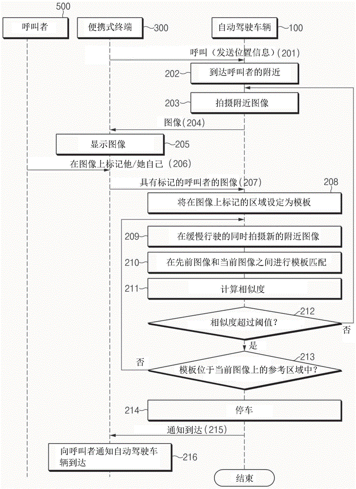
FIG. 2 is a flow chart illustrating a method for caller detection by an autonomous vehicle according to a first form of the present application.
First, the portable terminal 300 calls the autonomous vehicle 100 in response to a request received from the caller 500 (201). In this case, the portable terminal 300 transmits information about the position of the portable terminal 300 to the autonomous vehicle 100. Further, since the portable terminal 300 includes a GPS receiver, the portable terminal 300 can obtain information (GPS position information) about the position of the portable terminal 300.
Thereafter, the autonomous vehicle 100 sets a point corresponding to the received GPS position information from the portable terminal 300 as a destination and reaches the destination by automatic travel (202). In this case, the autonomous vehicle 100 may not reach the location of the caller 500 (e.g., within 2 meters) because the GPS location information has an error. In other words, the autonomous vehicle 100 may come within the vicinity of the caller 500.
Thereafter, the autonomous vehicle 100 takes an image (photograph) of the vicinity of the caller 500 (203). In this case, although it may be considered that the autonomous vehicle 100 captures an image of the front of the autonomous vehicle 100, the autonomous vehicle 100 may capture an image of the side or rear of the autonomous vehicle 100 as needed.
Thereafter, the autonomous vehicle 100 transmits the photographed image to the portable terminal 300(204), and the portable terminal 300 displays the image received therein (205). The caller 500 searches for and marks himself/herself on the image displayed by the portable terminal 300 (206). In this case, when the caller 500 cannot search for himself/herself on the received image, the caller 500 may request to transmit a new image. In this case, the new image may refer to an image newly captured by the slowly-traveling autonomous vehicle 100.
Then, the portable terminal 300 transmits the image on which the caller 500 is marked to the automatic driving vehicle 100 (207). In this case, the image of the caller 500 with the mark is, for example, as shown by reference numerals 410 and 420 of fig. 4A and 4B.
Thereafter, the autonomous vehicle 100 tracks the caller 500 by comparing the image of the caller 500 with the mark with the image newly taken by the slowly moving autonomous vehicle 100.
Hereinafter, a process of tracking the caller 500 through an image taken by the slowly running autonomous vehicle 100 will be described in detail.
The autonomous vehicle 100 sets a mark area on the received image from the portable terminal 300 as a template (208), and periodically captures a new vicinity image while traveling slowly (209). In this case, the process of setting the template may include a process of recognizing the face, hairstyle, or clothes color of the caller in the marked area.
Further, the autonomous vehicle 100 performs template matching between a previous image (the image of the caller with the mark) and a current image (the newly photographed image) (210).
Since template matching is performed at very short time intervals, the similarity representing the matching result exceeds the threshold value except for a special case. In this case, the current image may be an image taken within a short period of time (e.g., 0.5 seconds, 1 second, etc.) after the previous image was taken. Further, the size (R) of the target region on the image subjected to template matching may be determined based on the angle of view and resolution of the camera 111, the speed of the vehicle, the operation period (number of frames/second), or the size of the template. For example, when the operation period is 20 frames/sec, the angle of view of the camera 111 is 100 degrees, the resolution of the camera 111 is 2M, the speed of the vehicle is 15KPH, and the size of the template is 20 pixels, the size of the target region within the image may be determined to be 40 pixels.
Thereafter, the autonomous vehicle 100 calculates the similarity based on the template matching result (211). The process of calculating the similarity may be performed by various well-known techniques.
Thereafter, the autonomous vehicle 100 determines whether the similarity exceeds a threshold (212).
When the similarity does not exceed the threshold as a result of the determination (212), operation 203 is performed. When the similarity exceeds a threshold, it is determined whether the template is located in a reference area on the current image (213).
When the template is not located in the reference area in the determination result 213, operation 209 is performed and the above-described process is repeated. When the template is located in the reference area, the autonomous vehicle 100 is parked (214).
Further, a notification that the autonomous vehicle 100 has reached the position of the caller 500 is transmitted to the portable terminal 300 (215). Then, the portable terminal 300 displays the notification, thereby drawing the attention of the caller 500 (216).
Although the first form of the present application is described as a process related to detecting a caller through template matching, a facial recognition manner may be used based on various facial photographs of a caller that is previously registered. In other words, the autonomous vehicle 100 may periodically take a vicinity image after reaching the vicinity of the caller 500, recognizing the caller's face from the image of the caller with the tag. Then, the autonomous vehicle 100 may track the caller 500 by using the image photographed later. In this case, the resolution of the camera 111 may be selected from High Definition (HD), full high definition, Quad High Definition (QHD), and ultra high definition (UDH) as needed.
FIG. 3 is a flow chart illustrating a method for caller detection by an autonomous vehicle according to a second form of the present application.
First, the portable terminal 300 calls the autonomous vehicle 100 in response to a request received from the caller 500 (301). In this case, the portable terminal 300 transmits information about the position of the portable terminal 300 to the autonomous vehicle 100. Further, since the portable terminal 300 includes a GPS receiver, the portable terminal 300 can obtain information on the position of the portable terminal 300.
Thereafter, the autonomous vehicle 100 sets a point corresponding to the received GPS position information from the portable terminal 300 as a destination and reaches the destination by automatic travel (302). In this case, the autonomous vehicle 100 may not reach the location of the caller 500 (e.g., within 2 meters) because the GPS location information has an error. In other words, the autonomous vehicle 100 may come within the vicinity of the caller 500.
Thereafter, the autonomous vehicle 100 takes a three-dimensional (3D) image (photograph) of the vicinity of the caller 500 (303). The 3D image captured in this manner is, for example, as shown in fig. 4A and 4B. The data of the 3D image includes information on the distance to an object (person) on the image. In this case, although the autonomous vehicle 100 may capture an image of the front of the autonomous vehicle 100, the autonomous vehicle 100 may capture an image of the side or rear of the autonomous vehicle 100 as needed.
Thereafter, the autonomous vehicle 100 transmits the photographed 3D image to the portable terminal 300(304), and the portable terminal 300 displays the 3D image received therein (305). The caller 500 searches for and marks himself/herself from the 3D image displayed by the portable terminal 300 (306). In this case, when the caller 500 cannot search for himself/herself on the received image, the caller 500 may request to transmit a new image. In this case, the new image may refer to an image newly captured by the slowly-traveling autonomous vehicle 100.
Then, the portable terminal 300 transmits the image on which the caller 500 is marked to the autonomous vehicle 100 (307).
Thereafter, the autonomous vehicle 100 extracts a distance from the caller 500 from the 3D image and then moves to the position of the caller 500 (308, 309)
Thereafter, the autonomous vehicle 100 stops after reaching the location of the caller 500 (310). Then, the autonomous vehicle 100 transmits information notifying the portable terminal 300 of the arrival. In this case, the autonomous vehicle 100 may notify the arrival to the portable terminal 300 by using a display or an electronic board mounted on an external portion of the autonomous vehicle 100.
Then, the portable terminal 300 displays the notification to draw the attention of the caller 500 (312).
Although the second form of the present application is described with respect to a manner of obtaining the distance to the caller 500 by using a 3D image photographed by a 3D camera, the distance to the caller 500 may be obtained by using a 2D camera and a 3D LiDAR, a 2D camera and a 2D LiDAR, and a 2D camera and a 2D radar. In this case, a back projection approach may be used to create information about the distance to a target on the image by converting the signal measured by 3D LiDAR, 2D LiDAR or radar to a point in the image.
In this case, although a 3D image is generated by back projection (as shown in fig. 5) since the 3D LiDAR measures a sufficient amount of distance information (high density distance information), in the case of 2D LiDAR or radar, since the distance information is limited, a caller is marked only in an area having the distance information generated by back projection, thereby obtaining a distance from the caller. The image produced in this way is shown in fig. 6.
FIG. 7 is a flow chart illustrating a method for caller detection by an autonomous vehicle according to a third form of the present application.
First, the portable terminal 300 calls the autonomous vehicle 100 in response to a request received from the caller 500 (701). In this case, the portable terminal 300 transmits information about the position of the portable terminal 300 to the autonomous vehicle 100. Further, since the portable terminal 300 includes a GPS receiver, the portable terminal 300 can obtain information on the position of the portable terminal 300.
Thereafter, the autonomous vehicle 100 sets a point corresponding to the received GPS position information from the portable terminal 300 as a destination and reaches the destination by automatic traveling (702). In this case, the autonomous vehicle 100 may not reach the location of the caller 500 (e.g., within 2 meters) because the GPS location information has an error. In other words, the autonomous vehicle 100 may come within the vicinity of the caller 500.
Thereafter, the autonomous vehicle 100 marks its current location on an electronic map around the caller 500. In this case, the autonomous vehicle 100 may mark the current location of the autonomous vehicle 100 by using a vehicle icon. In this case, the vehicle type (e.g., car, van, or truck) and the color of the vehicle icon may be represented identically to the type and color of the autonomous vehicle 100. Further, the electronic map is a detailed map that makes it easy for the user to recognize the location of the autonomous vehicle 100 and the location of the caller 500. Further, the location of the environmental obstacle detected by the autonomous vehicle 100 may be displayed. In this case, an ID may be assigned to the obstacle. The electronic map may be a 2D electronic map, a 3D electronic map, or an Augmented Reality (AR) image.
Thereafter, the electronic map on which the current position of the autonomous vehicle 100 is marked is transmitted to the portable terminal 300 (704). The portable terminal 300 displays the received electronic map (705), and the caller 500 marks the location of the caller 500 on the electronic map displayed by the portable terminal 300 (706).
Thereafter, the portable terminal 300 transmits the electronic map on which the position of the caller 500 is marked to the autonomous vehicle 100 (707).
Thereafter, the autonomous vehicle 100 extracts the distance from the caller 500 from the electronic map and then moves to the location of the caller 500 (708, 709).
Thereafter, the autonomous vehicle 100 stops after reaching the location of the caller 500 (710). Then, the autonomous vehicle 100 transmits information notifying the arrival to the portable terminal 300 (711). In this case, the autonomous vehicle 100 may notify the arrival to the portable terminal 300 by using a display or an electronic board mounted on an external portion of the autonomous vehicle 100.
Then, the portable terminal 300 displays the notification to draw the attention of the caller 500 (712).
FIG. 8 is a block diagram illustrating a computing system implementing a method for caller detection by an autonomous vehicle according to another exemplary form of the present application.
Referring to fig. 8, a method for detecting a caller may be implemented by a computing system. The computing system 1000 may include: at least one processor 1100, a memory (memory)1300, a user interface input device 1400, a user interface output device 1500, a storage 1600, and a network interface 1700, which are connected to each other via a bus 1200.
Accordingly, the operations of a method or algorithm described in connection with the forms disclosed in the specification may be embodied directly in a hardware module, in a software module executed by the processor 1100, or in a combination of the two. A software module may reside on a storage medium (e.g., memory 1300 and/or storage 1600), such as RAM, flash memory, ROM, Erasable Programmable ROM (EPROM), Electrically Erasable Programmable ROM (EEPROM), registers, a hard disk, a removable optical disk, or a compact disk-ROM (CD-ROM). An exemplary storage medium may be coupled to processor 1100. The processor 1100 can read information from, and write information to, the storage medium. In the alternative, the storage medium may be integral to the processor 1100. The integrated processor and the storage medium may reside in an Application Specific Integrated Circuit (ASIC). The ASIC may reside in a user terminal. Alternatively, the integrated processor and the storage medium may reside as separate components in a user terminal.
As described above, according to the present application, the autonomous vehicle closer to the caller transmits an image of the vicinity of the autonomous vehicle to the portable terminal of the caller, thereby causing the caller to specify the caller on the image. Further, the autonomous vehicle automatically travels to the location of the caller based on the image of the caller tag, thereby preventing or avoiding the caller from personally detecting the autonomous vehicle.
Although the present application has been described with reference to exemplary forms, it will be apparent to those skilled in the art that various changes and modifications may be made without departing from the spirit and scope of the application.
Accordingly, the exemplary forms of the present application are not intended to be limiting, but rather are illustrative, and the spirit and scope of the present application is not limited thereto. It should be construed that all technical equivalents to the present application are included in the spirit and scope of the present application.
Claims (19)
Applications Claiming Priority (2)
| Application Number | Priority Date | Filing Date | Title |
|---|---|---|---|
| KR10-2018-0117095 | 2018-10-01 | ||
| KR1020180117095A KR102587085B1 (en) | 2018-10-01 | 2018-10-01 | Method for searching caller of autonomous vehicle |
Publications (2)
| Publication Number | Publication Date |
|---|---|
| CN110972111A true CN110972111A (en) | 2020-04-07 |
| CN110972111B CN110972111B (en) | 2024-04-23 |
Family
ID=69947484
Family Applications (1)
| Application Number | Title | Priority Date | Filing Date |
|---|---|---|---|
| CN201811456907.3A Active CN110972111B (en) | 2018-10-01 | 2018-11-30 | Method for detecting a caller by an autonomous vehicle |
Country Status (3)
| Country | Link |
|---|---|
| US (1) | US20200103918A1 (en) |
| KR (1) | KR102587085B1 (en) |
| CN (1) | CN110972111B (en) |
Families Citing this family (6)
| Publication number | Priority date | Publication date | Assignee | Title |
|---|---|---|---|---|
| DE102019212022B4 (en) * | 2019-08-09 | 2021-03-04 | Volkswagen Aktiengesellschaft | Method and device for determining a parallax problem in sensor data from two sensors |
| DE102019212021B4 (en) * | 2019-08-09 | 2024-02-08 | Volkswagen Aktiengesellschaft | Method and device for detecting a parallax problem in sensor data from two sensors |
| US11491909B2 (en) | 2020-09-16 | 2022-11-08 | Waymo Llc | External facing communications for autonomous vehicles |
| CN114937140B (en) * | 2022-07-25 | 2022-11-04 | 深圳大学 | Large-scale scene-oriented image rendering quality prediction and path planning system |
| KR102851817B1 (en) | 2022-11-22 | 2025-08-28 | 주식회사 에스더블유엠 | Modification method of driving schedule for autonomous vehicle call service |
| JP2024160630A (en) * | 2023-05-01 | 2024-11-14 | トヨタ自動車株式会社 | Vehicle control device and vehicle control method |
Citations (17)
| Publication number | Priority date | Publication date | Assignee | Title |
|---|---|---|---|---|
| JP2003067890A (en) * | 2001-08-22 | 2003-03-07 | Fujitsu Ten Ltd | Vehicle allocation system, vehicle allocation request program and information terminal |
| CN105759295A (en) * | 2014-09-02 | 2016-07-13 | 现代自动车株式会社 | Apparatus And Method For Recognizing Driving Environment For Autonomous Vehicle |
| KR20160119321A (en) * | 2015-04-02 | 2016-10-13 | 김진영 | Method for taxi call service |
| US20170008490A1 (en) * | 2014-04-01 | 2017-01-12 | Mico Latta Inc. | Vehicle and program for vehicle |
| US20170080900A1 (en) * | 2015-09-18 | 2017-03-23 | Ford Global Technologies, Llc | Autonomous vehicle unauthorized passenger or object detection |
| WO2017057053A1 (en) * | 2015-09-30 | 2017-04-06 | ソニー株式会社 | Information processing device, information processing method |
| JP2017136977A (en) * | 2016-02-04 | 2017-08-10 | みこらった株式会社 | Automobile and automobile program |
| CN107351763A (en) * | 2016-05-09 | 2017-11-17 | Lg电子株式会社 | Control device for vehicle |
| CN107369207A (en) * | 2016-05-11 | 2017-11-21 | 百度(美国)有限责任公司 | The system and method that enhancing virtual reality content is provided in automatic driving vehicle |
| US20180025044A1 (en) * | 2016-07-20 | 2018-01-25 | Drone Comply International, Inc. | Unmanned vehicle data correlation, routing, and reporting |
| WO2018018177A1 (en) * | 2016-07-24 | 2018-02-01 | 刘文婷 | Precise passenger identification system for use in driverless car |
| US20180096445A1 (en) * | 2016-09-30 | 2018-04-05 | Lyft, Inc. | Identifying matched requestors and providers |
| US9971348B1 (en) * | 2015-09-29 | 2018-05-15 | Amazon Technologies, Inc. | Passenger profiles for autonomous vehicles |
| CN108121343A (en) * | 2016-11-29 | 2018-06-05 | Lg电子株式会社 | Autonomous land vehicle |
| JP2018100008A (en) * | 2016-12-21 | 2018-06-28 | 矢崎総業株式会社 | Vehicular display device |
| CN108230077A (en) * | 2016-12-21 | 2018-06-29 | 北京嘀嘀无限科技发展有限公司 | The reservation vehicle display methods and device of mobile network appliance |
| US20180194344A1 (en) * | 2016-07-29 | 2018-07-12 | Faraday&Future Inc. | System and method for autonomous vehicle navigation |
Family Cites Families (2)
| Publication number | Priority date | Publication date | Assignee | Title |
|---|---|---|---|---|
| KR101456184B1 (en) * | 2011-09-30 | 2014-11-04 | 성균관대학교산학협력단 | Autonomous vehicle transport control method and apparatus, and autonomous vehicle transport control method and apparatus through remote communication apparatus and remote communication apparatus for autonomous vehicle transport control |
| US10055694B2 (en) * | 2012-08-07 | 2018-08-21 | Hitachi, Ltd. | Use-assisting tool for autonomous mobile device, operation management center, operation system, and autonomous mobile device |
-
2018
- 2018-10-01 KR KR1020180117095A patent/KR102587085B1/en active Active
- 2018-11-20 US US16/196,082 patent/US20200103918A1/en not_active Abandoned
- 2018-11-30 CN CN201811456907.3A patent/CN110972111B/en active Active
Patent Citations (17)
| Publication number | Priority date | Publication date | Assignee | Title |
|---|---|---|---|---|
| JP2003067890A (en) * | 2001-08-22 | 2003-03-07 | Fujitsu Ten Ltd | Vehicle allocation system, vehicle allocation request program and information terminal |
| US20170008490A1 (en) * | 2014-04-01 | 2017-01-12 | Mico Latta Inc. | Vehicle and program for vehicle |
| CN105759295A (en) * | 2014-09-02 | 2016-07-13 | 现代自动车株式会社 | Apparatus And Method For Recognizing Driving Environment For Autonomous Vehicle |
| KR20160119321A (en) * | 2015-04-02 | 2016-10-13 | 김진영 | Method for taxi call service |
| US20170080900A1 (en) * | 2015-09-18 | 2017-03-23 | Ford Global Technologies, Llc | Autonomous vehicle unauthorized passenger or object detection |
| US9971348B1 (en) * | 2015-09-29 | 2018-05-15 | Amazon Technologies, Inc. | Passenger profiles for autonomous vehicles |
| WO2017057053A1 (en) * | 2015-09-30 | 2017-04-06 | ソニー株式会社 | Information processing device, information processing method |
| JP2017136977A (en) * | 2016-02-04 | 2017-08-10 | みこらった株式会社 | Automobile and automobile program |
| CN107351763A (en) * | 2016-05-09 | 2017-11-17 | Lg电子株式会社 | Control device for vehicle |
| CN107369207A (en) * | 2016-05-11 | 2017-11-21 | 百度(美国)有限责任公司 | The system and method that enhancing virtual reality content is provided in automatic driving vehicle |
| US20180025044A1 (en) * | 2016-07-20 | 2018-01-25 | Drone Comply International, Inc. | Unmanned vehicle data correlation, routing, and reporting |
| WO2018018177A1 (en) * | 2016-07-24 | 2018-02-01 | 刘文婷 | Precise passenger identification system for use in driverless car |
| US20180194344A1 (en) * | 2016-07-29 | 2018-07-12 | Faraday&Future Inc. | System and method for autonomous vehicle navigation |
| US20180096445A1 (en) * | 2016-09-30 | 2018-04-05 | Lyft, Inc. | Identifying matched requestors and providers |
| CN108121343A (en) * | 2016-11-29 | 2018-06-05 | Lg电子株式会社 | Autonomous land vehicle |
| JP2018100008A (en) * | 2016-12-21 | 2018-06-28 | 矢崎総業株式会社 | Vehicular display device |
| CN108230077A (en) * | 2016-12-21 | 2018-06-29 | 北京嘀嘀无限科技发展有限公司 | The reservation vehicle display methods and device of mobile network appliance |
Also Published As
| Publication number | Publication date |
|---|---|
| US20200103918A1 (en) | 2020-04-02 |
| KR20200039046A (en) | 2020-04-16 |
| KR102587085B1 (en) | 2023-10-11 |
| CN110972111B (en) | 2024-04-23 |
Similar Documents
| Publication | Publication Date | Title |
|---|---|---|
| CN110972111B (en) | Method for detecting a caller by an autonomous vehicle | |
| CN106794874B (en) | Method and monitoring system for operating an autonomously guided driverless motor vehicle | |
| US20210365696A1 (en) | Vehicle Intelligent Driving Control Method and Device and Storage Medium | |
| CN108399792B (en) | Unmanned vehicle avoidance method and device and electronic equipment | |
| JP2024023319A (en) | Emergency vehicle detection | |
| US10864906B2 (en) | Method of switching vehicle drive mode from automatic drive mode to manual drive mode depending on accuracy of detecting object | |
| CN114973644B (en) | Road information generating device | |
| JP6630521B2 (en) | Danger determination method, danger determination device, danger output device, and danger determination system | |
| CN110869867B (en) | Methods, devices and storage media for validating digital maps of vehicles | |
| JP7233386B2 (en) | Map update device, map update system, and map update method | |
| CN108241851A (en) | Information processing device, information processing method, and program | |
| CN108327719A (en) | The method and device of assisting vehicle travel | |
| CN112581792B (en) | Driving support system, driving support method, and computer-readable storage medium | |
| CN108248602A (en) | Information processing unit, information processing method and program | |
| CN108242182B (en) | Information processing apparatus, information processing method, and recording medium | |
| KR20200043252A (en) | Overlooking image generation system of vehicle and method thereof | |
| CN111144179A (en) | Scene detection device and method | |
| CN115963785A (en) | Method, system, and apparatus for a vehicle and storage medium | |
| CN115050203B (en) | Map generation device and vehicle position recognition device | |
| CN108387238A (en) | Method for localizing more highly automated vehicles in digital maps | |
| CN115320619A (en) | Method for scene interpretation of a vehicle environment | |
| CN114096996A (en) | Method and apparatus for using augmented reality in traffic | |
| JP7449206B2 (en) | Communication control device, vehicle, program, and communication control method | |
| JP2018073275A (en) | Image recognition device | |
| JP2022056153A (en) | Temporary stop detection device, temporary stop detection system, and temporary stop detection program |
Legal Events
| Date | Code | Title | Description |
|---|---|---|---|
| PB01 | Publication | ||
| PB01 | Publication | ||
| SE01 | Entry into force of request for substantive examination | ||
| SE01 | Entry into force of request for substantive examination | ||
| GR01 | Patent grant | ||
| GR01 | Patent grant | ||
| TG01 | Patent term adjustment | ||
| TG01 | Patent term adjustment |