Disclosure of Invention
The invention aims to design automatic rotary riveting double-station equipment for fastening bolts of a clutch cover assembly in a mechanical mode.
The height-adjustable foot margin is fixedly installed below a main body support, a rotating mechanism of a workpiece tray is fixedly installed on the main body support, two vertical guide rods are fixedly installed on one side of the main body support, a middle vertical guide rod is fixedly installed in the middle of a workbench bracket and inserted into a workbench rotating shaft, the two vertical guide rods and the middle vertical guide rod form a triangular support, a middle sliding plate is sleeved in the middle of the triangular support, an upper sliding plate is sleeved at the upper end of the triangular support, a support guide rod is fixedly installed between the middle sliding plate and the upper sliding plate, a screw screwing wrench mechanism is installed by taking the support guide rod as a guide rod, limiting heads are arranged at the top ends of the two vertical guide rods and the middle vertical guide rod, a cylinder body of a pre-compression cylinder is fixedly installed on the limiting heads, and; a manual wrench mechanism is sleeved on the middle vertical guide rod between the middle sliding plate and the upper sliding plate; a workpiece hoisting mechanism is arranged on a main body supporting angle of the workpiece platform corresponding to the preassembled bolt;
a rotating mechanism: the rotary stepping motor is fixed on the main body support, the workbench support is fixed on the main body support, a workbench rotating shaft is arranged in the middle of a workbench support beam through a bearing and driven by the rotary stepping motor, a working platform is fixedly arranged on the workbench rotating shaft, and workpiece platforms are arranged on two sides of the working platform by taking the workbench rotating shaft as the center;
screw spanner mechanism of screwing: the wrench moving mechanism comprises a wrench moving cylinder, a wrench moving guide rod, a wrench moving sliding plate, a wrench moving guide sleeve, a wrench moving sliding chute, a wrench moving cylinder, a wrench moving piston and a wrench moving piston, wherein the wrench moving cylinder is fixed on an upper sliding plate;
manual spanner mechanism: the manual wrench comprises a middle vertical guide rod, a cylinder body of an up-and-down moving cylinder, a small guide rod, two manual wrench sliding sleeves, a manual wrench rotating rod, an extension rod, a small rotating rod and a manual wrench, wherein the middle vertical guide rod is sleeved with the manual wrench guiding sleeves;
the workpiece hoisting mechanism comprises: the bottom end of the lifting upright rod is fixed on the main body support, a lifting rotating sleeve is arranged on the lifting upright rod, the tail end of a lifting cross arm is fixed on the lifting rotating sleeve, a lifting rope hook is arranged on the lifting cross arm, and a winding motor is arranged on the lifting rope.
The invention replaces manual operation, improves the product quality, reduces the labor intensity of operators, improves the product quality, and has simple and convenient operation. The installation pressure plate automatic connection screwing bolt double-station connecting equipment replaces the conventional technological operation process.
Detailed Description
The invention relates to a comprehensive mechanism which mainly comprises a rotating mechanism (used for switching a pre-installed bolt and a fastening bolt workbench back and forth), a screw screwing wrench mechanism (corresponding to the fastening bolt mechanism and fastening the bolt), a manual wrench mechanism (corresponding to the pre-installed bolt mechanism, aligning all components of a clutch and placing the components on the pre-installed workbench, placing the bolt on a bolt hole, simply installing but not fastening), and a workpiece lifting mechanism (used for placing all components of the clutch on the pre-installed workbench).
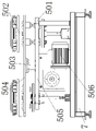
The height-adjustable ground feet 6 are fixedly arranged below the main body support 7, and the height-adjustable ground feet 6 can be adjusted at will and are used for adjusting the balance and stability of the whole mechanism. A rotating mechanism 5 of a workpiece tray 8 is fixedly arranged on a main body support 7, two upright guide rods 3 are fixedly arranged on one side of the main body support 7, the two upright guide rods 3 are two in total, so that the guiding effect and the supporting effect are achieved, an intermediate upright guide rod 4 is fixedly arranged in the middle of a workbench bracket 505, the intermediate upright guide rod 4 is inserted into a workbench rotating shaft 503, the intermediate upright guide rod 4 has the same effect as the two upright guide rods 3, namely the guiding effect and the supporting effect, but is shorter than the two upright guide rods 3, is supported on the workbench bracket 505, although the intermediate upright guide rod 4 is inserted into the workbench rotating shaft 503, the rotation of the workbench rotating shaft 503 is not influenced, the two upright guide rods 3 and the intermediate upright guide rod 4 form a triangular support, a supporting plane of a certificate is formed through the triangular support, a middle sliding plate 13 is sleeved in the middle of the triangular support, an upper sliding plate 2 is sleeved at the upper end of the triangular support, the middle sliding plate 13 and the upper sliding plate 2 can slide on three guide rods of a triangular support, a support guide rod 14 is fixedly arranged between the middle sliding plate 13 and the upper sliding plate 2, the support guide rod 14 ensures that the middle sliding plate 13 and the upper sliding plate 2 slide up and down synchronously, a screw tightening wrench mechanism 12 is arranged by taking the support guide rod 14 as a guide rod, the top ends of the two vertical guide rods 3 and the middle vertical guide rod 4 are provided with limiting heads 15, the limiting heads 15 are used for preventing the upper sliding plate 2 from separating from the top ends of the two vertical guide rods 3 and the middle vertical guide rod 4 when returning upwards, a cylinder body of the pre-compression cylinder 1 is fixedly arranged on the limiting heads 15, and a cylinder plug of the pre-compression cylinder 1 is fixedly connected with the. A manual wrench mechanism 11 is sleeved on the middle vertical guide rod 4 between the middle sliding plate 13 and the upper sliding plate 2. A workpiece hoisting mechanism 10 is arranged on the main body support 7 corner of the workpiece platform corresponding to the pre-installed bolt; the workpiece hoisting mechanism 10 is an auxiliary mechanism, the installation position is not particularly fixed, and the clutch assembly can be conveniently placed on the workbench, generally, only the loose assembly which is not assembled is placed.
The bottom of the middle sliding plate 13 is provided with a pre-pressing head 9 corresponding to a station of the clutch, and the pre-pressing head is used for enabling the listed components of the clutch to reach the station after installation, so that the clutch can be conveniently fastened by using a clutch bolt.
A rotating mechanism 5: the rotary stepping motor 506 is fixed on the main body support 7, the workbench support 505 is fixed on the main body support 7, the middle of the cross beam of the workbench support 505 is provided with a workbench rotating shaft 503 through a bearing, the workbench rotating shaft 503 is driven by the rotary stepping motor 506, the workbench rotating shaft 503 is fixedly provided with a workbench 504, and two sides of the workbench 504 which take the workbench rotating shaft 503 as the center are provided with workpiece platforms 502; the operation of the rotary stepper motor 506 may cause the pre-assembled bolt to move horizontally and the fastening bolt to move back and forth to exchange positions, but in order to ensure the accuracy of the positions, a positioning device 501 may be installed at the bottom of the two platforms, which ensures that the two platforms always correspond to the positions of the upper mechanisms.
Screw tightening wrench mechanism 12: the screw tightening wrench mechanism 12 is a mechanism for tightening all the final bolts of the clutch, and corresponds to the lower fastening bolt working platform, and after the mechanism is finished, the whole clutch is a complete clutch which can be used. The cylinder body of the wrench moving cylinder 1201 is fixed on the upper sliding plate 2, the cylinder plug of the wrench moving cylinder 1201 is fixedly connected with the wrench moving plate 1203, two sides of the wrench moving plate 1203 are sleeved on the support guide rod 14 through wrench moving guide sleeves 1207, a rotating wrench motor 1202 is installed on the wrench moving plate 1203 through an adjusting fastening bolt 1206 and an adjusting fastening sliding chute 1205 which are matched with each other, and a wrench 1204 is installed on a motor shaft of the rotating wrench motor 1202; the up-and-down movement of the mechanism is completed by guiding along the support guide rod 14, the wrench moves the air cylinder 1201 to solve the up-and-down movement, and the wrench motor 1202 is rotated to complete the fastening work of the clutch fastening bolt.
Manual wrench mechanism 11: the mechanism is a corresponding pre-installed bolt workbench, only the clutch bolt on the workbench is simply placed in the bolt hole, and under simple fastening, the bolt is not completely stressed, so that the clutch cannot be fastened completely. The manual spanner guide sleeve 1105 is sleeved on the middle vertical guide rod 4, two manual spanner guide sleeves 1105 are arranged in practical application for stability, and are completely fixed on the middle vertical guide rod 4 in the using process, and the height can be adjusted by loosening at any time, and in addition, the two manual spanner guide sleeves 1105 are also convenient for installing the small guide rod 1107. The cylinder body of the up-down moving cylinder 1101 is fixed outside the manual wrench guide sleeve 1105, a small guide rod 1107 is installed between the two manual wrench guide sleeves 1105, two manual wrench sliding sleeves 1106 clamp the manual wrench rotating rod 1102 and are sleeved on the small guide rod 1107 at the same time, the cylinder plug of the up-down moving cylinder 1101 is fixedly connected with the manual wrench sliding sleeves 1106 through a connecting piece, the other end of the manual wrench rotating rod 1102 is connected with a manual wrench rotating head 1103 in a shaft mode, an extension rod 1108 is installed on the manual wrench rotating head 1103, the bottom end of the extension rod 1108 is connected with a small rotating rod 1109 in a shaft mode, and a manual wrench 1104 is installed on the small rotating rod 110; the up-down moving cylinder 1101 controls the up-down moving position of the whole manipulator-like hand pre-assembled bolt, which is manually completed, and after the bolt is placed at the mounting position of the clutch, simple bolt fastening is performed, but fastening is not performed.
Workpiece hoisting mechanism 10: the bottom end of a lifting upright rod 1001 is fixed on a main body support 7, a lifting rotary sleeve 1002 is arranged on the lifting upright rod 1001, the tail end of a lifting cross arm 1003 is fixed on the lifting rotary sleeve 1002, a lifting rope hook 1104 is arranged on the lifting cross arm 1003, and a winding motor 1005 is arranged on the lifting rope 1006.
The operation process of the invention is as follows:
firstly, using a hoisting mechanism to sequentially place each component of a clutch on a pre-installation bolt workbench, then manually placing a bolt corresponding to a bolt hole of the clutch by a worker, and making a simple hanging buckle, then starting a rotating motor to rotate the pre-installation workbench to an installation station, at the moment, converting the pre-installation bolt workbench into an installation bolt workbench which is correspondingly arranged below a screw tightening wrench mechanism, then pre-tightening a cylinder 1 to work, moving the whole middle sliding plate 13, an upper sliding plate 2 and other mechanisms downwards along two vertical guide rods 3, firstly contacting a pre-tightening head 9 with the pre-tightening clutch, then continuing to extrude until each component in the clutch reaches a required station, keeping the state and stopping the pre-tightening cylinder 1 to work, namely starting a motor of the screw tightening wrench mechanism 12 to draw the whole wrench mechanism close the bolt on the clutch, after a wrench on the screw tightening wrench mechanism 12 contacts a bolt on the clutch, the rotating wrench motor 1202 works to completely tighten the bolt, after all the bolts are tightened, the up-and-down moving cylinder of the screw tightening wrench mechanism 12 is started to lift the mechanism, after returning, the pre-pressing cylinder 1 is started to work to drive the middle sliding plate 13 and the upper sliding plate 2 to move upwards and return to the starting position, the pre-pressing head 9 is separated from the contact with the clutch, the fastening and installation of the clutch are completed, the workbench is moved away, at this time, the other workbench also completes the pre-installation process of the clutch assembly, the clutch assembly is rotated to continue to be tightened, and the operation is repeated in sequence.