CN110954817A - Solid-state test platform and method for intelligent phase-change switch function test - Google Patents
Solid-state test platform and method for intelligent phase-change switch function test Download PDFInfo
- Publication number
- CN110954817A CN110954817A CN201911271458.XA CN201911271458A CN110954817A CN 110954817 A CN110954817 A CN 110954817A CN 201911271458 A CN201911271458 A CN 201911271458A CN 110954817 A CN110954817 A CN 110954817A
- Authority
- CN
- China
- Prior art keywords
- module
- capacitor
- phase
- intelligent
- change switch
- Prior art date
- Legal status (The legal status is an assumption and is not a legal conclusion. Google has not performed a legal analysis and makes no representation as to the accuracy of the status listed.)
- Pending
Links
- 238000012360 testing method Methods 0.000 title claims abstract description 64
- 238000000034 method Methods 0.000 title abstract description 8
- 239000003990 capacitor Substances 0.000 claims abstract description 43
- 230000008859 change Effects 0.000 claims abstract description 21
- 238000001914 filtration Methods 0.000 claims abstract description 5
- 238000009499 grossing Methods 0.000 claims abstract description 5
- 238000005070 sampling Methods 0.000 claims description 17
- 238000012795 verification Methods 0.000 claims description 4
- 238000010276 construction Methods 0.000 claims description 3
- 238000010586 diagram Methods 0.000 description 15
- 238000001514 detection method Methods 0.000 description 3
- 230000007547 defect Effects 0.000 description 2
- 230000009286 beneficial effect Effects 0.000 description 1
- 230000005540 biological transmission Effects 0.000 description 1
- 238000013461 design Methods 0.000 description 1
- 238000012938 design process Methods 0.000 description 1
- 230000010354 integration Effects 0.000 description 1
- 239000000463 material Substances 0.000 description 1
- 238000012986 modification Methods 0.000 description 1
- 230000004048 modification Effects 0.000 description 1
- 230000001052 transient effect Effects 0.000 description 1
Images


Classifications
-
- G—PHYSICS
- G01—MEASURING; TESTING
- G01R—MEASURING ELECTRIC VARIABLES; MEASURING MAGNETIC VARIABLES
- G01R31/00—Arrangements for testing electric properties; Arrangements for locating electric faults; Arrangements for electrical testing characterised by what is being tested not provided for elsewhere
- G01R31/327—Testing of circuit interrupters, switches or circuit-breakers
-
- H—ELECTRICITY
- H02—GENERATION; CONVERSION OR DISTRIBUTION OF ELECTRIC POWER
- H02J—CIRCUIT ARRANGEMENTS OR SYSTEMS FOR SUPPLYING OR DISTRIBUTING ELECTRIC POWER; SYSTEMS FOR STORING ELECTRIC ENERGY
- H02J3/00—Circuit arrangements for AC mains or AC distribution networks
- H02J3/26—Arrangements for eliminating or reducing asymmetry in polyphase networks
-
- G—PHYSICS
- G01—MEASURING; TESTING
- G01R—MEASURING ELECTRIC VARIABLES; MEASURING MAGNETIC VARIABLES
- G01R31/00—Arrangements for testing electric properties; Arrangements for locating electric faults; Arrangements for electrical testing characterised by what is being tested not provided for elsewhere
- G01R31/327—Testing of circuit interrupters, switches or circuit-breakers
- G01R31/3271—Testing of circuit interrupters, switches or circuit-breakers of high voltage or medium voltage devices
- G01R31/3275—Fault detection or status indication
-
- G—PHYSICS
- G01—MEASURING; TESTING
- G01R—MEASURING ELECTRIC VARIABLES; MEASURING MAGNETIC VARIABLES
- G01R31/00—Arrangements for testing electric properties; Arrangements for locating electric faults; Arrangements for electrical testing characterised by what is being tested not provided for elsewhere
- G01R31/327—Testing of circuit interrupters, switches or circuit-breakers
- G01R31/3277—Testing of circuit interrupters, switches or circuit-breakers of low voltage devices, e.g. domestic or industrial devices, such as motor protections, relays, rotation switches
-
- Y—GENERAL TAGGING OF NEW TECHNOLOGICAL DEVELOPMENTS; GENERAL TAGGING OF CROSS-SECTIONAL TECHNOLOGIES SPANNING OVER SEVERAL SECTIONS OF THE IPC; TECHNICAL SUBJECTS COVERED BY FORMER USPC CROSS-REFERENCE ART COLLECTIONS [XRACs] AND DIGESTS
- Y02—TECHNOLOGIES OR APPLICATIONS FOR MITIGATION OR ADAPTATION AGAINST CLIMATE CHANGE
- Y02E—REDUCTION OF GREENHOUSE GAS [GHG] EMISSIONS, RELATED TO ENERGY GENERATION, TRANSMISSION OR DISTRIBUTION
- Y02E40/00—Technologies for an efficient electrical power generation, transmission or distribution
- Y02E40/50—Arrangements for eliminating or reducing asymmetry in polyphase networks
Landscapes
- Physics & Mathematics (AREA)
- General Physics & Mathematics (AREA)
- Engineering & Computer Science (AREA)
- Power Engineering (AREA)
- Testing Electric Properties And Detecting Electric Faults (AREA)
- Ac-Ac Conversion (AREA)
Abstract
The invention relates to a solid-state test platform and a method for intelligent commutation switch function test, wherein the test platform comprises a main controller, a module I, a module II and a capacitor C; the main controller is respectively connected with the module I and the module II and is used for controlling the work of the module I and the module II; one end of the module I is connected with the output end of the transformer; one end of the module II is connected with the direct current output end of the intelligent phase change switch; the other end of the module I and the other end of the module II are connected with a capacitor C, and the module I, the module II and the capacitor C are connected in parallel; the module I is used for feeding back redundant energy on the capacitor C to the power distribution network; the module II is used for controlling the magnitude and direction of current flowing through the intelligent phase change switch; the capacitor C is used for energy support, filtering and smoothing. The invention can simulate all unbalanced operation conditions, and the simulated unbalanced power is fed back to the power grid through the test platform in a balanced manner, so that the test under the state without power consumption is realized, and meanwhile, the influence on the main power grid is avoided.
Description
Technical Field
The invention belongs to the technical field of equipment detection, and particularly relates to an extensible low-loss solid-state test platform for intelligent commutation switch function test and a control method thereof.
Background
At present, a function test platform of the intelligent phase change switch can be tested only by accessing an active load, and the problem of active loss exists; and after the loads are connected, the active power and the reactive power of each phase of load can not be adjusted at will, the unbalance degree can not be adjusted, and the loads can not be switched seamlessly and transiently for many times. For example, the problems exist in the patent of intelligent detection device of the phase change switch. Therefore, how to overcome the defects of the prior art is a problem to be solved urgently in the technical field of equipment detection at present.
Disclosure of Invention
In order to overcome the defects that the existing intelligent phase-change switch function test platform cannot realize the functions of randomly adjusting the active power and the reactive power of each phase load, cannot adjust the unbalance degree, cannot perform multiple seamless transient switching loads and the like, the invention provides a solid-state test platform for intelligent phase-change switch function test and a control method thereof.
In order to achieve the purpose, the technical scheme adopted by the invention is as follows:
the solid-state test platform for the function test of the intelligent phase-change switch is characterized by comprising a main controller, a module I, a module II and a capacitor C;
the main controller is respectively connected with the module I and the module II and is used for controlling the work of the module I and the module II;
one end of the module I is connected with the output end of the transformer;
one end of the module II is connected with the direct current output end of the intelligent phase change switch;
the other end of the module I and the other end of the module II are connected with a capacitor C, and the module I, the module II and the capacitor C are connected in parallel;
the module I is used for feeding back redundant energy on the capacitor C to the power distribution network;
the module II is used for controlling the magnitude and direction of current flowing through the intelligent phase change switch;
the capacitor C is used for energy support, filtering and smoothing.
Further, it is preferable that there are a plurality of modules ii.
Further, preferably, the module i comprises an inverter and an LC filter, which are composed of eight switching tubes; and the module I carries out inversion control on the power absorbed by the module II, and the power is filtered by the LC filter to remove high-frequency harmonics and then is transmitted back to the power distribution network.
Further, preferably, the module II comprises a single-phase H-bridge and a filter inductor LN(ii) a Filter inductance LNAnd after the harmonic wave is filtered out from the power absorbed by the module II, the power is rectified and controlled by a single-phase H bridge and then is transmitted to a direct-current capacitor C.
Further, the preferred still includes sampling module, sampling module links to each other with main control unit, sampling module be used for gathering electric wire netting three-phase voltage, electric capacity C's voltage, module I's output current, module II's input current, later return the data of gathering to main control unit, main control unit is through carrying out rectification control and contravariant control back, the switch tube work in control module I, module II.
The invention also provides a solid-state testing method for the intelligent commutation switch function test, which adopts the solid-state testing platform for the intelligent commutation switch function test and comprises the following steps:
step 1: setting active and reactive values to be absorbed by each module II in the main controller, and transmitting the active and reactive values to each corresponding module II;
step 2: the sampling module collects physical quantities, namely three-phase voltage of a power grid, voltage of a capacitor C, output current of a module I and input current of a module II, and transmits the relevant physical quantities to the module I and the module II;
and step 3: the module II carries out rectification control according to the physical quantity, the active value and the passive value sent by the lower main controller, and absorbs and transmits the electric energy to the direct current capacitor C;
and 4, step 4: the module I judges the working state at the moment according to the voltage value of the direct current capacitor C sent by the main controller, then carries out inversion control, and feeds back redundant energy on the direct current capacitor C to the main power grid;
and 5: and at the moment, the construction of the unbalanced operation condition of the solid-state test platform is completed, and then the function of the tested intelligent phase-change switch is started for verification. The function verification of the subsequent phase change switch is automatically carried out by a switch manufacturer according to the self requirement. Verifying the content includes, but is not limited to, verifying whether the commutation switch is capable of performing a legitimate commutation.
The invention mainly discloses a test platform, which provides a test environment for an intelligent phase change switch developed by a manufacturer, and how to verify the function of the phase change switch is out of the protection scope of the patent.
Compared with the prior art, the invention has the beneficial effects that:
1. the invention can change the simulated power in real time and randomly through the single-phase H bridge, and can save more than 90% of the platform building time compared with the prior art without a complex external circuit;
2. compared with the prior art, the test loss can be obviously reduced, and the active loss can be reduced by more than 90% because the energy is fed back to the power grid under the same analog power. (ii) a
3. Compared with the prior art, the invention can simultaneously carry out tests on a large number of intelligent phase change switches (N >3), and the test efficiency can be improved by more than 80%.
4. Compared with the prior art, the intelligent platform can completely realize intelligent operation after the platform is built, and an additional load switch and an auxiliary circuit are not needed, so that the system structure is greatly simplified.
5. The structure provided by the invention can be subjected to modular design and integration, and compared with the prior art, the overall volume can be reduced by more than 40%.
Drawings
FIG. 1 is an overall structure diagram of a solid-state testing platform for testing the functions of an intelligent phase-change switch according to the present invention;
FIG. 2 is a schematic diagram of an intelligent phase-change switch;
FIG. 3 is a partial schematic view of FIG. 1;
FIG. 4 is a block diagram of module I;
FIG. 5 is a block diagram of block II;
FIG. 6 is an overall control block diagram of the solid-state testing platform for testing the functions of the intelligent commutation switch according to the invention;
FIG. 7 is a block diagram and a control schematic diagram of the module I;
FIG. 8 is a block diagram and a control schematic diagram of the module II;
FIG. 9 is a solid-state test platform equivalent circuit model for intelligent commutation switch function test according to the present invention;
wherein, 1, a main controller; 2. a module I; 3. a module II; 4. a capacitor C; 5. an intelligent phase-change switch; 6. a transformer; 7. and a sampling module.
Detailed Description
The present invention will be described in further detail with reference to examples.
It will be appreciated by those skilled in the art that the following examples are illustrative of the invention only and should not be taken as limiting the scope of the invention. The examples do not specify particular techniques or conditions, and are performed according to the techniques or conditions described in the literature in the art or according to the product specifications. The materials or equipment used are not indicated by manufacturers, and all are conventional products available by purchase.
As shown in fig. 1 and fig. 6, the solid-state testing platform for testing functions of the intelligent phase-change switch includes a main controller 1, a module i 2, a module ii 3, and a capacitor C4;
the main controller 1 is respectively connected with the module I2 and the module II 3 and is used for controlling the work of the module I2 and the module II 3;
one end of the module I2 is connected with the output end of the transformer 6;
one end of the module II 3 is connected with the direct current output end of the intelligent phase change switch 5;
the other end of the module I2 and the other end of the module II 3 are connected with a capacitor C4, and the module I2, the module II 3 and the capacitor C4 are connected in parallel;
the module I2 is used for feeding back redundant energy on the capacitor C4 to the distribution network;
the module II 3 is used for controlling the magnitude and direction of current flowing through the intelligent phase change switch 5;
the capacitor C4 is used for energy support, filtering and smoothing.
There are a plurality of modules II 3.
The module I2 comprises a converter and an LC filter, wherein the converter and the LC filter are composed of eight switching tubes; and the module I carries out inversion control on the power absorbed by the module II 3, and the power is filtered by the LC filter to remove high-frequency harmonics and then is transmitted back to the power distribution network.
The module II 3 comprises a single-phase H bridge and a filter inductor LN(ii) a Filter inductance LNAnd after the harmonic wave is filtered out from the power absorbed by the module II 3, the power is rectified and controlled by a single-phase H bridge and then is transmitted to a direct-current capacitor C.
Still include sampling module 7, sampling module 7 links to each other with main control unit 1, sampling module be used for gathering electric wire netting three-phase voltage, electric capacity C's voltage, module I's output current, module II's input current, later return the data of gathering to main control unit 1, main control unit 1 is through carrying out rectification control and contravariant control back, the switch tube work in control module I2, the module II 3.
A solid-state testing method for testing functions of an intelligent phase-change switch adopts the solid-state testing platform for testing functions of the intelligent phase-change switch, and comprises the following steps:
step 1: setting active and reactive values to be absorbed by each module II in the main controller, and transmitting the active and reactive values to each corresponding module II;
step 2: the sampling module collects physical quantities, namely three-phase voltage of a power grid, voltage of a capacitor C, output current of a module I and input current of a module II, and transmits the relevant physical quantities to the module I and the module II;
and step 3: the module II carries out rectification control according to the physical quantity, the active value and the passive value sent by the lower main controller, and absorbs and transmits the electric energy to the direct current capacitor C;
and 4, step 4: the module I judges the working state at the moment according to the voltage value of the direct current capacitor C sent by the main controller, then carries out inversion control, and feeds back redundant energy on the direct current capacitor C to the main power grid;
and 5: and at the moment, the construction of the unbalanced operation condition of the solid-state test platform is completed, and then the function of the tested intelligent phase-change switch is started for verification.
The integral structure of the solid-state test platform for the function test of the intelligent phase-change switch is shown in figure 1. In fig. 1, the intelligent phase-change switches are terminals 1 to N, and neither the intelligent master switch nor the intelligent phase-change switch is a structure of the test platform of the present invention and is taken as a whole to be tested.
The intelligent master control switch is used as a host, and the intelligent phase change switch is used as a slave. The intelligent main control switch mainly comprises a current terminal, a voltage terminal and a function terminal, and partial function terminals are reserved in the design process, so that the product upgrading and the expansion of other functions in the later period are facilitated. The intelligent phase-change switch mainly comprises a three-phase input terminal and a single-phase output terminal, wherein 1, 2 and 3 are ABC three-phase input ends, 4 is N-phase input, 5 is a live wire, 6 is a zero wire, and the structural schematic diagram is shown in figure 2. After the intelligent phase change switch receives the command of the intelligent master switch, the internal part of the intelligent phase change switch switches and connects the 5 ports among the 1 port, the 2 port and the 3 port according to the command requirement, thereby realizing the purpose of phase change.
As shown in fig. 3, the module includes a module i and a module ii, and the two types of modules share a dc capacitor C. The module I is connected with the capacitor C and the power grid and is mainly used for feeding back redundant energy on the capacitor C to the power grid; the module II is connected with the capacitor C and the tested intelligent phase change switch and can control the magnitude and direction of current flowing through the intelligent phase change switch; the capacitor C mainly functions as energy support, filtering and smoothing.
The structure of the module I is shown in figure 4 and comprises: a converter consisting of eight switching tubes and an LC filter. The converter mainly achieves the purpose of transmitting the power absorbed by the modules II at all levels back to the power distribution network through controlling the switch tube; the LC filter is designed to filter out high frequency harmonics, making the output current closer to a sine wave.
The structure of the module II is shown in FIG. 5, and comprises: single-phase H-bridge and filter inductor LN. The single-phase H bridge controls the absorbed power;filter inductance LNMainly to filter out harmonics.
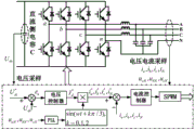
The overall control block diagram of the solid-state test platform for the intelligent commutation switch function test is shown in fig. 6. The structure diagram and the control schematic diagram of the module I are shown in FIG. 7, and the amplitude of the command current is obtained through a voltage controller after the difference is made between the actual value of the direct current voltage obtained by sampling the direct current voltage and the reference value; the method comprises the steps that an alternating voltage value obtained through alternating voltage sampling, namely the voltage of a power distribution network, is subjected to a phase locking link of a PLL (phase locked loop) to obtain the phase of the alternating voltage; the instantaneous value of the reference current can be obtained by utilizing the amplitude and the phase of the obtained reference current, and after the instantaneous value of the reference current is different from the sampled actual value, a modulation signal is obtained through a current controller, and control signals of eight switching tubes of the converter are obtained through Sine Pulse Width Modulation (SPWM), wherein a voltage and current controller usually adopts a PI controller, and the purpose of adopting the control mode is mainly to maintain the stability of the voltage of a direct current side capacitor, and simultaneously, the energy absorbed by a module II is transmitted back to a power distribution network in a three-phase symmetrical mode.
The structure diagram and the control schematic diagram of the module II are shown in FIG. 8. The reference power n is given according to the requirement of the main controller, the voltage is basically kept unchanged due to the voltage support of the power distribution network, and after the voltage signal of the alternating current side is collected through the voltage transformer, the reference current of the single-phase H bridge can be converted under the condition of given power, and meanwhile, the output current phase tracking is guaranteed. After sampling the output current filtered by the single-phase H-bridge, performing current tracking control on the reference current and the sampling current, generally adopting a PI controller to control, obtaining a modulation signal after the difference between the two is processed by the PI controller, and obtaining four switching tube control signals in the single-phase H-bridge after the modulation signal is subjected to Sinusoidal Pulse Width Modulation (SPWM), namely realizing the tracking control on the reference power n and achieving the purpose of simulating the load.
4. Deducing the advantages of the patent of the invention by reasoning
The equivalent circuit model of the solid-state test platform for the intelligent commutation switch function test is shown in fig. 9. Wherein, Is (a,b,c)Representing three-phase currents of a, b and c on the network side; i isCT (a,b,c)The three-phase current a, b and c collected by the intelligent master switch through the current transformer is represented; i isL (a,b,c)Representing three-phase current on the load side; i is1 (a,b,c)Representing three-phase current output by the three-phase four-wire system converter; n isa/b/cRespectively representing the number of the phase-only switches connected with the a/b/c phase and the number of single-phase H bridges; i is2 (a,b,c)Respectively representing the total input current of a single-phase H bridge which is independently connected with the a, b and c three phases through an intelligent phase-change switch; p1 (a,b,c)Representing the output power of each phase of the three-phase four-wire system converter; p2 (a,b,c)Respectively representing the total power input by each phase of the intelligent phase-change switch.
According to the circuit structure and the energy transmission path of the power electronic platform, an equation and an inequality (1) can be obtained:
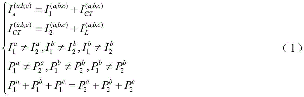
according to the fifth equation in the formula (1), under the condition of neglecting the loss of the electronic device, the total input power and the total output power of the power electronic platform test platform are equal, the intelligent phase-change switch test under the zero-power loss is realized, and the electric energy loss is greatly reduced.
The foregoing shows and describes the general principles, essential features, and advantages of the invention. It will be understood by those skilled in the art that the present invention is not limited to the embodiments described above, which are described in the specification and illustrated only to illustrate the principle of the present invention, but that various changes and modifications may be made therein without departing from the spirit and scope of the present invention, which fall within the scope of the invention as claimed. The scope of the invention is defined by the appended claims and equivalents thereof.
Claims (6)
1. The solid-state test platform for the function test of the intelligent phase-change switch is characterized by comprising a main controller (1), a module I (2), a module II (3) and a capacitor C (4);
the main controller (1) is respectively connected with the module I (2) and the module II (3) and is used for controlling the module I (2) and the module II (3) to work;
one end of the module I (2) is connected with the output end of the transformer (6);
one end of the module II (3) is connected with the direct current output end of the intelligent phase change switch (5);
the other end of the module I (2) and the other end of the module II (3) are connected with a capacitor C (4), and the module I (2), the module II (3) and the capacitor C (4) are connected in parallel;
the module I (2) is used for feeding back redundant energy on the capacitor C (4) to the power distribution network;
the module II (3) is used for controlling the magnitude and direction of current flowing through the intelligent phase change switch (5);
the capacitor C (4) is used for energy support, filtering and smoothing.
2. The solid-state test platform for testing the functions of the intelligent phase-change switch according to claim 1, wherein the number of the modules II (3) is multiple.
3. The solid-state test platform for testing the functions of the intelligent phase-change switches according to claim 1, wherein the module I (2) comprises a converter and an LC filter, wherein the converter consists of eight switching tubes; and the module I carries out inversion control on the power absorbed by the module II (3), and the power is filtered by the LC filter to remove high-frequency harmonics and then is transmitted back to the power distribution network.
4. The solid-state test platform for intelligent commutation switch function test according to claim 1, wherein the module II (3) comprises a single-phase H-bridge and a filter inductorL N (ii) a Filter inductorL N And after the power absorbed by the module II (3) is filtered to remove harmonics, the power is rectified and controlled by a single-phase H bridge and then is transmitted to a direct-current capacitor C.
5. The solid-state test platform for intelligent commutation switch function test as claimed in claim 1, further comprising a sampling module (7), wherein the sampling module (7) is connected with the main controller (1), the sampling module is used for collecting three-phase voltage of a power grid, voltage of a capacitor C, output current of a module I and input current of a module II, collected data are transmitted back to the main controller (1), and after the main controller (1) performs rectification control and inversion control, switching tubes in the module I (2) and the module II (3) are controlled to work.
6. A solid-state testing method for testing functions of an intelligent phase-change switch, which adopts the solid-state testing platform for testing functions of the intelligent phase-change switch, as claimed in any one of claims 1 to 5, is characterized by comprising the following steps:
step 1: setting active and reactive values to be absorbed by each module II in the main controller, and transmitting the active and reactive values to each corresponding module II;
step 2: the sampling module collects physical quantities, namely three-phase voltage of a power grid, voltage of a capacitor C, output current of a module I and input current of a module II, and transmits the relevant physical quantities to the module I and the module II;
and step 3: the module II carries out rectification control according to the physical quantity, the active value and the passive value sent by the lower main controller, and absorbs and transmits the electric energy to the direct current capacitor C;
and 4, step 4: the module I judges the working state at the moment according to the voltage value of the direct current capacitor C sent by the main controller, then carries out inversion control, and feeds back redundant energy on the direct current capacitor C to the main power grid;
and 5: and at the moment, the construction of the unbalanced operation condition of the solid-state test platform is completed, and then the function of the tested intelligent phase-change switch is started for verification.
Priority Applications (3)
| Application Number | Priority Date | Filing Date | Title |
|---|---|---|---|
| CN201911271458.XA CN110954817A (en) | 2019-12-12 | 2019-12-12 | Solid-state test platform and method for intelligent phase-change switch function test |
| PCT/CN2020/128815 WO2021115023A1 (en) | 2019-12-12 | 2020-11-13 | Solid-state test platform and method oriented to function test for smart phase-change switch |
| US17/422,727 US11366163B2 (en) | 2019-12-12 | 2020-11-13 | Solid testing platform and method for function testing of intelligent phase-change switch |
Applications Claiming Priority (1)
| Application Number | Priority Date | Filing Date | Title |
|---|---|---|---|
| CN201911271458.XA CN110954817A (en) | 2019-12-12 | 2019-12-12 | Solid-state test platform and method for intelligent phase-change switch function test |
Publications (1)
| Publication Number | Publication Date |
|---|---|
| CN110954817A true CN110954817A (en) | 2020-04-03 |
Family
ID=69981107
Family Applications (1)
| Application Number | Title | Priority Date | Filing Date |
|---|---|---|---|
| CN201911271458.XA Pending CN110954817A (en) | 2019-12-12 | 2019-12-12 | Solid-state test platform and method for intelligent phase-change switch function test |
Country Status (3)
| Country | Link |
|---|---|
| US (1) | US11366163B2 (en) |
| CN (1) | CN110954817A (en) |
| WO (1) | WO2021115023A1 (en) |
Cited By (2)
| Publication number | Priority date | Publication date | Assignee | Title |
|---|---|---|---|---|
| CN112213075A (en) * | 2020-09-24 | 2021-01-12 | 云南电网有限责任公司昆明供电局 | Multifunctional tail fiber testing device and using method |
| WO2021115023A1 (en) * | 2019-12-12 | 2021-06-17 | 云南电网有限责任公司临沧供电局 | Solid-state test platform and method oriented to function test for smart phase-change switch |
Citations (2)
| Publication number | Priority date | Publication date | Assignee | Title |
|---|---|---|---|---|
| CN108427071A (en) * | 2018-05-15 | 2018-08-21 | 国网福建省电力有限公司电力科学研究院 | A kind of phase-change switch intelligent detection device and method |
| CN108574305A (en) * | 2018-05-22 | 2018-09-25 | 国电南京自动化股份有限公司 | Cascaded high-voltage frequency converter power cell load platform with feedback function |
Family Cites Families (12)
| Publication number | Priority date | Publication date | Assignee | Title |
|---|---|---|---|---|
| DE4202655A1 (en) * | 1992-01-31 | 1993-08-05 | Peter Schieritz | Test instrument for single and three=phase equipment - has phase selection switching, earth continuity and conductivity verification and phase sequence indication |
| JP3863123B2 (en) | 2003-04-04 | 2006-12-27 | 三菱電機株式会社 | 3-phase circuit load unbalance elimination control system |
| DE102005028270A1 (en) * | 2005-06-14 | 2006-12-28 | Siemens Ag | Lossless high current testing system |
| US7660135B2 (en) * | 2007-05-23 | 2010-02-09 | Hamilton Sundstrand Corporation | Universal AC high power inveter with galvanic isolation for linear and non-linear loads |
| CN100533166C (en) * | 2007-06-29 | 2009-08-26 | 株洲南车时代电气股份有限公司 | A test circuit for a converter |
| EP2313966B1 (en) * | 2008-07-30 | 2019-07-03 | Rolls-Royce Corporation | Electrical power system with high-density pulse width modulated (pwm) rectifier |
| CN102354982B (en) * | 2011-09-29 | 2013-10-16 | 日立电梯(中国)有限公司 | Energy feedback elevator system |
| CN106291207B (en) * | 2016-08-31 | 2019-02-01 | 许继电气股份有限公司 | A chain SVG module testing system, platform and method |
| CN108152729B (en) * | 2018-01-12 | 2025-08-15 | 江苏南瑞泰事达电气有限公司 | Detection device and method for three-phase current unbalance adjustment device |
| CN208767798U (en) * | 2018-10-31 | 2019-04-19 | 山东康润电气股份有限公司 | Dynamic SVG module and phase-change switch mixed type three-phase imbalance governing system |
| CN110176890B (en) * | 2019-05-06 | 2020-10-27 | 浙江大学 | Braking torque control method of brushless DC motor based on non-inductive hybrid energy storage system |
| CN110954817A (en) * | 2019-12-12 | 2020-04-03 | 云南电网有限责任公司临沧供电局 | Solid-state test platform and method for intelligent phase-change switch function test |
-
2019
- 2019-12-12 CN CN201911271458.XA patent/CN110954817A/en active Pending
-
2020
- 2020-11-13 WO PCT/CN2020/128815 patent/WO2021115023A1/en not_active Ceased
- 2020-11-13 US US17/422,727 patent/US11366163B2/en active Active
Patent Citations (2)
| Publication number | Priority date | Publication date | Assignee | Title |
|---|---|---|---|---|
| CN108427071A (en) * | 2018-05-15 | 2018-08-21 | 国网福建省电力有限公司电力科学研究院 | A kind of phase-change switch intelligent detection device and method |
| CN108574305A (en) * | 2018-05-22 | 2018-09-25 | 国电南京自动化股份有限公司 | Cascaded high-voltage frequency converter power cell load platform with feedback function |
Cited By (3)
| Publication number | Priority date | Publication date | Assignee | Title |
|---|---|---|---|---|
| WO2021115023A1 (en) * | 2019-12-12 | 2021-06-17 | 云南电网有限责任公司临沧供电局 | Solid-state test platform and method oriented to function test for smart phase-change switch |
| US11366163B2 (en) | 2019-12-12 | 2022-06-21 | Lincang Power Supply Bureau Yunnan Power Grid Co., Ltd. | Solid testing platform and method for function testing of intelligent phase-change switch |
| CN112213075A (en) * | 2020-09-24 | 2021-01-12 | 云南电网有限责任公司昆明供电局 | Multifunctional tail fiber testing device and using method |
Also Published As
| Publication number | Publication date |
|---|---|
| WO2021115023A1 (en) | 2021-06-17 |
| US11366163B2 (en) | 2022-06-21 |
| US20220043063A1 (en) | 2022-02-10 |
Similar Documents
| Publication | Publication Date | Title |
|---|---|---|
| CN111030152B (en) | Energy storage converter system and control method thereof | |
| CN111313448B (en) | Energy storage system and method | |
| US8824169B2 (en) | Multiple inverter and active power filter system | |
| CN103915852B (en) | A kind of flexible switched system and changing method thereof based on single-phase grid-connected inverter | |
| CN109830966B (en) | Three-phase four-wire power quality comprehensive control device and its control method and system | |
| CN104904106B (en) | Apparatus and method for filtering the harmonic wave in railway contact line | |
| CN102244466B (en) | Voltage sag generator | |
| CN110943469B (en) | Single-stage energy storage converter and control method thereof | |
| CN111740455A (en) | A bus interface converter control method for uniform compensation of AC unbalanced voltage and DC ripple voltage | |
| CN110739697B (en) | Low-voltage distribution network low-voltage treatment device and treatment method | |
| CN106571643A (en) | Optical storage microgrid system control method | |
| CN111740454A (en) | A unified control method for AC and DC voltage of hybrid microgrid based on bus interface converter | |
| CN101291064A (en) | Low-voltage active electric power filter adopting 3 single-phase H bridge type | |
| CN110954817A (en) | Solid-state test platform and method for intelligent phase-change switch function test | |
| CN111175594A (en) | Monitoring method for remaining life of DC double-support capacitors in fully-controlled AC-DC-AC converter system | |
| CN111398685B (en) | Impedance measurement type island detection method suitable for annular flexible direct current power distribution network | |
| CN112952867A (en) | Method for suppressing output voltage unbalance of energy storage power converter under asymmetric load | |
| CN109932623B (en) | GIS same-frequency and same-phase test method based on phase matching combination and phase-shifting transformer | |
| CN210041341U (en) | Automatic three-phase load imbalance adjusting system for low-voltage distribution network | |
| CN201994667U (en) | Device for removing voltage harmonics in electric power system | |
| Sharma et al. | A brief review regarding sensor reduction and faults in shunt active power filter | |
| CN109787257A (en) | A Distributed Three-phase Load Automatic Balancing Device | |
| CN105391072B (en) | A kind of control algolithm of line voltage support type modular active electric wave filter | |
| CN210182988U (en) | Mixed type direct current ice melting device | |
| CN210041343U (en) | Automatic three-phase load imbalance adjusting system for low-voltage distribution network |
Legal Events
| Date | Code | Title | Description |
|---|---|---|---|
| PB01 | Publication | ||
| PB01 | Publication | ||
| SE01 | Entry into force of request for substantive examination | ||
| SE01 | Entry into force of request for substantive examination | ||
| RJ01 | Rejection of invention patent application after publication |
Application publication date: 20200403 |
|
| RJ01 | Rejection of invention patent application after publication |