CN110920998A - Automatic overturning and filling mechanism of square beef tallow composite seasoning box - Google Patents
Automatic overturning and filling mechanism of square beef tallow composite seasoning box Download PDFInfo
- Publication number
- CN110920998A CN110920998A CN201911372269.1A CN201911372269A CN110920998A CN 110920998 A CN110920998 A CN 110920998A CN 201911372269 A CN201911372269 A CN 201911372269A CN 110920998 A CN110920998 A CN 110920998A
- Authority
- CN
- China
- Prior art keywords
- flat belt
- conveying device
- portal frame
- box
- belt conveying
- Prior art date
- Legal status (The legal status is an assumption and is not a legal conclusion. Google has not performed a legal analysis and makes no representation as to the accuracy of the status listed.)
- Withdrawn
Links
- 230000007246 mechanism Effects 0.000 title claims abstract description 40
- 235000011194 food seasoning agent Nutrition 0.000 title claims abstract description 20
- 239000002131 composite material Substances 0.000 title abstract description 3
- 235000015278 beef Nutrition 0.000 title description 8
- 239000003760 tallow Substances 0.000 title description 8
- 235000014121 butter Nutrition 0.000 claims abstract description 13
- 150000001875 compounds Chemical class 0.000 claims description 18
- 238000003466 welding Methods 0.000 claims description 5
- 230000000694 effects Effects 0.000 claims description 3
- 230000007306 turnover Effects 0.000 claims description 3
- 235000013409 condiments Nutrition 0.000 claims 1
- 238000004519 manufacturing process Methods 0.000 abstract description 18
- 230000008901 benefit Effects 0.000 abstract description 9
- 230000009286 beneficial effect Effects 0.000 abstract 1
- 230000000903 blocking effect Effects 0.000 description 2
- 230000008878 coupling Effects 0.000 description 2
- 238000010168 coupling process Methods 0.000 description 2
- 238000005859 coupling reaction Methods 0.000 description 2
- 238000004140 cleaning Methods 0.000 description 1
- 230000007547 defect Effects 0.000 description 1
- 238000000034 method Methods 0.000 description 1
- 230000008569 process Effects 0.000 description 1
- 239000002351 wastewater Substances 0.000 description 1
Images


Classifications
-
- B—PERFORMING OPERATIONS; TRANSPORTING
- B65—CONVEYING; PACKING; STORING; HANDLING THIN OR FILAMENTARY MATERIAL
- B65B—MACHINES, APPARATUS OR DEVICES FOR, OR METHODS OF, PACKAGING ARTICLES OR MATERIALS; UNPACKING
- B65B43/00—Forming, feeding, opening or setting-up containers or receptacles in association with packaging
- B65B43/42—Feeding or positioning bags, boxes, or cartons in the distended, opened, or set-up state; Feeding preformed rigid containers, e.g. tins, capsules, glass tubes, glasses, to the packaging position; Locating containers or receptacles at the filling position; Supporting containers or receptacles during the filling operation
- B65B43/52—Feeding or positioning bags, boxes, or cartons in the distended, opened, or set-up state; Feeding preformed rigid containers, e.g. tins, capsules, glass tubes, glasses, to the packaging position; Locating containers or receptacles at the filling position; Supporting containers or receptacles during the filling operation using roller-ways or endless conveyors
-
- B—PERFORMING OPERATIONS; TRANSPORTING
- B65—CONVEYING; PACKING; STORING; HANDLING THIN OR FILAMENTARY MATERIAL
- B65G—TRANSPORT OR STORAGE DEVICES, e.g. CONVEYORS FOR LOADING OR TIPPING, SHOP CONVEYOR SYSTEMS OR PNEUMATIC TUBE CONVEYORS
- B65G47/00—Article or material-handling devices associated with conveyors; Methods employing such devices
- B65G47/22—Devices influencing the relative position or the attitude of articles during transit by conveyors
- B65G47/24—Devices influencing the relative position or the attitude of articles during transit by conveyors orientating the articles
- B65G47/248—Devices influencing the relative position or the attitude of articles during transit by conveyors orientating the articles by turning over or inverting them
Landscapes
- Engineering & Computer Science (AREA)
- Mechanical Engineering (AREA)
- Microelectronics & Electronic Packaging (AREA)
- Basic Packing Technique (AREA)
Abstract
The invention discloses an automatic overturning and filling mechanism of a square butter composite seasoning box, which comprises a rack (1), a portal frame (2) and a box pushing mechanism, wherein the portal frame (2) and the box pushing mechanism are arranged on the rack (1), the portal frame (2) is also provided with an overturning mechanism positioned between a flat belt conveying device A (3) and a flat belt conveying device B (4), the overturning mechanism is positioned on the left side of the portal frame (2), the overturning mechanism comprises a rectangular frame (6) and a C-shaped guide rod (7), the box pushing mechanism comprises a longitudinal cylinder (8), an L plate (9) and a supporting plate (10), and the supporting plate (10) is welded on the rack (1). The invention has the beneficial effects that: the structure is compact, the labor intensity of workers is reduced, the production efficiency is improved, economic benefits and social benefits are brought to production enterprises, and stable, reliable and sustainable operation of overturning and filling is ensured.
Description
Technical Field
The invention relates to the field of production of square butter as a compound seasoning, in particular to an automatic overturning and filling mechanism of a square butter compound seasoning box.
Background
In the production line of the square beef tallow compound seasoning, square boxes with upward container openings are required to be filled with the square beef tallow compound seasoning, before the square boxes are canned with the square beef tallow compound seasoning by using automatic filling equipment, the container openings of the square boxes are required to be cleaned downwards to discharge cleaned wastewater, after cleaning, the square boxes are required to be turned over for 180 degrees to ensure that the container openings are upward, and a plurality of square boxes are arranged in parallel and placed into the automatic filling equipment of the beef tallow compound seasoning after turning over. At present, production enterprises turn square boxes manually, but the number of the needed square boxes is very large, the labor intensity of workers is increased undoubtedly by adopting manual turning, the production efficiency is further reduced, and more workers need to be invested, so that the production cost is increased. In addition, after the square boxes are turned over, workers need to put the square boxes into the lower portion of the filling opening of the automatic filling equipment in parallel, so that the labor intensity of the workers is increased undoubtedly, and the production efficiency is reduced. Therefore, the turnover filling mechanism which can automatically turn the square box, reduce the labor intensity of workers, improve the production efficiency and bring economic benefits and social benefits to production enterprises is urgently needed.
Disclosure of Invention
The invention aims to overcome the defects of the prior art and provide the automatic overturning and filling mechanism of the square butter compound seasoning box, which has a compact structure, reduces the labor intensity of workers, improves the production efficiency, brings economic and social benefits for production enterprises, and ensures stable, reliable and sustainable operation of overturning and filling.
The purpose of the invention is realized by the following technical scheme: an automatic overturning and filling mechanism of a square beef tallow compound seasoning box comprises a rack, a portal frame and a box pushing mechanism, wherein the portal frame and the box pushing mechanism are arranged on the rack, the upper end and the lower end of the portal frame are respectively provided with a flat belt conveying device A and a flat belt conveying device B, the flat belt conveying device A and the flat belt conveying device B are both positioned on the right side of the portal frame, the portal frame is also provided with an overturning mechanism positioned between the flat belt conveying device A and the flat belt conveying device B, the overturning mechanism is positioned on the left side of the portal frame and comprises a rectangular frame and C-shaped guide rods, the rectangular frame is welded on the portal frame, a plurality of C-shaped guide rods are welded in the rectangular frame and positioned on four sides of the rectangular frame, a C-shaped channel is defined by all the C-shaped guide rods, the upper port of the C-shaped channel is flush with the flat belt A of the flat belt conveying device, push away box mechanism and be located flat belt conveyor B's front side, push away box mechanism and include vertical cylinder, L board and backup pad, the backup pad welds in the frame, and vertical cylinder fixed mounting is provided with the L board that is located flat belt B top on the piston rod of vertical cylinder on the top surface of backup pad, and the horizontal plate of L board welds on the effect of vertical cylinder piston rod is served, the baffle has set firmly on flat belt conveyor B's the fuselage B, and the baffle vertically sets up and is located flat belt B top, and the baffle sets up in the right side of L board.
The flat belt conveying device A is arranged in parallel to the flat belt conveying device B.
The flat belt conveying device A comprises a machine body A, a motor A, a flat belt A, a driving roller A and a driven roller A, the machine body A is welded on a portal frame, the left end and the right end of the machine body A are respectively provided with the driven roller A and the driving roller A through rotating shafts in a rotating mode, the flat belt A is installed between the driving roller A and the driven roller A, the motor A is fixedly installed on the machine body A, and an output shaft of the motor A is connected with the rotating shaft of the driving roller A through a coupling.
Flat belt conveyor B includes fuselage B, motor B, flat belt B, driving roll B and driven roll B, fuselage B welds on the portal frame, and the end installs driven roll B and driving roll B through the pivot rotation respectively about fuselage B, installs flat belt B between driving roll B and the driven roll B, installs driven pulley in driving roll B's the pivot, and motor B fixed mounting installs driving pulley on fuselage B on motor B's the output shaft, installs the belt between driving pulley and the driven pulley.
The welding has the uide bushing on the top surface of backup pad, slidable mounting has the guide bar in the uide bushing, and the guide bar sets up in parallel to vertical cylinder, and the other end of guide bar sets firmly on the horizontal plate of L board.
A vertical plate is arranged between the supporting plate and the frame.
And a support is arranged between the baffle and the machine body B.
The invention has the following advantages: the invention has compact structure, reduces the labor intensity of workers, improves the production efficiency, brings economic and social benefits for production enterprises, and ensures stable, reliable and sustainable operation of turning and filling.
Drawings
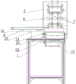
FIG. 1 is a schematic structural view of the present invention;
FIG. 2 is a right side view of FIG. 1 with motor A omitted;
FIG. 3 is a front view of FIG. 1;
FIG. 4 is a top view of FIG. 1;
in the figure, 1-frame, 2-gantry, 3-flat belt conveyor A, 4-flat belt conveyor B, 6-rectangular frame, 7-C-shaped guide rod, 8-longitudinal cylinder, 9-L plate, 10-support plate, 11-frame A, 12-motor A, 13-flat belt A, 14-driving roller A, 15-driven roller A, 16-frame B, 17-motor B, 18-flat belt B, 19-driving roller B, 20-driven roller B, 21-driven pulley, 22-driving pulley, 23-belt, 24-guide sleeve, 25-vertical plate, 26-baffle plate and 27-guide rod.
Detailed Description
The invention will be further described with reference to the accompanying drawings, without limiting the scope of the invention to the following:
as shown in fig. 1 to 4, an automatic turning and filling mechanism for a square butter compound seasoning box comprises a frame 1, a portal frame 2 and a box pushing mechanism, wherein the portal frame 2 and the box pushing mechanism are arranged on the frame 1, the upper end and the lower end of the portal frame 2 are respectively provided with a flat belt conveying device A3 and a flat belt conveying device B4, the flat belt conveying device A3 is arranged in parallel with the flat belt conveying device B4, the flat belt conveying device A3 and the flat belt conveying device B4 are both arranged on the right side of the portal frame 2, the portal frame 2 is further provided with a turning mechanism which is arranged between the flat belt conveying device A3 and the flat belt conveying device B4 and is arranged on the left side of the portal frame 2, the turning mechanism comprises a rectangular frame 6 and C-shaped guide rods 7, the rectangular frame 6 is welded on the portal frame 2, a plurality of C-shaped guide rods 7 are welded on four sides of the rectangular frame 6, and all, last port and flat belt A13 parallel and level of flat belt conveyor A3 of C shape passageway, the lower port of C shape passageway and flat belt B18 of flat belt conveyor B4, it is located the front side of flat belt conveyor B4 to push away box mechanism, pushes away box mechanism and includes vertical cylinder 8, L board 9 and backup pad 10, and backup pad 10 welds on frame 1, and vertical cylinder 8 fixed mounting is on the top surface of backup pad 10, is provided with the L board 9 that is located flat belt B18 top on the piston rod of vertical cylinder 8, and the horizontal plate welding of L board 9 is on the effect end of vertical cylinder 8 piston rod, baffle 26 has set firmly on flat belt conveyor B4's the fuselage B16, and baffle 26 vertically sets up and is located flat belt B18 top, is provided with the support between baffle 26 and the fuselage B16, and baffle 26 sets up in the right side of L board 9.
Flat belt conveyor A3 includes fuselage A11, motor A12, flat belt A13, initiative cylinder A14 and driven roll A15, fuselage A11 welds on portal frame 2, and the left and right sides end of fuselage A11 is installed driven roll A15 and initiative cylinder A14 through the pivot rotation respectively, installs flat belt A13 between initiative cylinder A14 and the driven roll A15, and motor A12 fixed mounting is on fuselage A11, and the output shaft of motor A12 and the pivot of initiative cylinder A14 are through the coupling joint.
Flat belt conveyor B4 includes fuselage B16, motor B17, flat belt B18, driving roll B19 and driven roll B20, fuselage B16 welds on portal frame 2, and the left and right sides end of fuselage B16 is installed driven roll B20 and driving roll B19 through the pivot rotation respectively, installs flat belt B18 between driving roll B19 and the driven roll B20, installs driven pulley 21 in driving roll B19's the pivot, and motor B17 fixed mounting is on fuselage B16, installs driving pulley 22 on motor B17's the output shaft, installs belt 23 between driving pulley 22 and the driven pulley 21.
The welding has a uide bushing 24 on the top surface of backup pad 10, is provided with riser 25 between backup pad 10 and the frame 1, and slidable mounting has guide bar 27 in uide bushing 24, and guide bar 27 is on a parallel with vertical cylinder 8 setting, and the other end of guide bar 27 sets firmly on the horizontal plate of L board 9.
The working process of the invention is as follows:
s1, turning on a motor A12, driving a14 to rotate by a motor A12, driving a14 to rotate a driven roller A15 by a flat belt A13, and at the moment, rotating the flat belt A13 counterclockwise;
s2, turning on a motor B17, driving a driving belt wheel 22 to rotate by a motor B17, driving a driven belt wheel 21 to rotate by the driving belt wheel 22 through a belt 23, driving a driving roller B19 to rotate by the driven belt wheel 21, driving the driving roller B19 to rotate by a driven roller B20 through a flat belt B18, and clockwise rotating the flat belt B18;
s3, placing the cleaned square boxes on a flat belt A13 at intervals with container openings facing downwards by workers, conveying the square boxes towards the upper port of a C-shaped channel by the flat belt A13, enabling the square boxes to sequentially pass through the upper port of the C-shaped channel, the C-shaped channel and the lower port of the C-shaped channel and finally fall onto a flat belt B18, enabling the container openings of the square boxes to face upwards, and blocking the square boxes by a blocking plate 26 under the conveying of the flat belt B18; therefore, the inverted square box is turned over by 180 degrees through the turning mechanism, the container opening of the square box faces to prepare for filling the square butter compound seasoning at the later stage, manual turning is not needed, the labor intensity of workers is greatly reduced, and the production efficiency is improved; in addition, only one worker needs to place the cleaned square box on the flat belt A13, so that the number of workers is greatly reduced, the production cost is saved, and economic benefits and social benefits are brought to production enterprises;
s4, when a plurality of square boxes with required quantity are stacked on the flat belt B18, a worker introduces high-pressure gas into a rodless cavity of the longitudinal cylinder 8, a piston rod drives the L plate 9 to move backwards, the horizontal plate of the L plate 9 pushes the square boxes on the flat belt B18 into the lower part of a filling opening of automatic filling equipment in parallel, square beef tallow compound seasoning can be filled into the square boxes through the automatic filling equipment, and when the L plate 9 moves backwards, the vertical plate of the L plate 9 shields the lower end opening of the C-shaped channel, so that the square boxes in the C-shaped channel are prevented from falling onto the flat belt B18, and stable and undisturbed filling is ensured. Therefore, the box pushing mechanism is matched with the baffle 26 to push the square boxes into the filling station simultaneously in parallel, and workers are not required to splice the square boxes and then send the spliced square boxes into the filling station, so that the labor intensity of the workers is greatly reduced, and the production efficiency is further improved.
Claims (7)
1. The utility model provides an automatic upset of compound condiment box of square butter fills mechanism which characterized in that: the automatic box pushing device comprises a rack (1), a portal frame (2) and a box pushing mechanism, wherein the portal frame (2) is arranged on the rack (1), the upper end and the lower end of the portal frame (2) are respectively provided with a flat belt conveying device A (3) and a flat belt conveying device B (4), the flat belt conveying device A (3) and the flat belt conveying device B (4) are both positioned on the right side of the portal frame (2), the portal frame (2) is also provided with a turnover mechanism positioned between the flat belt conveying device A (3) and the flat belt conveying device B (4), the turnover mechanism is positioned on the left side of the portal frame (2) and comprises a rectangular frame (6) and C-shaped guide rods (7), the rectangular frame (6) is welded on the portal frame (2), a plurality of C-shaped guide rods (7) are welded on four sides of the rectangular frame (6) and are surrounded by C-shaped channels, the upper ports of the C-shaped channels are flush with the flat belt A (13) of the flat belt conveying device A (3, lower port and flat belt B (18) of flat belt conveyor B (4) of C shape passageway, it is located the front side of flat belt conveyor B (4) to push away box mechanism, it includes vertical cylinder (8) to push away box mechanism, L board (9) and backup pad (10), backup pad (10) weld on frame (1), vertical cylinder (8) fixed mounting is on the top surface of backup pad (10), be provided with L board (9) that are located flat belt B (18) top on the piston rod of vertical cylinder (8), the horizontal plate welding of L board (9) is served in the effect of vertical cylinder (8) piston rod, baffle (26) have set firmly on fuselage B (16) of flat belt conveyor B (4), baffle (26) vertically set up and are located flat belt B (18) top, baffle (26) set up in the right side of L board (9).
2. The automatic turning and filling mechanism of a square butter compound seasoning box as claimed in claim 1, wherein: the flat belt conveying device A (3) is arranged in parallel to the flat belt conveying device B (4).
3. The automatic turning and filling mechanism of a square butter compound seasoning box as claimed in claim 1, wherein: the flat belt conveying device A (3) comprises a machine body A (11), a motor A (12), a flat belt A (13), a driving roller A (14) and a driven roller A (15), the machine body A (11) is welded on a portal frame (2), the left end and the right end of the machine body A (11) are respectively provided with the driven roller A (15) and the driving roller A (14) through rotating shafts in a rotating mode, the flat belt A (13) is installed between the driving roller A (14) and the driven roller A (15), the motor A (12) is fixedly installed on the machine body A (11), and the output shaft of the motor A (12) is connected with the rotating shaft of the driving roller A (14) through a coupler.
4. The automatic turning and filling mechanism of a square butter compound seasoning box as claimed in claim 1, wherein: flat belt conveyor B (4) include fuselage B (16), motor B (17), flat belt B (18), driving roll B (19) and driven roll B (20), fuselage B (16) welds on portal frame (2), and driven roll B (20) and driving roll B (19) are installed through the pivot rotation respectively to the end about fuselage B (16), installs flat belt B (18) between driving roll B (19) and driven roll B (20), installs driven pulley (21) in the pivot of driving roll B (19), and motor B (17) fixed mounting is on fuselage B (16), installs driving pulley (22) on the output shaft of motor B (17), installs belt (23) between driving pulley (22) and driven pulley (21).
5. The automatic turning and filling mechanism of a square butter compound seasoning box as claimed in claim 1, wherein: the welding has uide bushing (24) on the top surface of backup pad (10), and slidable mounting has guide bar (27) in uide bushing (24), and guide bar (27) are on a parallel with vertical cylinder (8) setting, and the other end of guide bar (27) sets firmly on the horizontal plate of L board (9).
6. The automatic turning and filling mechanism of a square butter compound seasoning box as claimed in claim 1, wherein: a vertical plate (25) is arranged between the support plate (10) and the frame (1).
7. The automatic turning and filling mechanism of a square butter compound seasoning box as claimed in claim 1, wherein: and a support is arranged between the baffle (26) and the machine body B (16).
Priority Applications (1)
| Application Number | Priority Date | Filing Date | Title |
|---|---|---|---|
| CN201911372269.1A CN110920998A (en) | 2019-12-27 | 2019-12-27 | Automatic overturning and filling mechanism of square beef tallow composite seasoning box |
Applications Claiming Priority (1)
| Application Number | Priority Date | Filing Date | Title |
|---|---|---|---|
| CN201911372269.1A CN110920998A (en) | 2019-12-27 | 2019-12-27 | Automatic overturning and filling mechanism of square beef tallow composite seasoning box |
Publications (1)
| Publication Number | Publication Date |
|---|---|
| CN110920998A true CN110920998A (en) | 2020-03-27 |
Family
ID=69861133
Family Applications (1)
| Application Number | Title | Priority Date | Filing Date |
|---|---|---|---|
| CN201911372269.1A Withdrawn CN110920998A (en) | 2019-12-27 | 2019-12-27 | Automatic overturning and filling mechanism of square beef tallow composite seasoning box |
Country Status (1)
| Country | Link |
|---|---|
| CN (1) | CN110920998A (en) |
Cited By (1)
| Publication number | Priority date | Publication date | Assignee | Title |
|---|---|---|---|---|
| CN115557029A (en) * | 2022-12-05 | 2023-01-03 | 广汉市迈德乐食品有限公司 | Foreign matter detection device based on butter box packing process |
-
2019
- 2019-12-27 CN CN201911372269.1A patent/CN110920998A/en not_active Withdrawn
Cited By (2)
| Publication number | Priority date | Publication date | Assignee | Title |
|---|---|---|---|---|
| CN115557029A (en) * | 2022-12-05 | 2023-01-03 | 广汉市迈德乐食品有限公司 | Foreign matter detection device based on butter box packing process |
| CN115557029B (en) * | 2022-12-05 | 2023-03-14 | 广汉市迈德乐食品有限公司 | Foreign matter detection device based on butter case dress technology |
Similar Documents
| Publication | Publication Date | Title |
|---|---|---|
| CN203887461U (en) | Workpiece welding jig | |
| CN103010699A (en) | Tooling board delivering and taking circulating system | |
| CN203419739U (en) | A sealant automatic filling machine | |
| CN106736602A (en) | Integral type door of elevator produces swinging cross automatically | |
| CN206795096U (en) | One kind pressing welding equipment | |
| CN206767071U (en) | A kind of automatic charging device suitable for more specifications parameter tubing | |
| CN201770018U (en) | Automatic packing device special for oil bushing production line | |
| CN110920998A (en) | Automatic overturning and filling mechanism of square beef tallow composite seasoning box | |
| CN202780291U (en) | a welding device | |
| CN211711206U (en) | Automatic overturning and filling mechanism of square beef tallow composite seasoning box | |
| CN205147697U (en) | Little medium -sized excavator oil tank welding production line device | |
| CN208761663U (en) | A kind of laminate intermediate carrier structure | |
| CN209241997U (en) | Automatic framing machine is used in a kind of production of aluminum profile | |
| CN206455410U (en) | Integral type door of elevator produces swinging cross automatically | |
| CN207312593U (en) | Guide rail jacks electric turntable | |
| CN114643439B (en) | An intelligent crossbar pressure welding device and working method integrating feeding, processing and discharging | |
| CN206519783U (en) | The feeding of novel numerical control carpenter's process equipment and discharging integral mechanism | |
| CN206155861U (en) | Plastic bottle paper holds in palm packagine machine | |
| CN207465576U (en) | Automatic sticky stick assembly line | |
| CN114643438B (en) | An intelligent welding device capable of automatically feeding materials and a working method thereof | |
| CN216541486U (en) | A intelligent welding set that is used for but automatic feeding of steel grating processing | |
| CN204777700U (en) | Turnover mechanism is carried to aerated concrete block's layer board | |
| CN203437839U (en) | Process pipe welding workstation | |
| CN211226298U (en) | Multi-type barrel sharing type liquid filling line | |
| CN207000915U (en) | The stacking frock of electric machine iron core |
Legal Events
| Date | Code | Title | Description |
|---|---|---|---|
| PB01 | Publication | ||
| PB01 | Publication | ||
| SE01 | Entry into force of request for substantive examination | ||
| SE01 | Entry into force of request for substantive examination | ||
| WW01 | Invention patent application withdrawn after publication |
Application publication date: 20200327 |
|
| WW01 | Invention patent application withdrawn after publication |