CN110914788A - Virtual overlays for user interaction in augmented reality - Google Patents
Virtual overlays for user interaction in augmented reality Download PDFInfo
- Publication number
- CN110914788A CN110914788A CN201880047219.3A CN201880047219A CN110914788A CN 110914788 A CN110914788 A CN 110914788A CN 201880047219 A CN201880047219 A CN 201880047219A CN 110914788 A CN110914788 A CN 110914788A
- Authority
- CN
- China
- Prior art keywords
- virtual
- space
- operating member
- controller
- user
- Prior art date
- Legal status (The legal status is an assumption and is not a legal conclusion. Google has not performed a legal analysis and makes no representation as to the accuracy of the status listed.)
- Pending
Links
Images


Classifications
-
- G—PHYSICS
- G06—COMPUTING OR CALCULATING; COUNTING
- G06F—ELECTRIC DIGITAL DATA PROCESSING
- G06F3/00—Input arrangements for transferring data to be processed into a form capable of being handled by the computer; Output arrangements for transferring data from processing unit to output unit, e.g. interface arrangements
- G06F3/01—Input arrangements or combined input and output arrangements for interaction between user and computer
- G06F3/011—Arrangements for interaction with the human body, e.g. for user immersion in virtual reality
-
- G—PHYSICS
- G02—OPTICS
- G02B—OPTICAL ELEMENTS, SYSTEMS OR APPARATUS
- G02B27/00—Optical systems or apparatus not provided for by any of the groups G02B1/00 - G02B26/00, G02B30/00
- G02B27/01—Head-up displays
- G02B27/017—Head mounted
-
- G—PHYSICS
- G06—COMPUTING OR CALCULATING; COUNTING
- G06F—ELECTRIC DIGITAL DATA PROCESSING
- G06F3/00—Input arrangements for transferring data to be processed into a form capable of being handled by the computer; Output arrangements for transferring data from processing unit to output unit, e.g. interface arrangements
- G06F3/01—Input arrangements or combined input and output arrangements for interaction between user and computer
- G06F3/048—Interaction techniques based on graphical user interfaces [GUI]
- G06F3/0481—Interaction techniques based on graphical user interfaces [GUI] based on specific properties of the displayed interaction object or a metaphor-based environment, e.g. interaction with desktop elements like windows or icons, or assisted by a cursor's changing behaviour or appearance
- G06F3/04815—Interaction with a metaphor-based environment or interaction object displayed as three-dimensional, e.g. changing the user viewpoint with respect to the environment or object
-
- G—PHYSICS
- G06—COMPUTING OR CALCULATING; COUNTING
- G06F—ELECTRIC DIGITAL DATA PROCESSING
- G06F3/00—Input arrangements for transferring data to be processed into a form capable of being handled by the computer; Output arrangements for transferring data from processing unit to output unit, e.g. interface arrangements
- G06F3/01—Input arrangements or combined input and output arrangements for interaction between user and computer
- G06F3/048—Interaction techniques based on graphical user interfaces [GUI]
- G06F3/0484—Interaction techniques based on graphical user interfaces [GUI] for the control of specific functions or operations, e.g. selecting or manipulating an object, an image or a displayed text element, setting a parameter value or selecting a range
-
- G—PHYSICS
- G06—COMPUTING OR CALCULATING; COUNTING
- G06F—ELECTRIC DIGITAL DATA PROCESSING
- G06F3/00—Input arrangements for transferring data to be processed into a form capable of being handled by the computer; Output arrangements for transferring data from processing unit to output unit, e.g. interface arrangements
- G06F3/16—Sound input; Sound output
- G06F3/167—Audio in a user interface, e.g. using voice commands for navigating, audio feedback
-
- G—PHYSICS
- G06—COMPUTING OR CALCULATING; COUNTING
- G06T—IMAGE DATA PROCESSING OR GENERATION, IN GENERAL
- G06T19/00—Manipulating 3D models or images for computer graphics
- G06T19/006—Mixed reality
-
- G—PHYSICS
- G16—INFORMATION AND COMMUNICATION TECHNOLOGY [ICT] SPECIALLY ADAPTED FOR SPECIFIC APPLICATION FIELDS
- G16H—HEALTHCARE INFORMATICS, i.e. INFORMATION AND COMMUNICATION TECHNOLOGY [ICT] SPECIALLY ADAPTED FOR THE HANDLING OR PROCESSING OF MEDICAL OR HEALTHCARE DATA
- G16H20/00—ICT specially adapted for therapies or health-improving plans, e.g. for handling prescriptions, for steering therapy or for monitoring patient compliance
- G16H20/40—ICT specially adapted for therapies or health-improving plans, e.g. for handling prescriptions, for steering therapy or for monitoring patient compliance relating to mechanical, radiation or invasive therapies, e.g. surgery, laser therapy, dialysis or acupuncture
-
- G—PHYSICS
- G16—INFORMATION AND COMMUNICATION TECHNOLOGY [ICT] SPECIALLY ADAPTED FOR SPECIFIC APPLICATION FIELDS
- G16H—HEALTHCARE INFORMATICS, i.e. INFORMATION AND COMMUNICATION TECHNOLOGY [ICT] SPECIALLY ADAPTED FOR THE HANDLING OR PROCESSING OF MEDICAL OR HEALTHCARE DATA
- G16H40/00—ICT specially adapted for the management or administration of healthcare resources or facilities; ICT specially adapted for the management or operation of medical equipment or devices
- G16H40/60—ICT specially adapted for the management or administration of healthcare resources or facilities; ICT specially adapted for the management or operation of medical equipment or devices for the operation of medical equipment or devices
- G16H40/63—ICT specially adapted for the management or administration of healthcare resources or facilities; ICT specially adapted for the management or operation of medical equipment or devices for the operation of medical equipment or devices for local operation
-
- G—PHYSICS
- G02—OPTICS
- G02B—OPTICAL ELEMENTS, SYSTEMS OR APPARATUS
- G02B27/00—Optical systems or apparatus not provided for by any of the groups G02B1/00 - G02B26/00, G02B30/00
- G02B27/01—Head-up displays
- G02B27/0101—Head-up displays characterised by optical features
- G02B2027/014—Head-up displays characterised by optical features comprising information/image processing systems
-
- G—PHYSICS
- G02—OPTICS
- G02B—OPTICAL ELEMENTS, SYSTEMS OR APPARATUS
- G02B27/00—Optical systems or apparatus not provided for by any of the groups G02B1/00 - G02B26/00, G02B30/00
- G02B27/01—Head-up displays
- G02B27/017—Head mounted
- G02B2027/0178—Eyeglass type
-
- G—PHYSICS
- G02—OPTICS
- G02B—OPTICAL ELEMENTS, SYSTEMS OR APPARATUS
- G02B27/00—Optical systems or apparatus not provided for by any of the groups G02B1/00 - G02B26/00, G02B30/00
- G02B27/01—Head-up displays
- G02B27/0179—Display position adjusting means not related to the information to be displayed
- G02B2027/0187—Display position adjusting means not related to the information to be displayed slaved to motion of at least a part of the body of the user, e.g. head, eye
-
- G—PHYSICS
- G06—COMPUTING OR CALCULATING; COUNTING
- G06F—ELECTRIC DIGITAL DATA PROCESSING
- G06F3/00—Input arrangements for transferring data to be processed into a form capable of being handled by the computer; Output arrangements for transferring data from processing unit to output unit, e.g. interface arrangements
- G06F3/01—Input arrangements or combined input and output arrangements for interaction between user and computer
- G06F3/011—Arrangements for interaction with the human body, e.g. for user immersion in virtual reality
- G06F3/012—Head tracking input arrangements
-
- G—PHYSICS
- G06—COMPUTING OR CALCULATING; COUNTING
- G06F—ELECTRIC DIGITAL DATA PROCESSING
- G06F3/00—Input arrangements for transferring data to be processed into a form capable of being handled by the computer; Output arrangements for transferring data from processing unit to output unit, e.g. interface arrangements
- G06F3/01—Input arrangements or combined input and output arrangements for interaction between user and computer
- G06F3/011—Arrangements for interaction with the human body, e.g. for user immersion in virtual reality
- G06F3/013—Eye tracking input arrangements
-
- G—PHYSICS
- G06—COMPUTING OR CALCULATING; COUNTING
- G06F—ELECTRIC DIGITAL DATA PROCESSING
- G06F3/00—Input arrangements for transferring data to be processed into a form capable of being handled by the computer; Output arrangements for transferring data from processing unit to output unit, e.g. interface arrangements
- G06F3/01—Input arrangements or combined input and output arrangements for interaction between user and computer
- G06F3/017—Gesture based interaction, e.g. based on a set of recognized hand gestures
Landscapes
- Engineering & Computer Science (AREA)
- Theoretical Computer Science (AREA)
- General Engineering & Computer Science (AREA)
- Physics & Mathematics (AREA)
- General Physics & Mathematics (AREA)
- Human Computer Interaction (AREA)
- Health & Medical Sciences (AREA)
- General Health & Medical Sciences (AREA)
- Epidemiology (AREA)
- Medical Informatics (AREA)
- Primary Health Care (AREA)
- Public Health (AREA)
- Biomedical Technology (AREA)
- Software Systems (AREA)
- Computer Hardware Design (AREA)
- Computer Graphics (AREA)
- Multimedia (AREA)
- Audiology, Speech & Language Pathology (AREA)
- Optics & Photonics (AREA)
- General Business, Economics & Management (AREA)
- Business, Economics & Management (AREA)
- Urology & Nephrology (AREA)
- Surgery (AREA)
- Nuclear Medicine, Radiotherapy & Molecular Imaging (AREA)
- User Interface Of Digital Computer (AREA)
Abstract
A controller for augmented reality in a three-dimensional (3D) space comprising: a memory storing instructions; and a processor to execute the instructions. The controller controls a display system configured to render virtual objects in a 3D space. The instructions, when executed by the processor, cause the controller to perform processes. The process includes detecting a first action made by a user with respect to an object or virtual object in 3D space. The process also includes selectively enabling or disabling the virtual operating member based on detecting a first action between the user and an object or virtual object in the 3D space. The virtual operating member is configured to control operation of the machine in the 3D space when operated.
Description
Background
Medical procedures, such as interventional procedures, use physical equipment that is controlled using physical operating members, such as buttons, dials, joysticks, handles, and similar mechanisms, for opening and closing the equipment and changing settings.
Augmented reality generally refers to when supplementing a live image stream with additional computer-generated information. The live image stream may be via eye, camera or communication device (e.g. smart phone and desk). The live image stream is enhanced by being displayed to the user via glasses, contact lenses, projection, or on a communication device. Current augmented reality systems can sense and respond to various user actions including gesture recognition, head tracking, eye tracking, and voice recognition.
With augmented reality implemented in a medical setting, it would be possible for the virtual operating member to be used to control physical equipment. In the same manner as the inadvertent operation of the physical operating member is dangerous, the inadvertent operation of the virtual operating member will also be dangerous.
Disclosure of Invention
According to one aspect of the present disclosure, a controller for augmented reality in a three-dimensional (3D) space includes: a memory storing instructions; and a processor to execute the instructions. The controller controls a display system configured to render virtual objects in a 3D space. The instructions, when executed by the processor, cause the controller to perform a process. The process comprises the following steps: a first motion made by a user relative to an object or virtual object in 3D space is detected. The process also includes selectively enabling or disabling the virtual operating member based on detecting a first action between the user and an object or virtual object in the 3D space. The virtual operating member is configured to control, when operated, operation of the machine in the 3D space.
According to another aspect of the present disclosure, a method for controlling features in a 3D space with augmented reality includes controlling a display system configured to present virtual objects in the 3D space. The method also includes detecting a first action made by the user with respect to an object or virtual object in the 3D space. The method also includes selectively enabling or disabling the virtual operating member based on detecting a first action between the user and an object or virtual object in the 3D space. The virtual operating member is configured to control operation of the machine in the 3D space when operated.
Drawings
The example embodiments are best understood from the following detailed description when read with the accompanying drawing figures. It is emphasized that the various features are not necessarily drawn to scale. In fact, the dimensions may be arbitrarily increased or decreased for clarity of discussion. Wherever applicable and practical, like reference numerals refer to like elements.
FIG. 1A illustrates a process of a virtual overlay for user interaction in augmented reality, in accordance with a representative embodiment;
FIG. 1B illustrates another process of a virtual overlay for user interaction in augmented reality, in accordance with a representative embodiment;
fig. 2A illustrates a front view of a head mounted device for a virtual overlay for user interaction in augmented reality, in accordance with an aspect of the present disclosure;
fig. 2B illustrates a side view of a head mounted device for a virtual overlay for user interaction in augmented reality, in accordance with an aspect of the present disclosure;
fig. 2C illustrates a top view of a head mounted device for a virtual overlay for user interaction in augmented reality, in accordance with an aspect of the present disclosure;
fig. 3A illustrates a 3D space in which an object is wearing a head mounted device of a virtual overlay for user interaction in augmented reality, in accordance with an aspect of the present disclosure;
fig. 3B illustrates another view of the 3D space in fig. 3A, wherein the medical equipment is provided with an augmented reality interface and virtual operating members and virtual overlays for user interaction in augmented reality, in accordance with an aspect of the present disclosure;
FIG. 4 illustrates a logical arrangement that illustrates operational control of a device using a virtual overlay for user interaction in augmented reality, in accordance with an aspect of the present disclosure;
FIG. 5A illustrates a top view of another head mounted device for a virtual overlay for user interaction in augmented reality, in accordance with an aspect of the present disclosure;
fig. 5B illustrates a top view of another head mounted device for a virtual overlay for user interaction in augmented reality, in accordance with an aspect of the present disclosure;
FIG. 6 illustrates an exemplary general-purpose computer system including a set of instructions for a virtual overlay for user interaction in augmented reality, in accordance with an aspect of the present disclosure;
FIG. 7 illustrates another process for a virtual overlay for user interaction in augmented reality according to an aspect of the present disclosure;
FIG. 8 illustrates another process for a virtual overlay for user interaction in augmented reality, in accordance with a representative embodiment;
FIG. 9A illustrates an embodiment of using a virtual overlay for user interaction to enable a virtual operating member in accordance with a representative embodiment; and is
Fig. 9B illustrates another embodiment of enabling a virtual operating member to control operation of a machine in a 3D space, according to a representative embodiment.
Detailed Description
In the following detailed description, for purposes of explanation and not limitation, representative embodiments disclosing specific details are set forth in order to provide a thorough understanding of an embodiment according to the present teachings. Descriptions of well-known systems, devices, materials, methods of operation, and methods of manufacture may be omitted so as to not obscure the description of the representative embodiments. Nonetheless, systems, devices, materials, and methods that are within the knowledge of one of ordinary skill in the art are within the scope of the present teachings and may be used in accordance with the representative embodiments. It is noted that the terminology used herein is for the purpose of describing particular embodiments only and is not intended to be limiting. The defined terms are complementary to the technical and scientific meanings of the defined terms as commonly understood and accepted in the technical field of the present teaching.
It will be understood that, although the terms first, second, third, etc. may be used herein to describe various elements or components, these elements or components should not be limited by these terms. These terms are only used to distinguish one element or component from another element or component. Thus, a first element or component discussed below could be termed a second element or component without departing from the teachings of the inventive concept.
The terminology used herein is for the purpose of describing embodiments only and is not intended to be limiting. As used in the specification and in the claims, the singular form of the terms "a", "an" and "the" are intended to include both the singular and the plural, unless the context clearly dictates otherwise. Furthermore, the terms "comprises" and/or "comprising," and/or similar terms, when used in this specification, specify the presence of stated features, elements, and/or components, but do not preclude the presence or addition of one or more other features, elements, components, and/or groups thereof. As used herein, the term "and/or" includes all combinations of one or more of the associated listed items.
Unless otherwise indicated, when an element or component is referred to as being "connected to," "coupled to," or "adjacent to" another element or component, it will be understood that the element or component may be directly connected or coupled to the other element or component or intervening elements or components may be present. That is, these and similar terms encompass the case where one or more intermediate elements or components may be employed to connect two elements or components. However, when an element or component is referred to as being "directly connected" to another element or component, this only encompasses the case where the two elements or components are connected to each other without any intervening or intervening elements or components.
In view of the foregoing, the present disclosure, through one or more of its various aspects, embodiments, and/or specific features or sub-components, is therefore intended to present one or more of the advantages as particularly pointed out below. For purposes of explanation and not limitation, example embodiments disclosing specific details are set forth in order to provide a thorough understanding of an embodiment according to the present teachings. However, other embodiments consistent with the present disclosure that depart from the specific details disclosed herein remain within the scope of the claims. Moreover, descriptions of well-known apparatus and methods may be omitted so as to not obscure the description of the example embodiments. Such methods and apparatus are within the scope of the present disclosure.
FIG. 1A illustrates a process of a virtual overlay for user interaction in augmented reality, according to a representative embodiment. The process illustrated in FIG. 1A may represent an overall process of implementing selective enabling or disabling of virtual operating members based on detected user actions or commands. As described herein, the virtual operating member may be a virtual button, a virtual dial, a virtual joystick, a virtual handle, or other virtual member visible using software that generates the virtual member as augmented reality in 3D space. The virtual operating member may be specifically related to the operation of a machine such as medical equipment. In other words, a user interacting with the virtual operating member can operate the machine.
The control described herein is not limited to any particular type of machine, or even to a machine at all. Instead, the control via the virtual operating member may have a form of a machine, setting, information, and other forms of items and information that can be controlled by, for example, opening and closing. Examples include images on a screen, pointers, features such as playing music, and so forth. Various examples of controllable items and information are set forth below following the description of fig. 1A and 1B.
In addition, control may include enabling and disabling individual controllable items and information, or all groups or subsets of all controllable items and information. For example, the virtual operating member may be an emergency control to immediately display a set of specified information from a set of electron sources monitoring the patient when the patient's vital signs rapidly deteriorate. The emergency control may be enabled and activated quickly using, for example, an encoded command or sequence of commands. Of course, the master control for all or a subset of all controllable items and information is not limited to emergency situations and may be applied, for example, when closing the 3D space after a session or other time.
The process in fig. 1A begins with pre-mapping/pre-registering a 3D space at S111. The 3D space may be, for example, an operating room or other enclosed space to be used during an augmented reality session. A virtual operating member as described herein occupies a portion of the 3D space. The 3D space may be mapped prior to the session providing the augmented reality, so the mapping at S111 is in a sense pre-mapped. The mapping may be performed by visually capturing all physical parameters of the 3D space and any physical items (e.g., furniture, equipment) in the 3D space. The 3D space may also be registered prior to the session providing the augmented reality, so the registration at S111 is also pre-registered in a sense. The registration may be performed by labeling each physical parameter of the 3D space and each physical item in the 3D space.
The computer program for mapping and registering the 3D space may be linked to a library of properties of physical parameters and physical items. The library of characteristics may be used to facilitate registration by linking any physical parameters or physical items identified in the mapping with a predetermined description. The mapping and registration is performed such that all regions in the 3D space where virtual objects can be placed can be identified.
The mapping and registration may also be performed at the time of the AR session. For example, although the mapping at S11 was described above as pre-mapping, the 3D space may also be mapped dynamically after the augmented reality session begins, for example by using sensors of the augmented reality device to collect parameters of the 3D space and then using image recognition to register physical parameters and physical items in the 3D space.
At S122, a virtual operation member is set in the 3D space. As mentioned above, the virtual operating member may represent a physical operating member for controlling the machine. For example, the type of virtual operating member may be retrieved from a library that specifies different types and appearances of buttons, dials, joysticks, handles, and similar forms of mechanical or electromechanical input. The position of the virtual operation member may also be set in the 3D space, for example, by virtually moving the virtual operation member with a gesture to place the virtual operation member at a specific position in the mapped 3D space. Of course, the position of the virtual operating member may also be manipulated using, for example, a mouse, joystick, touch screen, roll-pad, or other forms of input known to computers and electronic devices.
At S133, the virtual operation member is correlated with a specific operation of the machine in the 3D space. For example, the virtual operating member may be associated with turning an X-ray machine on or off, or with capturing an image or reading using the machine. The operation of the virtual operating member may be related at a number of levels, including in software that captures and interprets user actions or commands relative to the virtual operating member and in software that controls the operation of the machine.
At S144, a cover for the virtual operation member is set in the 3D space. May correspond to the type of overlay selected from the library. The overlay may be given the appearance of a physical overlay, such as an overlay for a touch pad that hides the buttons on the touch pad from view and thus cannot be manipulated. In the same manner, the cover provided at S144 may be used to visually hide the virtual operating member in augmented reality. The position of the overlay can be set in 3D space, for example, by virtually moving the overlay with a gesture to place the overlay at a particular location mapped in 3D space. The position of the virtual operating member may also be manipulated using, for example, a mouse, joystick, touch screen, anti-roll pad, or other forms of input known in computers and electronic devices.
At S155, the covering is correlated with the operation of the virtual operating member and the machine. That is, the overlays can be logically related in augmented reality software to hide or unhide the virtual operating members in augmented reality when manipulated. The operation of the covering may also be related in software that controls the operation of the machine, for example by disabling the operation of the machine when the covering is "over" the virtual operating member. In this way, the virtual operating member will not be accidentally manipulated, as it will not be visible in the augmented reality space comprising the virtual operating member and the covering.
At S166, the overlay is correlated with predefined user actions and commands. The predefined user actions and commands are specific actions and commands that are to be interpreted as instructions to activate the covering or deactivate the covering, for example by moving the covering over the virtual operating member. For example, a sliding motion on or immediately around a covering from left to right may be interpreted as "opening" the covering when closed, while a sliding motion from right to left may be interpreted as "closing" the covering when open. The augmented reality software may also interpret verbal instructions such as "open cover" or "close cover" to correspond to particular actions taken with respect to the cover.
At S177, an augmented reality session is initiated. When a first object wearing a head-mounted device enters a 3D space, an augmented reality session may be considered to begin. Further, multiple augmented reality sessions may occur simultaneously, where each of multiple different objects wearing the head-mounted device individually enter the 3D space. The head-mounted device may be pre-programmed or pre-authorized to access the portion of the 3D space occupied by the virtual operating member and the covering. For example, an augmented reality session may correspond to a medical intervention occurring in a pre-mapped operating room used as a 3D space, and each subject authorized to access a virtual reality object may access information displayed via virtual reality during the medical intervention.
At S188, one of the predefined user actions or commands from S166 may be detected, and at S199, the virtual operating member may be selectively enabled or disabled based on the detected user action or command. That is, a predetermined action to open the virtual covering may be detected at S188, and then both the augmented reality software and the software for operating the machine may accept a command to operate the machine using the virtual operating member.
The virtual operating member and the overlay may be visible via augmented reality using the head-mounted device. However, augmented reality is not limited to head-mounted devices. In contrast, the head mounted device is easily explained in the context of a 3D space such as an operating room, and is used as an example for convenience. The virtual operating member and the cover occupying a part of the 3D space can be displayed as augmented reality to any authorized object with the 3D space including the virtual operating member and the cover as a viewpoint. Alternatively, the virtual operating member and covering may be visible only to one or a subset of designated users who will be authorized to manually operate the machine associated with the virtual operating member and covering. For example, even a remote user viewing the 3D space via a camera may have access to the virtual operating member when the remote user is so authorized. In addition to head-mounted devices, users with access to virtual operating members and overlays can use projected images, transparent heads-up displays, and other forms of augmented reality devices.
FIG. 1B illustrates another process of a virtual overlay for user interaction in augmented reality, in accordance with a representative embodiment. The process shown in FIG. 1B may again represent the entire process of implementing the selective enabling or disabling of virtual operating members based on detected user actions or commands. Several of the activities shown in fig. 1B are the same as those shown in fig. 1A, and thus a detailed explanation is not repeated.
The process in fig. 1B begins with pre-mapping/pre-registering the 3D space at S111, and includes setting a virtual operating member in the 3D space at S122 and correlating the virtual operating member with the operation of the machine in the 3D space at S133.
At S145, a physical enabling/disabling object is set for the virtual operation member in the 3D space. For example, a foot pedal near or below the bed in the 3D space may be associated with enabling or disabling the virtual operating member. In this way and by way of example, a user may be required to depress a foot pedal to view a virtual operating member in augmented reality, and then interact with the virtual operating member in augmented reality space to operate the machine system in 3D space. One example of how this can be used to provide shielding is an X-ray device, where a user must combine physical actions with interactions in augmented reality to find an "on" button and then virtually interact with the "on" button to operate the X-ray device.
At S156, the physical enable/disable object is correlated with the operation of the virtual operating member and the machine. That is, the physical enable/disable object may be logically related in the augmented reality software to hide or unhide the virtual operating member in augmented reality when manipulated. The operation of the physical enable/disable object may also be related in the software that controls the operation of the machine, for example by disabling the operation of the machine when the physical enable/disable feature is not pressed. In this way, the virtual operating member is not accidentally manipulated, as it will not be visible in the augmented reality space comprising the virtual operating member.
At S167, the physical enable/disable object is correlated with predefined user actions and commands. The predefined user actions and commands are specific actions and commands that will be interpreted as instructions to activate physical enablement/disablement and are limited here compared to the virtual overlay used in FIG. 1A. For example, one foot pedal may have only 2 or possibly on and off readings.
At S177, an augmented reality session is initiated, and at S188, a predefined user action or command is detected during the augmented reality session. At S199, the virtual operating member is selectively enabled or disabled based on the detected user action or command. For example, as described above, a user stepping on a foot pedal may activate or deactivate a virtual operating member for operating the machine.
In embodiments herein, control is not limited to operation of a particular type of machine, or even to operation of a machine at all. Rather, as examples, controls may include X-ray machines, ultrasound machines, robots (e.g., surgical robots), electromechanical environmental controls for rooms, and the operation of various types of medical equipment. However, the control may also be control of virtual information and other types of devices that may not meet the particular definition of a machine. Examples of machines and other mechanisms that may be controlled include:
an X-ray machine:
c type arm, physical location of the workbench.
X-ray configuration, e.g. dose level, wedge, collimation.
Image display, e.g. bringing up different images for viewing, obscuring images, annotation.
An ultrasonic machine:
image acquisition parameters such as focus, depth, gain.
Display parameters, such as rotated images.
Robots, such as catheter robots, surgical robots.
Electromechanical environment or room control:
o lights on/off.
Sound, e.g. music, audio communication with the control room.
O timer on/off.
Note on/off.
Voice or camera recording on/off.
Other equipment, such as IVTJS, FFR, patient vital signs, anesthesia equipment.
Virtual information:
control what is to be displayed, e.g. which screens and where.
Pointer or selector for virtual information, e.g. place landmarks, select certain objects, annotate images/models.
Omicron interacts with the model (rotates, grows, or shrinks, etc.).
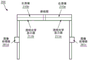
Fig. 2A illustrates a front view of a head mounted device for a virtual overlay for user interaction in augmented reality, in accordance with an aspect of the present disclosure. In fig. 2A, the head mounted device 200 includes a frame 201 in which a right lens 210a and a left lens 210b are respectively enclosed. The sensor 250, camera 260 represent electronic components integrated within and/or on the frame 201.
As explained herein, the left lens 210b and the right lens 210a may each be provided in front of or behind the transparent optical display. The transparent optical display may be controlled by the image processor to generate a virtual object that is superimposed in the field of view of the subject wearing the head-mounted device 200. Alternatively, the left lens 210b and the right lens 210a may be respectively disposed in front of mirrors that reflect light from the projector into the eyes of the subject wearing the head-mounted device 200. The effect of the mirror is the same as using a transparent optical display, where the virtual object is superimposed in the field of view of the body wearing the head-mounted device 200.
From the perspective of the body wearing the head mounted device 200, the camera 260 faces forward to provide a forward view. Camera 260 may represent multiple cameras, including different types of cameras (RBG, grayscale, depth sensing camera, IR camera, spectral camera). The sensors 250 sense aspects of the environment surrounding the head mounted device 200.
The sensors 250 may include, for example, accelerometers, gyroscopes, resistive sensors, current sensors, piezoelectric sensors, voltage sensors, capacitive sensors, global positioning satellite receivers, compasses, altimeters, cameras, rangefinders, microphones, thermometers, chemical sensors, humidity sensors, and the like. The sensors 250 sense movement of the body wearing the head-mounted device 200, such as when and to what extent the body is tilting or rotating its head. The sensors 250 also sense environmental conditions of the environment surrounding the head mounted device 200, such as temperature and humidity, lighting conditions, and the like. As explained below with respect to fig. 2C, the cameras 270a, 270b may also be provided as sensors to track the eye movements of the operator.
Fig. 2B illustrates a side view of a head mounted device for a virtual overlay for user interaction in augmented reality according to an aspect of the present disclosure. In fig. 2B, right temple 202a is shown extending from lens group 210 enclosed in frame 201. As shown in fig. 2A, the lens group 210 includes a right lens 210a and a left lens 210 b.
The right temple 202a is used for the right side of the head of the main body wearing the head-mounted device 200. As explained below with respect to fig. 2C, a left temple 202b is provided for wearing the left side of the head of the main body of the head-mounted device 200. The right temple 202a is used to hold the head-mounted device 200 over the ear of the subject wearing the head-mounted device 200. As shown in fig. 2A, the middle portion of the front of the head mounted device 200 may also be balanced over the nose of the subject wearing the head mounted device 200.
Fig. 2C illustrates a top view of a head mounted device for a virtual overlay for user interaction in augmented reality, in accordance with an aspect of the present disclosure. In fig. 2C, various electronic components are shown disposed along the right temple 202a and the left temple 202 b. The elements include a camera 270a along the right temple 202a and a camera 270b along the left temple 202 b. The left temple 202b also includes a processor 280b and a memory 281b, while the right temple 202a also includes a processor 280a and a memory 281 a. The processors 280a, 280b and memories 281a, 281b represent elements of a general purpose computer system that may be fully or partially embodied in the head-mounted device 200.
The cameras 270a, 270b face rearward and are used to capture eye movements of the subject wearing the head-mounted device 200. Although the cameras 270a, 270b are shown separate from the sensors 250 from fig. 2A, the cameras 270a, 270b are consistent with the type of sensors 250 in which they sense movement of the eyes of the subject wearing the head-mounted device 200.
The memories 281a, 281b store instructions and data for the head mounted device 200, and the processors 280a, 280b execute the instructions for the head mounted device 200. The instructions stored in the memory 281a, 281b and executed by the processor 280a, 280b may include instructions for generating a particular virtual object to be superimposed in the field of view of the body wearing the head-mounted device 200. The combination of the memory 281a and the processor 280a may be considered a controller as described herein. Similarly, the combination of memory 28lb and processor 280b may be considered a controller as described herein. Of course, the entirety of the head mounted device 200 may be considered a controller as described herein.
Fig. 3A illustrates a space in which a subject wears a head-mounted device for a virtual overlay for user interaction in augmented reality, according to an aspect of the present disclosure. In fig. 3A, five bodies 381-385 are shown arranged around the table 399 in the 3D space 300. Also in fig. 3A, centralized computer 390 is illustrated with a wireless interface 393, a processor 391, and a memory 392.
The embodiment of fig. 3A illustrates the danger of providing a virtual operating member in a crowded and enclosed space. In the embodiment of FIG. 3A, five bodies 381-385 may each wear a head mounted device 200a-200e for augmented reality. If a virtual operating member is shown in the shared augmented reality space accessed by each of the five subjects 381-385, any of the five subjects may inadvertently activate the virtual operating member. Thus, a cover or other enabling/disabling feature for the virtual operating member is provided to disable the virtual operating member when not in use. Furthermore, the right to enable the virtual operating member may be limited to less than all users and may require authentication by, for example, a password.
The centralized computer 390 may be used to initially control augmented reality, for example, by inputting settings for each virtual operating member and object and/or virtual object in the 3D space 300 that may be used to disable and enable each virtual operating member. When the head mounted devices 200a-200e are activated, control of the 3D space may be passed to one of the five bodies 381-385. The transfer of control may be in accordance with predetermined instructions stored in memory 392 and executed by processor 391. The predetermined instructions for controlling the 3D space 300 may allow one of the five bodies 381-385 or another body in the 3D space 300 or outside the 3D space 300 to change the control of the 3D space.
The five bodies 381-385 include a first body 381, a second body 382, a third body 383, a fourth body 384, and a fifth body. The first body 381 wears a first head mounted device 200a, the second body 382 wears a second head mounted device 200b, the third body 383 wears a third head mounted device 200c, the fourth body 384 wears a fourth head mounted device 200d, and the fifth body 385 wears a fifth head mounted device 200 e. Each of the first, second, third, fourth, and fifth head-mounted devices 200a, 200b, 200C, 200d, 200e described herein may include any of the features described in detail with respect to the head-mounted device 200 shown in fig. 2A-2C. In addition, each of the head mounted devices 200a-200e may be wirelessly connected to each of the other head mounted devices 200a-200e, as well as to the centralized computer 390. Each of the head-mounted devices 200a-200e may also be tethered to a centralized computer 390.
The 3D space 300 may be a room, e.g. an operating room in a hospital, and the five bodies 381 and 385 may be personnel, such as medical personnel involved in medical interventions on a patient disposed on the table 399. The teachings of the present disclosure are not limited to operating rooms or medical personnel, but for convenience, reference may be repeated to such an arrangement of the teachings herein.
In the operating room example, the five subjects 381-385 may each have different responsibilities and rely on different information sources that provide different kinds of information. Five bodies 381-385 may also have responsibility for relying on the same information source or multiple information sources. As shown in fig. 3A, it would be difficult to provide a common source of information to the five subjects 381-385 via a single monitor, as they are disposed around the table 399, and this is particularly difficult for any person who needs to visually monitor the patient directly on the table 399.
The 3D space 300 is an enclosure such as an operating room and may be pre-mapped such that each physical object in the 3D space 300 is mapped to prepare a virtual overlay for user interaction in augmented reality as described herein. Thus, each of the five bodies 381-385 may be provided with augmented reality using a pre-mapping of 3D space. That is, the pre-mapping provides physical constraints that cannot be changed, while the virtual object may be provided in a location in 3D space that does not conflict with the pre-mapped physical constraints.
In FIG. 3A, head mounted devices 200a-200e are used to provide a virtual overlay for user interaction in virtual reality. Each head-mounted device 200 is configured to provide a transparent interface to the body wearing the head-mounted device 200 such that the subject is seen from a constant perspective to the physical world as seen through the head-mounted device 200 when not augmented with real time. When augmented as described herein, the head-mounted device 200 is used to augment a view of the physical world with virtual objects superimposed in the view of the physical world.
A dedicated unshared portion of the 3D space may be provided by the head mounted devices 200a-200e to each of the subjects 281, 285. In other words, each of the head-mounted devices 200a-200e may uniquely provide a dedicated portion of the 3D space for the corresponding subject that does not appear to the other head-mounted device 200a-200e in the view of the 3D space. These dedicated portions, which are shown in the view of only one of the five bodies 381-385, are described herein as non-shared portions.
Access to a dedicated shared portion of the 3D space may also be provided by the head mounted devices 200a-200e to all of the subjects 281-. The virtual operating members may be individually provided to a user (e.g., an X-ray technician) in a non-shared portion of the 3D space, or may be provided to a user group (e.g., a plurality of nurses) in a shared portion of the 3D space.
Fig. 3B illustrates another view of the 3D space in fig. 3A, wherein the medical equipment is provided with an augmented reality interface for a virtual overlay for user interaction in augmented reality, in accordance with an aspect of the present disclosure. In fig. 3B, a number of different electronic devices are used to monitor and/or display medical information of the patient on the table 399.
Camera number one 383 is used to provide a video feed of the patient during the medical intervention. An augmented reality interface 383A is used to selectively provide video feeds from camera number one 383 to people via augmented reality.
The first modality computer 381 is used to obtain and display medical information from sensors on or around the patient. The augmented reality interface 381A is used to selectively provide medical information to a person via augmented reality. Further, three virtual operating members 384, 385 and 386 are provided for the first modality computer 381. Each of the three virtual operating members 384, 385 and 386 is covered with a respective virtual covering 384A, 385A and 386A.
The second modality computer 382 is also used to obtain and display medical information from sensors on or around the patient. The augmented reality interface 382A is used to selectively provide medical information to a person via augmented reality. Further, three virtual operating members 387, 388, and 389 are provided for the first modality computer 381. Each of the three virtual operating members 387, 388 and 389 is covered with a virtual covering 387A, 388A and 389A.
In the embodiment of fig. 3A and 3B, the virtual operation members 384-. The software for such augmented reality devices must be authorized to display the virtual operation members 384-. In other words, the user may even be restricted from viewing any of the virtual operations member 384-. Limiting unnecessary user access to augmented reality features is another mechanism for avoiding accidental activation or control of the first or second modality computers 381, 382.
A centralized computer 390 is shown in fig. 3B and may be used to control, at least initially, the augmented reality provided via the shared portion of the 3D space 300. As described above, centralized computer 390 comprises a processor 391, a memory 392, and a wireless interface 393. The centralized computer 390 may control both the shared portion(s) and the unshared portion of the 3D space by limiting the ability to view the shared portion(s), limiting the ability to alter feeds provided via the shared portion(s), and limiting the ability to interact within the shared portion(s). Additionally, any data feed from the first or second modality computers 381, 382 or other equipment provided via an unshared or shared augmented reality screen may be routed through the centralized computer 390 or another centralized device such that control of information provided via augmented reality in the 3D space 300 is typically implemented at a single point, even if additional control is implemented without the centralized computer 390 or other centralized device. The control provided by the centralized computer 390 may change, for example, when an authorized user switches control of the shared portion(s) from the centralized computer 390 to another authorized user using, for example, the headset 200.
As an example of fig. 3B, the 3D space 300 may be a sample room layout of an operating room for complex minimally invasive structural cardiac procedures. In this procedure, a plurality of people in the room need to work to treat the patient.
These persons may include, for example:
omicronhesist, who manages anesthesia and monitors the patient;
omicron echocardiographer, which places the TEE probe and controls ultrasound image acquisition;
omicron, an intervention specialist who navigates catheters, guidewires, and other devices to deliver therapy for a patient;
omicron No. two-No. three intervention specialist, assisting intervention specialist No. one;
nurse, who brings appropriate tools and equipment to the intervention specialist;
an X-ray technician, which assists in operating the interventional X-ray system.
Examples of information required by the person in the above examples may include:
intra-operative X-ray (live image, roadmap, reference image)
Omicron intraoperative ultrasound (TEE, ICE, IVTJS, etc.)
Omicron pre-operation imaging (ultrasound, CT, MRI)
Patient history
Omicron patient vital signs, hemodynamics
Dosage information (for the staff or patient concerned with the dosage)
Omicron live viewing of content seen by different people
Overlay on omicron live imaging
Omicron targets/markers
In the above example, everyone can use augmented reality and is provided with the shared portion and the unshared portion of the 3D space occupied by the augmented reality. Augmented reality interface 381A, augmented reality interface 382A and augmented reality interface 383A may be used to provide information to a shared portion of a 3D space that is visible using augmented reality. Using augmented reality can help avoid placing multiple monitors throughout the 3D space and help provide a common point of view for each authorized person using shared augmented reality to view the patient, monitors, and each other, while also providing information specific to their role for each authorized person using unshared augmented reality.
In addition, in the above example, even if a person leaves the 3D space 300, the person may access using augmented reality. For example, a nurse wearing the head-mounted device may leave the room to retrieve the equipment and maintain communication and access to the first shared portion of the 3D space visible via augmented reality. Staff members sitting in the external control room or senior staff members supervising the primary staff who may be tuned away to consult in the adjacent room may be provided the same access to the first shared portion.
FIG. 4 illustrates a logical arrangement that illustrates operational control of a device using a virtual overlay for user interaction in augmented reality, in accordance with an aspect of the present disclosure. In fig. 4, the left column indicates equipment controlled using augmented reality commands. The middle level represents a virtual operating member for controlling the individual operation of the equipment represented on the left side. The right column represents a virtual overlay provided to avoid erroneous operation of the virtual operation member of the intermediate representation.
In fig. 4, the left column includes two devices, i.e., device number one and device number two. Each device has three operations associated with the virtual operating member. Operation number one 411 for device number one is associated with operation number one 451. Operation number two 412 for device number one is associated with operation number two 452. Operation number three 413 for device number one is associated with operation number three 453. Operation number one 414 for device number two is related to operation number four 454. Operation number two 415 of device number two is related to operation number five 455. Operation number three 416 for device number two is associated with operation number six 456. The different operations in fig. 4 may be operations such as on/off, focus and capture (e.g., for an image capture device), refresh and update, or other forms of commands that may be input to the different devices. The operation may also include based on input values, for example by using virtual dials or virtual keyboards displayed in augmented reality.
In fig. 4, the covers are shown as enable/disable blocks 461-466, respectively. Each virtual covering corresponds to a different virtual operating member and a different operation performed by the different virtual operating member. The controller 431 may be implemented by any augmented reality device that is specifically authorized to access and interact with the overlay and the virtual operating member. For example, a supervisor in the 3D space 300 may be provided with headphones designated as different covers to control the rest of the team in the 3D space 300, such that any team member wishing to activate a protected operation must have the supervisor expose the corresponding virtual operating members.
That is, as described above, at least two levels of control are required to operate the apparatus using the virtual operation member. The first level is to enable control of the virtual operating member, such as by uncovering the covering to make the virtual operating member visible. The second level is to interact with the virtual operating member to activate the desired operation of the device.
Fig. 5A illustrates a top view of another head mounted device of a virtual overlay for user interaction in augmented reality according to an aspect of the present disclosure. In fig. 5A, the combination of projector 283b and left mirror 212b may form all or part of a display system. Similarly, the combination of projector 283a and right mirror 212a may form all or part of a display system. The display system operates by projecting light through the projectors 283a, 283b and reflecting the light by the mirrors 212a, 212b into the eyes of the subject wearing the head-mounted device 200. The projectors 283a, 283b may operate with the processors 280a, 280b from fig. 2C to generate a virtual object that is superimposed in the field of view of the subject wearing the head-mounted device 200. The processors 280a, 280b may provide the head mounted device 200 with image data for each virtual object, and the projectors 283a, 283b may project light for the left and right mirrors 212b, 212a to be reflected, thereby displaying an image of each virtual object.
The mirrors 212a, 212b may be a matrix of small mirrors arranged as a digital micromirror device DMD for a Digital Light Processing (DLP) projector. Regardless, in fig. 5A, the left and right mirrors 212b, 212a are transparent such that the body wearing the head-mounted device 200 will have an unchanged view of the physical world when no light is reflected by the left and right mirrors 212b, 212 a. However, the projectors 283a, 283b may operate in operation with the left and right mirrors 212b, 212a to generate virtual objects that are superimposed in the field of view of the subject wearing the head-mounted device 200.
Fig. 5B illustrates a top view of another head mounted device of a virtual overlay for user interaction in augmented reality according to an aspect of the present disclosure. In fig. 5, a transparent optical display 211b is provided behind the left lens 210b, and a transparent optical display 211a is provided behind the right lens 210 a. The image processor 281d controls the elements of the transparent optical display 211b, and the image processor 281c controls the elements of the transparent optical display 211 a.
In FIG. 5B, the combination of image processor 281d and transparent optical display 211B may form all or part of a display system. The combination of image processor 281c and transparent optical display 211a may form all or part of a display system. The image processors 281c, 281d may operate with the processors 280a, 280b from fig. 2 to generate a virtual object that is superimposed in the field of view of the subject wearing the head-mounted device 200. That is, the processors 280a, 280b may provide the head mounted device 200 with image data for each virtual object, and the image processors 281c, 281d may control individual elements of the transparent optical displays 211a, 211b to display an image of each virtual object.
The transparent optical displays 211a, 211b may, for example, allow the subject to view both the physical world and artificially generated virtual objects. The transparent optical displays 211a, 211b may comprise, for example, transparent and polarizing OLEDs, light guiding optical elements and similar materials arranged in a matrix that can be individually and logically controlled, i.e. without a projection beam, as in fig. 5A. Examples of components and materials that may be used for the transparent optical displays 211a, 211b include electroluminescent display elements, Liquid Crystal Display (LCD) elements, and waveguides, reflective coatings.
Fig. 5A and 5B illustrate two examples of particular display systems that may be used to generate a display of a virtual object for augmented reality. It should be apparent that other types of display systems may be used to generate such displays of virtual objects consistent with the teachings of the present disclosure, and that these two exemplary diagrams merely represent mechanisms by which the teachings herein may be implemented.
FIG. 6 is an illustrative embodiment of a general purpose computer system 600 upon which the method for a virtual overlay for user interaction in augmented reality may be implemented. The computer system 600 may include a set of instructions that can be executed to cause the computer system 600 to perform any one or more of the methods or computer-based functions disclosed herein. The computer system 600 may operate as a standalone device or may be connected to other computer systems or peripheral devices, for example using the network 603.
In a networked deployment, the computer system 600 may operate in the capacity of a server, or as a client user computer in a server-client user network environment, or as a peer computer system in a peer-to-peer (or distributed) network environment. Computer system 600 may also be implemented as or incorporated into various devices, such as a headset, a stationary computer, a mobile computer, a Personal Computer (PC), a laptop computer, a tablet computer, a wireless smart phone, a Personal Digital Assistant (PDA), a communications device, or any other machine capable of executing a set of instructions (sequential or other instructions) that specify actions to be taken by that machine. The computer system 600 may be incorporated as, or in, a device that is in turn in an integrated system that includes additional devices. In embodiments, computer system 600 may be implemented using electronic devices that provide voice, video, or data communications. Moreover, while computer system 600 is illustrated individually, the term "system" shall also be taken to include any collection of systems or subsystems that individually or jointly execute a set or multiple sets of instructions to perform one or more computer functions.
As illustrated in fig. 6, the computer system 600 includes a processor 610. The processor for computer system 600 is tangible and non-transitory. As used herein, the term "non-transient" should not be construed as a persistent characteristic of a state, but rather as a characteristic of a state that will persist over a period of time. The term "non-transient" expressly denies a somewhat evanescent property, such as the property of a carrier wave or signal or other form of transient existence anywhere only at any time. The processor is an article and/or a machine component. The processor for computer system 600 is configured to execute software instructions to perform functions as described in various embodiments herein. The processor for computer system 600 may be a general purpose processor or may be part of an Application Specific Integrated Circuit (ASIC). A processor for computer system 600 may also be a microprocessor, microcomputer, processor chip, controller, microcontroller, Digital Signal Processor (DSP), state machine, or programmable logic device. The processor for computer system 600 may also be a logic circuit, including a Programmable Gate Array (PGA) such as a Field Programmable Gate Array (FPGA), or another type of circuit including discrete gate and/or transistor logic. The processor for computer system 600 may be a Central Processing Unit (CPU), a Graphics Processing Unit (GPU), or both. Further, any of the processors described herein may include multiple processors, parallel processors, or both. The plurality of processors may be included in or coupled to a single device or a plurality of devices.
Further, computer system 600 includes a main memory 620 and a static memory 630, which may communicate with each other via a bus 608. The memory described herein is a tangible storage medium that can store data and executable instructions and is non-transitory during the time that the instructions are stored therein. As used herein, the term "non-transient" should not be construed as a persistent characteristic of a state, but rather as a characteristic of a state that will persist over a period of time. The term "non-transient" expressly denies a somewhat evanescent property, such as the property of a carrier wave or signal or other form of transient existence anywhere only at any time. The memory described herein is an article and/or a machine component. The memory described herein is a computer-readable medium from which data and executable instructions may be read by a computer. The memory described herein may be Random Access Memory (RAM), Read Only Memory (ROM), flash memory, Electrically Programmable Read Only Memory (EPROM), Electrically Erasable Programmable Read Only Memory (EEPROM), registers, hard disk, a removable disk, magnetic tape, a compact disc read only memory (CD-ROM), a Digital Versatile Disc (DVD), a floppy disk, a blu-ray disc, or any other form of storage medium known in the art. The memory may be volatile or non-volatile, secure and/or encrypted, unsecure and/or unencrypted.
As shown, the computer system 600 may also include a video display unit 650, such as a Liquid Crystal Display (LCD), an Organic Light Emitting Diode (OLED), a flat panel display, a solid state display, or a Cathode Ray Tube (CRT). Further, computer system 600 may include input devices 660, such as a keyboard/virtual keyboard or touch-sensitive input screen or verbal and even voice input with speech and voice recognition, and a cursor control device 670, such as a mouse or touch-sensitive input screen or pad. The computer system 600 may also include a disk drive unit 680, a signal generation device 690, such as a speaker or remote control, and a network interface device 640. The computer system 600 may also include additional inputs (not shown), such as sensors that track gestures (e.g., arm movements, eye movements, head movements) of one or more users in the environment surrounding the computer system 600.
In an embodiment, as depicted in fig. 6, the disk drive unit 680 may include a computer-readable medium 682, in which one or more sets of instructions 684, e.g., software, may be embedded. Sets of instructions 684 may be read from computer-readable medium 682. Further, the instructions 684, when executed by a processor, may be used to perform one or more of the methods and processes as described herein. In an embodiment, the instructions 684 may reside, completely or at least partially, within the main memory 620, the static memory 630, and/or the processor 610 during execution thereof by the computer system 600.
In alternative embodiments, dedicated hardware implementations, such as Application Specific Integrated Circuits (ASICs), programmable logic arrays and other hardware components, can be constructed to implement one or more of the methodologies described herein. One or more embodiments described herein may implement functions using two or more specific interconnected hardware modules or devices with related control and data signals that may be communicated between and through the modules. Accordingly, this disclosure encompasses software, firmware, and hardware implementations. Nothing in this application should be construed as being implemented or implementable solely with software and without utilization of hardware, such as a tangible, non-transitory processor and/or memory.
According to various embodiments of the present disclosure, the methods described herein may be implemented using a hardware computer system running a software program. Further, in an exemplary, non-limiting embodiment, embodiments can include distributed processing, component/object distributed processing, and parallel processing. The virtual computer system processes may be constructed to implement one or more of the methods or functions as described herein, and the processors described herein may be used to support a virtual processing environment.
The present disclosure contemplates a computer-readable medium 682 that includes instructions 684, or receives and executes instructions 684 in response to a propagated signal; such that devices connected to the network 601 may communicate voice, video, or data over the network 601. Further, the instructions 684 may be transmitted or received over the network 601 via the network interface device 640.
Fig. 7 illustrates another process of a virtual overlay for user interaction in augmented reality according to an aspect of the present disclosure. In fig. 7, the process begins at S702 with a default disabled state. At S704, an enable request is detected. The enablement request may be a swipe in a direction approaching the virtual overlay as identified by a sensor on the augmented reality device. Logic on the augmented reality device may interpret the gesture as a request to remove the overlay, or otherwise enable the underlying virtual operating member.
At S706, the virtual operation member is enabled. At S708, an operation input is received. The operation input may again be detected as an interactive movement close to the virtual operation member, for example by pressing a virtual button or turning a virtual dial. At S710, an operation input is provided from the virtual operation member to the machine to be controlled. The operational inputs may be provided over the wireless interface to a machine controller that controls the machine using commands received from the augmented reality device.
At S712, the machine is operated according to the command, and at the same time at S714 the virtual operating member is returned to a default disabled state, for example by closing the virtual covering and moving the virtual operating member out of view. As previously mentioned, the processes described herein may involve coordinating an augmented reality device with a standalone machine.
FIG. 8 illustrates another process for a virtual overlay for user interaction in augmented reality, in accordance with a representative embodiment. In FIG. 8, the virtual buttons have virtual overlays that obscure the interaction with them until a particular gesture enables its display and function. Movement of a user's hand-performed gesture is detected using sensors on the augmented reality device and an underlying virtual operating member having 8 buttons and 1 slider bar (bar) is revealed, enabling interaction.
An example of use of a virtual overlay for user interaction in augmented reality is interventional X-ray system control by a head mounted augmented reality display device. The user wears a head-mounted augmented reality display device. The user may place the virtual buttons for controlling the X-ray system anywhere in the 3D space except where the physical object is already present. On the left side of FIG. 8, the virtual buttons are obscured until unlocked/unmasked by a particular gesture recognized by the head mounted augmented reality display device. At this point, the user is free to interact with the virtual buttons to control the interventional X-ray system as shown to the right in fig. 8 (fig. 1, right). As an example, a virtual button may be used to move the C-arm to a new angle. The user is able to obscure the virtual button with another gesture recognized by the head mounted augmented reality display device even if the virtual overlay does not automatically return to the disabled state.
Another example of the use of virtual overlays for user interaction in augmented reality is interventional X-ray system control with projection. In this example, the virtual buttons may be projected onto the X-ray detector. The virtual button is obscured until a foot pedal of the X-ray system is depressed, causing the virtual button to be unmasked and enabled. The user may then interact with virtual buttons in the augmented reality to control the interventional X-ray system. For example, a user may interact with a virtual button to move the X-ray detector up and down. When the user wants to obscure the button again, the foot pedal is released. In this example, the enable/disable function is implemented using a physical component (foot pedal) and enables the use of a virtual operating member (virtual button) which in turn is used to control the physical system (interventional X-ray system). Therefore, the augmented reality system used by the user must cooperate with the foot pedal and the physical components of the X-ray system.
As yet another example of use of a virtual overlay for user interaction in augmented reality, a robotic system (e.g., a surgical robotic system) may be controlled by a head-mounted augmented reality display device. In this example, the user wears a head-mounted augmented reality display device. The virtual buttons take the form of virtual objects that can be moved around in augmented reality by the user. For example, the virtual button may be moved in augmented reality to specify the insertion point of the drill bit for pedicle screw placement. In this example, the virtual button cannot be moved until the user uses his head to position the cursor over the target on the tool, i.e., by positioning his head to move the cursor over the target. This unmasks the virtual object for repositioning. As the tool is repositioned, the robot follows the movement. To disable positioning, the user moves the cursor off the target by repositioning his/her head again. An example of such an integrated use of augmented reality and physical reality is shown in fig. 9 and 9B.
FIG. 9A illustrates an embodiment of enabling a virtual operating member using a virtual overlay for user interaction in accordance with a representative embodiment. In fig. 9A, the augmented reality device number one 910 displays a virtual overlay 921A, 922A, 923A that virtually overlays the virtual operating members 921, 922, 923. The display implemented by augmented reality device number one 910 may dynamically change based on the viewpoint of augmented reality device number one 910, and virtual objects such as various overlays and operating members may correspond to particular locations and spaces within the 3D space being mapped. That is, various covers and operating members may only be visible to the augmented reality device from a perspective in a particular space inside the 3D space.
In fig. 9A, the robot 930 may be controlled via the virtual operation members 921, 922, 923 and the augmented reality interface 931A. The robot 930 may be a surgical robot, such as a commercial surgical robot for performing surgery on a patient. The augmented reality interface 931A may correspond specifically to a robot 930 or may correspond to a set of machines, such as the robot 930. In operation step # 1A, the augmented reality device number one 910 removes the virtual overlay 921A and interacts with the virtual operation member 921. For example, at operation step # 1A, the virtual operation member 921 may correspond to opening or closing the robot 930. In operation step # 1B, an interaction with the virtual operation member 921 is detected, and causes an instruction to be sent to the augmented reality interface 931A to turn on or off the robot. In operation step # 2A, the augmented reality device number one 910 removes the virtual overlay 922A and interacts with the virtual operating member 922. For example, at operation step # 2A, the virtual operation member 922 may correspond to rotating the robot 930 to the left or right. In operation step # 2B, an interaction with the virtual operation member 922 is detected, and an instruction is caused to be sent to the augmented reality interface 931A to move left or right. In operation step # 3A, the augmented reality device number one 910 removes the virtual overlay 923A and interacts with the virtual operation member 923. For example, in the operation step # 3A, the virtual operation member 923 may correspond to the robot 930 raising the arm upward or downward. In operation step # 3B, interaction with the virtual operation member 923 is detected, and causes an instruction to be sent to the augmented reality interface 931A to move the robot arm up or down. In an embodiment, the robot 930 may be controlled through a communication network from a remote source that has access to augmented reality in a 3D space that includes the robot 930.
Fig. 9B illustrates another embodiment of enabling a virtual operating member to control the operation of a machine in a 3D space, according to a representative embodiment. In fig. 9A, the augmented reality device number one 910 again displays a virtual covering 921A, 922A, 923A that virtually covers the virtual operating members 921, 922, 923. The display implemented by augmented reality device number one 910 may dynamically change, again based on the viewpoint of augmented reality device number one 910, and virtual objects such as various overlays and operating members may correspond to particular locations and spaces within the 3D space being mapped. That is, various covers and operating members may only be visible to the augmented reality device from a perspective in a particular space inside the 3D space.
In fig. 9B, the monitor 940 is controllable via the virtual operation members 921, 922, 923 and the augmented reality interface 932A. The augmented reality interface 932A may correspond specifically to the monitor 940, or may correspond to a set of machines, such as monitors 940, 930. In operation step # 1A, the augmented reality device number one 910 removes the virtual overlay 921A and interacts with the virtual operation member 921. For example, in operation step # 1A, the virtual operation member 921 may correspond to turning on or off the monitor 940. In operation step # 1B, an interaction with the virtual operation member 921 is detected, and an instruction is caused to be sent to the augmented reality interface 931A to turn on or off the monitor. In operation step # 2A, the augmented reality device number one 910 removes the virtual overlay 922A and interacts with the virtual operating member 922. For example, in operation step # 2A, the virtual operating member 922 may generate a display from a particular source corresponding to the monitor 940. In operation step # 2B, an interaction with the virtual operation member 922 is detected and results in sending an instruction to the augmented reality interface 931A to tune to a particular source. In operation step # 3A, the augmented reality device number one 910 removes the virtual overlay 923A and interacts with the virtual operation member 923. For example, in operation step # 3A, the virtual operation member 923 may be turned up or down in volume from a particular source corresponding to the monitor 940. In operation step # 3B, interaction with the virtual operation member 923 is detected, and causes an instruction to be sent to the augmented reality interface 931A to turn the volume on the monitor 940 up or down.
In an alternative example, the tool is virtually repositioned until the final position is reached. Thereafter, the user enables the robot to move to the location, again by positioning its head to a target on the virtual tool (or on the robot or elsewhere in the room), by moving the cursor.
As described above, various forms of input may be detected by an augmented reality device or a physical device and used to enable a virtual operating member provided via augmented reality. The virtual operating member is only visible using a device capable of receiving and authorized to receive data/information to display the virtual operating member, and thus, the virtual overlay and the virtual operating member may be restricted except for the authorized augmented reality device. In addition, the virtual operating member is used to operate a physical device, such as a medical machine for monitoring or otherwise assisting a medical intervention. Thus, the input of the virtual operating member is detected by the authorized augmented reality device and then provided to the physical device to control the physical device. Coordination between the virtual operating means and the physical device may be provided via separate software programs stored in the memory and executed by different processors, respectively.
Thus, a controller for controlling a virtual overlay may be considered a combination of a memory storing instructions and a processor executing the instructions to detect a user instruction to enable a virtual operating member, and then discover and enable the virtual operating member for use. When the enabling/disabling functionality is provided by a physical object, such as a foot pedal, the controller for controlling the virtual overlay may be a combination of memory and processor, and may execute instructions to receive user instructions (via the foot pedal) to enable the virtual operating member, and then discover and enable the virtual operating member for use. In either case, the controller that detects the manipulation of the virtual operating member coordinates with the machine to be controlled by providing instructions interpreted by the controller to the machine to be controlled.
Thus, the virtual overlay for user interaction in augmented reality enables a number of different levels of protection when using the virtual operating member to control the machine. Unless a particular user interaction or instruction is detected, the controller may detect the user instruction, enable and disable the virtual operating member, and even hide or otherwise make the virtual operating member invisible.
Although various embodiments using augmented reality headphones are shown herein, augmented reality controllers for shared portions of the 3D space may also be provided to the centralized computer 390 in the 3D space, or even to a remote computer. The controller will typically include a minimum of memory to store instructions and a processor to execute the instructions, but may include other components or subcomponents.
In addition, although aspects of the control are described as being preplanned for an augmented reality session, the control may be dynamically initiated or changed during the augmented reality session. For example, the authorized user may simply state that the virtual operating member should be hidden or moved to a corner (upper right, upper left, lower right, lower left) to avoid accidental interaction. In an embodiment, such dynamic instructions from an authorized user may be detected, accepted, and followed by the augmented reality device, and then fed back to all other augmented reality devices sharing access to the same virtual operating member and the same shared space. In this way, changes to the display of one user in the shared environment can be made immediately to the display of all other users, either through the central controller or by communicating directly with other augmented reality devices (e.g., through local wireless signals).
While the virtual overlay for user interaction in augmented reality has been described with reference to several exemplary embodiments, it is to be understood that the words which have been used are words of description and illustration, rather than words of limitation. Changes may be made, within the purview of the appended claims, as presently stated and as amended, without departing from the scope and spirit of the virtual covering for virtual reality in its aspects. Although the virtual overlays for user interaction in augmented reality have been described with reference to particular means, materials and embodiments, the virtual overlays for user interaction in augmented reality are not intended to be limited to the details disclosed. Rather, the virtual overlay for user interaction in augmented reality extends to all functionally equivalent structures, methods and uses, such as are within the scope of the appended claims.
The illustrations of the embodiments described herein are intended to provide a general understanding of the structure of the various embodiments. These illustrations are not intended to serve as a complete description of all of the elements and features of the disclosure described herein. Many other embodiments will be apparent to those of skill in the art upon reviewing the disclosure. Other embodiments may be utilized and derived from the disclosure, such that structural and logical substitutions and changes may be made without departing from the scope of the disclosure. Additionally, the illustrations are merely representational and may not be drawn to scale. Certain proportions within the illustrations may be exaggerated, while other proportions may be minimized. The present disclosure and figures are, therefore, to be regarded as illustrative rather than restrictive.
According to an aspect of the present disclosure, a controller for augmented reality in a 3D space includes: a memory storing instructions; and a processor that executes the instructions. The controller controls a display system configured to render virtual objects in the 3D space. When executed by the processor, the instructions cause the controller to perform a process comprising: detecting a first motion made by a user relative to an object or virtual object in the 3D space; and selectively enable or disable virtual operating means based on detecting the first action between the user and the object or the virtual object in the 3D space. The virtual operating member is configured to control an operation of a machine in the 3D space when operated. .
According to another aspect of the present disclosure, the virtual object in the 3D space includes a virtual overlay for the virtual operating member. The first action comprises a first interaction when the user covers the virtual covering over the virtual operating member.
According to another aspect of the disclosure, the object in the 3D space comprises a physical object. The first action comprises a first interaction when the user presses the physical object in the 3D space.
According to another aspect of the disclosure, the first action includes a voice command from the user.
According to another aspect of the disclosure, the first action includes a first interaction when the user makes a gesture in the 3D space.
According to yet another aspect of the disclosure, the first action includes a positioning of the user's head in 3D space.
According to yet another aspect of the disclosure, the action includes a positioning of the user's eyes in the 3D space.
According to another aspect of the present disclosure, the virtual operating member is selectively placed at a position in the 3D space.
According to yet another aspect of the present disclosure, the virtual operating member includes a virtual button.
According to another aspect of the present disclosure, the virtual operating member includes an orientation controller. The orientation controller is configured to control a direction of movement of an object in the 3D space.
According to another aspect of the present disclosure, a virtual operating member is projected onto an object in a 3D space.
According to yet another aspect of the present disclosure, when the virtual operation member is selectively disabled by the first action, the virtual operation member is configured to be selectively enabled based on the controller detecting a second interaction between the user and the object or the virtual object in the 3D space. When the virtual operation member is selectively enabled by the first action, the virtual operation member is configured to be selectively disabled based on the controller detecting a second interaction between the user and the object or the virtual object in the 3D space.
According to yet another aspect of the disclosure, the display system is configured to project a virtual cursor into the 3D space from the controller, and the first action includes the user moving the cursor onto the target.
According to another aspect of the disclosure, the virtual operating member corresponds to a physical operating member, and the physical operating member is moved to a position of the virtual operating member based on the processor detecting the first action.
According to yet another aspect of the disclosure, wherein the machine includes a display device and the controlling includes controlling the display device to display or not display content.
According to yet another aspect of the disclosure, the 3D space is based on a predefined physical environment on which the display system overlays the virtual object.
According to another aspect of the present disclosure, the controller includes a head mounted display, and the 3D space is a space where the user wears the head mounted display.
According to an aspect of the present disclosure, a method for controlling features in a 3D space through augmented reality includes: a display system configured to render virtual objects in a 3D space is controlled. The method also includes detecting a first action made by the user with respect to an object or virtual object in the 3D space. The method also includes selectively enabling or disabling the virtual operating member based on detecting a first action between the user and an object or virtual object in the 3D space. The virtual operating member is configured to selectively control a controllable item in the 3D space when operated.
According to another aspect of the disclosure, the method comprises: detecting a second action by the user; and moving the virtual operating member based on the second action of the user.
According to another aspect of the disclosure, the method includes overlaying a virtual operating member with a virtual object in the 3D space based on the user detecting the first action.
One or more embodiments of the present disclosure may be referred to herein, individually and/or collectively, by the term "invention" merely for convenience and without intending to voluntarily limit the scope of this application to any particular invention or inventive concept. Moreover, although specific embodiments have been illustrated and described herein, it should be appreciated that any subsequent arrangement designed to achieve the same or similar purpose may be substituted for the specific embodiments shown. This disclosure is intended to cover any and all subsequent adaptations or variations of various embodiments. Combinations of the above embodiments, and other embodiments not specifically described herein, will be apparent to those of skill in the art upon reviewing the description.
The abstract of the present disclosure is provided to comply with 37 c.f.r. § 1.72(b) and is submitted with the understanding that it will not be used to interpret or limit the scope or meaning of the claims. Furthermore, in the foregoing detailed description, various features may be grouped together or described in a single embodiment for the purpose of streamlining the disclosure. This disclosure is not to be interpreted as reflecting an intention that the claimed embodiments require more features than are expressly recited in each claim. Rather, as the following claims reflect, inventive subject matter may be directed to less than all of the features of any of the disclosed embodiments. Thus the following claims are hereby incorporated into the detailed description, with each claim standing on its own as defining separately claimed subject matter.
The previous description of the disclosed embodiments is provided to enable any person skilled in the art to practice the concepts described in the present disclosure. As such, the above-disclosed subject matter is to be considered illustrative, and not restrictive, and the appended claims are intended to cover all such modifications, enhancements, and other embodiments, which fall within the true spirit and scope of the present disclosure. Thus, to the maximum extent allowed by law, the scope of the present disclosure is to be determined by the broadest permissible interpretation of the following claims and their equivalents, and shall not be restricted or limited by the foregoing detailed description.
Claims (20)
Applications Claiming Priority (3)
| Application Number | Priority Date | Filing Date | Title |
|---|---|---|---|
| US201762506895P | 2017-05-16 | 2017-05-16 | |
| US62/506,895 | 2017-05-16 | ||
| PCT/EP2018/061947 WO2018210645A1 (en) | 2017-05-16 | 2018-05-09 | Virtual cover for user interaction in augmented reality |
Publications (1)
| Publication Number | Publication Date |
|---|---|
| CN110914788A true CN110914788A (en) | 2020-03-24 |
Family
ID=62244455
Family Applications (1)
| Application Number | Title | Priority Date | Filing Date |
|---|---|---|---|
| CN201880047219.3A Pending CN110914788A (en) | 2017-05-16 | 2018-05-09 | Virtual overlays for user interaction in augmented reality |
Country Status (5)
| Country | Link |
|---|---|
| US (2) | US11334213B2 (en) |
| EP (1) | EP3635512B1 (en) |
| JP (1) | JP7353982B2 (en) |
| CN (1) | CN110914788A (en) |
| WO (1) | WO2018210645A1 (en) |
Cited By (3)
| Publication number | Priority date | Publication date | Assignee | Title |
|---|---|---|---|---|
| CN113343303A (en) * | 2021-06-29 | 2021-09-03 | 视伴科技(北京)有限公司 | Method and device for shielding target room |
| US11334215B1 (en) | 2021-04-09 | 2022-05-17 | Htc Corporation | Method of generating user-interactive object, multimedia system, and non-transitory computer-readable medium |
| TWI837468B (en) * | 2021-04-09 | 2024-04-01 | 宏達國際電子股份有限公司 | Method of generating user-interactive object, multimedia system, and non-transitory computer-readable medium |
Families Citing this family (4)
| Publication number | Priority date | Publication date | Assignee | Title |
|---|---|---|---|---|
| US11571107B2 (en) * | 2019-03-25 | 2023-02-07 | Karl Storz Imaging, Inc. | Automated endoscopic device control systems |
| US11612316B2 (en) * | 2019-06-20 | 2023-03-28 | Awss Zidan | Medical system and method operable to control sensor-based wearable devices for examining eyes |
| JP2021114116A (en) * | 2020-01-17 | 2021-08-05 | パナソニックIpマネジメント株式会社 | Facility control system, control method, and program |
| EP4030219B1 (en) * | 2021-01-13 | 2025-07-30 | BHS Technologies GmbH | Medical imaging system and method of controlling such imaging system |
Citations (4)
| Publication number | Priority date | Publication date | Assignee | Title |
|---|---|---|---|---|
| US20120249416A1 (en) * | 2011-03-29 | 2012-10-04 | Giuliano Maciocci | Modular mobile connected pico projectors for a local multi-user collaboration |
| CN105009031A (en) * | 2013-02-19 | 2015-10-28 | 微软公司 | Context-aware augmented reality object commands |
| US20160217614A1 (en) * | 2015-01-28 | 2016-07-28 | CCP hf. | Method and System for Receiving Gesture Input Via Virtual Control Objects |
| CN106575153A (en) * | 2014-07-25 | 2017-04-19 | 微软技术许可有限责任公司 | Gaze-based object placement within a virtual reality environment |
Family Cites Families (11)
| Publication number | Priority date | Publication date | Assignee | Title |
|---|---|---|---|---|
| US9152309B1 (en) * | 2008-03-28 | 2015-10-06 | Google Inc. | Touch screen locking and unlocking |
| CA2727474A1 (en) * | 2010-07-16 | 2012-01-16 | Exopc | Method for controlling interactions of a user with a given zone of a touch screen panel |
| US20130050069A1 (en) * | 2011-08-23 | 2013-02-28 | Sony Corporation, A Japanese Corporation | Method and system for use in providing three dimensional user interface |
| JP5875456B2 (en) | 2012-04-27 | 2016-03-02 | 三菱電機株式会社 | Touch panel erroneous operation prevention input / output device |
| RU2015108948A (en) | 2012-09-21 | 2016-10-10 | Сони Корпорейшн | MANAGEMENT DEVICE AND MEDIA |
| US10288881B2 (en) * | 2013-03-14 | 2019-05-14 | Fresenius Medical Care Holdings, Inc. | Wearable interface for remote monitoring and control of a medical device |
| US20160054791A1 (en) | 2014-08-25 | 2016-02-25 | Daqri, Llc | Navigating augmented reality content with a watch |
| US10154239B2 (en) | 2014-12-30 | 2018-12-11 | Onpoint Medical, Inc. | Image-guided surgery with surface reconstruction and augmented reality visualization |
| US10007413B2 (en) * | 2015-04-27 | 2018-06-26 | Microsoft Technology Licensing, Llc | Mixed environment display of attached control elements |
| JP6684559B2 (en) * | 2015-09-16 | 2020-04-22 | 株式会社バンダイナムコエンターテインメント | Program and image generation device |
| US10546109B2 (en) * | 2017-02-14 | 2020-01-28 | Qualcomm Incorporated | Smart touchscreen display |
-
2018
- 2018-05-09 CN CN201880047219.3A patent/CN110914788A/en active Pending
- 2018-05-09 EP EP18726933.7A patent/EP3635512B1/en active Active
- 2018-05-09 WO PCT/EP2018/061947 patent/WO2018210645A1/en not_active Ceased
- 2018-05-09 JP JP2019563626A patent/JP7353982B2/en active Active
- 2018-05-09 US US16/613,499 patent/US11334213B2/en active Active
-
2022
- 2022-05-13 US US17/743,629 patent/US11740757B2/en active Active
Patent Citations (4)
| Publication number | Priority date | Publication date | Assignee | Title |
|---|---|---|---|---|
| US20120249416A1 (en) * | 2011-03-29 | 2012-10-04 | Giuliano Maciocci | Modular mobile connected pico projectors for a local multi-user collaboration |
| CN105009031A (en) * | 2013-02-19 | 2015-10-28 | 微软公司 | Context-aware augmented reality object commands |
| CN106575153A (en) * | 2014-07-25 | 2017-04-19 | 微软技术许可有限责任公司 | Gaze-based object placement within a virtual reality environment |
| US20160217614A1 (en) * | 2015-01-28 | 2016-07-28 | CCP hf. | Method and System for Receiving Gesture Input Via Virtual Control Objects |
Cited By (3)
| Publication number | Priority date | Publication date | Assignee | Title |
|---|---|---|---|---|
| US11334215B1 (en) | 2021-04-09 | 2022-05-17 | Htc Corporation | Method of generating user-interactive object, multimedia system, and non-transitory computer-readable medium |
| TWI837468B (en) * | 2021-04-09 | 2024-04-01 | 宏達國際電子股份有限公司 | Method of generating user-interactive object, multimedia system, and non-transitory computer-readable medium |
| CN113343303A (en) * | 2021-06-29 | 2021-09-03 | 视伴科技(北京)有限公司 | Method and device for shielding target room |
Also Published As
| Publication number | Publication date |
|---|---|
| EP3635512B1 (en) | 2025-10-08 |
| WO2018210645A1 (en) | 2018-11-22 |
| JP2020520522A (en) | 2020-07-09 |
| JP7353982B2 (en) | 2023-10-02 |
| US20210165556A1 (en) | 2021-06-03 |
| US11334213B2 (en) | 2022-05-17 |
| US20220276764A1 (en) | 2022-09-01 |
| US11740757B2 (en) | 2023-08-29 |
| EP3635512A1 (en) | 2020-04-15 |
Similar Documents
| Publication | Publication Date | Title |
|---|---|---|
| US11740757B2 (en) | Virtual cover for user interaction in augmented reality | |
| US11069146B2 (en) | Augmented reality for collaborative interventions | |
| US12111962B2 (en) | User interfaces and device settings based on user identification | |
| US20250190088A1 (en) | Devices, methods, and graphical user interfaces for interacting with three-dimensional environments | |
| KR20250065914A (en) | Methods for Depth Collision Mitigation in 3D Environments | |
| JP7575160B2 (en) | Method and system for selecting an object - Patent application | |
| CN120045066A (en) | Method for relative manipulation of three-dimensional environments | |
| CN103180893B (en) | For providing the method and system of three-dimensional user interface | |
| CN119923616A (en) | Methods for manipulating virtual objects | |
| CN110476142A (en) | Virtual object user interface display | |
| CN120266082A (en) | Method for reducing depth jostling in three-dimensional environments | |
| JP7607143B2 (en) | User interface and device settings based on user identity | |
| CN108780360A (en) | virtual reality navigation | |
| JP2022513013A (en) | Systematic placement of virtual objects for mixed reality | |
| CN119885141A (en) | Device, method and graphical user interface for user authentication and device management | |
| US20240362312A1 (en) | Electronic Device System With Ring Devices | |
| US20210081051A1 (en) | Methods, apparatus, systems, computer programs for enabling mediated reality | |
| CN119895356A (en) | User interface for managing content sharing in a three-dimensional environment | |
| CN119948451A (en) | Device, method and graphical user interface for interacting with a three-dimensional environment | |
| EP3825816A1 (en) | Rendering a virtual object on a virtual user interface | |
| AU2026200262A1 (en) | User interfaces and device settings based on user identification | |
| CN121219693A (en) | Apparatus, method and graphical user interface for transitioning between multiple modes of operation |
Legal Events
| Date | Code | Title | Description |
|---|---|---|---|
| PB01 | Publication | ||
| PB01 | Publication | ||
| SE01 | Entry into force of request for substantive examination | ||
| SE01 | Entry into force of request for substantive examination |