Disclosure of Invention
The present invention has been made in view of the above problems, and an object of the present invention is to provide a device which has advantages such as enabling a passenger to quickly obtain a plastic bag and use the plastic bag when a car sickness or the like occurs while the passenger is riding in a vehicle.
The invention is realized by the following technical scheme: the new energy automobile carsickness buffer device comprises a top plate, wherein supporting and fixing devices which are arranged in an annular array and used for supporting the top plate are arranged in the top plate, unwinding devices used for putting plastic bags in plastic are arranged in an array on the upper end face of the top plate, and foreign matter preventing devices which are located in the top plate and used for preventing foreign matters from entering the device are arranged between the unwinding devices of the plastic, so that passengers can use the plastic bags quickly, and the foreign matters in an external space cannot enter the automobile when ventilation is performed.
A further technical scheme, support fixing device including set up in the rotation chamber in the roof, it sets up to rotate the chamber opening, it is provided with the turning block to rotate intracavity pivoted, keeps away from rotate the chamber the turning block terminal surface has set firmly the symmetry pole of symmetry, keeps away from the turning block the symmetry pole terminal surface has set firmly the bottom block, the pivoted is provided with interior turning block between the bottom block, keeps away from the bottom block interior turning block terminal surface has set firmly the round bar, the terminal surface has set firmly the bottom sprag under the round bar, the round bar with be provided with the regulation between the roof the adjusting part of roof height to utilize adjusting part to make the height of roof is adjusted.
According to the technical scheme, the adjusting assembly comprises a sliding shell connected with the round rod in a sliding fit mode, a connecting rod is arranged in the sliding shell in a rotating mode, the connecting rod is connected with the rotating block in a rotating fit mode, a locking screw is arranged in the sliding shell and locks the sliding shell in a threaded fit mode on the outer surface of the round rod, and therefore the connecting rod swings and the symmetrical rod swings to enable the height of the top plate to change by utilizing the lifting of the sliding shell.
Further technical scheme, unwinding device of plastics including set up in just run through the end opening inner chamber that sets up from top to bottom in the roof, end opening inner chamber top is provided with the plastic bag that emits the plastic bag and emits the subassembly to utilize the plastic bag to emit the subassembly and emit the plastic bag and use for the carsickness personnel.
Further technical scheme, the plastic bag emits the subassembly including set up in end open inner chamber top and with the fixed end casing of roof, be provided with the top chamber of opening that runs through from top to bottom in the end casing, end casing up end has set firmly closed frame, closed frame with end casing fixed fit's mode can adopt bolt fixed fit to connect, closed frame and top open intracavity pivoted are provided with the reel, the reel by set up in the drive structure drive of end casing front side rotates, the winding of reel surface is provided with a plurality of plastic bag structures to utilize drive structure to drive the reel rotates so that the plastic bag structure unreels.
According to the technical scheme, the driving structure comprises a bottom plate fixedly arranged on one side of the bottom shell, a driving motor is fixedly arranged on the upper end face of the bottom plate, a rotating column is arranged in the driving motor in a power connection mode, and the rotating column is in power connection with the winding drum, so that the driving motor drives the rotating column to rotate to enable the winding drum to rotate and then enable the plastic bag structure to be unreeled.
Further technical scheme, the plastic bag structure including set up in a plurality of bag bodies of reel surface, connect through the connecting block cooperation between the bag body, the internal open-ended dress that is provided with of bag receives the chamber, the preceding rear end face of the bag body is provided with the open-ended and rolls over the chamber, roll over the chamber top be provided with the fixed and bilateral symmetry's of the bag body handle, thereby utilize the dress receives the chamber and supplies the personnel to use and can at any time with the bag body is pulled down.
Further technical scheme, prevent foreign matter device including set up in wear through the chamber in the roof, the setting is run through from top to bottom in the break-through chamber, wear through the chamber top be provided with the roof is fixed and the spacing of array setting, spacing is frame rack structure, spacing part exposes break-through chamber top, be provided with in the break-through chamber and prevent that exterior space debris from getting into the interior guardrail subassembly of car to utilize the guardrail subassembly to prevent that debris outside the car from getting into in the vehicle.
According to the technical scheme, the guardrail component comprises a top frame connected with the penetrating cavity in a clamping fit mode, an accommodating cavity penetrating through the top frame is formed in the top frame from top to bottom, a plurality of cross rods are fixedly arranged in the accommodating cavity, the top frame abuts against the top frame, the penetrating cavity is provided with a plurality of supporting structures located on the lower end face of the top plate, the top frame is limited to a jacking structure in the penetrating cavity, and therefore the top frame is limited to the penetrating cavity by the aid of the jacking structure.
According to the technical scheme, the jacking structure comprises an installation shell fixed with the top plate, an open-ended inner sliding cavity is formed in the installation shell, an outer threaded shaft is rotatably arranged between the end walls of the inner sliding cavity, a disc is fixedly arranged on the end face of the outer threaded shaft far away from the through cavity, a moving block is slidably arranged in the inner sliding cavity, the moving block is in threaded fit connection with the outer threaded shaft, a side connecting rod is rotatably arranged in the moving block, an overturning top plate is rotatably arranged in the side connecting rod and is in rotating fit connection with the installation shell, the overturning top plate abuts against the top frame, and therefore the moving block is used for driving the side connecting rod to swing to enable the overturning top plate to swing and then clamp the top frame in the through cavity.
The invention has the beneficial effects that: this equipment has adopted the unwinding device of support fixing device, plastics and has prevented the foreign matter device, has realized that can be automatic carry out the plastic bag and unreel the process, makes personnel can in time use the plastic bag, and can not make outside debris enter into the car from the exterior space under the circumstances of guaranteeing the vehicle ventilation.
The advantages are expressed in that the locking screw is used for locking the sliding shell and the round rod, so that the structure formed by the connecting rod, the symmetrical rod, the inward rotating block and the round rod tends to be stable, the design of the locking screw can save materials and can ensure that the round rod and the sliding shell are indirectly fixed, the structure of the connecting rod, the symmetrical rod, the inward rotating block, the locking screw and the round rod is used for enabling the top plate to have height adjustability and more convenient installation and adjustment during actual use, the driving motor is used for indirectly driving the winding drum to rotate so as to enable the bag body to be unreeled, so that the bag body can be quickly torn down for use by personnel, the bag body can be timely supplemented, the bag body also has the advantage of convenience during use, the design of the folding cavity enables the bag body to be better coated on the outer surface of the winding drum during rolling, and the design of the handle is convenient for the personnel to carry, so that personnel use, utilize the design of connecting block makes personnel can with the bag body pulls down fast, utilizes appearance chamber in the roof-rack fully shelters from the debris in exterior space, and makes the roof-rack has under the condition that does not influence vehicle ventilation, blocks the debris outside the vehicle skylight, very big improvement the reliability of equipment, utilize the crooked design of upset roof plate makes the upset roof plate is in can with under the side connecting rod drives can with the better restriction of roof-rack is fixed in the break-over intracavity, and is convenient for the upset roof plate break away from with the counterbalance of roof-rack is fixed
Detailed Description
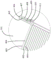
As shown in fig. 1 to 4, the present invention is explained in detail, and for convenience of description, the following orientations are defined as follows: the carsickness buffer device for the new energy automobile comprises a top plate 101, wherein at least four supporting and fixing devices 950 which are arranged in an annular array and used for supporting the top plate 101 are arranged in the top plate 101, unwinding devices 951 for putting plastic bags into the plastic are arranged on the upper end face of the top plate 101 in an array mode, and foreign matter prevention devices 952 which are located in the top plate 101 and used for preventing foreign matters from entering the device are arranged between the unwinding devices 951 for the plastic bags.
Advantageously, wherein the supporting fixture 950 comprises a rotation cavity 202 disposed in the top plate 101, the rotation cavity 202 is open, a rotation block 203 is rotatably disposed in the rotation cavity 202, the width of the rotation block 203 is the same as the width of the rotation cavity 202, symmetrical rods 204 are fixedly disposed on the end surface of the rotation block 203 far away from the rotation cavity 202, the length of the symmetrical rod 204 is at least 10cm, the end face of the symmetrical rod 204 far away from the rotating block 203 is fixedly provided with a bottom block 205, the bottom block 205 is of a rectangular structure, the side length of the bottom block 205 is larger than the diameter of the symmetrical rod 204, an inner rotating block 206 is rotatably arranged between the bottom blocks 205, the end face of the inner rotating block 206 far away from the bottom block 205 is fixedly provided with a round rod 210, the height of the round rod 210 is at least 0.6m, the lower end face of the round rod 210 is fixedly provided with a bottom supporting plate 212, and an adjusting component for adjusting the height of the top plate 101 is arranged between the round rod 210 and the top plate 101, so that the height of the top plate 101 is.
Advantageously, the adjusting assembly comprises a sliding housing 209 connected with the round rod 210 in a sliding fit manner, a connecting rod 207 is rotatably arranged in the sliding housing 209, the connecting rod 207 is connected with the rotating block 203 in a rotating fit manner, the length of the connecting rod 207 is at least 8cm, a locking screw 208 is arranged in the sliding housing 209, and the locking screw 208 locks the sliding housing 209 on the outer surface of the round rod 210 in a threaded fit manner, so that the connecting rod 207 is swung by lifting and lowering the sliding housing 209, and the symmetrical rod 204 is swung, and the height of the top plate 101 is changed.
Advantageously, the unwinding device 951 of plastic comprises a bottom-opening cavity 301 disposed in the top plate 101 and penetrating up and down, and a plastic bag discharging assembly for discharging plastic bags is disposed above the bottom-opening cavity 301, so that the plastic bag discharging assembly is used for discharging the plastic bags for car-sick people.
Beneficially, the plastic bag discharging assembly includes a bottom casing 221 disposed above the bottom-opened inner cavity 301 and fixed to the top plate 101, a top-opened cavity 224 penetrating through the bottom casing 221 from top to bottom is disposed in the bottom casing 221, a closed frame 222 is fixedly disposed on an upper end surface of the bottom casing 221, the closed frame 222 and the bottom casing 221 are fixedly coupled by bolts, the closed frame 222 is of a frame structure, the closed frame 222 and the bottom casing 221 have the same size, a winding drum 223 is rotatably disposed in the closed frame 222 and the top-opened cavity 224, the winding drum 223 is driven to rotate by a driving structure disposed on a front side of the bottom casing 221, a plurality of plastic bag structures are wound on an outer surface of the winding drum 223, and thus the driving structure is used to drive the winding drum 223 to rotate so as.
Advantageously, the driving structure comprises a bottom plate 219 fixed on one side of the bottom housing 221, a driving motor 218 is fixed on the upper end surface of the bottom plate 219, a rotating column 220 is disposed in the driving motor 218 in a power connection manner, and the rotating column 220 is in power connection with the winding drum 223, so that the driving motor 218 is used for driving the rotating column 220 to rotate to enable the winding drum 223 to rotate, and then the plastic bag structure is unwound.
Beneficially, wherein, the plastic bag structure includes a plurality of bag bodies 217 arranged on the outer surface of the winding drum 223, the bag bodies 217 are cooperatively connected through the connecting blocks 211, an open accommodating cavity 216 is arranged in the bag body 217, the depth of the accommodating cavity 216 is at least 25cm, open folding cavities 214 are arranged on the front and rear end surfaces of the bag body 217, and handles 215 which are fixed with the bag body 217 and are bilaterally symmetrical are arranged above the folding cavities 214, so that the accommodating cavity 216 is used by people and the bag body 217 can be torn down at any time.
Beneficially, the foreign object prevention device 952 includes a through cavity 403 disposed in the top plate 101, the through cavity 403 is disposed to penetrate up and down, a limiting frame 102 fixed to the top plate 101 and disposed in an array is disposed above the through cavity 403, the limiting frame 102 is of a frame structure, a portion of the limiting frame 102 is exposed above the through cavity 403, and a guardrail assembly for preventing foreign objects in an external space from entering the vehicle is disposed in the through cavity 403, so that the guardrail assembly is used for preventing foreign objects outside the vehicle from entering the vehicle.
Beneficially, wherein, the guardrail subassembly includes the roof-rack 404 of being connected with punch-through chamber 403 dress card cooperation, be provided with the chamber 401 that runs through from top to bottom in the roof-rack 404, set firmly a plurality of horizontal poles 402 in the chamber 401, the length of horizontal pole 402 is 0.6m at least, roof-rack 404 with offset, punch-through chamber 403 is provided with all around and is located a plurality of tight structures in top of restricting roof-rack 404 in punch-through chamber 403 under the roof 101, tight structure in top is provided with four at least to utilize tight structure in top to restrict roof-rack 404 in punch-through chamber 403.
Beneficially, the jacking structure comprises a mounting shell 407 fixed with the top plate 101, an open inner sliding cavity 408 is formed in the mounting shell 407, an outer threaded shaft 405 is rotatably arranged between end walls of the inner sliding cavity 408, the length of the outer threaded shaft 405 is longer than that of the inner sliding cavity 408, a disc 406 is fixedly arranged on the end face, far away from the through cavity 403, of the outer threaded shaft 405, the diameter of the disc 406 is at least 4cm, a moving block 409 is slidably arranged in the inner sliding cavity 408, the moving block 409 is in threaded fit connection with the outer threaded shaft 405, a side connecting rod 410 is rotatably arranged in the moving block 409, a turnover top plate 411 is rotatably arranged in the side connecting rod 410, the turnover top plate 411 is in rotatable fit connection with the mounting shell 407, the turnover top plate 411 abuts against the top frame 404, the bending angle of the turnover top, therefore, moving block 409 moves to drive side connecting rod 410 to swing, and turnover top plate 411 swings to clamp top frame 404 in through cavity 403.
In an initial state, the above devices, assemblies and structures are in a stop working state, the devices need to be installed in a vehicle before the devices work, a bottom support plate 212 and a round rod 210 are respectively placed at the four corners in the vehicle without influencing the driving and riding of people, at this time, the distance between the top plate 101 and the top of the vehicle is adjusted in advance, a locking screw 208 is rotated to enable the locking screw 208 to be separated from a sliding shell 209 and the round rod 210 to be locked and fixed, after the sliding shell 209 is slid, the sliding shell 209 is moved to drive a connecting rod 207 to rotate, at this time, as the connecting rod 207 is connected with the rotating block 203 in a rotating matching manner, a symmetrical rod 204, the rotating block 203 and a bottom block 205 are rotated relative to an inner rotating block 206 to enable the height of the top plate 101 to be changed, after the adjustment is finished, the locking screw 208 is installed in the sliding shell 209 again to enable the locking screw 208 to lock and fix, the top frame 404 is clamped in the through cavity 403, and shields sundries outside the automobile on the lower side of the automobile skylight, so that the automobile can be ventilated, and meanwhile, sundries in an external space cannot enter the automobile.
When people have carsickness and the like, the plastic bag needs to be used, the driving motor 218 drives the rotating column 220 to rotate after working at the moment, the rotating column 220 drives the winding drum 223 to rotate, the winding drum 223 rotates to enable the bag body 217 to be discharged downwards, the people can use the bag body 217 after directly tearing off the bag body 217 at the moment, the connecting blocks 211 are of a connecting structure, and the connecting blocks 211 are broken and separated after tearing off the bag body 217.
When the top frame 404 needs to be disassembled, the disc 406 is rotated, the disc 406 rotates to drive the external threaded shaft 405 to rotate, the external threaded shaft 405 rotates to drive the moving block 409 to move, the moving block 409 drives the side connecting rod 410 to swing, the overturning top plate 411 swings and then is separated from the support of the top frame 404, and at the moment, the top frame 404 is disassembled to be replaced.
The invention has the beneficial effects that: this equipment has adopted the unwinding device 951 and the foreign matter prevention device 952 that support fixing device 950, plastics, has realized that can be automatic carry out the plastic bag and unreel the process, makes personnel can in time use the plastic bag, and can not make outside debris enter into the car from the exterior space under the circumstances of guaranteeing that the vehicle ventilates.
The advantages are expressed in that the sliding shell 209 and the round rod 210 are locked by the locking screw 208, the structure formed by the connecting rod 207, the symmetrical rod 204, the inner rotating block 206 and the round rod 210 tends to be stable, the design of the locking screw 208 can save materials and ensure the round rod 210 and the sliding shell 209 to be indirectly fixed, the structure of the connecting rod 207, the symmetrical rod 204, the inner rotating block 206, the locking screw 208 and the round rod 210 is utilized to enable the top plate 101 to have height adjustability, the installation and adjustment are more convenient during actual use, the driving motor 218 is utilized to indirectly drive the winding drum 223 to rotate so as to enable the bag body 217 to be unreeled, the bag body 217 can be rapidly pulled down for use by personnel, the bag body 217 can be supplemented in time, the personnel use time also has the advantage of being convenient, the design of the folding cavity 214 enables the bag body 217 to be better coated on the outer surface of the winding drum 223 when being rolled, and the design of the handle 215, so that personnel use, utilize the design of connecting block 211, make personnel can tear down the bag body 217 fast, utilize appearance chamber 401 in the roof-rack 404 to fully shelter from the debris of exterior space, and make the roof-rack 404 have and not influence under the condition of vehicle ventilation, block the debris outside the vehicle skylight, very big improvement the reliability of equipment, utilize the bending design of upset roof 411, make the upset roof 411 can be fixed in wearing to lead to the chamber 403 with the better restriction of roof-rack 404 under the drive of side connecting rod 410, and be convenient for upset roof 411 break away from fixedly with the counterbalance of roof-rack 404.
The specific embodiments described herein are merely illustrative of the spirit of the invention. Various modifications or additions may be made to the described embodiments or alternatives may be employed by those skilled in the art without departing from the spirit or ambit of the invention as defined in the appended claims.
Although terms such as the top plate 101, the limiting frame 102, the rotating cavity 202, the rotating block 203, the symmetric rod 204, the bottom block 205, the inner rotating block 206, the connecting rod 207, the locking screw 208, the sliding housing 209, the round rod 210, the connecting block 211, the bottom supporting plate 212, the folding cavity 214, the handle 215, the accommodating cavity 216, the bag 217, the driving motor 218, the bottom plate 219, the rotating column 220, the bottom housing 221, the closed frame 222, the winding drum 223, the top opening cavity 224, the bottom opening cavity 301, the accommodating cavity 401, the cross rod 402, the through cavity 403, the top frame 404, the external threaded shaft 405, the disk 406, the mounting housing 407, the inner sliding cavity 408, the moving block 409, the side connecting rod 410, the flip top plate 411, the supporting and fixing device 950, the plastic unwinding device 951, the foreign object preventing device 952, and the like are used more frequently, the possibility of using other terms is. These terms are used merely to more conveniently describe and explain the nature of the present invention and they are to be interpreted as any additional limitation which is not in accordance with the spirit of the present invention.