CN110883841A - Die-cut frame - Google Patents
Die-cut frame Download PDFInfo
- Publication number
- CN110883841A CN110883841A CN201911023073.1A CN201911023073A CN110883841A CN 110883841 A CN110883841 A CN 110883841A CN 201911023073 A CN201911023073 A CN 201911023073A CN 110883841 A CN110883841 A CN 110883841A
- Authority
- CN
- China
- Prior art keywords
- bottom plate
- plate
- die
- cutting
- assembly
- Prior art date
- Legal status (The legal status is an assumption and is not a legal conclusion. Google has not performed a legal analysis and makes no representation as to the accuracy of the status listed.)
- Pending
Links
Images


Classifications
-
- B—PERFORMING OPERATIONS; TRANSPORTING
- B26—HAND CUTTING TOOLS; CUTTING; SEVERING
- B26D—CUTTING; DETAILS COMMON TO MACHINES FOR PERFORATING, PUNCHING, CUTTING-OUT, STAMPING-OUT OR SEVERING
- B26D7/00—Details of apparatus for cutting, cutting-out, stamping-out, punching, perforating, or severing by means other than cutting
- B26D7/26—Means for mounting or adjusting the cutting member; Means for adjusting the stroke of the cutting member
-
- B—PERFORMING OPERATIONS; TRANSPORTING
- B26—HAND CUTTING TOOLS; CUTTING; SEVERING
- B26F—PERFORATING; PUNCHING; CUTTING-OUT; STAMPING-OUT; SEVERING BY MEANS OTHER THAN CUTTING
- B26F1/00—Perforating; Punching; Cutting-out; Stamping-out; Apparatus therefor
- B26F1/38—Cutting-out; Stamping-out
-
- B—PERFORMING OPERATIONS; TRANSPORTING
- B26—HAND CUTTING TOOLS; CUTTING; SEVERING
- B26D—CUTTING; DETAILS COMMON TO MACHINES FOR PERFORATING, PUNCHING, CUTTING-OUT, STAMPING-OUT OR SEVERING
- B26D7/00—Details of apparatus for cutting, cutting-out, stamping-out, punching, perforating, or severing by means other than cutting
- B26D7/26—Means for mounting or adjusting the cutting member; Means for adjusting the stroke of the cutting member
- B26D2007/2607—Means for mounting or adjusting the cutting member; Means for adjusting the stroke of the cutting member for mounting die cutters
Landscapes
- Life Sciences & Earth Sciences (AREA)
- Forests & Forestry (AREA)
- Engineering & Computer Science (AREA)
- Mechanical Engineering (AREA)
- Perforating, Stamping-Out Or Severing By Means Other Than Cutting (AREA)
Abstract
本发明提供了一种模切版框,所述模切版框包括底板组件和侧板组件,所述底板组件包括第一底板、第二底板和第三底板,所述第一底板、第二底板和第三底板依次从上至下堆叠,第二底板的底面与第三底板的顶面贴合,第一底板的底面与第二底板的顶面贴合,所述底板组件与侧板组件的底边连接,侧板组件围绕在底板组件的四周,所述底板组件和侧板组件之间的空间形成用于安装模切刀板和垫板安装和安装槽。本发明的优点在于:通过材质软硬不同减少了对垫板和刀板的磨损,提高了垫板和刀板的耐用度;减轻了了由于刀版加工、机器零件加工造成的平面度和压力不一致的问题,减少了进行补压操作的频率;底板可拆卸,便于更换。
The present invention provides a die-cutting plate frame, the die-cutting plate frame includes a bottom plate assembly and a side plate assembly, the bottom plate assembly includes a first bottom plate, a second bottom plate and a third bottom plate, the first bottom plate, the second bottom plate The bottom plate and the third bottom plate are stacked sequentially from top to bottom, the bottom surface of the second bottom plate is attached to the top surface of the third bottom plate, the bottom surface of the first bottom plate is attached to the top surface of the second bottom plate, and the bottom plate assembly and the side plate assembly are attached. The bottom edge is connected, the side plate assembly surrounds the bottom plate assembly, and the space between the bottom plate assembly and the side plate assembly forms an installation and installation groove for installing the die-cutting blade and the backing plate. The advantages of the invention are: the wear of the backing plate and the cutting board is reduced by the different soft and hard materials, the durability of the backing board and the cutting board is improved; the flatness and pressure caused by the processing of the cutting board and the processing of machine parts are reduced. The problem of inconsistency reduces the frequency of making up pressure operations; the bottom plate is removable for easy replacement.
Description
技术领域technical field
本发明涉及一种模切装置,具体是涉及一种模切版框。The invention relates to a die-cutting device, in particular to a die-cutting plate frame.
背景技术Background technique
随着印刷包装行业的快速发展,市场对印后加工设备自动化程度的要求越来越高,追求高速精准的加工设备,用以提高生产效率从而占领市场是巿场需求也是印后设备的发展必然趋势。模切机是一种用于印刷、包装装潢行业的纸张、纸板和瓦楞纸的压痕及模切加工的专用设备。With the rapid development of the printing and packaging industry, the market has higher and higher requirements for the degree of automation of post-press processing equipment. The pursuit of high-speed and accurate processing equipment to improve production efficiency and occupy the market is the market demand and the inevitable development of post-press equipment. trend. Die-cutting machine is a special equipment used for indentation and die-cutting of paper, cardboard and corrugated paper in the printing, packaging and decoration industries.
现有的模切机包括上模切版和下垫板,上模切版的模切刀板与模切版框之间为硬接触,当模切刀板的模切刀在制作过程中产生的高低误差与模切版框的平面度造成的误差,都会导致机器在模切生产过程中产生压力不平均,不一致的现象。这就需要操作工使用专门的补压纸对机器压力偏低的地方进行补压,直到将压力补到一致为止,而且更换一款产品之后还需要根据那款产品的刀板情况重新进行补压。有些上模切版会使用垫板来减轻压力不平均的问题,因为垫板的硬度一般较低,钢制模切版框会对垫板造成较大的磨损。The existing die-cutting machine includes an upper die-cutting plate and a lower backing plate. There is a hard contact between the die-cutting blade of the upper die-cutting plate and the die-cutting plate frame. The height error of the die-cutting plate frame and the flatness of the die-cutting frame will cause the machine to produce uneven and inconsistent pressure during the die-cutting production process. This requires the operator to use special pressurizing paper to pressurize the places where the pressure of the machine is low until the pressure is consistent, and after replacing a product, it is necessary to re-pressurize according to the condition of the blade of that product . Some upper die-cutting plates will use a backing plate to alleviate the problem of uneven pressure, because the hardness of the backing plate is generally low, and the steel die-cutting plate frame will cause greater wear on the backing plate.
综上所述,需要提供涉及一种模切版框,其能够克服现有技术的缺陷。In conclusion, there is a need to provide a die-cutting plate frame which can overcome the defects of the prior art.
发明内容SUMMARY OF THE INVENTION
本发明旨在提供涉及一种模切版框,其能够克服现有技术的缺陷。本发明的发明目的通过以下技术方案得以实现。The present invention aims to provide a die-cutting plate frame, which can overcome the defects of the prior art. The purpose of the present invention is achieved through the following technical solutions.
本发明的一个实施方式提供了一种模切版框,所述模切版框包括底板组件和侧板组件,所述底板组件包括第一底板、第二底板和第三底板,所述第一底板、第二底板和第三底板依次从上至下堆叠,第二底板的底面与第三底板的顶面贴合,第一底板的底面与第二底板的顶面贴合,所述底板组件与侧板组件的底边连接,侧板组件围绕在底板组件的四周,所述底板组件和侧板组件之间的空间形成用于安装模切刀板和垫板安装和安装槽。One embodiment of the present invention provides a die-cutting plate frame, the die-cutting plate frame includes a bottom plate assembly and a side plate assembly, the bottom plate assembly includes a first bottom plate, a second bottom plate and a third bottom plate, the first bottom plate The bottom plate, the second bottom plate and the third bottom plate are stacked sequentially from top to bottom. It is connected with the bottom edge of the side plate assembly, the side plate assembly surrounds the bottom plate assembly, and the space between the bottom plate assembly and the side plate assembly forms an installation and installation groove for installing the die-cutting blade and the backing plate.
根据本发明的上述一个实施方式所述的模切版框,其中所述第一底板的硬度低于第二底板的硬度,第二底板的硬度低于第三底板的硬度,所述第三底板为钢板。According to the above-mentioned one embodiment of the present invention, the die-cutting plate frame, wherein the hardness of the first base plate is lower than that of the second base plate, and the hardness of the second base plate is lower than that of the third base plate, and the third base plate has a hardness lower than that of the third base plate. for steel plate.
根据本发明的上述一个实施方式所述的模切版框,其中所述第一底板的硬度范围为:60-110HV,第二底板的硬度范围为:340-400HV。According to the die-cutting plate frame according to the above-mentioned one embodiment of the present invention, the hardness range of the first base plate is: 60-110HV, and the hardness range of the second base plate is: 340-400HV.
根据本发明的上述一个实施方式所述的模切版框,其中所述侧板组件包括第一侧板、第二侧板和两个第三侧板,所述两个第三侧板的低边分别与底板组件相对的两边连接,第一侧板的低边与底板组件的第三边连接,第二侧板的低边与和底板组件的第三边相对的底板组件的第四边连接,第一侧板的两端分别与两个第三侧板位于同一侧的侧边连接,第二侧板的两端分别与两个第三侧板位于另一侧的侧边连接。The die-cutting plate frame according to the above-mentioned one embodiment of the present invention, wherein the side plate assembly includes a first side plate, a second side plate and two third side plates, and the lower The sides are respectively connected with the two opposite sides of the bottom plate assembly, the low side of the first side plate is connected with the third side of the bottom plate assembly, the low side of the second side plate is connected with the fourth side of the bottom plate assembly opposite to the third side of the bottom plate assembly The two ends of the first side plate are respectively connected with the sides of the two third side plates on the same side, and the two ends of the second side plate are respectively connected with the sides of the two third side plates on the other side.
根据本发明的上述一个实施方式所述的模切版框,其中所述模切版框还包括多个夹紧块,所述第一侧板、第二侧板和两个第三侧板顶部靠近安装槽的一侧分别设置有夹紧块,所述多个夹紧块共同将模切刀板固定在安装槽内。The die-cutting plate frame according to the above-mentioned one embodiment of the present invention, wherein the die-cutting plate frame further comprises a plurality of clamping blocks, the tops of the first side plate, the second side plate and the two third side plates Clamping blocks are respectively provided on one side close to the installation groove, and the plurality of clamping blocks jointly fix the die-cutting blade in the installation groove.
根据本发明的上述一个实施方式所述的模切版框,其中所述第一底板、第二底板和第三底板之间通过螺钉固定连接。According to the die-cutting plate frame according to the above-mentioned one embodiment of the present invention, the first bottom plate, the second bottom plate and the third bottom plate are fixedly connected by screws.
根据本发明的上述一个实施方式所述的模切版框,其中所述底板组件和侧板组件之间通过螺钉固定连接。According to the die-cutting plate frame according to the above-mentioned one embodiment of the present invention, the bottom plate assembly and the side plate assembly are fixedly connected by screws.
根据本发明的上述一个实施方式所述的模切版框,其中所述模切版框还包括两个把手和连接件,两个把手和连接件固定安装在第一侧板的外侧,连接件位于第一侧板外侧的中部,两个把手分别位于连接件的左右两侧。The die-cutting plate frame according to the above-mentioned one embodiment of the present invention, wherein the die-cutting plate frame further comprises two handles and connecting pieces, the two handles and the connecting pieces are fixedly installed on the outer side of the first side plate, and the connecting pieces Located in the middle of the outer side of the first side plate, the two handles are respectively located on the left and right sides of the connecting piece.
该模切版框的优点在于:通过材质软硬不同减少了对垫板和刀板的磨损,提高了垫板和刀板的耐用度;减轻了了由于刀版加工、机器零件加工造成的平面度和压力不一致的问题,减少了进行补压操作的频率;底板可拆卸,便于更换。The advantages of the die-cutting plate frame are: the wear of the backing plate and the blade is reduced by the different hardness and softness of the material, and the durability of the backing plate and the blade is improved; the plane caused by the processing of the blade and machine parts is reduced. The problem of inconsistency of degree and pressure reduces the frequency of pressure compensation operation; the bottom plate can be disassembled for easy replacement.
附图说明Description of drawings
参照附图,本发明的公开内容将变得更易理解。本领域技术人员容易理解的是:这些附图仅仅用于举例说明本发明的技术方案,而并非意在对本发明的保护范围构成限制。图中:The disclosure of the present invention will become more easily understood with reference to the accompanying drawings. Those skilled in the art can easily understand that these drawings are only used to illustrate the technical solutions of the present invention, and are not intended to limit the protection scope of the present invention. In the picture:
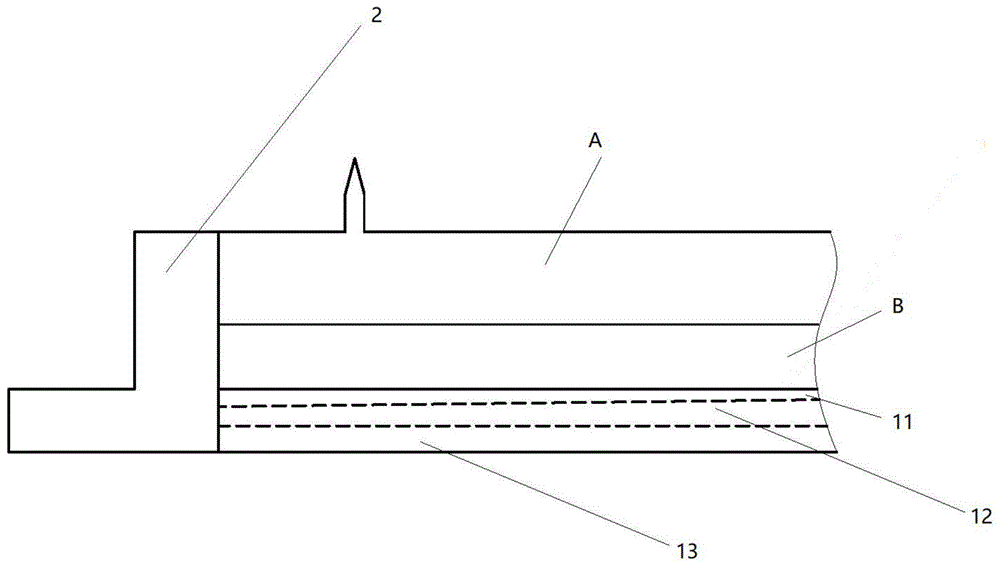
图1是根据本发明一个实施方式的安装了模切刀板和垫板的模切版框的剖面图;1 is a cross-sectional view of a die-cutting plate frame with a die-cutting blade and a backing plate installed according to an embodiment of the present invention;
图2示出了如图1所示的根据本发明一个实施方式的包括了模切刀板的模切版框的立体图;FIG. 2 shows a perspective view of a die-cutting plate frame including a die-cutting blade according to an embodiment of the present invention as shown in FIG. 1;
图3示出了如图1所示的根据本发明一个实施方式的安装了模切刀板的模切版框的立体图。FIG. 3 shows a perspective view of a die-cutting plate frame with a die-cutting blade installed according to an embodiment of the present invention as shown in FIG. 1 .
具体实施方式Detailed ways
图1-3和以下说明描述了本发明的可选实施方式以教导本领域技术人员如何实施和再现本发明。为了教导本发明技术方案,已简化或省略了一些常规方面。本领域技术人员应该理解源自这些实施方式的变型或替换将落在本发明的保护范围内。本领域技术人员应该理解下述特征能够以各种方式组合以形成本发明的多个变型。由此,本发明并不局限于下述可选实施方式,而仅由权利要求和它们的等同物限定。Figures 1-3 and the following description describe alternative embodiments of the invention to teach those skilled in the art how to implement and reproduce the invention. In order to teach the technical solutions of the present invention, some conventional aspects have been simplified or omitted. Those skilled in the art will appreciate that modifications or substitutions derived from these embodiments will fall within the scope of the present invention. Those skilled in the art will appreciate that the following features can be combined in various ways to form various variations of the invention. Thus, the present invention is not limited to the alternative embodiments described below, but only by the claims and their equivalents.
如图1-3所示本发明的一个实施方式提供了一种模切版框,所述模切版框包括底板组件1和侧板组件2,所述底板组件1包括第一底板11、第二底板12和第三底板13,所述第一底板11、第二底板12和第三底板13依次从上至下堆叠,第二底板12的底面与第三底板13的顶面贴合,第一底板11的底面与第二底板12的顶面贴合,所述底板组件1与侧板组件2的底边连接,侧板组件2围绕在底板组件1的四周,所述底板组件1和侧板组件2之间的空间形成安装槽,所述安装槽用于安装单独的模切刀板A或者用于同时安装模切刀板A和垫板B。As shown in Figures 1-3, an embodiment of the present invention provides a die-cutting plate frame, the die-cutting plate frame includes a
根据本发明的上述一个实施方式所述的模切版框,其中所述第一底板11的硬度低于第二底板12的硬度,第二底板12的硬度低于第三底板13的硬度,所述第三底板13为钢板。According to the die-cutting plate frame according to the above-mentioned one embodiment of the present invention, the hardness of the
根据本发明的上述一个实施方式所述的模切版框,其中所述第一底板11的硬度范围为:60-110HV,第二底板12的硬度范围为:340-400HV。According to the die-cutting plate frame according to the above-mentioned one embodiment of the present invention, the hardness range of the
根据本发明的上述一个实施方式所述的模切版框,其中所述侧板组件2包括第一侧板21、第二侧板22和两个第三侧板23,所述两个第三侧板23的低边分别与底板组件1相对的两边连接,第一侧板21的低边与底板组件1的第三边连接,第二侧板22的低边与和底板组件1的第三边相对的底板组件1的第四边连接,第一侧板21的两端分别与两个第三侧板23位于同一侧的侧边连接,第二侧板22的两端分别与两个第三侧板23位于另一侧的侧边连接。According to the die-cutting plate frame according to the above-mentioned one embodiment of the present invention, the
根据本发明的上述一个实施方式所述的模切版框,其中所述模切版框还包括多个夹紧块6,所述第一侧板21、第二侧板22和两个第三侧板23顶部靠近安装槽的一侧分别设置有夹紧块6,所述多个夹紧块6共同将垫板B和模切刀板A固定在安装槽内。The die-cutting plate frame according to the above-mentioned one embodiment of the present invention, wherein the die-cutting plate frame further comprises a plurality of
根据本发明的上述一个实施方式所述的模切版框,其中所述第一底板11、第二底板12和第三底板13之间通过螺钉固定连接。According to the die-cutting plate frame according to the above-mentioned one embodiment of the present invention, the
根据本发明的上述一个实施方式所述的模切版框,其中所述底板组件1和侧板组件2之间通过螺钉固定连接。According to the die-cutting plate frame according to the above-mentioned one embodiment of the present invention, the
根据本发明的上述一个实施方式所述的模切版框,其中所述模切版框还包括两个把手4和连接件5,两个把手4和连接件5固定安装在第一侧板21的外侧,连接件5位于第一侧板21外侧的中部,两个把手4分别位于连接件5的左右两侧。把手4用于搬运模切版框,连接件5用于将模切版框固定连接至模切机上。According to the die-cutting plate frame according to the above-mentioned one embodiment of the present invention, the die-cutting plate frame further comprises two
该模切版框的优点在于:通过材质软硬不同减少了对垫板和刀板的磨损,提高了垫板和刀板的耐用度;减轻了了由于刀版加工、机器零件加工造成的平面度和压力不一致的问题,减少了进行补压操作的频率;底板可拆卸,便于更换。The advantages of the die-cutting plate frame are: the wear of the backing plate and the blade is reduced by the different hardness and softness of the material, and the durability of the backing plate and the blade is improved; the plane caused by the processing of the blade and machine parts is reduced. The problem of inconsistency of degree and pressure reduces the frequency of pressure compensation operation; the bottom plate can be disassembled for easy replacement.
以上所述,仅为本发明较佳具体实施方式,但本发明的保护范围并不局限于此,任何熟悉本技术领域的技术人员在本发明所揭露的技术范围内,可轻易想到的变化或替代,都应涵盖在本发明的保护范围之内。The above is only the preferred embodiment of the present invention, but the protection scope of the present invention is not limited to this. Alternatives should be included within the protection scope of the present invention.
Claims (8)
Priority Applications (1)
| Application Number | Priority Date | Filing Date | Title |
|---|---|---|---|
| CN201911023073.1A CN110883841A (en) | 2019-10-25 | 2019-10-25 | Die-cut frame |
Applications Claiming Priority (1)
| Application Number | Priority Date | Filing Date | Title |
|---|---|---|---|
| CN201911023073.1A CN110883841A (en) | 2019-10-25 | 2019-10-25 | Die-cut frame |
Publications (1)
| Publication Number | Publication Date |
|---|---|
| CN110883841A true CN110883841A (en) | 2020-03-17 |
Family
ID=69746436
Family Applications (1)
| Application Number | Title | Priority Date | Filing Date |
|---|---|---|---|
| CN201911023073.1A Pending CN110883841A (en) | 2019-10-25 | 2019-10-25 | Die-cut frame |
Country Status (1)
| Country | Link |
|---|---|
| CN (1) | CN110883841A (en) |
Cited By (1)
| Publication number | Priority date | Publication date | Assignee | Title |
|---|---|---|---|---|
| CN114654811A (en) * | 2020-12-22 | 2022-06-24 | 天津长荣科技集团股份有限公司 | Lower backing plate |
Citations (5)
| Publication number | Priority date | Publication date | Assignee | Title |
|---|---|---|---|---|
| CN201783986U (en) * | 2010-07-30 | 2011-04-06 | 深圳市石化印刷有限公司 | Die cutting board structure |
| CN202952321U (en) * | 2012-11-22 | 2013-05-29 | 粤和兴激光刀模(深圳)有限公司 | Resin cutting die with adjustable intervals |
| CN204054210U (en) * | 2014-08-15 | 2014-12-31 | 武汉华森塑胶有限公司 | Cut Self-enclosing cutting die |
| CN108943146A (en) * | 2018-09-29 | 2018-12-07 | 天津长荣科技集团股份有限公司 | Upper die cutting plate |
| CN211333507U (en) * | 2019-10-25 | 2020-08-25 | 天津长荣科技集团股份有限公司 | Die cutting chase |
-
2019
- 2019-10-25 CN CN201911023073.1A patent/CN110883841A/en active Pending
Patent Citations (5)
| Publication number | Priority date | Publication date | Assignee | Title |
|---|---|---|---|---|
| CN201783986U (en) * | 2010-07-30 | 2011-04-06 | 深圳市石化印刷有限公司 | Die cutting board structure |
| CN202952321U (en) * | 2012-11-22 | 2013-05-29 | 粤和兴激光刀模(深圳)有限公司 | Resin cutting die with adjustable intervals |
| CN204054210U (en) * | 2014-08-15 | 2014-12-31 | 武汉华森塑胶有限公司 | Cut Self-enclosing cutting die |
| CN108943146A (en) * | 2018-09-29 | 2018-12-07 | 天津长荣科技集团股份有限公司 | Upper die cutting plate |
| CN211333507U (en) * | 2019-10-25 | 2020-08-25 | 天津长荣科技集团股份有限公司 | Die cutting chase |
Cited By (2)
| Publication number | Priority date | Publication date | Assignee | Title |
|---|---|---|---|---|
| CN114654811A (en) * | 2020-12-22 | 2022-06-24 | 天津长荣科技集团股份有限公司 | Lower backing plate |
| CN114654811B (en) * | 2020-12-22 | 2025-08-15 | 天津长荣科技集团股份有限公司 | Lower backing plate |
Similar Documents
| Publication | Publication Date | Title |
|---|---|---|
| CN102120328B (en) | Sandwich type cutting die with honeycomb structure | |
| US20180154602A1 (en) | 3D Printed Paperboard Creasing/Cutting Rule | |
| JP2010284866A (en) | Ruled line forming tool | |
| CN110883841A (en) | Die-cut frame | |
| CN211333507U (en) | Die cutting chase | |
| CN208196537U (en) | Grinding machine vacuum adsorption fixture | |
| KR20090008926A (en) | Wood mold structure with spring cushion material | |
| CN108943146B (en) | Upper die cutting plate | |
| CN108943147B (en) | Lower backing plate of die cutting machine | |
| CN111216198A (en) | Upper die-cutting plate of die-cutting machine | |
| CN201304667Y (en) | Chopping board improvement of punching plastic floor | |
| JP6315531B1 (en) | Female die for punching machine and punching machine | |
| CN211164298U (en) | Flat-pressing die-cutting machine | |
| KR20080107741A (en) | Lightweight wood mold | |
| CN211490553U (en) | Processing jig for notebook computer parts | |
| CN211889913U (en) | CNC machining device for 3C product parts | |
| CN211490550U (en) | CNC precision machining equipment for electronic product accessories | |
| CN115464920A (en) | Universal tool bit for spacer bender | |
| CN208801454U (en) | Upper die cutting plate | |
| CN217256843U (en) | Carton hard board cuts and uses die set | |
| KR100563625B1 (en) | How to make puzzle | |
| KR100644090B1 (en) | Wood mold with magnet | |
| CN222366439U (en) | A PCBA fixing device for preventing force displacement | |
| JP2018051729A (en) | Trimming die | |
| US20070028743A1 (en) | Device for punching packaging elements or the like |
Legal Events
| Date | Code | Title | Description |
|---|---|---|---|
| PB01 | Publication | ||
| PB01 | Publication | ||
| SE01 | Entry into force of request for substantive examination | ||
| SE01 | Entry into force of request for substantive examination | ||
| WD01 | Invention patent application deemed withdrawn after publication | ||
| WD01 | Invention patent application deemed withdrawn after publication |
Application publication date: 20200317 |