CN110843749B - An automobile drive shaft with preventing misoperation - Google Patents
An automobile drive shaft with preventing misoperation Download PDFInfo
- Publication number
- CN110843749B CN110843749B CN201911210725.2A CN201911210725A CN110843749B CN 110843749 B CN110843749 B CN 110843749B CN 201911210725 A CN201911210725 A CN 201911210725A CN 110843749 B CN110843749 B CN 110843749B
- Authority
- CN
- China
- Prior art keywords
- input
- output
- oil
- cavity
- shaft group
- Prior art date
- Legal status (The legal status is an assumption and is not a legal conclusion. Google has not performed a legal analysis and makes no representation as to the accuracy of the status listed.)
- Expired - Fee Related
Links
Images


Classifications
-
- B—PERFORMING OPERATIONS; TRANSPORTING
- B60—VEHICLES IN GENERAL
- B60T—VEHICLE BRAKE CONTROL SYSTEMS OR PARTS THEREOF; BRAKE CONTROL SYSTEMS OR PARTS THEREOF, IN GENERAL; ARRANGEMENT OF BRAKING ELEMENTS ON VEHICLES IN GENERAL; PORTABLE DEVICES FOR PREVENTING UNWANTED MOVEMENT OF VEHICLES; VEHICLE MODIFICATIONS TO FACILITATE COOLING OF BRAKES
- B60T13/00—Transmitting braking action from initiating means to ultimate brake actuator with power assistance or drive; Brake systems incorporating such transmitting means, e.g. air-pressure brake systems
- B60T13/10—Transmitting braking action from initiating means to ultimate brake actuator with power assistance or drive; Brake systems incorporating such transmitting means, e.g. air-pressure brake systems with fluid assistance, drive, or release
- B60T13/12—Transmitting braking action from initiating means to ultimate brake actuator with power assistance or drive; Brake systems incorporating such transmitting means, e.g. air-pressure brake systems with fluid assistance, drive, or release the fluid being liquid
- B60T13/14—Transmitting braking action from initiating means to ultimate brake actuator with power assistance or drive; Brake systems incorporating such transmitting means, e.g. air-pressure brake systems with fluid assistance, drive, or release the fluid being liquid using accumulators or reservoirs fed by pumps
-
- B—PERFORMING OPERATIONS; TRANSPORTING
- B60—VEHICLES IN GENERAL
- B60T—VEHICLE BRAKE CONTROL SYSTEMS OR PARTS THEREOF; BRAKE CONTROL SYSTEMS OR PARTS THEREOF, IN GENERAL; ARRANGEMENT OF BRAKING ELEMENTS ON VEHICLES IN GENERAL; PORTABLE DEVICES FOR PREVENTING UNWANTED MOVEMENT OF VEHICLES; VEHICLE MODIFICATIONS TO FACILITATE COOLING OF BRAKES
- B60T7/00—Brake-action initiating means
- B60T7/12—Brake-action initiating means for automatic initiation; for initiation not subject to will of driver or passenger
- B60T7/22—Brake-action initiating means for automatic initiation; for initiation not subject to will of driver or passenger initiated by contact of vehicle, e.g. bumper, with an external object, e.g. another vehicle, or by means of contactless obstacle detectors mounted on the vehicle
Landscapes
- Engineering & Computer Science (AREA)
- Transportation (AREA)
- Mechanical Engineering (AREA)
- Actuator (AREA)
Abstract
本发明公开了一种具有防止误操作的汽车驱动轴,包括安装固定架、输出轴组、控制轴组和输入轴组,所述安装固定架上设置有安装板,所述安装板的底部两端侧壁上通过连接板连接有输出定位套和输入定位套,所述输出轴组的一端贯穿套设在输出定位套上,所述输入轴组的一端贯穿套设在输入定位套上。本发明是输入轴组上的输入滑套和输入定位套之间设置油腔,油腔内填充液压油,输入滑套外部的螺旋叶片旋转带动液压油通过回油管进行循环,当输入轴转速瞬间提高时,回油管来不及循环,液压油通过进油管进入到油缸内,油缸推程推动输出轴组上的输出三棱圆柱进入到空载腔内,这样就会使输出轴组和输入轴组断开连接,停止传递扭矩。
The invention discloses an automobile drive shaft with the function of preventing misoperation. An output locating sleeve and an input locating sleeve are connected to the end side wall through a connecting plate, one end of the output shaft group is sleeved on the output locating sleeve, and one end of the input shaft group is sleeved through the input locating sleeve. In the present invention, an oil cavity is arranged between the input sliding sleeve and the input positioning sleeve on the input shaft group, the oil cavity is filled with hydraulic oil, and the rotation of the spiral blade outside the input sliding sleeve drives the hydraulic oil to circulate through the oil return pipe. When it is raised, the oil return pipe is too late to circulate, and the hydraulic oil enters the oil cylinder through the oil inlet pipe, and the push stroke of the oil cylinder pushes the output triangular cylinder on the output shaft group into the empty cavity, which will cause the output shaft group and the input shaft group to break. Open the connection to stop transmitting torque.
Description
技术领域technical field
本发明涉及汽车技术领域,具体为一种具有防止误操作的汽车驱动轴。The present invention relates to the technical field of automobiles, in particular to an automobile drive shaft with preventing misoperation.
背景技术Background technique
汽车是出行比较舒适的代步工具,汽车的安全驾驶是目前外出的重中之重,而现在的交通事故中,有很大比例是驾驶人员的误操作造成,其后果不堪设想,比如:在行进中遇到突发事件,驾驶员来不及踩刹车,反而错踏油门踏板,导致事故加重;在机车起步时,对于驾驶技术不熟练的驾驶员,通常出现油门和刹车分辨错误,导致起步或倒车出现意外;因此本发明提供一种具有防止误操作的汽车驱动轴。Cars are a more comfortable means of transportation, and safe driving of cars is the top priority when going out. A large proportion of traffic accidents are caused by driver's misoperation, and the consequences are unimaginable. In the event of an emergency, the driver does not have time to step on the brake, but instead steps on the accelerator pedal by mistake, resulting in aggravation of the accident; when the locomotive starts, for the driver who is not skilled in driving, there is usually a wrong distinction between the accelerator and the brake, resulting in an accident when starting or reversing. ; Therefore, the present invention provides an automobile drive shaft with preventing misoperation.
发明内容SUMMARY OF THE INVENTION
本发明的目的在于提供一种具有防止误操作的汽车驱动轴,以解决上述背景技术中提出的问题。The purpose of the present invention is to provide an automobile drive shaft with preventing misoperation, so as to solve the problems raised in the above-mentioned background art.
为实现上述目的,本发明提供如下技术方案:To achieve the above object, the present invention provides the following technical solutions:
一种具有防止误操作的汽车驱动轴,包括安装固定架、输出轴组、控制轴组和输入轴组,所述安装固定架上设置有安装板,所述安装板的底部两端侧壁上通过连接板连接有输出定位套和输入定位套,所述输出轴组的一端贯穿套设在输出定位套上,所述输入轴组的一端贯穿套设在输入定位套上,所述输出轴组通过控制轴组和输入轴组连接,所述输出轴组上设置有输出轴和输出滑套,所述输出滑套内设设置有输出滑动腔和油缸,所述输出滑动腔的一端设置有空载腔,所述输出滑动腔的内侧壁位于空载腔的一侧均匀开设有输出滑槽,所述油缸设置在输出滑动腔的另一端,所述输入轴组上设置有输入轴和输入滑套,所述输入滑套内设置有输入滑动腔,所述输入滑动腔的内侧壁上均匀开设有输入滑槽,所述输入定位套内设置有油腔,所述输入滑套的外边侧位于油腔内焊接有螺旋叶片,所述输入定位套的一端外边侧设置有蓄能单向阀和排油管,所述蓄能单向阀的另一端连接有蓄能罐,所述蓄能罐的一端设置有压力阀,所述输出定位套的外边侧焊接有进油管,所述进油管通过管路和排油管连接,所述控制轴组上设置有输出三棱圆柱和输入三棱圆柱。An automobile drive shaft capable of preventing misoperation, comprising an installation fixing frame, an output shaft group, a control shaft group and an input shaft group; An output locating sleeve and an input locating sleeve are connected through the connecting plate, one end of the output shaft group is sleeved on the output locating sleeve, one end of the input shaft group is sleeved on the input locating sleeve, and the output shaft group is sleeved through the input locating sleeve. The control shaft group is connected with the input shaft group. The output shaft group is provided with an output shaft and an output sliding sleeve. The output sliding sleeve is provided with an output sliding cavity and an oil cylinder. One end of the output sliding cavity is provided with a hollow space. Loading cavity, the inner side wall of the output sliding cavity is located on one side of the empty-loading cavity and evenly has an output chute, the oil cylinder is arranged at the other end of the output sliding cavity, and the input shaft group is provided with an input shaft and an input sliding The input sliding sleeve is provided with an input sliding cavity, the inner side wall of the input sliding cavity is evenly provided with an input chute, the input positioning sleeve is provided with an oil cavity, and the outer side of the input sliding sleeve is located in A spiral blade is welded in the oil cavity, an energy storage check valve and an oil discharge pipe are arranged on the outer side of one end of the input positioning sleeve, and an energy storage tank is connected to the other end of the energy storage check valve. One end is provided with a pressure valve, an oil inlet pipe is welded on the outer side of the output positioning sleeve, the oil inlet pipe is connected by a pipeline and an oil discharge pipe, and an output triangular cylinder and an input triangular cylinder are arranged on the control shaft group.
作为本发明的一种优选实施方式,所述油缸上设置有驱动杆,所述驱动杆的一端延伸至输出三棱圆柱的侧壁上。As a preferred embodiment of the present invention, a driving rod is provided on the oil cylinder, and one end of the driving rod extends to the side wall of the output triangular prism.
作为本发明的一种优选实施方式,所述输入三棱圆柱的一侧设置有复位弹簧。As a preferred embodiment of the present invention, a return spring is provided on one side of the input triangular prism.
作为本发明的一种优选实施方式,所述输出滑套的外边侧均匀开设有油道,所述油道的一端通过管路和油缸连接,所述输出定位套的内侧壁开设有和油道相对应的环型槽,所述进油管和环型槽连通。As a preferred embodiment of the present invention, oil passages are evenly opened on the outer side of the output sliding sleeve, one end of the oil passage is connected to the oil cylinder through a pipeline, and an oil passage is opened on the inner side wall of the output positioning sleeve Corresponding to the annular groove, the oil inlet pipe communicates with the annular groove.
作为本发明的一种优选实施方式,所述输入定位套的外边侧设置和油腔连通的回油管。As a preferred embodiment of the present invention, an oil return pipe communicated with the oil cavity is provided on the outer side of the input positioning sleeve.
作为本发明的一种优选实施方式,所述输出三棱圆柱和输入三棱圆柱上设置有滑板,所述滑板内设置有回转轴,所述回转轴上套设有滚珠,所述滚珠与输出滑槽和输入滑槽相对应。As a preferred embodiment of the present invention, a sliding plate is arranged on the output triangular prism and the input triangular cylinder, a rotating shaft is arranged in the sliding plate, and a ball is sleeved on the rotating shaft, and the ball is connected to the output The chute corresponds to the input chute.
作为本发明的一种优选实施方式,所述输入定位套和输入滑套之间位于油腔的两端设置有密封圈,所述油腔内设置有液压油。As a preferred embodiment of the present invention, sealing rings are provided at both ends of the oil cavity between the input positioning sleeve and the input sliding sleeve, and hydraulic oil is provided in the oil cavity.
与现有技术相比,本发明的有益效果是:Compared with the prior art, the beneficial effects of the present invention are:
1、输入轴组上的输入滑套和输入定位套之间设置油腔,油腔内填充液压油,输入滑套外部的螺旋叶片旋转带动液压油通过回油管进行循环,当输入轴转速瞬间提高时,回油管来不及循环,液压油通过进油管进入到油缸内,油缸推程推动输出轴组上的输出三棱圆柱进入到空载腔内,这样就会使输出轴组和输入轴组断开连接,停止传递扭矩;1. An oil cavity is set between the input sliding sleeve and the input positioning sleeve on the input shaft group. The oil cavity is filled with hydraulic oil. The rotation of the spiral blade outside the input sliding sleeve drives the hydraulic oil to circulate through the oil return pipe. When the speed of the input shaft increases instantaneously When the oil return pipe is too late to circulate, the hydraulic oil enters the oil cylinder through the oil inlet pipe, and the cylinder pushes the output triangular cylinder on the output shaft group into the empty cavity, which will disconnect the output shaft group from the input shaft group. Connect, stop transmitting torque;
2、输入轴正常运转时,其中一部分液压油通过蓄能单向阀进入到蓄能罐内,当输入轴瞬间增大转速时,过多的液压油进入到蓄能罐内并通过压力阀向外部的液压刹车系统供油进而实现刹车动作;2. When the input shaft is in normal operation, part of the hydraulic oil enters the accumulator tank through the accumulator check valve. When the input shaft increases the speed instantaneously, too much hydraulic oil enters the accumulator tank and passes through the pressure valve to the accumulator tank. The external hydraulic brake system supplies oil to realize the braking action;
3、此状置成本低,安全系数高。3. This state has low cost and high safety factor.
附图说明Description of drawings
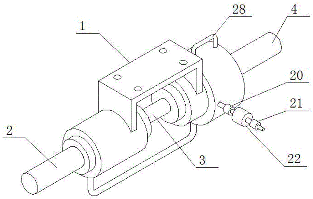
图1为本发明的结构示意图;Fig. 1 is the structural representation of the present invention;
图2为本发明的安装固定架的结构示意图;Fig. 2 is the structural representation of the installation fixing frame of the present invention;
图3为本发明的剖视的结构示意图;3 is a cross-sectional structural schematic diagram of the present invention;
图4为本发明的输出轴组、控制轴组和输入轴组配合的结构示意图;4 is a schematic structural diagram of the coordination of the output shaft group, the control shaft group and the input shaft group of the present invention;
图5为本发明的控制轴组的结构示意图;5 is a schematic structural diagram of a control shaft group of the present invention;
图6为本发明的输出轴组、控制轴组和输入轴组剖视的结构示意图;6 is a schematic structural diagram of the cross-sectional view of the output shaft group, the control shaft group and the input shaft group of the present invention;
图中:1-安装固定架、2-输出轴组、3-控制轴组、4-输入轴组、5-安装板、6-输出定位套、7-输入定位套、8-输出轴、9-输出滑套、10-输出滑动腔、11-油缸、12-空载腔、13-输出滑槽、14-输入轴、15-输入滑套、16-滑动腔、17-输入滑槽、18-油腔、19-螺旋叶片、20-蓄能单向阀、21-蓄能罐、22-压力阀、23-进油管、24-输出三棱圆柱、25-输入三棱圆柱、26-复位弹簧、27-环型槽、28-回油管、29-滑板、30-滚珠。In the figure: 1-installation bracket, 2-output shaft group, 3-control shaft group, 4-input shaft group, 5-installation plate, 6-output positioning sleeve, 7-input positioning sleeve, 8-output shaft, 9 -Output sliding sleeve, 10-Output sliding cavity, 11-Cylinder, 12-No-load cavity, 13-Output sliding groove, 14-Input shaft, 15-Input sliding sleeve, 16-Sliding cavity, 17-Input sliding groove, 18 -Oil cavity, 19-spiral blade, 20-energy storage check valve, 21-energy storage tank, 22-pressure valve, 23-oil inlet pipe, 24-output triangular cylinder, 25-input triangular cylinder, 26-reset Spring, 27-ring groove, 28-oil return pipe, 29-slide plate, 30-ball.
具体实施方式Detailed ways
下面将结合本发明实施例中的附图,对本发明实施例中的技术方案进行清楚、完整地描述,显然,所描述的实施例仅仅是本发明一部分实施例,而不是全部的实施例。基于本发明中的实施例,本领域普通技术人员在没有做出创造性劳动前提下所获得的所有其他实施例,都属于本发明保护的范围。The technical solutions in the embodiments of the present invention will be clearly and completely described below with reference to the accompanying drawings in the embodiments of the present invention. Obviously, the described embodiments are only a part of the embodiments of the present invention, but not all of the embodiments. Based on the embodiments of the present invention, all other embodiments obtained by those of ordinary skill in the art without creative efforts shall fall within the protection scope of the present invention.
请参阅图1-6,本发明提供一种技术方案:Please refer to Figures 1-6, the present invention provides a technical solution:
一种具有防止误操作的汽车驱动轴,包括安装固定架1、输出轴组2、控制轴组3和输入轴组4,所述安装固定架1上设置有安装板5,所述安装板5的底部两端侧壁上通过连接板连接有输出定位套6和输入定位套7,所述输出轴组2的一端贯穿套设在输出定位套6上,所述输入轴组4的一端贯穿套设在输入定位套7上,所述输出轴组2通过控制轴组3和输入轴组4连接,所述输出轴组2上设置有输出轴8和输出滑套9,所述输出滑套9内设设置有输出滑动腔10和油缸11,所述输出滑动腔10的一端设置有空载腔12,所述输出滑动腔10的内侧壁位于空载腔12的一侧均匀开设有输出滑槽13,所述油缸11设置在输出滑动腔10的另一端,所述输入轴组4上设置有输入轴14和输入滑套15,所述输入滑套15内设置有输入滑动腔16,所述输入滑动腔16的内侧壁上均匀开设有输入滑槽17,所述输入定位套7内设置有油腔18,所述输入滑套15的外边侧位于油腔18内焊接有螺旋叶片19,所述输入定位套7的一端外边侧设置有蓄能单向阀20和排油管,所述蓄能单向阀20的另一端连接有蓄能罐21,所述蓄能罐21的一端设置有压力阀22,所述输出定位套6的外边侧焊接有进油管23,所述进油管23通过管路和排油管连接,所述控制轴组3上设置有输出三棱圆柱24和输入三棱圆柱25。An automobile drive shaft with preventing misoperation, comprising an
作为本发明的一种优选实施方式,所述油缸11上设置有驱动杆,所述驱动杆的一端延伸至输出三棱圆柱24的侧壁上。As a preferred embodiment of the present invention, the
作为本发明的一种优选实施方式,所述输入三棱圆柱25的一侧设置有复位弹簧26。As a preferred embodiment of the present invention, a
作为本发明的一种优选实施方式,所述输出滑套9的外边侧均匀开设有油道,所述油道的一端通过管路和油缸11连接,所述输出定位套6的内侧壁开设有和油道相对应的环型槽27,所述进油管23和环型槽27连通。As a preferred embodiment of the present invention, oil passages are evenly opened on the outer side of the
作为本发明的一种优选实施方式,所述输入定位套7的外边侧设置和油腔18连通的回油管28。As a preferred embodiment of the present invention, an
作为本发明的一种优选实施方式,所述输出三棱圆柱24和输入三棱圆柱25上设置有滑板29,所述滑板29内设置有回转轴,所述回转轴上套设有滚珠30,所述滚珠30与输出滑槽13和输入滑槽17相对应。As a preferred embodiment of the present invention, the output
作为本发明的一种优选实施方式,所述输入定位套7和输入滑套15之间位于油腔18的两端设置有密封圈,所述油腔18内设置有液压油。As a preferred embodiment of the present invention, sealing rings are provided at both ends of the
工作原理:首先对此驱动轴进行安装,将输入轴14连接外部动力输出端,将输出轴8连通外部驱动轮,同时在油腔18内填充液压油,然后将安装板5通过螺栓安装在外部固定板上,正常行驶过程中输入轴14旋转通过控制轴组3带动输出轴组2分别在输入定位套17和输出定位套16内旋转进行传递动力,当突发意外事故时,驾驶员来不及进行刹车出现猛踏油门是,输入轴14瞬间高速旋转,输出滑套9外部的螺旋叶片19由正常的推动液压油通过回油管28的循环转变为液压油来不及循环并通过进油管23进入到和环型槽27内,并通过油道进入油缸11内,油缸11开始推程推动输出轴组2上的输出三棱圆柱24向右运动,由于滑板29上滚珠30作用下,可以减少滑动摩擦力,当滑板29脱离输出滑槽13进入空载腔12后,动力传输停止,这样可以防止误操作持续增大驱动力的功能;正常行驶过程中,油腔18内的液压油,在螺旋叶片19旋转的推力下一部分通过蓄能单向阀20进入到蓄能罐21内,瞬间的螺旋叶片19高速旋转,可以将一部分液压油送入到蓄能罐21内,蓄能罐21压力增大时,压力阀22打开并向刹车油路供油进行刹车,这样可以避免出现机车起步或倒车时,因错踏油门出现的意外发生。Working principle: First install the drive shaft, connect the
尽管已经示出和描述了本发明的实施例,对于本领域的普通技术人员而言,可以理解在不脱离本发明的原理和精神的情况下可以对这些实施例进行多种变化、修改、替换和变型,本发明的范围由所附权利要求及其等同物限定。Although embodiments of the present invention have been shown and described, it will be understood by those skilled in the art that various changes, modifications, and substitutions can be made in these embodiments without departing from the principle and spirit of the invention and modifications, the scope of the present invention is defined by the appended claims and their equivalents.
Claims (5)
Priority Applications (1)
| Application Number | Priority Date | Filing Date | Title |
|---|---|---|---|
| CN201911210725.2A CN110843749B (en) | 2019-12-02 | 2019-12-02 | An automobile drive shaft with preventing misoperation |
Applications Claiming Priority (1)
| Application Number | Priority Date | Filing Date | Title |
|---|---|---|---|
| CN201911210725.2A CN110843749B (en) | 2019-12-02 | 2019-12-02 | An automobile drive shaft with preventing misoperation |
Publications (2)
| Publication Number | Publication Date |
|---|---|
| CN110843749A CN110843749A (en) | 2020-02-28 |
| CN110843749B true CN110843749B (en) | 2020-12-29 |
Family
ID=69607357
Family Applications (1)
| Application Number | Title | Priority Date | Filing Date |
|---|---|---|---|
| CN201911210725.2A Expired - Fee Related CN110843749B (en) | 2019-12-02 | 2019-12-02 | An automobile drive shaft with preventing misoperation |
Country Status (1)
| Country | Link |
|---|---|
| CN (1) | CN110843749B (en) |
Families Citing this family (1)
| Publication number | Priority date | Publication date | Assignee | Title |
|---|---|---|---|---|
| CN108295795B (en) * | 2018-04-26 | 2023-06-09 | 南京林业大学 | A low-loss stirring reactor heated by heat conduction oil |
Citations (7)
| Publication number | Priority date | Publication date | Assignee | Title |
|---|---|---|---|---|
| JPH08253054A (en) * | 1995-03-15 | 1996-10-01 | Masae Watanabe | Accelerator erroneous operation preventing device of automobile |
| CN201415665Y (en) * | 2009-06-24 | 2010-03-03 | 重庆理工大学 | Automobile throttle brake device |
| CN202038296U (en) * | 2010-06-08 | 2011-11-16 | 武成尚 | Sudden throttle acceleration automobile-braking device |
| CN105966243A (en) * | 2016-07-04 | 2016-09-28 | 安徽工程大学 | Accelerator pedal device |
| CN106553546A (en) * | 2017-01-04 | 2017-04-05 | 黄文年 | A kind of mis-accelerator pressing of improvement becomes brake system |
| CN108501718A (en) * | 2018-06-21 | 2018-09-07 | 孙雷 | A kind of braking mechanism of the accelerator stepping misoperation preventing based on damper mechanism |
| CN110509903A (en) * | 2019-09-27 | 2019-11-29 | 安徽信息工程学院 | A device for converting a false step on the accelerator into an emergency brake and its application method |
-
2019
- 2019-12-02 CN CN201911210725.2A patent/CN110843749B/en not_active Expired - Fee Related
Patent Citations (7)
| Publication number | Priority date | Publication date | Assignee | Title |
|---|---|---|---|---|
| JPH08253054A (en) * | 1995-03-15 | 1996-10-01 | Masae Watanabe | Accelerator erroneous operation preventing device of automobile |
| CN201415665Y (en) * | 2009-06-24 | 2010-03-03 | 重庆理工大学 | Automobile throttle brake device |
| CN202038296U (en) * | 2010-06-08 | 2011-11-16 | 武成尚 | Sudden throttle acceleration automobile-braking device |
| CN105966243A (en) * | 2016-07-04 | 2016-09-28 | 安徽工程大学 | Accelerator pedal device |
| CN106553546A (en) * | 2017-01-04 | 2017-04-05 | 黄文年 | A kind of mis-accelerator pressing of improvement becomes brake system |
| CN108501718A (en) * | 2018-06-21 | 2018-09-07 | 孙雷 | A kind of braking mechanism of the accelerator stepping misoperation preventing based on damper mechanism |
| CN110509903A (en) * | 2019-09-27 | 2019-11-29 | 安徽信息工程学院 | A device for converting a false step on the accelerator into an emergency brake and its application method |
Also Published As
| Publication number | Publication date |
|---|---|
| CN110843749A (en) | 2020-02-28 |
Similar Documents
| Publication | Publication Date | Title |
|---|---|---|
| CN103223849B (en) | A kind of parallel-connection type hybrid power driver for vehicle | |
| CN105202074B (en) | A kind of parallel hydraulic retarder and its separation method with arrangement of clutch | |
| US20050173212A1 (en) | Hydrodynamic brake | |
| EP2471679A2 (en) | Apparatus and method for operating a hybrid drive system during an extended braking condition | |
| CN105667467B (en) | A kind of spring braking energy accumulation vehicle starting device | |
| CN110843749B (en) | An automobile drive shaft with preventing misoperation | |
| CN107972650A (en) | Hydraulic-pneumatic composite braking system for the protection of flame proof rubber tyre vehicle band door | |
| CN105715704B (en) | Fluid damping formula brakes | |
| CN202574170U (en) | Automobile braking device | |
| CN113879392A (en) | Intelligent auxiliary steering power-assisted system utilizing braking energy and control method | |
| CN103821851B (en) | Double forward blade hydrodynamic retarder | |
| CN203868191U (en) | Double-row forward inclined blade type hydraulic retarder | |
| CN206036170U (en) | Hydraulic transmission device with hydrodynamic brake | |
| CN109340320A (en) | A kind of wheel side speed reducer | |
| CN104842973A (en) | Hydraulic retarder for heavy truck axle | |
| CN110081096A (en) | A kind of fluid power deceleration device | |
| CN107351827A (en) | A kind of hydrostatically driven vehicle walking brakes | |
| CN106438913A (en) | Hydraulic drive device with hydraulic brake | |
| CN113513571B (en) | Hydraulic impact type power transmission device | |
| CN108357484B (en) | A vehicle with braking energy storage function | |
| CN109132772B (en) | Elevator overspeed protection device | |
| CN215444969U (en) | Hydraulic impact type power transmission device | |
| CN205890849U (en) | Auxiliary braking system all | |
| CN117662744A (en) | Hydraulic transmission case control system for oil filling braking of reverse part of torque converter | |
| CN212579830U (en) | A high-efficiency hydraulic braking device |
Legal Events
| Date | Code | Title | Description |
|---|---|---|---|
| PB01 | Publication | ||
| PB01 | Publication | ||
| SE01 | Entry into force of request for substantive examination | ||
| SE01 | Entry into force of request for substantive examination | ||
| CB03 | Change of inventor or designer information |
Inventor after: Li Feng Inventor after: Yu Pinchun Inventor after: Cao Kaiming Inventor after: Wang Juncai Inventor after: Wang Haiyu Inventor after: Pei Mingli Inventor before: Li Feng |
|
| CB03 | Change of inventor or designer information | ||
| TA01 | Transfer of patent application right |
Effective date of registration: 20201208 Address after: 325000 Luofeng Shuangqiao Industrial Zone, Tangxia Town, Wenzhou City, Zhejiang Province Applicant after: Wenzhou Juquan Auto Parts Co.,Ltd. Address before: 236800 No.22, Weiyuan Road, Qiaocheng District, Bozhou City, Anhui Province Applicant before: Li Feng |
|
| TA01 | Transfer of patent application right | ||
| GR01 | Patent grant | ||
| GR01 | Patent grant | ||
| PE01 | Entry into force of the registration of the contract for pledge of patent right |
Denomination of invention: A kind of automobile drive shaft with prevention of misoperation Effective date of registration: 20221014 Granted publication date: 20201229 Pledgee: Zhejiang Ruian rural commercial bank Limited by Share Ltd. Field Bridge Branch Pledgor: Wenzhou Juquan Auto Parts Co.,Ltd. Registration number: Y2022500000086 |
|
| PE01 | Entry into force of the registration of the contract for pledge of patent right | ||
| PC01 | Cancellation of the registration of the contract for pledge of patent right |
Date of cancellation: 20231008 Granted publication date: 20201229 Pledgee: Zhejiang Ruian rural commercial bank Limited by Share Ltd. Field Bridge Branch Pledgor: Wenzhou Juquan Auto Parts Co.,Ltd. Registration number: Y2022500000086 |
|
| PC01 | Cancellation of the registration of the contract for pledge of patent right | ||
| PE01 | Entry into force of the registration of the contract for pledge of patent right |
Denomination of invention: A car drive shaft with anti misoperation function Effective date of registration: 20231116 Granted publication date: 20201229 Pledgee: Zhejiang Ruian rural commercial bank Limited by Share Ltd. Field Bridge Branch Pledgor: Wenzhou Juquan Auto Parts Co.,Ltd. Registration number: Y2023980065942 |
|
| PE01 | Entry into force of the registration of the contract for pledge of patent right | ||
| CF01 | Termination of patent right due to non-payment of annual fee |
Granted publication date: 20201229 |
|
| CF01 | Termination of patent right due to non-payment of annual fee |