CN110833455A - Flexible instrument with embedded actuation catheter - Google Patents
Flexible instrument with embedded actuation catheter Download PDFInfo
- Publication number
- CN110833455A CN110833455A CN201911224573.1A CN201911224573A CN110833455A CN 110833455 A CN110833455 A CN 110833455A CN 201911224573 A CN201911224573 A CN 201911224573A CN 110833455 A CN110833455 A CN 110833455A
- Authority
- CN
- China
- Prior art keywords
- flexible body
- catheter
- tube
- flexible
- wall
- Prior art date
- Legal status (The legal status is an assumption and is not a legal conclusion. Google has not performed a legal analysis and makes no representation as to the accuracy of the status listed.)
- Granted
Links
- 210000002435 tendon Anatomy 0.000 claims abstract description 40
- 230000007704 transition Effects 0.000 claims description 23
- 238000000034 method Methods 0.000 description 28
- 210000003484 anatomy Anatomy 0.000 description 13
- 230000000670 limiting effect Effects 0.000 description 13
- 239000000463 material Substances 0.000 description 12
- 238000003384 imaging method Methods 0.000 description 9
- 239000000835 fiber Substances 0.000 description 7
- 230000033001 locomotion Effects 0.000 description 7
- 238000001574 biopsy Methods 0.000 description 5
- 239000002131 composite material Substances 0.000 description 5
- 239000013307 optical fiber Substances 0.000 description 5
- 238000004891 communication Methods 0.000 description 4
- 238000005520 cutting process Methods 0.000 description 4
- 239000012636 effector Substances 0.000 description 4
- HLXZNVUGXRDIFK-UHFFFAOYSA-N nickel titanium Chemical compound [Ti].[Ti].[Ti].[Ti].[Ti].[Ti].[Ti].[Ti].[Ti].[Ti].[Ti].[Ni].[Ni].[Ni].[Ni].[Ni].[Ni].[Ni].[Ni].[Ni].[Ni].[Ni].[Ni].[Ni].[Ni] HLXZNVUGXRDIFK-UHFFFAOYSA-N 0.000 description 4
- 229910001000 nickel titanium Inorganic materials 0.000 description 4
- 238000012014 optical coherence tomography Methods 0.000 description 4
- 230000008569 process Effects 0.000 description 4
- 230000004044 response Effects 0.000 description 4
- 238000003860 storage Methods 0.000 description 4
- 238000001356 surgical procedure Methods 0.000 description 4
- 238000001931 thermography Methods 0.000 description 4
- 238000011282 treatment Methods 0.000 description 4
- 238000004873 anchoring Methods 0.000 description 3
- -1 but not limited to Substances 0.000 description 3
- 238000010276 construction Methods 0.000 description 3
- 230000007423 decrease Effects 0.000 description 3
- 210000004072 lung Anatomy 0.000 description 3
- 230000036961 partial effect Effects 0.000 description 3
- 238000012545 processing Methods 0.000 description 3
- 239000000523 sample Substances 0.000 description 3
- 239000004065 semiconductor Substances 0.000 description 3
- 239000010935 stainless steel Substances 0.000 description 3
- 229910001220 stainless steel Inorganic materials 0.000 description 3
- 229920002614 Polyether block amide Polymers 0.000 description 2
- 239000004642 Polyimide Substances 0.000 description 2
- 206010052428 Wound Diseases 0.000 description 2
- 208000027418 Wounds and injury Diseases 0.000 description 2
- 230000000712 assembly Effects 0.000 description 2
- 238000000429 assembly Methods 0.000 description 2
- 210000001072 colon Anatomy 0.000 description 2
- 230000006835 compression Effects 0.000 description 2
- 238000007906 compression Methods 0.000 description 2
- 238000003745 diagnosis Methods 0.000 description 2
- 230000005672 electromagnetic field Effects 0.000 description 2
- 238000005530 etching Methods 0.000 description 2
- 238000002594 fluoroscopy Methods 0.000 description 2
- 210000002216 heart Anatomy 0.000 description 2
- 210000000936 intestine Anatomy 0.000 description 2
- 210000003734 kidney Anatomy 0.000 description 2
- 238000003698 laser cutting Methods 0.000 description 2
- 238000002595 magnetic resonance imaging Methods 0.000 description 2
- 238000004519 manufacturing process Methods 0.000 description 2
- 238000005259 measurement Methods 0.000 description 2
- 230000004048 modification Effects 0.000 description 2
- 238000012986 modification Methods 0.000 description 2
- 239000002071 nanotube Substances 0.000 description 2
- 230000003287 optical effect Effects 0.000 description 2
- 229920001721 polyimide Polymers 0.000 description 2
- 238000001454 recorded image Methods 0.000 description 2
- 230000001225 therapeutic effect Effects 0.000 description 2
- 238000003325 tomography Methods 0.000 description 2
- 238000002604 ultrasonography Methods 0.000 description 2
- 239000011165 3D composite Substances 0.000 description 1
- 239000004677 Nylon Substances 0.000 description 1
- 238000001069 Raman spectroscopy Methods 0.000 description 1
- 208000002847 Surgical Wound Diseases 0.000 description 1
- RTAQQCXQSZGOHL-UHFFFAOYSA-N Titanium Chemical compound [Ti] RTAQQCXQSZGOHL-UHFFFAOYSA-N 0.000 description 1
- 239000004699 Ultra-high molecular weight polyethylene Substances 0.000 description 1
- 230000001133 acceleration Effects 0.000 description 1
- 239000000853 adhesive Substances 0.000 description 1
- 230000001070 adhesive effect Effects 0.000 description 1
- 238000005452 bending Methods 0.000 description 1
- 239000000560 biocompatible material Substances 0.000 description 1
- 230000005540 biological transmission Effects 0.000 description 1
- 210000004556 brain Anatomy 0.000 description 1
- 230000008859 change Effects 0.000 description 1
- 230000003247 decreasing effect Effects 0.000 description 1
- 238000002405 diagnostic procedure Methods 0.000 description 1
- 238000010586 diagram Methods 0.000 description 1
- 229910003460 diamond Inorganic materials 0.000 description 1
- 239000010432 diamond Substances 0.000 description 1
- 239000003814 drug Substances 0.000 description 1
- 229940079593 drug Drugs 0.000 description 1
- 230000000694 effects Effects 0.000 description 1
- 238000009760 electrical discharge machining Methods 0.000 description 1
- 238000001839 endoscopy Methods 0.000 description 1
- 238000005516 engineering process Methods 0.000 description 1
- 230000006870 function Effects 0.000 description 1
- 238000002675 image-guided surgery Methods 0.000 description 1
- 238000007373 indentation Methods 0.000 description 1
- 238000002329 infrared spectrum Methods 0.000 description 1
- 238000003780 insertion Methods 0.000 description 1
- 230000037431 insertion Effects 0.000 description 1
- 230000003434 inspiratory effect Effects 0.000 description 1
- 238000013152 interventional procedure Methods 0.000 description 1
- 230000001788 irregular Effects 0.000 description 1
- 230000002262 irrigation Effects 0.000 description 1
- 238000003973 irrigation Methods 0.000 description 1
- 238000000608 laser ablation Methods 0.000 description 1
- 230000007246 mechanism Effects 0.000 description 1
- 238000002844 melting Methods 0.000 description 1
- 230000008018 melting Effects 0.000 description 1
- 238000002324 minimally invasive surgery Methods 0.000 description 1
- 239000000203 mixture Substances 0.000 description 1
- 238000012544 monitoring process Methods 0.000 description 1
- 229920001778 nylon Polymers 0.000 description 1
- 210000000056 organ Anatomy 0.000 description 1
- 230000008447 perception Effects 0.000 description 1
- 230000000737 periodic effect Effects 0.000 description 1
- 239000004033 plastic Substances 0.000 description 1
- 229920003023 plastic Polymers 0.000 description 1
- 239000004810 polytetrafluoroethylene Substances 0.000 description 1
- 229920001343 polytetrafluoroethylene Polymers 0.000 description 1
- 229920002635 polyurethane Polymers 0.000 description 1
- 239000004814 polyurethane Substances 0.000 description 1
- 238000011084 recovery Methods 0.000 description 1
- 230000002829 reductive effect Effects 0.000 description 1
- 230000000452 restraining effect Effects 0.000 description 1
- 238000000926 separation method Methods 0.000 description 1
- 239000012781 shape memory material Substances 0.000 description 1
- 230000003068 static effect Effects 0.000 description 1
- 238000004381 surface treatment Methods 0.000 description 1
- 238000002560 therapeutic procedure Methods 0.000 description 1
- 229910052719 titanium Inorganic materials 0.000 description 1
- 239000010936 titanium Substances 0.000 description 1
- 229920000785 ultra high molecular weight polyethylene Polymers 0.000 description 1
- 238000002211 ultraviolet spectrum Methods 0.000 description 1
- 238000001429 visible spectrum Methods 0.000 description 1
- 238000012800 visualization Methods 0.000 description 1
- XLYOFNOQVPJJNP-UHFFFAOYSA-N water Substances O XLYOFNOQVPJJNP-UHFFFAOYSA-N 0.000 description 1
Images


Classifications
-
- A—HUMAN NECESSITIES
- A61—MEDICAL OR VETERINARY SCIENCE; HYGIENE
- A61B—DIAGNOSIS; SURGERY; IDENTIFICATION
- A61B34/00—Computer-aided surgery; Manipulators or robots specially adapted for use in surgery
- A61B34/70—Manipulators specially adapted for use in surgery
- A61B34/71—Manipulators operated by drive cable mechanisms
-
- A—HUMAN NECESSITIES
- A61—MEDICAL OR VETERINARY SCIENCE; HYGIENE
- A61B—DIAGNOSIS; SURGERY; IDENTIFICATION
- A61B34/00—Computer-aided surgery; Manipulators or robots specially adapted for use in surgery
- A61B34/30—Surgical robots
- A61B34/35—Surgical robots for telesurgery
-
- A—HUMAN NECESSITIES
- A61—MEDICAL OR VETERINARY SCIENCE; HYGIENE
- A61B—DIAGNOSIS; SURGERY; IDENTIFICATION
- A61B17/00—Surgical instruments, devices or methods
- A61B17/00234—Surgical instruments, devices or methods for minimally invasive surgery
-
- A—HUMAN NECESSITIES
- A61—MEDICAL OR VETERINARY SCIENCE; HYGIENE
- A61B—DIAGNOSIS; SURGERY; IDENTIFICATION
- A61B34/00—Computer-aided surgery; Manipulators or robots specially adapted for use in surgery
- A61B34/20—Surgical navigation systems; Devices for tracking or guiding surgical instruments, e.g. for frameless stereotaxis
-
- A—HUMAN NECESSITIES
- A61—MEDICAL OR VETERINARY SCIENCE; HYGIENE
- A61B—DIAGNOSIS; SURGERY; IDENTIFICATION
- A61B34/00—Computer-aided surgery; Manipulators or robots specially adapted for use in surgery
- A61B34/30—Surgical robots
-
- A—HUMAN NECESSITIES
- A61—MEDICAL OR VETERINARY SCIENCE; HYGIENE
- A61B—DIAGNOSIS; SURGERY; IDENTIFICATION
- A61B17/00—Surgical instruments, devices or methods
- A61B17/00234—Surgical instruments, devices or methods for minimally invasive surgery
- A61B2017/00292—Surgical instruments, devices or methods for minimally invasive surgery mounted on or guided by flexible, e.g. catheter-like, means
- A61B2017/003—Steerable
- A61B2017/00305—Constructional details of the flexible means
- A61B2017/00309—Cut-outs or slits
-
- A—HUMAN NECESSITIES
- A61—MEDICAL OR VETERINARY SCIENCE; HYGIENE
- A61B—DIAGNOSIS; SURGERY; IDENTIFICATION
- A61B17/00—Surgical instruments, devices or methods
- A61B17/00234—Surgical instruments, devices or methods for minimally invasive surgery
- A61B2017/00292—Surgical instruments, devices or methods for minimally invasive surgery mounted on or guided by flexible, e.g. catheter-like, means
- A61B2017/003—Steerable
- A61B2017/00318—Steering mechanisms
- A61B2017/00323—Cables or rods
-
- A—HUMAN NECESSITIES
- A61—MEDICAL OR VETERINARY SCIENCE; HYGIENE
- A61B—DIAGNOSIS; SURGERY; IDENTIFICATION
- A61B34/00—Computer-aided surgery; Manipulators or robots specially adapted for use in surgery
- A61B34/20—Surgical navigation systems; Devices for tracking or guiding surgical instruments, e.g. for frameless stereotaxis
- A61B2034/2046—Tracking techniques
- A61B2034/2061—Tracking techniques using shape-sensors, e.g. fiber shape sensors with Bragg gratings
-
- A—HUMAN NECESSITIES
- A61—MEDICAL OR VETERINARY SCIENCE; HYGIENE
- A61B—DIAGNOSIS; SURGERY; IDENTIFICATION
- A61B34/00—Computer-aided surgery; Manipulators or robots specially adapted for use in surgery
- A61B34/20—Surgical navigation systems; Devices for tracking or guiding surgical instruments, e.g. for frameless stereotaxis
- A61B2034/2046—Tracking techniques
- A61B2034/2065—Tracking using image or pattern recognition
-
- A—HUMAN NECESSITIES
- A61—MEDICAL OR VETERINARY SCIENCE; HYGIENE
- A61B—DIAGNOSIS; SURGERY; IDENTIFICATION
- A61B34/00—Computer-aided surgery; Manipulators or robots specially adapted for use in surgery
- A61B34/30—Surgical robots
- A61B2034/301—Surgical robots for introducing or steering flexible instruments inserted into the body, e.g. catheters or endoscopes
-
- A—HUMAN NECESSITIES
- A61—MEDICAL OR VETERINARY SCIENCE; HYGIENE
- A61M—DEVICES FOR INTRODUCING MEDIA INTO, OR ONTO, THE BODY; DEVICES FOR TRANSDUCING BODY MEDIA OR FOR TAKING MEDIA FROM THE BODY; DEVICES FOR PRODUCING OR ENDING SLEEP OR STUPOR
- A61M25/00—Catheters; Hollow probes
- A61M25/01—Introducing, guiding, advancing, emplacing or holding catheters
- A61M25/0105—Steering means as part of the catheter or advancing means; Markers for positioning
- A61M25/0133—Tip steering devices
- A61M25/0147—Tip steering devices with movable mechanical means, e.g. pull wires
Landscapes
- Health & Medical Sciences (AREA)
- Life Sciences & Earth Sciences (AREA)
- Engineering & Computer Science (AREA)
- Surgery (AREA)
- Animal Behavior & Ethology (AREA)
- General Health & Medical Sciences (AREA)
- Biomedical Technology (AREA)
- Heart & Thoracic Surgery (AREA)
- Veterinary Medicine (AREA)
- Public Health (AREA)
- Molecular Biology (AREA)
- Nuclear Medicine, Radiotherapy & Molecular Imaging (AREA)
- Medical Informatics (AREA)
- Robotics (AREA)
- Mechanical Engineering (AREA)
- Biophysics (AREA)
- Pulmonology (AREA)
- Anesthesiology (AREA)
- Hematology (AREA)
- Endoscopes (AREA)
- Manipulator (AREA)
Abstract
本发明的发明名称为带有嵌入式致动导管的柔性器械。本申请描述的是一种微创手术器械,其包括细长柔性体、多个导管和至少一个肌腱,所述细长柔性体包括近端部分和远端部分,所述至少一个肌腱从细长柔性体的近端部分延伸穿过多个导管中的至少一个的导管内腔进入到细长柔性体的远端部分中。细长柔性体包括中心内腔和具有从内表面延伸到外表面的厚度的柔性壁。每个导管包括导管内腔并延伸穿过细长柔性体的壁且在细长柔性体的柔性壁内终止。每个导管包括直接固定到柔性壁的远端。所述至少一个肌腱可致动以使远端部分转向。

The title of the invention of the present invention is a flexible instrument with an embedded actuating catheter. Described herein is a minimally invasive surgical instrument comprising an elongated flexible body including a proximal portion and a distal portion, a plurality of conduits, and at least one tendon, the at least one tendon extending from the elongated A proximal portion of the flexible body extends through a catheter lumen of at least one of the plurality of catheters into a distal portion of the elongated flexible body. The elongate flexible body includes a central lumen and a flexible wall having a thickness extending from the inner surface to the outer surface. Each catheter includes a catheter lumen and extends through and terminates within the flexible wall of the elongate flexible body. Each catheter includes a distal end secured directly to the flexible wall. The at least one tendon is actuatable to steer the distal portion.
Description
本申请是分案申请,原申请的申请日为2014年10月24日、申请号为201480057531.2、发明名称为“带有嵌入式致动导管的柔性器械”。This application is a divisional application. The application date of the original application is October 24, 2014, the application number is 201480057531.2, and the invention name is "flexible device with embedded actuating catheter".
技术领域technical field
本公开涉及用于导航患者解剖结构以引导微创步骤的系统和方法,且更具体地,涉及用于使低型面(low-profile)柔性介入器械转向到患者解剖结构中的装置和方法。The present disclosure relates to systems and methods for navigating patient anatomy to guide minimally invasive procedures, and more particularly, to devices and methods for steering low-profile flexible interventional instruments into patient anatomy.
背景技术Background technique
微创医疗技术旨在减少在介入步骤过程中受损的组织量,因而减少患者康复时间、不适及有害的副作用。这类微创技术可通过患者解剖结构中的自然孔口或通过一个或多个手术切口执行。通过这些自然孔口或切口,临床医生可插入介入器械(包括手术的、诊断的、治疗的,或活组织检查器械)以到达目标组织位置。为了到达目标组织位置,微创介入器械可导航解剖系统中的自然通道或外科手术创建的通道,所述解剖系统中的自然通道诸如肺、结肠、肠、肾、心脏、循环系统,等等。一些微创医疗器械可为远程操作的或计算机辅助的。遥控机器人介入器械可用于导航穿过患者解剖结构,且此类器械需要足够小以物理地安装在那些解剖内腔内。制造柔性遥控机器人器械可具有挑战性,该柔性遥控机器人被设计大小以包括适于远程操作或遥控机器人操作的机械结构并具有足够小的外直径以导航此类小通道。需要改进的设备和系统以用于经配置以插入解剖通道或手术创建的通道中的遥控机器人手术器械。Minimally invasive medical techniques are designed to reduce the amount of tissue damaged during interventional procedures, thereby reducing patient recovery time, discomfort and harmful side effects. Such minimally invasive techniques can be performed through natural orifices in the patient's anatomy or through one or more surgical incisions. Through these natural orifices or incisions, clinicians may insert interventional instruments (including surgical, diagnostic, therapeutic, or biopsy instruments) to reach target tissue locations. To reach a target tissue location, minimally invasive interventional instruments can navigate natural or surgically created passages in anatomical systems such as lung, colon, intestine, kidney, heart, circulatory system, and the like. Some minimally invasive medical devices may be teleoperated or computer-assisted. Telerobotic interventional instruments can be used to navigate through patient anatomy, and such instruments need to be small enough to physically fit within those anatomical lumens. It can be challenging to manufacture a flexible telerobotic instrument that is sized to include mechanical structures suitable for teleoperation or telerobotic manipulation and has an outer diameter small enough to navigate such small passageways. There is a need for improved apparatus and systems for telerobotic surgical instruments configured for insertion into anatomical or surgically created channels.
发明内容SUMMARY OF THE INVENTION
本发明的实施例通过随附于本说明书的权利要求概述。Embodiments of the invention are summarized by the claims appended to this specification.
在一个实施例中,本公开涉及包括细长柔性体、多个导管,和至少一个肌腱的微创手术器械或诊断器械。一方面,细长柔性体包括近端部分、远端部分、中心内腔和具有从细长柔性体的内表面延伸到细长柔性体的外表面的厚度的柔性壁。一方面,多个导管延伸穿过近端部分中的细长柔性体的柔性壁并在细长柔性体的柔性壁内终止。一方面,每个导管包括导管内腔和远端。一方面,远端直接固定到柔性壁。一方面,至少一个肌腱从细长柔性体的近端部分延伸穿过多个导管中的至少一个的导管内腔进入到细长柔性体的远端部分,且所述至少一个肌腱可致动以使远端部分转向。In one embodiment, the present disclosure relates to a minimally invasive surgical or diagnostic instrument comprising an elongated flexible body, a plurality of catheters, and at least one tendon. In one aspect, the elongated flexible body includes a proximal end portion, a distal end portion, a central lumen, and a flexible wall having a thickness extending from an inner surface of the elongated flexible body to an outer surface of the elongated flexible body. In one aspect, the plurality of conduits extend through and terminate within the flexible wall of the elongated flexible body in the proximal portion. In one aspect, each catheter includes a catheter lumen and a distal end. In one aspect, the distal end is fixed directly to the flexible wall. In one aspect, at least one tendon extends from a proximal portion of the elongate flexible body through a catheter lumen of at least one of the plurality of catheters into a distal portion of the elongate flexible body, and the at least one tendon is actuatable to Steer the distal portion.
一方面,微创手术器械或诊断器械进一步包括耦接到细长柔性体的远端部分的可转向管。一方面,可转向管包括内管表面、外管表面、具有在内管表面和外管表面之间延伸的管壁厚度的管壁,以及壁中的经配置以接收导管的多个渠道。In one aspect, the minimally invasive surgical or diagnostic instrument further includes a steerable tube coupled to the distal portion of the elongate flexible body. In one aspect, the steerable tube includes an inner tube surface, an outer tube surface, a tube wall having a tube wall thickness extending between the inner tube surface and the outer tube surface, and a plurality of channels in the wall configured to receive a conduit.
在另一实施例中,本公开涉及微创手术系统或诊断系统,其包括致动器、细长柔性体、多个导管,以及多个致动肌腱。一方面,细长柔性体包括近端部分、远端部分和从近端部分连续延伸到远端部分的柔性内护套。一方面,柔性内护套具有内表面和外表面。一方面,多个导管在内表面和外表面之间嵌入柔性内护套内。一方面,每个导管包括内腔和远端。一方面,每个导管延伸穿过柔性内护套并在所述柔性内护套内终止,其中每个远端直接附贴到柔性内护套。一方面,每个致动肌腱固定在相对于致动器的近端处且延伸穿过多个导管中的一个的内腔进入到远端部分中。一方面,多个致动肌腱通过致动器可致动以弯曲远端部分。In another embodiment, the present disclosure relates to a minimally invasive surgical or diagnostic system that includes an actuator, an elongated flexible body, a plurality of catheters, and a plurality of actuating tendons. In one aspect, the elongate flexible body includes a proximal portion, a distal portion, and a flexible inner sheath extending continuously from the proximal portion to the distal portion. In one aspect, the flexible inner sheath has an inner surface and an outer surface. In one aspect, the plurality of conduits are embedded within the flexible inner sheath between the inner and outer surfaces. In one aspect, each catheter includes a lumen and a distal end. In one aspect, each catheter extends through and terminates within the flexible inner sheath, wherein each distal end is directly attached to the flexible inner sheath. In one aspect, each actuating tendon is secured at a proximal end relative to the actuator and extends through the lumen of one of the plurality of catheters into the distal portion. In one aspect, a plurality of actuating tendons are actuatable by the actuator to flex the distal portion.
一方面,微创手术系统进一步包括耦接到细长柔性体的远端部分的可转向管。一方面,可转向管包括内管表面、外管表面、具有在内管表面和外管表面之间延伸的管壁厚度的管壁,以及壁中的经配置以接收导管的多个渠道。In one aspect, the minimally invasive surgical system further includes a steerable tube coupled to the distal portion of the elongate flexible body. In one aspect, the steerable tube includes an inner tube surface, an outer tube surface, a tube wall having a tube wall thickness extending between the inner tube surface and the outer tube surface, and a plurality of channels in the wall configured to receive a conduit.
应该理解,上述一般性描述和下面的详细描述二者本质上都是示例性和说明性的,且在不限制本公开的范围的情况下旨在提供本公开的理解。在这方面,根据下面的详细描述,本公开的附加方面、特征和优点对本领域技术人员来说将是显然的。It is to be understood that both the foregoing general description and the following detailed description are exemplary and explanatory in nature and are intended to provide an understanding of the disclosure without limiting the scope of the disclosure. In this regard, additional aspects, features and advantages of the present disclosure will be apparent to those skilled in the art from the following detailed description.
附图说明Description of drawings
当结合附图阅读时,根据以下的详细描述将更好地理解本公开的方面。应当强调的是,根据本行业中的标准惯例,各种特征不按比例绘制。事实上,为了讨论的清晰起见,各种特征的尺寸可任意增加或减少。此外,本公开在各种实例中可重复标识数字和/或字母。这种重复是为了简单清晰的目的且其自身不决定所讨论的各种实施例和/或配置之间的关系。Aspects of the present disclosure will be better understood from the following detailed description when read in conjunction with the accompanying drawings. It should be emphasized that, in accordance with standard practice in the industry, the various features are not drawn to scale. In fact, the dimensions of the various features may be arbitrarily increased or decreased for clarity of discussion. Furthermore, the present disclosure may repeatedly identify numbers and/or letters in various instances. This repetition is for the purpose of simplicity and clarity and does not in itself determine the relationship between the various embodiments and/or configurations discussed.
图1根据本公开的实施例示出遥控机器人介入系统。1 illustrates a telerobotic interventional system according to an embodiment of the present disclosure.
图2根据本公开的实施例示出介入器械系统。2 illustrates an interventional instrument system according to an embodiment of the present disclosure.
图3根据本公开的实施例示出导管系统的可转向部分,其示出启用系统的铰接的各种元件的相对位置。3 illustrates a steerable portion of a catheter system showing the relative positions of various elements that enable articulation of the system, according to an embodiment of the present disclosure.
图4根据本公开的实施例示出图2所示的器械系统的示例性近端部分的横截面图。4 illustrates a cross-sectional view of an exemplary proximal portion of the instrument system shown in FIG. 2 in accordance with an embodiment of the present disclosure.
图5根据本公开的实施例示出图2所示的器械系统的示例性远端部分的横截面图。5 illustrates a cross-sectional view of an exemplary distal portion of the instrument system shown in FIG. 2 in accordance with an embodiment of the present disclosure.
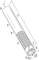
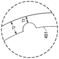
图6a根据本公开的一个实施例示出示例性可转向管的透视图。Figure 6a shows a perspective view of an exemplary steerable tube according to one embodiment of the present disclosure.
图6b示出图6a所示的示例性可转向管的一部分的详细透视图。Figure 6b shows a detailed perspective view of a portion of the exemplary steerable tube shown in Figure 6a.
图7示出图2所示的器械系统的示例性远端部分的横截面图。FIG. 7 shows a cross-sectional view of an exemplary distal portion of the instrument system shown in FIG. 2 .
图8根据本公开的一个实施例示出示例性可转向管的透视图。8 illustrates a perspective view of an exemplary steerable tube according to one embodiment of the present disclosure.
图9示出图2所示的器械系统的示例性远端部分的横截面图。FIG. 9 shows a cross-sectional view of an exemplary distal portion of the instrument system shown in FIG. 2 .
图10示出导航管状结构内的转弯的非示例性器械系统的示例性射线图像。10 shows an exemplary radiographic image of a non-exemplary instrument system for navigating turns within a tubular structure.
图11根据本公开的原理示出导航管状结构内的转弯的示例性器械系统的示例性射线图像,其中所述示例性器械系统包括嵌入式导管和可转向管。11 illustrates an exemplary radiograph of an exemplary instrument system for navigating turns within a tubular structure, wherein the exemplary instrument system includes an embedded catheter and a steerable tube, in accordance with the principles of the present disclosure.
具体实施方式Detailed ways
为了促进对本公开的原理的理解,现在参考附图中所示的实施例,且使用具体语言描述附图中所示的实施例。然而,应该理解,不旨在限制本公开的范围。在本发明方面的以下详细描述中,许多具体细节被陈述以便提供对公开的实施例的彻底理解。然而,对本领域技术人员显而易见的是,本公开的实施例可以在没有这些具体细节的情况下实施。没有详细描述其它情况中所熟知的方法、程序、组件,和电路以免不必要地混淆本发明的实施例的方面。To facilitate an understanding of the principles of the present disclosure, reference will now be made to the embodiments illustrated in the drawings, and specific language will be used to describe the embodiments illustrated in the drawings. It should be understood, however, that no limitation of the scope of the present disclosure is intended. In the following detailed description of aspects of the invention, numerous specific details are set forth in order to provide a thorough understanding of the disclosed embodiments. However, it will be apparent to those skilled in the art that the embodiments of the present disclosure may be practiced without these specific details. Other well-known methods, procedures, components, and circuits have not been described in detail so as not to unnecessarily obscure aspects of the embodiments of the invention.
所述设备、器械、方法,以及本公开的原理的任何进一步的应用的任何变化和进一步的修改完全可以预期是本公开相关领域的技术人员所通常能够想到的。具体地,完全可以预期,参考一个实施例所述的特征、组件和/或步骤可与参考本公开的其它实施例所述的特征、组件和/或步骤结合。此外,这里所提供的尺寸是用于具体实例且可以预期,不同的大小、尺寸,和/或比率可用于实施本公开的概念。为了避免不必要的描述性重复,根据一个说明性实施例描述的一个或多个组件或行为可被使用或省略,如其它说明性实施例可应用的那样。为简洁起见,这些组合的许多重复将不单独描述。为简单起见,在一些情况下,相同的标识号在视图中用于指相同或相似的部分。Any variations and further modifications of the described devices, apparatus, methods, and any further applications of the principles of the present disclosure are fully contemplated as would normally occur to those skilled in the art to which the present disclosure pertains. In particular, it is fully contemplated that features, components and/or steps described with reference to one embodiment may be combined with features, components and/or steps described with reference to other embodiments of the present disclosure. Furthermore, the dimensions provided herein are for specific examples and it is contemplated that different sizes, dimensions, and/or ratios may be used to implement the concepts of the present disclosure. To avoid unnecessary repetition of description, one or more components or acts described in accordance with one illustrative embodiment may be used or omitted as applicable to other illustrative embodiments. For the sake of brevity, many repetitions of these combinations will not be described separately. For simplicity, in some instances, the same identification numbers are used throughout the views to refer to the same or like parts.
实施例将在下面依照各种器械和器械的部分在三维空间中的状态描述各种器械和器械的部分。如本文所用的术语“位置”指三维空间中的物体或一部分物体的位置(例如,沿笛卡尔X、Y、Z坐标的3个平移自由度)。如本文所用的术语“取向”指物体或一部分物体的旋转安置(3个旋转自由度——例如,滚动、倾斜,和偏航(yaw))。如本文所用的术语“位姿(pose)”指至少1个平移自由度中的物体或一部分物体的位置且指至少一个旋转自由度(多至6个总自由度)中的那个物体或部分物体的取向。如本文所用的术语“形状”指沿细长物体测量的一组位姿、位置,或取向。Embodiments Various instruments and parts of instruments will be described below in terms of their states in three-dimensional space. The term "position" as used herein refers to the position of an object or a portion of an object in three-dimensional space (eg, 3 translational degrees of freedom along Cartesian X, Y, Z coordinates). The term "orientation" as used herein refers to the rotational orientation (3 rotational degrees of freedom - eg, roll, pitch, and yaw) of an object or a portion of an object. The term "pose" as used herein refers to the position of an object or part of an object in at least 1 translational degree of freedom and to that object or part of an object in at least one rotational degree of freedom (up to 6 total degrees of freedom) orientation. The term "shape" as used herein refers to a set of poses, positions, or orientations measured along an elongated object.
应该明白,术语“近端的”和“远端的”在本文中是以临床医生操纵从临床医生延伸到手术部位或诊断部位的器械的末端为参照的。术语“近端的”指更接近临床医生的器械部分,且术语“远端的”指进一步远离临床医生且更接近手术或诊断部位的器械部分。为清晰和简洁起见,空间术语,诸如“水平的”、“垂直的”、“在…上”,和“在…下”在本文中可参考附图使用。然而,手术或诊断器械用于许多取向和位置中,且这些术语并非是限制性的和绝对的。It should be understood that the terms "proximal" and "distal" are used herein with reference to the distal end of the instrument that the clinician manipulates extending from the clinician to the surgical or diagnostic site. The term "proximal" refers to the portion of the instrument that is closer to the clinician, and the term "distal" refers to the portion of the instrument that is further away from the clinician and closer to the site of surgery or diagnosis. For clarity and brevity, spatial terms such as "horizontal", "vertical", "on", and "under" may be used herein with reference to the drawings. However, surgical or diagnostic instruments are used in many orientations and positions, and these terms are not intended to be limiting and absolute.
本公开一般涉及用于致动线的导管或在铰接设备的操作中使用的肌腱。在一些情况下,本公开的实施例被配置为遥控机器人系统的部分。本领域技术人员将意识到本文所公开的嵌入式导管可在要求可转向器械的类似(例如,非遥控机器人)应用中使用。The present disclosure generally relates to catheters for actuation wires or tendons used in the operation of articulating devices. In some cases, embodiments of the present disclosure are configured as part of a telerobotic system. Those skilled in the art will appreciate that the embedded catheters disclosed herein may be used in similar (eg, non-tele-robot) applications requiring steerable instruments.
本文所公开的导管被成形并被配置为沿柔性器械(例如,导管)的长度运载控制肌腱或线。本文所公开的导管包括柔性导管,其穿过柔性器械的近端部分嵌入柔性器械的壁内。不是在离散的刚性结构处(例如,柔性器械的近端部分和远端部分之间的过渡处)终止,导管在近端部分的柔性壁内朝器械的远端可转向部分连续延伸并在器械的柔性壁内终止。具体地,导管在柔性壁内终止而不被锚定到柔性器械内的任何离散终端结构。控制肌腱在它们的终端处离开导管并继续穿过壁以延伸到器械的可转向远端部分中。通过消除用于导管的离散终端结构的需要且因此准许控制肌腱以不间断的方式从近端传到器械的远端部分,本文所公开的嵌入式导管允许柔性器械在其穿过弓形解剖通道时的连续弯曲(例如,非扭结弯曲或不间断弯曲)。因此,本文所公开的嵌入式导管可改善柔性器械(例如,铰接或可转向设备)的耐用性和性能,且可利用这类嵌入式导管增加用于柔性器械的合适应用的范围。The catheters disclosed herein are shaped and configured to carry control tendons or wires along the length of a flexible instrument (eg, catheter). The catheters disclosed herein include flexible catheters that are embedded within the wall of the flexible instrument through the proximal end portion of the flexible instrument. Rather than terminating at a discrete rigid structure (eg, at the transition between the proximal and distal portions of the flexible instrument), the conduit extends continuously within the flexible wall of the proximal portion toward the distal steerable portion of the instrument and extends beyond the instrument's distal steerable portion. terminated within the flexible wall. Specifically, the catheter terminates within the flexible wall without being anchored to any discrete termination structure within the flexible instrument. The control tendons exit the catheter at their terminal end and continue through the wall to extend into the steerable distal portion of the instrument. By eliminating the need for discrete terminal structures for the catheter and thus permitting control of the tendon to pass from the proximal end to the distal portion of the instrument in an uninterrupted manner, the embedded catheters disclosed herein allow flexible instruments as they pass through arcuate anatomical channels continuous bends (eg, non-kinked bends or uninterrupted bends). Accordingly, the embedded catheters disclosed herein can improve the durability and performance of flexible instruments (eg, articulating or steerable devices), and such embedded catheters can be utilized to increase the range of suitable applications for flexible instruments.
根据各种实施例,医疗程序(诸如活组织检查程序)可使用远程操作系统执行以引导器械输送。参考附图1,在例如包括诊断程序、治疗程序或外科手术程序的医疗程序中使用的远程操作医疗系统一般通过标识号100指示。如将描述的那样,本公开的远程操作医疗系统在外科医生的远程操作控制下。在可替换实施例中,远程操作医疗系统可在经编程以执行程序或子程序的计算机的部分控制下。仍在其它可替换实施例中,在经编程以执行程序或子程序的计算机的完全控制下,完全自动的医疗系统可用于执行程序或子程序。如图1所示,远程操作医疗系统100一般包括安装到患者P被安置其上的手术台O或在所述手术台O附近安装的远程操作总成102。医疗器械系统104被可操作地耦接至远程操作总成102。操作员输入系统106允许外科医生或其它类型的临床医生S观察手术部位的图像或表示手术部位的图像并控制医疗器械系统104的操作。According to various embodiments, medical procedures, such as biopsy procedures, may be performed using a teleoperating system to guide instrument delivery. Referring to FIG. 1 , a teleoperated medical system used in a medical procedure, eg, including a diagnostic procedure, a therapeutic procedure, or a surgical procedure, is generally indicated by the
操作员输入系统106可位于外科医生的控制台处,所述外科医生的控制台通常位于和手术台O相同的房间内。然而,应该理解,外科医生S能够位于不同的房间中或在与患者P完全不同的建筑内。操作员输入系统106一般包括一个或多个控制设备以用于控制医疗器械系统104。(一个或多个)控制设备可包括任何数量的各种输入设备中的一个或多个,所述输入设备诸如手柄、操纵杆、轨迹球、数据手套、触发枪、手控控制器、语音识别设备、触摸屏、肢体动作或存在传感器等等。在一些实施例中,(一个或多个)控制设备将被提供有与远程操作总成的医疗器械相同的自由度以向外科医生提供远程呈现,或(一个或多个)控制设备与器械成一体的看法以使得外科医生具有直接控制好像出现在手术部位处的器械的强烈意识。在另一些实施例中,控制设备可具有多于或少于相关联的医疗器械的自由度并仍向外科医生提供远程呈现。在一些实施例中,(一个或多个)控制设备为手动输入设备,其以6个自由度移动,且其还可包括可致动的手柄以用于致动器械(例如,用于关闭抓钳,应用电势到电极、输送药物治疗等等)。The
远程操作总成102支持医疗器械系统104并可包括一个或多个非伺服式控制链接(links)的运动结构(例如,可手动安置或锁定在适当位置中的一个或多个链接,一般称为组建结构)和远程操作操纵器。远程操作总成102包括多个马达,其驱动医疗器械104系统上的输入。这些马达响应来自控制系统(例如,控制系统112)的命令而移动。马达包括驱动系统,当所述驱动系统耦接到医疗器械系统104时驱动系统可将医疗器械推到自然或手术创建的解剖孔口中。其它机动化驱动系统可以以多个自由度移动医疗器械的远端,所述多个自由度可包括3个线性运动度(例如,沿X、Y、Z笛卡尔坐标轴的线性运动)和3个旋转运动度(例如,围绕X、Y、Z笛卡尔坐标轴的旋转)。此外,马达能够用于致动器械的可铰接的末端执行器以用于抓取活组织检测设备或类似物的钳口中的组织。The
远程操作医疗系统100还包括带有一个或多个子系统的传感器系统108以用于接收关于远程操作总成的器械的信息。这些子系统可包括位置传感器系统(例如,电磁(EM)传感器系统);用于确定导管尖端和/或沿器械系统104的柔性体的一个或多个节段的位置、取向、速度、速率、位姿和/或形状的形状传感器系统;和/或用于从导管系统的远端采集图像的可视化系统。The teleoperated
远程操作医疗系统100还包括显示系统110以用于显示手术部位和通过传感器系统108的子系统生成的(一个或多个)医疗器械系统104的图像或表示。显示器110和操作员输入系统106可被取向,使得操作员能够利用远程呈现的感知控制医疗器械系统104和操作员输入系统106。The teleoperated
可替换地或此外,显示系统110可使用成像技术(诸如计算机化断层显像(CT)、磁共振成像(MRI)、荧光镜检查、热敏成像、超声波、光学相干断层成像术(OCT)、热成像、阻抗成像、激光成像、纳米管X射线成像等)呈现术前或术中记录和/或成像的手术部位的图像。呈现的术前或术中图像可包括二维、三维,或四维(包括,例如,基于时间或基于速率的信息)图像和用于复制图像的相关图像数据集。Alternatively or in addition,
在一些实施例中,显示系统110可显示虚拟的可视化图像,其中医疗器械的实际位置利用术前或并发图像被记录(例如,动态参考)以向外科医生呈现医疗器械尖端位置处的内部手术部位的虚拟图像。In some embodiments, the
在另一些实施例中,显示系统110可显示虚拟的可视化图像,其中医疗器械的实际位置利用先前的图像(包括术前记录的图像)或并发图像被记录以向外科医生呈现手术部位处的医疗器械的虚拟图像。一部分医疗器械系统104的图像可叠加在虚拟图像上以帮助外科医生控制医疗器械。In other embodiments, the
远程操作医疗系统100还包括控制系统112。控制系统112包括至少一个存储器和至少一个处理器(未示出),且通常包括多个处理器,以用于影响医疗器械系统104、操作员输入系统106、传感器系统108,和显示系统110之间的控制。控制系统112还包括经编程的指令(例如,储存指令的计算机可读介质)以实施根据本文所公开的方面所述的一些或所有方法。虽然控制系统112被示出为图1的简化示意图中的单个方框,该系统可包括两个或更多个数据处理电路,其中所述处理的一部分可选地在远程操作总成102上执行或邻近远程操作总成102执行,所述处理的另一部分在操作员输入系统106处执行,等等。多种集中式或分散式数据处理架构中的任一个可被采用。类似地,程序指令可被实施为许多独立的程序或子程序,或它们可被整合到本文所述的远程操作系统的许多其它方面中。在一个实施例中,控制系统112支持无线通信协议,诸如蓝牙、红外数据通讯、家庭射频、IEEE 802.11、数位加强式无线通讯系统,和无线遥测。The teleoperated
在一些实施例中,控制系统112可包括从医疗器械系统104接收力和/或转矩反馈的一个或多个伺服控制器。响应于该反馈,伺服控制器传输信号到操作员输入系统106。(一个或多个)伺服控制器还可传输指示远程操作总成102移动医疗器械系统104的信号,所述医疗器械系统104经由身体中的开口延伸到患者身体内的内部手术部位中。可使用任何合适的传统的或专门的伺服控制器。伺服控制器可与远程操作总成102分开,或与远程操作总成102整合。在一些实施例中,伺服控制器和远程操作总成被提供为邻近患者身体安置的远程操作手臂推车的部分。In some embodiments, the
控制系统112可进一步包括虚拟的可视化系统以向(一个或多个)医疗器械系统104提供导航帮助。使用虚拟的可视化系统的虚拟导航基于参考与解剖通道的三维结构相关联的获得的数据集。更具体地,虚拟的可视化系统处理使用成像技术(诸如计算机化断层显像(CT)、磁共振成像(MRI)、荧光镜检查、热敏成像、超声波、光学相干断层成像术(OCT)、热成像、阻抗成像、激光成像、纳米管X射线成像,或等等)成像的手术部位的图像。软件用于将记录的图像转换为部分或整个解剖器官或解剖区域的二维或三维复合表示。图像数据集与复合表示相关联。复合表示和图像数据集描述通道的各种位置和形状以及它们的连通性。在临床程序过程中用于生成复合表示的图像可在术前或术中记录。在可替换实施例中,虚拟的可视化系统可使用标准表示(即,非患者特异的)或标准表示和患者特异数据的混合。复合表示和通过复合表示生成的任何虚拟图像可表示运动的一个或多个阶段过程中(例如,在肺的吸气/呼气周期过程中)的可变形的解剖区域的静态姿势。The
在虚拟的导航程序过程中,传感器系统108可用于计算器械相对于患者解剖结构的大概位置。该位置能够用于产生患者解剖结构的宏观层面跟踪图像和患者解剖结构的虚拟内部图像。使用光纤传感器记录并显示医疗实施和术前记录的手术图像(诸如来自虚拟的可视化系统的那些)的各种系统是已知的。例如,美国专利申请No.13/107,562(2011年5月13日提交)(公开为“为图像引导的外科手术提供解剖结构的模型的动态记录的医疗系统”)公开了一种这样的系统,所述申请在此以引用的方式被全部并入。During a virtual navigation procedure, the
远程操作医疗系统100可进一步包括可选操作和支持系统(未示出),诸如照明系统、转向控制系统、冲洗系统,和/或吸入系统。在可替换实施例中,远程操作系统可包括不止一个远程操作总成和/或不止一个操作员输入系统。操纵器装配的准确数量将取决于其它因素中的手术程序和手术室内的空间约束。操作员输入系统可并置,或它们可安置在独立的位置中。多个操作员输入系统允许不止一个操作员在各种组合中控制一个或多个操纵器装配。The teleoperated
图2示出介入器械系统200,其可用作遥控机器人介入系统100的介入器械系统104。可替换地,介入器械系统200可用于非机器人探索性程序或可在涉及传统上手动操作的介入器械(诸如内窥镜检查)的程序中使用。在各种实施例中,介入器械系统200可包括柔性支气管器械,诸如在肺的检查、诊断、活组织检查,或治疗中使用的支气管窥镜或支气管导管。该系统也适于在包括结肠、肠、肾、大脑、心脏、循环系统等等的各种解剖系统的任一个中经由自然的或手术创建的连接通道的其它组织的导航和治疗。FIG. 2 shows an
器械系统200包括耦接到器械主体204的导管系统202。导管系统202包括具有近端217和远端或尖端部分218的细长柔性体216。远端部分221在近端218和过渡区230之间延伸。近端部分220在过渡区230和近端217之间延伸。在一个实施例中,柔性体216具有约3mm的外直径。其它柔性体外直径可较大或较小。在一些实施例中,柔性体外直径从近端217到远端218逐渐减小。在另一些实施例中,近端217处的柔性体外直径大于远端218处的柔性体外直径。在一些实施例中,柔性体外直径在整个近端部分220中基本不变。在一些实施例中,柔性体外直径在整个远端部分221中基本不变。在另一些实施例中,柔性体外直径在整个近端部分220和/或远端部分221中可逐渐减小。在另一些实施例中,过渡区230处的柔性体中能够存在从近端部分220的较大外直径到远端部分221的较小直径的突然变化或停止。
导管系统202可选地包括形状传感器222,其用于确定远端218处的导管尖端的和/或沿主体216的一个或多个节段224的位置、取向、速度、位姿和/或形状。远端218和近端217之间的主体216的整个长度可有效地分为节段224。如果器械系统200为遥控机器人介入系统100的介入器械系统104,形状传感器222可为传感器系统108的组件。如果器械系统200手动操作或以其他方式用于非机器人程序,形状传感器222可耦接到跟踪系统,其询问形状传感器并处理接收的形状数据。The
形状传感器系统222可包括与柔性导管体216对齐的光纤(例如,提供在内导管(未示出)内或安装在外部)。形状传感器系统222的光纤可形成用于确定至少一部分导管系统202的形状的光纤弯曲传感器。用于监测三维中的光纤的形状和相对位置的各种系统和方法在下列专利中描述:2005年7月13日提交的公开“光纤位置和形状感测设备及相关方法”的美国专利申请No.11/180,389;2004年7月16日提交的公开“光纤形状和相对位置感测”的美国临时专利申请No.60/588,336;以及1998年6月17日提交的公开“光纤弯曲传感器”的美国专利No.6,389,187,所述专利在此以引用的方式被全部并入。在其它可替换中,采用其它应变感测技术(诸如瑞利散射、拉曼散射、布里渊散射,和荧光散射)的传感器可为合适的。在其它可替换实施例中,导管的形状可使用其它技术确定。
更具体地,穿过光纤的光经处理以检测导管系统202的形状并用于利用该信息协助手术程序。传感器系统(例如,传感器系统108或图3所述的另一类型的跟踪系统)可包括用于生成并检测光的解调系统,用于确定导管系统202的形状。该信息进而能够用于确定其它相关变量,诸如介入器械的部分的速度和加速度。More specifically, the light passing through the optical fibers is processed to detect the shape of the
柔性导管体216包括内腔225,其被设定大小和形状以接收辅助工具226。辅助工具可包括,例如,图像采集探头、活组织检测设备、激光烧蚀纤维,或其它手术的、诊断的,或治疗的工具。辅助工具可包括末端执行器,其具有单一工作构件,诸如解剖刀、刀片、光纤,或电极。其它末端执行器可包括一对或多个工作构件,例如,诸如镊子、抓紧器、剪刀,或施夹器。电力致动的末端执行器的实例包括电外科手术电极、转换器、传感器等等。The
在各种实施例中,辅助工具226可为图像采集探头,其包括带有设置在柔性导管体216的远端218附近的立体摄像机或单视场摄像机的尖端部分以用于采集经处理以显示的图像(包括视频图像)。图像采集探头可包括耦接到摄像机的电缆,其用于传输采集的图像数据。可替换地,图像采集器械可为耦接到成像系统的光导纤维束,诸如纤维镜。图像采集器械可为单光谱的或多光谱的,例如采集可见光谱中的图像数据,或采集可见的且红外线的或紫外线光谱中的图像数据。In various embodiments,
导管系统202可选地包括位置传感器系统231(例如,电磁(EM)传感器系统),如果由于例如来自手术间内的其它装备的磁干扰所述位置传感器系统变得不可靠或如果其它导航跟踪系统更可靠,所述位置传感器系统可被操作员或自动系统(例如,控制系统112的功能)禁用。位置传感器系统231可为EM传感器系统,其包括可经受外部产生的电磁场的一个或多个传导线圈。EM传感器系统231的每个线圈然后产生感测的电信号,该感测的电信号具有取决于线圈相对于外部产生的电磁磁场的位置和取向的特征。在一个实施例中,EM传感器系统可经配置和安置以测量6个自由度(“6-DOF”),例如,3个位置坐标X、Y、Z和指示基点的倾斜、偏航和滚动的3个取向角,或5个自由度(例如,3个位置坐标X、Y、Z和指示基点的倾斜和偏航的2个取向角)。EM传感器系统的进一步描述在1999年8月11日提交的公开为“在正被跟踪的物体上具有被动应答器的6自由度跟踪系统”的美国专利No.6,380,732中提供,所述专利在此以引用的方式被全部并入。
柔性导管体216还可安放在器械主体204和远端218之间延伸以可控制地弯曲或转动远端部分221(如例如远端部分的点划线版本所示)的电缆、联动装置,或其它转向控制件(图2中未示出)。在一些实施例中,柔性体216能够限定一个或多个额外的内腔,通过这些内腔,介入器械、电缆、联动装置,和/或其它转向控制件(诸如,通过非限制性实例的方式,盘管和肌腱)可延伸穿过。The
在器械系统200通过遥控机器人总成致动的实施例中,器械主体204可包括耦接到遥控机器人总成的机动化驱动元件的驱动输入。在器械系统200手动操作的实施例中,器械主体204可包括紧夹特征、手动致动器和用于手动控制器械系统的运动的其它组件。导管系统可转向,或可替换地,可在没有用于器械的操作员控制的集成机制弯曲的情况下不转向。在一些实施例中,近端部分220经配置以被动偏斜以响应作用于柔性体上的力,且远端部分221经配置以主动铰接以响应遥控机器人总成和/或来自器械主体204的控制信号。In embodiments where the
图3示出导管系统300的一部分,所述导管系统300具有近端部分302、远端部分304,和设置其间的过渡区306。导管系统300可与上面关于图2所述的导管系统202相同。近端部分302可与近端部分220的最远端节段224相同且远端部分306可与导管系统202的远端部分221的最近端节段相同。在一些实施例中,过渡区306与图2所示的近端部分220和远端部分221之间所示的过渡区230相同。在所示实施例中,远端部分304包括最近端可转向节段307。可转向节段307包括近端308和远端309。3 shows a portion of a
内腔310(例如,内腔225)中心地延伸穿过导管系统300的近端部分320、过渡区306和远端部分304。导管系统300包括带有层状壁组件(见图4和图5)的柔性壁312,为清晰起见,所述层状壁组件从图3的图示中省略。Lumen 310 (eg, lumen 225 ) extends centrally through proximal portion 320 ,
博登(Bowden)电缆314沿导管系统300的导管柔性体(例如,柔性体216)的长度向下延伸到远端节段300。在该实施例中,博登电缆314完全在壁305内延伸或至少部分在壁305内延伸。博登电缆314包括控制线或肌腱318延伸穿过的导管或盘管316。盘管316沿柔性体的长度安放肌腱318,且肌腱318能够在盘管316内纵向滑动。盘管316在邻近远端部分304内的可转向节段307的过渡区306处终止。肌腱318在过渡区306处伸出盘管316,进入近端308,延伸穿过节段307,并附接到远端309。
在所示实施例中,4个盘管308围绕内腔310周向布置在壁312中。其它实施例可包括以各种对称或不对称模式中的任一个布置在壁312内的任何数量的盘管316。In the illustrated embodiment, four
在所示实施例中,盘管316在垂直于内腔303的大约共用平面中的节段300的柔性壁312内终止。如图3所示,盘管316在壁312的非离散部分中终止,其中盘管316嵌入或锚定到壁312(或类似的柔性护套状结构)。在所示实施例中,每个盘管316的远端320直接固定到邻近远端节段307的壁312。在一些实施例中,盘管316可进行表面处理以帮助固定到壁312。在一些实施例中,通过非限制性实例的方式,每个盘管316的远端320可经由黏合剂或熔化固定到壁312。在所示实施例中,盘管316的远端320没有锚定到在壁312或导管系统300内的任何离散元件,诸如刚性环。相反,每个盘管316在邻近经配置以通过特定盘管316内所运载的肌腱318转向的任意可转向节段(例如,可转向节段307)的位置处的壁312内终止并附贴到壁312。肌腱318继续穿过盘管的远端320以延伸穿过可转向节段307并在可转向节段307的远端309处终止。至于额外的结构支持,额外的线盘可在盘管圈内围绕盘管316中的每个被缠绕。In the illustrated embodiment, the
虽然所示实施例中的盘管316在近端部分302内的共用平面中终止,应该理解,单个盘管316可延伸到具有在不同长度(即,不在共用平面中)处终止的盘管的柔性体216的任何长度中。例如,在一些实施例中,盘管316中的至少一个延伸柔性体的整个长度或基本整个长度(例如,到远端部分304内的最远端可转向节段)。在另一些实施例中,盘管316仅部分沿柔性体的长度延伸。Although the
每个肌腱318的近端耦接到致动器(未示出)。在一些实施例中,致动器可被设置在图2所示的器械主体204内。通过致动器施加到肌腱318的张力通过使用盘管316被隔离到特定节段307。这些博登电缆314能够被远程致动且能够用于选择性地施加力到节段300并铰接所述节段300。肌腱318可由各种材料中的任一种制成,所述材料包括但不限于不锈钢、钛、镍钛诺、超高分子量聚乙烯,和技术人员所知的任何其他合适的材料。在一些实施例中,博登电缆314在构造和操作方面基本类似于2007年10月11日提交且2009年4月16日公布的题为“用于管理铰接器械中的博登电缆的系统”的美国专利申请No.2009/0099420Al所公开的电缆,所述申请在此以引用的方式被全部并入。如上所述,本领域技术人员应该明白,额外的盘管可穿过节段307或围绕节段307行进从而在导管的近端或远端部分的更远端节段处终止。The proximal end of each
图4示出近端部分330(例如,图2所示的示例性导管系统202的近端部分220)的横截面图。在近端部分330处,柔性体332包括限定内腔334的多层中空圆柱形管。在近端部分330中,柔性体332包括外护套350、支持层355、线圈层360和内护套365,其中的每个围绕内腔334同心或共轴设置。外护套350包括经配置以运载位置传感器372的至少一部分(例如,EM传感器线和/或相关的位置信号线)的内腔370。在所示实施例中,支持层355包括嵌入式支持组件375,其在细长柔性体332的铰接过程中帮助维持内腔334(和任何其它内腔)的通畅。在一些实施例中,通过非限制性实例的方式,支持组件375包括管状编织元件,诸如聚酰亚胺编织。支持组件可抵抗径向膨胀和/或增加扭转刚度。支持组件375被夹在支持层355内,所述支持层355可由可彼此粘合和/或粘合到支持组件375的柔性管的两个单独挤压的长度制造。线圈层360在细长柔性体332的铰接过程中也可帮助维持内腔334(和任何其它内腔)的通畅。在一些实施例中,线圈层360包括卷绕元件,其具有开放的节距或封闭的节距。在另一些实施例中,线圈层360包括交织或编织元件。其它实施例可缺少支持层355和/或线圈层360。其它实施例可包括在外护套350和内护套365之间的任何数量或布置的支持层和/或线圈层。4 shows a cross-sectional view of a proximal portion 330 (eg,
内护套365包括一定长度的柔性管件,该柔性管件带有从内表面405延伸到外表面410的厚度T。内护套包括5个导管,其包括经配置以运载肌腱401的4个导管400a、400b、400c和400d以及经配置以运载传感器元件415的传感器导管400e。在一些实施例中,导管400a至400e包括成形为圆柱形线圈或盘管(例如,盘管316)的材料的窄带。这类导管的盘绕性质可允许所述导管在张力和压缩下执行得很好。每个导管400a至400e可在预成形的渠道内延伸穿过内护套或可在内护套被围绕导管挤压时嵌入内护套中。导管400可围绕内护套365不对称布置。在另一些实施例中,根据器械系统200的应用和结构,内护套365可包括任何数量、类型和布置的导管400。The
在图4的实施例中,导管400设置在更接近内护套365的内表面405而不是外表面410的内护套365内,从而创建突出420。在所示实施例中,突出420为管腔内突出。换句话说,突出420延伸到内腔334中。在另一些实施例中,导管400可设置在更接近外表面410的内护套365内而不是所示实施例所示的那样,且突出420可小于所示的或外表面410上的或不存在。In the embodiment of FIG. 4 , the catheter 400 is disposed within the
在一些实施例中,内护套365、支持层355,和/或支持组件375经配置以使导管400维持在穿过柔性体216的长度或至少一部分长度的基本已知的径向位置中。这可允许穿过柔性体332延伸的传感纤维(例如,传感器元件415和/或位置传感器系统230)的形状和取向以及柔性体332的形状和取向之间的可靠关联。在一些实施例中,导管400的径向位置沿柔性体332的长度相对于内表面405和外表面410变化。例如,在一些实施例中,当导管400朝远端部分远端地延伸穿过柔性体332时,导管400可更接近外表面410转变。In some embodiments,
肌腱401(例如,肌腱310)共轴设置在导管400a、400b、400c和400d内。在一些实施例中,导管400a至400e经配置以维持柔性体内腔334的通畅或开放性并最小化摩擦以使得肌腱401能够在导管内自由滑动或浮动。在一些实施例中,导管400a至400e经配置以提供沿柔性体332的长度的肌腱310的可靠安置。Tendon 401 (eg, tendon 310) is coaxially disposed within
在该实施例中,导管400a至400e在内护套365内大体沿导管400a至400e的整个长度延伸。在一些现有技术导管系统中,转向电缆(例如,博登电缆)延伸穿过导管内腔而不附接到内腔壁或导管壁上仅带有周期性锚位置或电缆终端位置。在其它现有技术系统中,转向电缆周期性附接到导管的外表面。在这两种现有技术配置中,转向电缆将与导管壁分离,从而在附接点(俗称“豁开(cheese-wiring)”的情况)之间创建直线。在图4的实施例中,内护套捕获导管从而防止与导管壁分离。如图10和图11进一步所述,在不使用用于导管锚定或终止的刚性环的情况下,当在扭曲的解剖通道中使用时,将导管完全或部分嵌入柔性体332的壁内可允许柔性体抵抗(在刚性环的部位处或附近)形成尖锐弯曲。In this embodiment, the
导管400可由各种柔性材料的任一种构成,所述柔性材料包括但不限于尼龙、聚酰亚胺、PTFE、聚醚酰胺以及本领域技术人员所知的任何其它合适的材料。导管400可由线圈或编织结构构成。内护套365可由各种柔性材料中的任一种构成,所述柔性材料包括但不限于聚氨酯、PEP、聚醚酰胺以及本领域技术人员所知的任何其它合适的材料。The catheter 400 may be constructed of any of a variety of flexible materials including, but not limited to, nylon, polyimide, PTFE, polyetheramide, and any other suitable material known to those skilled in the art. The catheter 400 may be constructed of a coiled or braided structure. The
图5示出远端部分331(例如,图2所示的示例性导管系统202的远端部分221)的横截面图。在远端部分331处,柔性体332包括限定内腔334的多层中空圆柱形管。远端部分331中的柔性体332包括外护套440、可转向管450,和内护套365,其中的每个围绕内腔225同心或共轴设置。在一些实施例中,外护套440与上面关于图4所述的外护套350相同或与外护套350连续。在所示实施例中,外护套440包住可转向管450,且可转向管450同心地围绕限定内腔334的内护套360。外护套440可经配置以当其弯曲或挠曲时支持并约束可转向管450。在一些实施例中,外护套440经配置以随可转向管450的运动而弯曲和挠曲,而不过度限制可转向管450的运动。5 shows a cross-sectional view of a distal portion 331 (eg, the
如上面关于图4所述,内护套365包括5个导管,其包括经配置以运载肌腱401的4个肌腱导管400a、400b、400c、和400d以及经配置以运载传感器元件415的传感器导管400e。在远端部分331中,导管400a至400e更接近内护套的外表面410且伸进内腔334中的突出被消除。在各种可替换实施例中,所有导管或一些导管可在近端部分的远端处(例如,在图2的过度区230处)终止以使得仅肌腱(而不是导管)延伸到导管的远端部分中。一些可替换实施例可缺少导管的远端部分331中的内护套365,且导管400a至400e可通过如下面进一步详细描述的可转向管450捕获。As described above with respect to FIG. 4 ,
可转向管450包括设置在内护套365和外护套440之间的管状构件。可转向管450具有壁451和在壁451的内表面452和外表面454之间延伸的壁厚度T2。远端部分331具有跨越内腔334的内直径D1,和跨越外护套440的外直径D2。内直径D1可从1.5到2.5mm变动,且外直径D2可从2.5到4mm变动。这些测量被提供以仅用于示例性的目的,且并非为限制性的。可转向管450经成形并配置以使内护套365和外护套440之间约束的环形空间中的轴向刚度最大化,同时运载在下面进一步描述的凹口或凹槽470a至470e内的导管400。
图6a根据本公开的一个实施例示出可转向管450的透视图。在图6a所示的实施例中,可转向管450包括中空细长的管状构件,其具有从近端500延伸到远端505的长度L。在所示实施例中,可转向管450具有在非挠曲状态中圆柱形形状并沿纵向轴线AA延伸。Figure 6a shows a perspective view of a
可转向管450可包括多个切口或切口特征461。切口特征461以提供轴向、弯曲和扭转刚度的最佳平衡的模式形成。在所示实施例中,切口特征基本垂直于纵向轴线AA形成。切口特征461允许可转向管450在多维中弯曲。在一些实施例中,可转向管450的任一给定部分中的切口的频率和模式可确定该部分的柔性。在一些实施例中,切口的较高空间频率可对应于较高柔性。在所示实施例中,切口特征461仅沿可转向管450的一部分延伸。在另一些实施例中,切口特征可延伸可转向管450的整个长度,或沿可转向管450的不同部分延伸。附图中所示的切口特征461仅为示例性的,且不旨在限制数量、类型、布置或形状。在各种实施例中,可转向管450可具有任何数量、类型、形状和布置的切口特征461。
如上所述,可转向管450包括经配置以接收导管400的渠道或凹槽470a至470e。渠道470a至470e可包括凹口、凹槽或封闭通道。在所示实施例中,可转向管450包括对应于沿内护套365延伸的导管400a、400b、400c、400d和400e的5个凹槽470a、470b、470c、470d和470e。在所示实施例中,凹槽470a至470e具有大体半球形横截面形状。在另一些实施例中,凹槽470a至470e可具有各种横截面形状中的任一种,通过非限制性实例的方式,所示横截面形状包括完整的或封闭的圆、不完整的或部分圆,不完整的或部分多边形,或完整的或封闭的多边形。在一些实施例中,凹槽470a至470e可具有开放的横截面形状。在另一些实施例中,凹槽470a至470e可具有封闭的横截面形状。在一些实施例中,其中导管400相对于柔性体216的近端部分330的纵向轴线纵向轴线以特定的径向模式布置,凹槽470相对于可转向管450的纵向轴线AA以相同的径向模式布置以使得导管400从柔性体332的近端部分220到远端部分331维持相同的径向模式。As discussed above, the
凹槽470a、470b、470c、470d和470e围绕可转向管450周向设置在可转向管的内表面452上。可转向管450上的凹槽470a至470e的周向位置与内护套365上的导管400的周向位置相关联,且大致平行于可转向管450的纵向轴线AA。因此,导管400(或如果导管已经近端终止,肌腱)可滑动地被接收在可转向管450的凹槽470内而不终止或扭结导管400。该配置允许导管400在可转向管450旁边延伸,同时最大化内腔334的潜在内直径D1、最小化柔性体的远端部分331的外直径D2并最大化可转向管450的壁厚度。
如图6a所示,凹槽470从内表面450上的近端500延伸到远端505。凹槽470在平行于可转向管450的纵向轴线AA的基本笔直路径中延伸。在另一些实施例中,凹槽470可在可转向管450内形成非笔直(例如,弯曲的或螺旋的)路径。As shown in Figure 6a, groove 470 extends from
在一些实施例中,凹槽470相对于可转向管450的切口特征461智能对齐以最大化可转向管450的机械性能。具体地,凹槽470可设置在可转向管450上以使得凹槽470远离管材料的大体轴向网(即,可转向管450的“支柱”)旋转转移。如图6a所示(且类似地在图8所示的实施例中),凹槽470延伸或贯通可转向管450的“环”,但避开可转向管450的“支柱”。该布置提供最大可转向管材料以用于支持轴向压缩。然而,如果可转向管450的扭转最弱,凹槽470可在别处相对于可转向管450上的“支柱”转移。换句话说,凹槽470的布置可经选择以避免切割可转向管450的最弱部分或带有凹槽470的挠曲。In some embodiments, the grooves 470 are intelligently aligned relative to the cutout features 461 of the
如图6a和图6b所示,在没有凹槽470的区域中可转向管450的厚度T2可基本均匀,且壁厚度在凹槽470的区域中以基本均匀量减少。在凹槽470的区域中可转向管450可具有基本均匀的壁厚度T3。壁厚度T3小于壁厚度T2。在一些实施例中,厚度T2从0.25mm到0.38mm变动。在一些实施例中,厚度T3从0.07mm到0.127mm变动。这里测量经呈现以仅用于示例性目的,且并非为限制性的。预期其它壁厚度。可转向管450可由提供必要的拉力特性和挠曲特性的任何合适的生物相容性材料制成。通过非限制性实例的方式,合适的材料可包括形状记忆材料,诸如镍钛诺、不锈钢,和塑料。在一些实施例中,可转向管450全部由相同的材料制成(例如,从近端500到远端505由镍钛诺制成)。在另一些实施例中,可转向管450可由两种或更多种不同材料制成(例如,较少柔性区域由不锈钢制成而在更柔性区域由镍钛诺制成)。As shown in FIGS. 6a and 6b , the thickness T2 of the
用于可转向管450的构造的一种技术为激光切割技术,其可以自动方式(例如,通过计算机数值控制切割)产生可转向管450。壁厚度(例如,T2和T3)、长度L、内直径D1和外直径D2的细小变化可使用激光切割技术自动编程并生成。通过非限制性实例的方式,其它合适的制造方法可包括水射流切割、电化学蚀刻、电火花加工,和金刚石切割。在一些实施例中,紧随切口特征461和凹槽470的创建之后的是合适的表面处理,诸如,通过非限制性实例的方式,蚀刻或电解抛光以除去不规则表面的毛刺或使尖锐边缘变钝。One technique for the construction of
在一些实施例中,如图7和图8所示,凹槽470a’至470e’可在可转向管的外表面454’上形成。图7示出示例性器械系统的示例性远端部分331’的横截面。在远端部分331’处,柔性体包括限定内腔334的多层中空圆柱形管。在所示实施例中,远端部分331’包括外护套700、可转向管450’、内护套705,和内腔护套710,其中的每个围绕内腔334同心或共轴设置。在一些实施例中,外护套700基本与上面关于图5所述的外护套440相同。在一些实施例中,内护套705基本与上面关于图4和图5所述的内护套365相同。在所示实施例中,外护套700包住内护套705,内护套705包住可转向管450’,且可转向管450’同心地围绕限定内腔334的内腔护套710。一些实施例可缺少内腔护套710。In some embodiments, as shown in Figures 7 and 8,
如上关于图4至图6b所示的内护套365所述,内护套705包括5个导管,其包括经配置以运载肌腱310的4个肌腱导管400a、400b、400c和400d,以及经配置以运载传感器元件415的传感器导管400e。可转向管450’包括在内护套705和内腔护套710之间设置的管状构件。可转向管450’经成形和配置以运载在下面进一步描述的凹口或凹槽470’内的导管400。As described above with respect to
图8根据本公开的一个实施例示出可转向管450’的透视图。除了本文所述的不同外,可转向管450’基本类似于上面参考图5至图6b所述的可转向管450。可转向管450’包括经配置以接收导管400的凹口或凹槽470’。除了本文所述的不同外,凹槽470’基本类似于上面参考图5至图6b所述的凹槽470。在图7和图8所示的实施例中,可转向管450’包括对应于内护套705的导管400a、400b、400c、400d和400e的5个凹槽470a’、470b’、470c’、470d’和470e’。在所示实施例中,凹槽470’设置在可转向管450’的外表面454’上。具体地,凹槽470a’、470b’、470c’、470d’和470d’围绕可转向管450’周向设置在可转向管的外表面454’上。可转向管450’上的凹槽470’的周向位置与内护套705上的导管400的周向位置相关联。因此,内护套705的导管400可被滑动地接收在可转向管450’的凹槽470’内。该配置允许导管400在可转向管450’旁边延伸,同时最小化柔性体216的远端部分331的外直径D2’。Figure 8 shows a perspective view of a steerable tube 450' according to one embodiment of the present disclosure. Aside from the differences described herein, the steerable tube 450' is substantially similar to the
如图8所示,凹槽470’从外表面454’上的近端500’延伸到远端505’。凹槽470’沿与可转向管450’的纵向轴线AA共轴的基本笔直路径延伸。在另一些实施例中,凹槽470’可在可转向管450’内形成非笔直(例如,弯曲的或螺旋的)路径。As shown in Figure 8, groove 470' extends from proximal end 500' on outer surface 454' to distal end 505'. The groove 470' extends along a substantially straight path coaxial with the longitudinal axis AA of the steerable tube 450'. In other embodiments, groove 470' may form a non-straight (eg, curved or helical) path within steerable tube 450'.
在一些实施例中,如图9所示,凹槽470可被形成在可转向管450的内表面452和外表面454之间的可转向管450的壁内。例如,图9示出图2所示的示例性器械系统200的示例性远端部分331”的横截面图。在远端部分331”处,器械系统200的柔性体216”包括限定内腔334的多层中空圆柱形管。在所示实施例中,柔性体332”包括外护套800、可转向管450”和内腔护套810,其中的每个围绕内腔334同心或共轴设置。在一些实施例中,外护套800与上面关于图5所述的外护套440基本相同。在一些实施例中,内腔护套710与上面关于图7所述的内腔护套710基本相同。在所示实施例中,外护套800包住可转向管450”,且可转向管450”同心地围绕限定内腔334的内腔护套810。一些实施例可缺少内腔护套810。In some embodiments, as shown in FIG. 9 , grooves 470 may be formed in the wall of
除了本文所述的不同外,可转向管450”基本类似于上面参考图5至图6b所述的可转向管450。可转向管450”包括经配置以接收导管400的渠道820。在所示实施例中,可转向管450”包括对应于导管400a、400b、400c、400d和400e的5个渠道820a、820b、820c、820d和820e。在所示实施例中,渠道820包括封闭的圆柱形通道,其设置在可转向管450”的内表面452”和外表面454”之间的可转向管450”的壁830内。具体地,渠道820a、820b、820c、820d和820e围绕可转向管450”周向设置在可转向管450”的壁830内。可转向管450”的渠道820的周向位置与柔性体332(例如,如图4所示)的近端部分330内的内护套365上的导管400的周向位置相关联。因此,内护套365的导管400可滑动地被接收在可转向管450”的渠道820内。该配置允许导管400在可转向管450”内延伸,同时最小化柔性体332”的远端部分331”的外直径D2”并最大化柔性体332’的内直径D1”。
图10示出导航示例性解剖结构内的转弯的柔性体900的示例性射线图像。柔性体900缺少图3至图9所公开的嵌入式导管400和可转向管450。在柔性体900中,运载控制肌腱310的导管(例如,盘管)可在离散元件(例如,刚性环)处锚定到柔性体900,所述离散元件设置在柔性体900的近端部分920和远端部分921之间的过渡930处。当柔性体900弯曲时,柔性体900显示柔性体900的近端部分920和远端部分921之间的过渡930处的尖锐弯曲,如箭头B所示。尖锐弯曲能够引起形状传感器组件发生故障且能够通过扭结或约束转向电缆限制转向控制。这种尖锐弯曲还可妨碍临床医生收回柔性体的能力。FIG. 10 shows an exemplary radiographic image of a
图11根据本公开的原理示出包括嵌入式导管400和可选的可转向管450的柔性体216的示例性射线图像。如上关于图2和图4所述,导管400沿导管400的整个长度被嵌入内护套365内或以其他方式被安放在内护套365内。在所示实施例中,内护套365(图11未示出)沿柔性体216的长度从近端部分220连续延伸到远端部分221,并在可转向管450旁边或可转向管450内延伸。不是在过渡区230、导管终端位置或其它锚定位置处固定地附接到刚性锚元件(例如,刚性环),导管400穿过柔性体216的壁连续延伸并在所述壁内终止。在一些实施例中,导管400(图11中未示出)在内护套365内连续延伸,所述内护套365可穿过过渡230从柔性体216(图2所示)的近端部分220延伸到远端部分221。在一些实施例中,内护套365仅延伸穿过过渡230。在另一些实施例中,导管400和/或内护套365在柔性体216的远端处终止。11 illustrates an exemplary radiographic image of
如图11所示,由于柔性体216导航解剖转弯(turn),而不是经历如图10所示的突然转弯(例如,刚性锚元件处),嵌入式导管400(和过渡230处因此缺少刚性锚元件)使柔性体216能够逐渐弯曲。因此,柔性体216在过渡230处保持柔性,同时仍维持可被隔离到远端部分221的铰接。嵌入式导管400和凹陷的可转向管450允许柔性管216从近端部分220通过远端部分221维持连续的、不间断的弯曲。柔性体216弯曲为连续弯曲而不扭结的能力促进穿过解剖结构的更有效率且更安全的导航。具体地,在柔性体216的推进过程中非故意地刺穿或以其他方式损害周围解剖结构的可能性(例如,由于在尖锐弯曲或扭结的过渡230处施加的力)减小,因为柔性体216(具有穿过过渡230嵌入内护套365中的导管400)能够比在用于导管400的过渡230处具有刚性锚元件的柔性体更容易弯曲并接近于自然的解剖通道。As shown in FIG. 11, the embedded catheter 400 (and at the
本发明的实施例中的一个或多个元素可在软件中实施以在诸如控制系统112的计算机系统的处理器上执行。当在软件中实施时,本发明的实施例的元素本质上是执行必要任务的代码节段。程序或代码节段能够被储存在处理器可读存储介质或设备中,所述设备已通过嵌入传输介质或通信链接上的载波中的计算机数据信号的方式下载。处理器可读存储设备可包括能够储存信息的任何介质,其包括光学介质、半导体介质和磁性介质。处理器可读存储设备实例包括电子电路;半导体设备;半导体存储器设备,只读存储器(ROM)、闪速存储器、可擦除可编程只读存储器(EPROM);软盘,CD-ROM,光盘、硬盘,或其它存储设备。代码节段可经由计算机网络(诸如,因特网,内联网等)下载。One or more elements of an embodiment of the invention may be implemented in software to execute on a processor of a computer system, such as
注意的是,所呈现的过程和显示可能不与任何特定的计算机或其它装置内在相关。各种这些系统的所需结构将作为元素出现在权利要求中。此外,本发明的实施例没有参考任何特定的编程语言描述。应该明白,各种编程语言可用于实施如本文所述的本发明的教导。Note that the processes and displays presented may not be inherently related to any particular computer or other apparatus. The required structures for a variety of these systems will appear as elements in the claims. Furthermore, embodiments of the present invention are not described with reference to any particular programming language. It should be appreciated that various programming languages may be used to implement the teachings of the present invention as described herein.
虽然本发明的某些示例性实施例已在附图中描述并示出,应该理解,这样的实施例仅仅是对广义创造性的解释而非限制,且由于本领域普通技术人员可想到各种其它的修改,本发明的实施例不限于所示和所述的具体结构和布置。While certain exemplary embodiments of this invention have been described and illustrated in the accompanying drawings, it is to be understood that such embodiments are merely illustrative of the broad inventive concept and not limiting, as various others will occur to those of ordinary skill in the art. Without modification, the embodiments of the invention are not limited to the specific construction and arrangements shown and described.
Claims (10)
Applications Claiming Priority (4)
| Application Number | Priority Date | Filing Date | Title |
|---|---|---|---|
| US201361895778P | 2013-10-25 | 2013-10-25 | |
| US61/895,778 | 2013-10-25 | ||
| PCT/US2014/062188 WO2015061692A1 (en) | 2013-10-25 | 2014-10-24 | Flexible instrument with embedded actuation conduits |
| CN201480057531.2A CN105658270B (en) | 2013-10-25 | 2014-10-24 | Flexible instrument with embedded actuation catheter |
Related Parent Applications (1)
| Application Number | Title | Priority Date | Filing Date |
|---|---|---|---|
| CN201480057531.2A Division CN105658270B (en) | 2013-10-25 | 2014-10-24 | Flexible instrument with embedded actuation catheter |
Publications (2)
| Publication Number | Publication Date |
|---|---|
| CN110833455A true CN110833455A (en) | 2020-02-25 |
| CN110833455B CN110833455B (en) | 2023-02-28 |
Family
ID=52993622
Family Applications (2)
| Application Number | Title | Priority Date | Filing Date |
|---|---|---|---|
| CN201911224573.1A Active CN110833455B (en) | 2013-10-25 | 2014-10-24 | Flexible Instruments with Embedded Actuation Catheters |
| CN201480057531.2A Active CN105658270B (en) | 2013-10-25 | 2014-10-24 | Flexible instrument with embedded actuation catheter |
Family Applications After (1)
| Application Number | Title | Priority Date | Filing Date |
|---|---|---|---|
| CN201480057531.2A Active CN105658270B (en) | 2013-10-25 | 2014-10-24 | Flexible instrument with embedded actuation catheter |
Country Status (6)
| Country | Link |
|---|---|
| US (2) | US11007026B2 (en) |
| EP (1) | EP3060288B1 (en) |
| JP (1) | JP6795977B2 (en) |
| KR (1) | KR102313708B1 (en) |
| CN (2) | CN110833455B (en) |
| WO (1) | WO2015061692A1 (en) |
Cited By (1)
| Publication number | Priority date | Publication date | Assignee | Title |
|---|---|---|---|---|
| WO2023045846A1 (en) * | 2021-09-23 | 2023-03-30 | 上海微创微航机器人有限公司 | Flexible component, flexible probe and endoscopic device |
Families Citing this family (32)
| Publication number | Priority date | Publication date | Assignee | Title |
|---|---|---|---|---|
| US20140200639A1 (en) | 2013-01-16 | 2014-07-17 | Advanced Neuromodulation Systems, Inc. | Self-expanding neurostimulation leads having broad multi-electrode arrays |
| WO2015061674A1 (en) | 2013-10-25 | 2015-04-30 | Intuitive Surgical Operations, Inc. | Flexible instrument with grooved steerable tube |
| JP6431678B2 (en) * | 2014-03-20 | 2018-11-28 | オリンパス株式会社 | Insertion shape detection device |
| JP7082052B2 (en) | 2015-09-03 | 2022-06-07 | ネプチューン メディカル インク. | A device for advancing the endoscope in the small intestine |
| US20190105112A1 (en) * | 2016-03-31 | 2019-04-11 | Koninklijke Philips N.V. | Image guided robot for catheter placement |
| US11000265B1 (en) * | 2016-06-20 | 2021-05-11 | Intelligent Fiber Optic Systems, Inc. | Steerable biopsy needle with fiber-activated shape memory alloy |
| CN110191667B (en) | 2016-08-18 | 2022-06-03 | 海王星医疗公司 | Device and method for enhancing the visual effects of the small intestine |
| US10729886B2 (en) | 2016-08-24 | 2020-08-04 | Intuitive Surgical Operations, Inc. | Axial support structure for a flexible elongate device |
| US10933214B2 (en) * | 2017-04-26 | 2021-03-02 | Biosense Webster (Israel) Ltd. | Method for producing a deflectable insertion tool |
| CN111065311B (en) | 2017-07-20 | 2022-06-10 | 海王星医疗公司 | Dynamic Rigidized Outer Sleeve |
| CN110996829B (en) * | 2017-07-21 | 2023-11-21 | 直观外科手术操作公司 | Flexible elongated device systems and methods |
| US10872449B2 (en) | 2018-05-02 | 2020-12-22 | Covidien Lp | System and method for constructing virtual radial ultrasound images from CT data and performing a surgical navigation procedure using virtual ultrasound images |
| EP3801187B1 (en) | 2018-05-31 | 2024-02-07 | Neptune Medical Inc. | Device for enhanced visualization of the small intestine |
| CN119792775A (en) | 2018-06-19 | 2025-04-11 | 直观外科手术操作公司 | Systems and methods for maintaining a flexible, elongated device in a posture |
| CA3106275A1 (en) | 2018-07-19 | 2020-01-23 | Neptune Medical Inc. | Dynamically rigidizing composite medical structures |
| US11678788B2 (en) | 2018-07-25 | 2023-06-20 | Intuitive Surgical Operations, Inc. | Systems and methods for use of a variable stiffness flexible elongate device |
| WO2020218921A2 (en) | 2019-04-08 | 2020-10-29 | Fortimedix Assets Ii B.V. | Steerable instrument comprising a detachable part |
| US12329473B2 (en) | 2019-04-17 | 2025-06-17 | Neptune Medical Inc. | Dynamically rigidizing composite medical structures |
| US11793392B2 (en) | 2019-04-17 | 2023-10-24 | Neptune Medical Inc. | External working channels |
| TWI744910B (en) * | 2019-12-23 | 2021-11-01 | 財團法人工業技術研究院 | Imaging fiber scanning probe and endoscopy |
| CN113080833B (en) | 2019-12-23 | 2023-01-03 | 财团法人工业技术研究院 | Optical fiber scanning probe and endoscope |
| AU2021245989A1 (en) | 2020-03-30 | 2022-10-27 | Neptune Medical Inc. | Layered walls for rigidizing devices |
| US11701492B2 (en) | 2020-06-04 | 2023-07-18 | Covidien Lp | Active distal tip drive |
| US12383352B2 (en) | 2020-08-13 | 2025-08-12 | Covidien Lp | Endoluminal robotic (ELR) systems and methods |
| US12256923B2 (en) | 2020-08-13 | 2025-03-25 | Covidien Lp | Endoluminal robotic systems and methods for suturing |
| JP2024505529A (en) | 2021-01-29 | 2024-02-06 | ネプチューン メディカル インク. | Device and method for preventing unintended movement of dynamically rigidifying devices |
| AU2022233165A1 (en) | 2021-03-10 | 2023-09-28 | Neptune Medical Inc. | Control of robotic dynamically rigidizing composite medical structures |
| US12303220B2 (en) | 2022-01-26 | 2025-05-20 | Covidien Lp | Autonomous endobronchial access with an EM guided catheter |
| KR20250003955A (en) | 2022-04-27 | 2025-01-07 | 넵튠 메디컬 인코포레이티드 | Sanitary outer covering for endoscope |
| CN115211908B (en) * | 2022-06-17 | 2024-07-02 | 清华大学 | Spring-based multipurpose flexible controllable instrument |
| WO2025054618A1 (en) | 2023-09-07 | 2025-03-13 | Neptune Medical Inc. | Pressure rigidization apparatuses and methods |
| WO2025072977A1 (en) | 2023-09-28 | 2025-04-03 | Neptune Medical Inc. | Telescoping robot |
Citations (7)
| Publication number | Priority date | Publication date | Assignee | Title |
|---|---|---|---|---|
| US5251611A (en) * | 1991-05-07 | 1993-10-12 | Zehel Wendell E | Method and apparatus for conducting exploratory procedures |
| US20030097128A1 (en) * | 2001-11-16 | 2003-05-22 | Hayzelden Robert C. | Steerable catheter with a longitudinally adjustable curved core |
| CN101325920A (en) * | 2005-12-30 | 2008-12-17 | 直观外科手术公司 | Modular Force Sensor |
| US20090062606A1 (en) * | 2007-08-31 | 2009-03-05 | Hoya Corporation | Endoscope guiding tube device |
| US20100168717A1 (en) * | 2008-12-30 | 2010-07-01 | Grasse Martin M | Multi-lumen medical devices and methods of manufacturing same |
| US20100280449A1 (en) * | 2009-04-29 | 2010-11-04 | Hansen Medical, Inc. | Flexible and steerable elongate instruments with shape control and support elements |
| US20130096377A1 (en) * | 2011-10-14 | 2013-04-18 | Intuitive Surgical Operations, Inc. | Catheter with removable vision probe |
Family Cites Families (59)
| Publication number | Priority date | Publication date | Assignee | Title |
|---|---|---|---|---|
| WO1993012718A1 (en) * | 1991-12-23 | 1993-07-08 | Pharmacia Deltec, Inc. | Guide wire apparatus with location sensing member |
| US5325845A (en) * | 1992-06-08 | 1994-07-05 | Adair Edwin Lloyd | Steerable sheath for use with selected removable optical catheter |
| CA2109980A1 (en) * | 1992-12-01 | 1994-06-02 | Mir A. Imran | Steerable catheter with adjustable bend location and/or radius and method |
| US5462527A (en) * | 1993-06-29 | 1995-10-31 | C.R. Bard, Inc. | Actuator for use with steerable catheter |
| US5438975A (en) * | 1993-03-24 | 1995-08-08 | Machida Endoscope Co., Ltd. | Distal tip of endoscope having spirally coiled control wires |
| US5715817A (en) * | 1993-06-29 | 1998-02-10 | C.R. Bard, Inc. | Bidirectional steering catheter |
| AU1616497A (en) | 1997-02-13 | 1998-09-08 | Super Dimension Ltd. | Six-degree tracking system |
| GB9713018D0 (en) | 1997-06-20 | 1997-08-27 | Secr Defence | Optical fibre bend sensor |
| US6402719B1 (en) * | 1997-09-05 | 2002-06-11 | Cordis Webster, Inc. | Steerable DMR catheter with infusion tube |
| US6198974B1 (en) * | 1998-08-14 | 2001-03-06 | Cordis Webster, Inc. | Bi-directional steerable catheter |
| US6171275B1 (en) * | 1998-12-03 | 2001-01-09 | Cordis Webster, Inc. | Irrigated split tip electrode catheter |
| US6210407B1 (en) * | 1998-12-03 | 2001-04-03 | Cordis Webster, Inc. | Bi-directional electrode catheter |
| US20010009986A1 (en) * | 1999-02-23 | 2001-07-26 | Cordis Webster, Inc. | Steerable catheter for detecting and revascularizing ischemic myocardial tissue |
| US6450948B1 (en) * | 1999-11-02 | 2002-09-17 | Vista Medical Technologies, Inc. | Deflecting tip for surgical cannula |
| US6858005B2 (en) * | 2000-04-03 | 2005-02-22 | Neo Guide Systems, Inc. | Tendon-driven endoscope and methods of insertion |
| US6623448B2 (en) | 2001-03-30 | 2003-09-23 | Advanced Cardiovascular Systems, Inc. | Steerable drug delivery device |
| US6837867B2 (en) * | 2001-04-30 | 2005-01-04 | Biosense Webster, Inc. | Steerable catheter with reinforced tip |
| US6569114B2 (en) * | 2001-08-31 | 2003-05-27 | Biosense Webster, Inc. | Steerable catheter with struts |
| US7037290B2 (en) * | 2002-12-16 | 2006-05-02 | Medtronic, Inc. | Multi-lumen steerable catheter |
| US20040199052A1 (en) * | 2003-04-01 | 2004-10-07 | Scimed Life Systems, Inc. | Endoscopic imaging system |
| US7090637B2 (en) * | 2003-05-23 | 2006-08-15 | Novare Surgical Systems, Inc. | Articulating mechanism for remote manipulation of a surgical or diagnostic tool |
| US8046049B2 (en) * | 2004-02-23 | 2011-10-25 | Biosense Webster, Inc. | Robotically guided catheter |
| US7781724B2 (en) | 2004-07-16 | 2010-08-24 | Luna Innovations Incorporated | Fiber optic position and shape sensing device and method relating thereto |
| US20060013523A1 (en) | 2004-07-16 | 2006-01-19 | Luna Innovations Incorporated | Fiber optic position and shape sensing device and method relating thereto |
| US7772541B2 (en) | 2004-07-16 | 2010-08-10 | Luna Innnovations Incorporated | Fiber optic position and/or shape sensing based on rayleigh scatter |
| US8409191B2 (en) * | 2004-11-04 | 2013-04-02 | Boston Scientific Scimed, Inc. | Preshaped ablation catheter for ablating pulmonary vein ostia within the heart |
| US8273285B2 (en) | 2005-01-10 | 2012-09-25 | St. Jude Medical, Atrial Fibrillation Division, Inc. | Steerable catheter and methods of making the same |
| US7959601B2 (en) * | 2005-02-14 | 2011-06-14 | Biosense Webster, Inc. | Steerable catheter with in-plane deflection |
| WO2007034664A1 (en) | 2005-09-22 | 2007-03-29 | Olympus Corporation | Endoscope insertion part |
| EP1956962B1 (en) | 2005-11-22 | 2020-09-16 | Intuitive Surgical Operations, Inc. | System for determining the shape of a bendable instrument |
| US8535304B2 (en) * | 2006-03-31 | 2013-09-17 | Ablacor Medical Corporation | System and method for advancing, orienting, and immobilizing on internal body tissue a catheter or other therapeutic device |
| US20090062602A1 (en) * | 2007-07-30 | 2009-03-05 | Hansen Medical, Inc. | Apparatus for robotic instrument having variable flexibility and torque transmission |
| JP2009056054A (en) | 2007-08-31 | 2009-03-19 | Hoya Corp | Endoscope guiding tube device |
| US9220398B2 (en) | 2007-10-11 | 2015-12-29 | Intuitive Surgical Operations, Inc. | System for managing Bowden cables in articulating instruments |
| KR20090062606A (en) | 2007-12-13 | 2009-06-17 | 삼성전기주식회사 | Rotary drive device with heat dissipation structure and electromagnetic mass scanner |
| CA2711593C (en) | 2008-01-14 | 2017-04-25 | Boston Scientific Scimed, Inc. | Catheter with stable position during guide wire exchange |
| WO2009094511A1 (en) | 2008-01-24 | 2009-07-30 | Boston Scientific Scimed, Inc. | Structure for use as part of a medical device |
| EP2664270B1 (en) | 2008-02-05 | 2016-10-19 | Steerable Instruments BVBA | Steerable tube |
| US8556850B2 (en) * | 2008-12-31 | 2013-10-15 | St. Jude Medical, Atrial Fibrillation Division, Inc. | Shaft and handle for a catheter with independently-deflectable segments |
| JP2012518470A (en) * | 2009-02-20 | 2012-08-16 | ボストン サイエンティフィック サイムド,インコーポレイテッド | Asymmetric bi-directional movable catheter sheath |
| US20100280320A1 (en) * | 2009-04-29 | 2010-11-04 | Hansen Medical, Inc. | Flexible and steerable elongate instruments with shape control and support elements |
| US20110015648A1 (en) | 2009-07-16 | 2011-01-20 | Hansen Medical, Inc. | Endoscopic robotic catheter system |
| JP2011194126A (en) | 2010-03-23 | 2011-10-06 | Fujifilm Corp | Guide tube for endoscope or treatment tool |
| JP5817181B2 (en) * | 2011-03-31 | 2015-11-18 | 住友ベークライト株式会社 | Medical equipment |
| US8900131B2 (en) | 2011-05-13 | 2014-12-02 | Intuitive Surgical Operations, Inc. | Medical system providing dynamic registration of a model of an anatomical structure for image-guided surgery |
| US9138166B2 (en) | 2011-07-29 | 2015-09-22 | Hansen Medical, Inc. | Apparatus and methods for fiber integration and registration |
| US9387048B2 (en) * | 2011-10-14 | 2016-07-12 | Intuitive Surgical Operations, Inc. | Catheter sensor systems |
| US10238837B2 (en) * | 2011-10-14 | 2019-03-26 | Intuitive Surgical Operations, Inc. | Catheters with control modes for interchangeable probes |
| US20130096385A1 (en) | 2011-10-14 | 2013-04-18 | Intuitive Surgical Operations, Inc. | Vision probe and catheter systems |
| US9216056B2 (en) * | 2012-03-02 | 2015-12-22 | Biosense Webster (Israel) Ltd. | Catheter for treatment of atrial flutter having single action dual deflection mechanism |
| US8961550B2 (en) | 2012-04-17 | 2015-02-24 | Indian Wells Medical, Inc. | Steerable endoluminal punch |
| US9033917B2 (en) * | 2012-08-15 | 2015-05-19 | Abbott Cardiovascular Systems Inc. | Needle catheter for delivery of agents directly into vessel wall |
| US8894610B2 (en) * | 2012-11-28 | 2014-11-25 | Hansen Medical, Inc. | Catheter having unirail pullwire architecture |
| US20140148673A1 (en) * | 2012-11-28 | 2014-05-29 | Hansen Medical, Inc. | Method of anchoring pullwire directly articulatable region in catheter |
| US9044156B2 (en) * | 2012-12-28 | 2015-06-02 | Biosense Webster (Israel) Ltd. | Catheter with improved safety line for distal tip and related method |
| WO2015061674A1 (en) | 2013-10-25 | 2015-04-30 | Intuitive Surgical Operations, Inc. | Flexible instrument with grooved steerable tube |
| EP4205685B1 (en) * | 2015-10-21 | 2024-08-28 | St. Jude Medical, Cardiology Division, Inc. | High density electrode mapping catheter |
| US12156979B2 (en) * | 2018-05-21 | 2024-12-03 | St. Jude Medical, Cardiology Division, Inc. | Deflectable catheter shaft with pullwire anchor feature |
| CN121265239A (en) * | 2020-08-18 | 2026-01-06 | 圣犹达医疗用品心脏病学部门有限公司 | High density electrode catheter with magnetic position tracking |
-
2014
- 2014-10-24 US US15/031,386 patent/US11007026B2/en active Active
- 2014-10-24 EP EP14855614.5A patent/EP3060288B1/en active Active
- 2014-10-24 JP JP2016525906A patent/JP6795977B2/en active Active
- 2014-10-24 KR KR1020167010317A patent/KR102313708B1/en active Active
- 2014-10-24 CN CN201911224573.1A patent/CN110833455B/en active Active
- 2014-10-24 CN CN201480057531.2A patent/CN105658270B/en active Active
- 2014-10-24 WO PCT/US2014/062188 patent/WO2015061692A1/en not_active Ceased
-
2021
- 2021-03-31 US US17/218,859 patent/US20210212783A1/en active Pending
Patent Citations (7)
| Publication number | Priority date | Publication date | Assignee | Title |
|---|---|---|---|---|
| US5251611A (en) * | 1991-05-07 | 1993-10-12 | Zehel Wendell E | Method and apparatus for conducting exploratory procedures |
| US20030097128A1 (en) * | 2001-11-16 | 2003-05-22 | Hayzelden Robert C. | Steerable catheter with a longitudinally adjustable curved core |
| CN101325920A (en) * | 2005-12-30 | 2008-12-17 | 直观外科手术公司 | Modular Force Sensor |
| US20090062606A1 (en) * | 2007-08-31 | 2009-03-05 | Hoya Corporation | Endoscope guiding tube device |
| US20100168717A1 (en) * | 2008-12-30 | 2010-07-01 | Grasse Martin M | Multi-lumen medical devices and methods of manufacturing same |
| US20100280449A1 (en) * | 2009-04-29 | 2010-11-04 | Hansen Medical, Inc. | Flexible and steerable elongate instruments with shape control and support elements |
| US20130096377A1 (en) * | 2011-10-14 | 2013-04-18 | Intuitive Surgical Operations, Inc. | Catheter with removable vision probe |
Cited By (1)
| Publication number | Priority date | Publication date | Assignee | Title |
|---|---|---|---|---|
| WO2023045846A1 (en) * | 2021-09-23 | 2023-03-30 | 上海微创微航机器人有限公司 | Flexible component, flexible probe and endoscopic device |
Also Published As
| Publication number | Publication date |
|---|---|
| KR20160077062A (en) | 2016-07-01 |
| CN110833455B (en) | 2023-02-28 |
| JP6795977B2 (en) | 2020-12-02 |
| KR102313708B1 (en) | 2021-10-19 |
| EP3060288B1 (en) | 2018-07-04 |
| US20210212783A1 (en) | 2021-07-15 |
| CN105658270A (en) | 2016-06-08 |
| WO2015061692A1 (en) | 2015-04-30 |
| EP3060288A1 (en) | 2016-08-31 |
| CN105658270B (en) | 2019-12-27 |
| EP3060288A4 (en) | 2017-05-10 |
| JP2016538032A (en) | 2016-12-08 |
| US11007026B2 (en) | 2021-05-18 |
| US20160270870A1 (en) | 2016-09-22 |
Similar Documents
| Publication | Publication Date | Title |
|---|---|---|
| US12011241B2 (en) | Flexible instrument with grooved steerable tube | |
| CN105658270B (en) | Flexible instrument with embedded actuation catheter | |
| US20220152356A1 (en) | Flexible instrument with nested conduits | |
| JP6816243B2 (en) | Stylet and minimally invasive system |
Legal Events
| Date | Code | Title | Description |
|---|---|---|---|
| PB01 | Publication | ||
| PB01 | Publication | ||
| SE01 | Entry into force of request for substantive examination | ||
| SE01 | Entry into force of request for substantive examination | ||
| GR01 | Patent grant | ||
| GR01 | Patent grant |