CN110785205B - Implantable electrodes coupled to optoelectronic devices - Google Patents
Implantable electrodes coupled to optoelectronic devices Download PDFInfo
- Publication number
- CN110785205B CN110785205B CN201780092435.5A CN201780092435A CN110785205B CN 110785205 B CN110785205 B CN 110785205B CN 201780092435 A CN201780092435 A CN 201780092435A CN 110785205 B CN110785205 B CN 110785205B
- Authority
- CN
- China
- Prior art keywords
- module
- optoelectronic
- electrode
- coupling
- circuit
- Prior art date
- Legal status (The legal status is an assumption and is not a legal conclusion. Google has not performed a legal analysis and makes no representation as to the accuracy of the status listed.)
- Active
Links
Images


Classifications
-
- A—HUMAN NECESSITIES
- A61—MEDICAL OR VETERINARY SCIENCE; HYGIENE
- A61N—ELECTROTHERAPY; MAGNETOTHERAPY; RADIATION THERAPY; ULTRASOUND THERAPY
- A61N1/00—Electrotherapy; Circuits therefor
- A61N1/02—Details
- A61N1/04—Electrodes
- A61N1/05—Electrodes for implantation or insertion into the body, e.g. heart electrode
- A61N1/0551—Spinal or peripheral nerve electrodes
-
- A—HUMAN NECESSITIES
- A61—MEDICAL OR VETERINARY SCIENCE; HYGIENE
- A61N—ELECTROTHERAPY; MAGNETOTHERAPY; RADIATION THERAPY; ULTRASOUND THERAPY
- A61N1/00—Electrotherapy; Circuits therefor
- A61N1/18—Applying electric currents by contact electrodes
- A61N1/32—Applying electric currents by contact electrodes alternating or intermittent currents
- A61N1/36—Applying electric currents by contact electrodes alternating or intermittent currents for stimulation
- A61N1/372—Arrangements in connection with the implantation of stimulators
- A61N1/378—Electrical supply
-
- A—HUMAN NECESSITIES
- A61—MEDICAL OR VETERINARY SCIENCE; HYGIENE
- A61B—DIAGNOSIS; SURGERY; IDENTIFICATION
- A61B5/00—Measuring for diagnostic purposes; Identification of persons
- A61B5/0002—Remote monitoring of patients using telemetry, e.g. transmission of vital signals via a communication network
- A61B5/0031—Implanted circuitry
-
- A—HUMAN NECESSITIES
- A61—MEDICAL OR VETERINARY SCIENCE; HYGIENE
- A61B—DIAGNOSIS; SURGERY; IDENTIFICATION
- A61B5/00—Measuring for diagnostic purposes; Identification of persons
- A61B5/24—Detecting, measuring or recording bioelectric or biomagnetic signals of the body or parts thereof
-
- A—HUMAN NECESSITIES
- A61—MEDICAL OR VETERINARY SCIENCE; HYGIENE
- A61N—ELECTROTHERAPY; MAGNETOTHERAPY; RADIATION THERAPY; ULTRASOUND THERAPY
- A61N1/00—Electrotherapy; Circuits therefor
- A61N1/18—Applying electric currents by contact electrodes
- A61N1/32—Applying electric currents by contact electrodes alternating or intermittent currents
- A61N1/36—Applying electric currents by contact electrodes alternating or intermittent currents for stimulation
- A61N1/3605—Implantable neurostimulators for stimulating central or peripheral nerve system
-
- A—HUMAN NECESSITIES
- A61—MEDICAL OR VETERINARY SCIENCE; HYGIENE
- A61B—DIAGNOSIS; SURGERY; IDENTIFICATION
- A61B2560/00—Constructional details of operational features of apparatus; Accessories for medical measuring apparatus
- A61B2560/02—Operational features
- A61B2560/0204—Operational features of power management
- A61B2560/0214—Operational features of power management of power generation or supply
- A61B2560/0219—Operational features of power management of power generation or supply of externally powered implanted units
-
- A—HUMAN NECESSITIES
- A61—MEDICAL OR VETERINARY SCIENCE; HYGIENE
- A61B—DIAGNOSIS; SURGERY; IDENTIFICATION
- A61B2560/00—Constructional details of operational features of apparatus; Accessories for medical measuring apparatus
- A61B2560/04—Constructional details of apparatus
- A61B2560/0406—Constructional details of apparatus specially shaped apparatus housings
- A61B2560/0412—Low-profile patch shaped housings
-
- A—HUMAN NECESSITIES
- A61—MEDICAL OR VETERINARY SCIENCE; HYGIENE
- A61B—DIAGNOSIS; SURGERY; IDENTIFICATION
- A61B2562/00—Details of sensors; Constructional details of sensor housings or probes; Accessories for sensors
- A61B2562/02—Details of sensors specially adapted for in-vivo measurements
- A61B2562/0209—Special features of electrodes classified in A61B5/24, A61B5/25, A61B5/283, A61B5/291, A61B5/296, A61B5/053
-
- A—HUMAN NECESSITIES
- A61—MEDICAL OR VETERINARY SCIENCE; HYGIENE
- A61B—DIAGNOSIS; SURGERY; IDENTIFICATION
- A61B2562/00—Details of sensors; Constructional details of sensor housings or probes; Accessories for sensors
- A61B2562/02—Details of sensors specially adapted for in-vivo measurements
- A61B2562/0285—Nanoscale sensors
-
- A—HUMAN NECESSITIES
- A61—MEDICAL OR VETERINARY SCIENCE; HYGIENE
- A61B—DIAGNOSIS; SURGERY; IDENTIFICATION
- A61B2562/00—Details of sensors; Constructional details of sensor housings or probes; Accessories for sensors
- A61B2562/12—Manufacturing methods specially adapted for producing sensors for in-vivo measurements
-
- A—HUMAN NECESSITIES
- A61—MEDICAL OR VETERINARY SCIENCE; HYGIENE
- A61B—DIAGNOSIS; SURGERY; IDENTIFICATION
- A61B5/00—Measuring for diagnostic purposes; Identification of persons
- A61B5/01—Measuring temperature of body parts ; Diagnostic temperature sensing, e.g. for malignant or inflamed tissue
-
- A—HUMAN NECESSITIES
- A61—MEDICAL OR VETERINARY SCIENCE; HYGIENE
- A61B—DIAGNOSIS; SURGERY; IDENTIFICATION
- A61B5/00—Measuring for diagnostic purposes; Identification of persons
- A61B5/40—Detecting, measuring or recording for evaluating the nervous system
- A61B5/4058—Detecting, measuring or recording for evaluating the nervous system for evaluating the central nervous system
- A61B5/4064—Evaluating the brain
-
- A—HUMAN NECESSITIES
- A61—MEDICAL OR VETERINARY SCIENCE; HYGIENE
- A61B—DIAGNOSIS; SURGERY; IDENTIFICATION
- A61B5/00—Measuring for diagnostic purposes; Identification of persons
- A61B5/68—Arrangements of detecting, measuring or recording means, e.g. sensors, in relation to patient
- A61B5/6846—Arrangements of detecting, measuring or recording means, e.g. sensors, in relation to patient specially adapted to be brought in contact with an internal body part, i.e. invasive
-
- A—HUMAN NECESSITIES
- A61—MEDICAL OR VETERINARY SCIENCE; HYGIENE
- A61N—ELECTROTHERAPY; MAGNETOTHERAPY; RADIATION THERAPY; ULTRASOUND THERAPY
- A61N1/00—Electrotherapy; Circuits therefor
- A61N1/02—Details
- A61N1/04—Electrodes
- A61N1/05—Electrodes for implantation or insertion into the body, e.g. heart electrode
- A61N1/0526—Head electrodes
- A61N1/0529—Electrodes for brain stimulation
- A61N1/0534—Electrodes for deep brain stimulation
-
- A—HUMAN NECESSITIES
- A61—MEDICAL OR VETERINARY SCIENCE; HYGIENE
- A61N—ELECTROTHERAPY; MAGNETOTHERAPY; RADIATION THERAPY; ULTRASOUND THERAPY
- A61N1/00—Electrotherapy; Circuits therefor
- A61N1/02—Details
- A61N1/04—Electrodes
- A61N1/05—Electrodes for implantation or insertion into the body, e.g. heart electrode
- A61N1/0551—Spinal or peripheral nerve electrodes
- A61N1/0556—Cuff electrodes
Landscapes
- Health & Medical Sciences (AREA)
- Life Sciences & Earth Sciences (AREA)
- Engineering & Computer Science (AREA)
- Animal Behavior & Ethology (AREA)
- Veterinary Medicine (AREA)
- Public Health (AREA)
- General Health & Medical Sciences (AREA)
- Biomedical Technology (AREA)
- Nuclear Medicine, Radiotherapy & Molecular Imaging (AREA)
- Radiology & Medical Imaging (AREA)
- Heart & Thoracic Surgery (AREA)
- Physics & Mathematics (AREA)
- Surgery (AREA)
- Pathology (AREA)
- Biophysics (AREA)
- Medical Informatics (AREA)
- Neurology (AREA)
- Neurosurgery (AREA)
- Molecular Biology (AREA)
- Computer Networks & Wireless Communication (AREA)
- Orthopedic Medicine & Surgery (AREA)
- Cardiology (AREA)
- Electrotherapy Devices (AREA)
- Optical Communication System (AREA)
Abstract
Description
技术领域technical field
本发明涉及一种用于医学治疗的可植入医疗设备(IMD),所述医疗设备涉及通过光纤在IMD的外壳与耦接至生物组织的电极模块之间传输光。具体地,本发明致力于一种光电电极元件,所述光电电极元件包括电极模块、包括光电器件(例如,光伏电池单元或光源)的光电模块、光纤、以及用于将前述模块组合在一起并在光纤与电极模块之间形成坚固又紧凑且高效的连续光能传输链的耦接模块。包括在光电模块内的光电器件可以是诸如光伏电池单元、光电二极管、光电电阻器、光学开关等光电换能器,或者是电光换能器,即,如LED、激光二极管等光源。本发明的光电电极元件是模块化的,以允许很大的设计灵活性,其可以适用于各种电极。The present invention relates to an implantable medical device (IMD) for medical treatment involving the transmission of light through an optical fiber between the housing of the IMD and an electrode module coupled to biological tissue. In particular, the present invention is directed to an optoelectronic electrode element comprising an electrode module, an optoelectronic module including an optoelectronic device (eg, a photovoltaic cell or a light source), an optical fiber, and a method for combining the foregoing modules and A coupling module that forms a robust, compact and efficient continuous optical energy transmission chain between the optical fiber and the electrode module. The optoelectronic devices included in the optoelectronic module may be optoelectronic transducers such as photovoltaic cells, photodiodes, photoresistors, optical switches, or electro-optical transducers, ie, light sources such as LEDs, laser diodes, and the like. The photoelectrode elements of the present invention are modular to allow great design flexibility, which can be adapted to various electrodes.
背景技术Background technique
几十年来,可植入医疗设备(IMD)已经用于治疗多种疾病,特别是神经系统疾病。IMD的主要类型包括神经刺激器,所述神经刺激器向如神经或肌肉等组织递送电脉冲以用于诊断或治疗如帕金森氏病、癫痫、慢性疼痛、运动障碍等许多疾病并且用于许多其他应用。在其最简单的形式中,一种用于递送这种电脉冲的设备包括:驻留在外壳中的电脉冲发生器、刺激电极、以及将电极电耦接至电脉冲发生器的电引线。在许多应用中,电极必须直接施加到待治疗的组织上,这需要使用可植入设备。电线的末端简单地形成电极,这些电极通常部分地嵌入电绝缘支撑物中,所述电绝缘支撑物的几何形状取决于IMD被设计用于的治疗类型。For decades, implantable medical devices (IMDs) have been used to treat a variety of diseases, especially neurological disorders. The main types of IMDs include neurostimulators that deliver electrical impulses to tissues such as nerves or muscles for the diagnosis or treatment of many diseases such as Parkinson's disease, epilepsy, chronic pain, movement disorders and are used in many other apps. In its simplest form, an apparatus for delivering such electrical pulses includes an electrical pulse generator residing in a housing, stimulation electrodes, and electrical leads electrically coupling the electrodes to the electrical pulse generator. In many applications, electrodes must be applied directly to the tissue to be treated, which requires the use of implantable devices. The ends of the wires simply form electrodes, which are usually partially embedded in an electrically insulating support whose geometry depends on the type of treatment the IMD is designed for.
代替通过导电体将电流从包含脉冲发生器、电子控制器和电源的IMD的外壳传导到固定在目标神经、肌肉或任何其他组织上的电极,已经开发出了使用光来通过光纤将能量从IMD外壳传递到电极的若干应用。在WO 2016131492A1中描述了一个示例。光伏电池单元将光能变换为电流,所述电流被直接递送到电极以刺激待治疗的组织。Instead of conducting electrical current through electrical conductors from the housing of the IMD containing the pulse generator, electronic controller and power supply to electrodes affixed to the target nerve, muscle or any other tissue, the use of light has been developed to transfer energy from the IMD through optical fibers. There are several applications where the casing is delivered to the electrode. An example is described in WO 2016131492A1. Photovoltaic cells convert light energy into electrical current, which is delivered directly to electrodes to stimulate the tissue to be treated.
在替代应用中,光还可以用于通过第二馈送光纤将信息从IMD外壳传递到电极。例如,IMD可以一方面包括通过第一馈送光纤接收光以便为光电电路供电的光伏电池单元,另一方面包括传送用于生成要被馈送到电极的刺激波形的数字或模拟信息的第二馈送光纤。In an alternative application, light can also be used to transfer information from the IMD housing to the electrodes through the second feed fiber. For example, an IMD may include, on the one hand, photovoltaic cells that receive light through a first feed fiber to power an optoelectronic circuit, and, on the other hand, a second feed fiber that transmits digital or analog information used to generate stimulation waveforms to be fed to the electrodes .
在又一替代应用中,可以通过借助于反馈光纤将光信号从组织传递到IMD外壳来执行对生命机能、神经信号或其他生理参数的监测。光信号可以由电压敏感的发光元件产生。发光元件可以耦接到光电电路,所述光电电路由光伏电池单元供电(如上所述)并且对所捕获的信号进行放大、处理并将其转换为合适的发光信号,以馈送到与耦接到光伏电池单元的光纤相同的光纤或不同的光纤中。In yet another alternative application, monitoring of vital functions, neural signals or other physiological parameters may be performed by transmitting optical signals from tissue to the IMD housing by means of feedback fibers. The light signal can be generated by a voltage-sensitive light-emitting element. The light emitting elements may be coupled to optoelectronic circuits that are powered by photovoltaic cells (as described above) and that amplify, process and convert the captured signal into a suitable light emitting signal for feeding and coupling to The optical fibers of the photovoltaic cells are in the same optical fiber or in different optical fibers.
由一个或多个光纤、光电模块和电极形成的组件(以下称为“光电电极元件”)的设计比使用电引线的传统IMD更为复杂。这是因为必须以尽可能小的体积以完美对准的方式来组装若干部件,以减小光电电极元件的尺寸。实际上,光电电极元件的部件的不良对准增加了所传递的光信号的强度损耗。这对于通过馈送光纤来激励的光伏电池单元而言尤其敏感,因为从光纤到电极的能量传递的低功效限制了IMD的自主性。The design of an assembly formed from one or more optical fibers, optoelectronic modules, and electrodes (hereafter referred to as "optoelectronic electrode elements") is more complex than conventional IMDs that use electrical leads. This is because several components must be assembled in perfect alignment in the smallest possible volume in order to reduce the size of the photoelectrode element. In fact, poor alignment of the components of the photoelectrode element increases the intensity loss of the transmitted optical signal. This is especially sensitive for photovoltaic cells that are excited by feeding the fiber, as the low efficiency of energy transfer from the fiber to the electrodes limits the autonomy of the IMD.
US20070043404描述了一种IMD,其包括光源、将光能传输至耦接至电极的光伏电池单元的光纤。光伏电池单元是平面的并且是柔性的,使得其可以被包裹在光纤的末端周围。光伏电池单元和光纤的末端设置在保护性外壳中,光纤进入所述保护性外壳中,并且电极尖端从所述保护性外壳中离开。通过小型反射镜结构或棱镜结构、或者通过烧灼或折断光纤末端以便以漫射的方式使光散射而使到达光纤末端的光从光纤的轴线偏转朝向包裹在光纤末端周围的光伏电池单元。光束的偏转是复杂的,并且产生了从光纤到光伏电池单元的能量传递的大量损耗。US20070043404 describes an IMD comprising a light source, optical fibers that transmit light energy to photovoltaic cells coupled to electrodes. The photovoltaic cell is planar and flexible so that it can be wrapped around the end of the fiber. The photovoltaic cells and the ends of the optical fibers are disposed in a protective housing into which the optical fibers enter and from which the electrode tips exit. Light reaching the fiber end is deflected from the axis of the fiber toward the photovoltaic cells wrapped around the fiber end by small mirror structures or prism structures, or by cauterizing or breaking the fiber end to scatter the light in a diffuse manner. The deflection of the beam is complex and generates substantial losses in energy transfer from the fiber to the photovoltaic cell.
US20050070987A1描述了一种IMD,其包括通过电引线、经过光致动开关耦接至生成器的若干电极。光致动开关通过相应数量的光纤光学地连接到光源。光通过光纤的传输激活相应的光学开关,从而允许电流从引线通向相应的电极。在替代实施例中,消除了电线,并且用电耦接至相应电极的光伏电池单元来代替光学开关。US20050070987A1仅描述了光电电极元件的布置原理,但是没有给出任何实际的结构细节。US20050070987A1 describes an IMD comprising several electrodes coupled to a generator by electrical leads, via a light-actuated switch. The light-actuated switch is optically connected to the light source through a corresponding number of optical fibers. The transmission of light through the fiber activates the corresponding optical switch, allowing current to pass from the lead to the corresponding electrode. In an alternative embodiment, the wires are eliminated and the optical switches are replaced with photovoltaic cells electrically coupled to the corresponding electrodes. US20050070987A1 only describes the arrangement principle of the photoelectrode elements, but does not give any actual structural details.
由于必须将IMD小型化,因此仅能够使用很小的能量源,从而限制了其自主性。当然,可以使用可再充电电池,但是装入电池会妨碍IMD的受体,并且会在装入电池所需的时间期间阻止他进行任何非静态活动。例如在PCT/EP2016/061722中描述了再充电设备的示例。因此,不能浪费能量,并且光从发射器到接收器的传递必须尽可能节能。Since the IMD has to be miniaturized, only a small energy source can be used, limiting its autonomy. Of course, a rechargeable battery could be used, but loading a battery would interfere with the IMD's receptors, and would prevent him from doing any non-static activity during the time it takes for the battery to be loaded. Examples of recharging devices are described, for example, in PCT/EP2016/061722. Therefore, energy cannot be wasted, and the transfer of light from the transmitter to the receiver must be as energy-efficient as possible.
IMD的另一个问题是它们的寿命。为了避免必须更换植入的医疗设备,期望IMD的使用寿命尽可能长。IMD失效的主要原因之一是外来污染物通过退化的接头渗入。失效的另一个可能原因是光能从光纤到光伏电池单元的传递减少或中断,这可能是由于光纤相对于光电器件未对准或光纤中(特别是在与光电器件的连接区域附近)的损坏而导致的。Another problem with IMDs is their longevity. To avoid having to replace the implanted medical device, the IMD is expected to last as long as possible. One of the main reasons for IMD failure is the infiltration of foreign contaminants through degraded joints. Another possible cause of failure is reduced or interrupted transfer of light energy from the fiber to the photovoltaic cell, which may be due to misalignment of the fiber relative to the optoelectronic device or damage in the fiber (especially near the area of connection to the optoelectronic device) caused by.
本发明提出了一种包括具有适用于各种类型的电极的通用设计的光电电极元件的IMD,所述IMD非常紧凑、能够确保长期的结构稳定性并在光纤与电极之间产生高效的能量传递链。在以下章节中更详细地描述了这些和其他优点。The present invention proposes an IMD comprising a photoelectrode element with a universal design suitable for various types of electrodes, which is very compact, ensures long-term structural stability and produces efficient energy transfer between the fiber and the electrode chain. These and other advantages are described in more detail in the following sections.
发明内容SUMMARY OF THE INVENTION
本发明在所附独立权利要求中被限定。优选实施例在从属权利要求中被限定。具体地,本发明涉及一种光电电极元件,所述光电电极元件可植入人体或动物体内以放置在生物组织上从而电刺激和/或感测所述生物组织的生理参数,所述光电电极元件包括:The invention is defined in the appended independent claims. Preferred embodiments are defined in the dependent claims. In particular, the present invention relates to a photoelectrode element that can be implanted in a human or animal body to be placed on a biological tissue to electrically stimulate and/or sense physiological parameters of the biological tissue, the photoelectrode Components include:
(a)电极模块,包括:(a) Electrode module, including:
·电绝缘支撑物,所述电绝缘支撑物用于将所述可植入电极元件耦接到生物组织,其中,所述绝缘支撑物包括电极耦接表面(43s)并部分地嵌入;an electrically insulating support for coupling the implantable electrode element to biological tissue, wherein the insulating support comprises an electrode coupling surface (43s) and is partially embedded;
·至少第一电极和第二电极,所述第一电极和所述第二电极各自包括电极表面、彼此分离并且在各自的电极表面处暴露于环境大气,使得当所述光电电极元件耦接到生物组织时,所述第一电极表面和所述第二电极表面与所述生物组织电接触,以及At least a first electrode and a second electrode, the first electrode and the second electrode each comprising an electrode surface, separated from each other and exposed to the ambient atmosphere at the respective electrode surface, such that when the photoelectrode element is coupled to the biological tissue, the first electrode surface and the second electrode surface are in electrical contact with the biological tissue, and
·第一耦接表面和第二耦接表面,所述第一耦接表面和所述第二耦接表面分别与所述第一电极和所述第二电极电连通,a first coupling surface and a second coupling surface in electrical communication with the first electrode and the second electrode, respectively,
(b)光电模块,所述光电模块包括光电电路,所述光电电路包括适用于将光能变换为电能和/或将电能变换为光能的一个或多个光电器件,所述光电模块进一步包括与所述光电电路电连通的第一光电模块接触表面和第二光电模块接触表面,(b) an optoelectronic module comprising an optoelectronic circuit comprising one or more optoelectronic devices adapted to convert light energy into electrical energy and/or electrical energy into light energy, the optoelectronic module further comprising a first optoelectronic module contact surface and a second optoelectronic module contact surface in electrical communication with the optoelectronic circuit,
(c)光学模块,所述光学模块包括一个或多个光纤,每个光纤具有通过水力直径Dh的截面表征的远端,所述远端与相应的光电器件光学连通,(c) an optical module comprising one or more optical fibers, each optical fiber having a distal end characterized by a cross-section of the hydraulic diameter Dh, the distal end being in optical communication with a corresponding optoelectronic device,
(d)耦接模块,包括:(d) Coupling module, including:
·电路接纳部,所述电路接纳部用于将所述光电模块插入、定位并牢固地固定至所述耦接模块;a circuit receptacle for inserting, positioning and securely securing the optoelectronic module to the coupling module;
·一个或多个光纤腔;每一个光纤腔用于插入并耦接相应光纤的远端,使得所述远端的截面与所述相应的光电器件光学连通,并面向所述相应的光电器件准确对准;One or more fiber optic cavities; each fiber optic cavity is used to insert and couple the distal end of the corresponding optical fiber, so that the cross section of the distal end is in optical communication with the corresponding optoelectronic device and faces the corresponding optoelectronic device accurately alignment;
(e)其中,所述耦接模块直接耦接到所述电绝缘支撑物的固定区域,并且其中,所述第一光电模块接触表面和所述第二光电模块接触表面与所述电极模块的所述第一耦接表面和所述第二耦接表面不同并分别与所述电极模块的所述第一耦接表面和所述第二耦接表面电接触。(e) wherein the coupling module is directly coupled to the fixing area of the electrically insulating support, and wherein the first optoelectronic module contact surface and the second optoelectronic module contact surface are in contact with the electrode module The first coupling surface and the second coupling surface are different and are respectively in electrical contact with the first coupling surface and the second coupling surface of the electrode module.
本发明的光电电极元件具有坚固和小尺寸的优点。具体地,所述耦接模块的所述一个或多个光纤腔中的每一个都优选地基本上平行于支撑向量z延伸,并且都被包封在直径为D的垂直于所述支撑向量z的圆内。所述耦接模块在垂直于所述支撑向量z的平面上的投影具有第一尺寸H的表面,所述第一尺寸优选地不大于直径D的300%、更优选地不大于200%、最优选地不大于100%。所述表面具有垂直于第一尺寸的第二尺寸W,所述第二尺寸优选地不大于直径D的300%、优选地不大于200%、更优选地不大于100%。就绝对值而言,所述第一尺寸H和/或所述第二尺寸W优选地小于5mm、更优选地小于3mm。The photoelectrode element of the present invention has the advantages of robustness and small size. In particular, each of the one or more fiber optic cavities of the coupling module preferably extends substantially parallel to the support vector z and is enclosed in a diameter D perpendicular to the support vector z inside the circle. The projection of the coupling module on a plane perpendicular to the support vector z has a surface of a first dimension H, preferably no greater than 300% of the diameter D, more preferably no greater than 200%, and most Preferably not more than 100%. The surface has a second dimension W perpendicular to the first dimension, the second dimension preferably being no greater than 300% of the diameter D, preferably no greater than 200%, more preferably no greater than 100%. In absolute terms, the first dimension H and/or the second dimension W are preferably smaller than 5 mm, more preferably smaller than 3 mm.
在优选实施例中,所述一个或多个光电器件包括光伏电池单元,所述光伏电池单元的相应光纤是馈送光纤,并且其中,所述第一光电模块接触表面和所述第二光电模块接触表面与所述光伏电池单元电连通并且由所述光伏电池单元来馈电。In a preferred embodiment, the one or more optoelectronic devices comprise photovoltaic cells, the respective optical fibers of which are feed fibers, and wherein the first optoelectronic module contact surface and the second optoelectronic module contact The surface is in electrical communication with and fed by the photovoltaic cells.
另外地或可替代地,所述一个或多个光电器件可以包括发光器件,所述发光器件的相应光纤是反馈光纤,所述发光器件具有光学输出,所述光学输出:Additionally or alternatively, the one or more optoelectronic devices may comprise a light emitting device, the corresponding fiber of which is a feedback fiber, the light emitting device having an optical output that:
(a)表示适合于将光能变换为电能的光电器件的活动,和/或(a) represents the activity of optoelectronic devices suitable for converting light energy into electrical energy, and/or
(b)可以通过所述电极模块的所述第一电极表面与所述第二电极表面之间的电势差的变化来调制。(b) can be modulated by a change in the potential difference between the first electrode surface and the second electrode surface of the electrode module.
在后一种情况下,所述光电电路可以包括用于放大所述电极模块的所述第一电极与所述第二电极之间的电势差变化的放大链,所述放大链由所述光电模块的光伏电池单元供电。In the latter case, the optoelectronic circuit may comprise an amplification chain for amplifying changes in the potential difference between the first electrode and the second electrode of the electrode module, the amplification chain being provided by the optoelectronic module powered by photovoltaic cells.
所述光电电路与所述第一电极和所述第二电极之间的良好电连通至关重要。这通过借助于以下各项中的一项或多项将所述第一光电模块接触表面和所述第二光电模块接触表面分别与所述电极模块的所述第一耦接表面和所述第二耦接表面电桥接来实现:Good electrical communication between the optoelectronic circuit and the first and second electrodes is critical. This is accomplished by connecting the first optoelectronic module contact surface and the second optoelectronic module contact surface with the first coupling surface and the second optoelectronic module contact surface, respectively, of the electrode module by means of one or more of the following: Two coupling surface bridges are used to achieve:
·导电膏,所述导电膏包括导电聚合物、装有导电颗粒的聚合物或低熔点金属,a conductive paste comprising a conductive polymer, a polymer loaded with conductive particles or a low melting point metal,
·从导电线或带、印刷电路或迹线中选择的导体,其中,所述导体的第一端接合到所述第一光电模块接触表面或所述第二光电模块接触表面,并且第二端接合到相应的第一耦接表面或第二耦接表面,其中,接合可以通过电线接合、带式接合、电线或带式激光熔接、焊接中的一种或多种形成。a conductor selected from conductive wire or tape, printed circuit or trace, wherein a first end of the conductor is bonded to the first optoelectronic module contact surface or the second optoelectronic module contact surface and a second end Bonding to the respective first or second coupling surface, wherein the bond may be formed by one or more of wire bonding, tape bonding, wire or tape laser welding, welding.
·所述第一光电模块接触表面或所述第二光电模块接触表面与相应的第一耦接表面或第二耦接表面的直接接触,以及熔接、铆接、夹紧、卡扣配合、利用插头和插座组件、用导电焊接材料对接触的表面进行焊接、或通过平面之间的简单接触。Direct contact of the first optoelectronic module contact surface or the second optoelectronic module contact surface with the corresponding first or second coupling surface, as well as welding, riveting, clamping, snap-fitting, using plugs and socket components, soldering the contacting surfaces with conductive soldering material, or through simple contact between planes.
为了增强本发明的光电电极元件对任何生物流体的不渗透性,优选将整个耦接模块嵌入绝缘聚合物中。所述绝缘聚合物可以是硅树脂、环氧树脂、聚对二甲苯聚合物、液晶聚合物、或它们的混合物或多层层压材料。这具有以下优点:将所述耦接模块稳定在所述绝缘支撑物上;使所述耦接模块与周围环境绝缘;以及使所述耦接模块的任何锋利的边缘或拐角平滑。如果将所述一个或多个光纤(不包括其远端)包封在护套中,则所述绝缘聚合物优选地连续地嵌入所述远端、以及所述护套的一部分。In order to enhance the impermeability of the photoelectrode element of the present invention to any biological fluid, the entire coupling module is preferably embedded in an insulating polymer. The insulating polymer may be silicone, epoxy, parylene polymer, liquid crystal polymer, or mixtures or multilayer laminates thereof. This has the advantage of: stabilizing the coupling module on the insulating support; insulating the coupling module from the surrounding environment; and smoothing any sharp edges or corners of the coupling module. If the one or more optical fibers (excluding their distal ends) are enclosed in a jacket, the insulating polymer is preferably continuously embedded in the distal ends, as well as a portion of the jacket.
为了保护所述光电电路在被植入时不与任何生物流体接触,所述一个或多个光电器件中的每一个都可以通过对传输到相应光纤或从相应光纤传输的波长透明的相应窗口而与相应光纤的远端分离。所述相应窗口可以是所述耦接模块的组成部分,其中,所述耦接模块由形成包括相应窗口的整体块的透明陶瓷材料制成。所述透明陶瓷材料优选地选自以下材料:熔融石英、硼硅酸盐、尖晶石、蓝宝石或氧化钇。In order to protect the optoelectronic circuit from contact with any biological fluid when implanted, each of the one or more optoelectronic devices may be protected by a respective window that is transparent to wavelengths transmitted to or from the respective optical fiber. Separate from the distal end of the corresponding fiber. The respective window may be an integral part of the coupling module, wherein the coupling module is made of a transparent ceramic material forming an integral block comprising the respective window. The transparent ceramic material is preferably selected from the following materials: fused silica, borosilicate, spinel, sapphire or yttrium oxide.
在优选实施例中,由所述光电模块和所述耦接模块形成的耦接组件以如下方式形成:In a preferred embodiment, the coupling assembly formed by the optoelectronic module and the coupling module is formed as follows:
(a)所述电路接纳部由电路腔形成,(a) the circuit receiving portion is formed by a circuit cavity,
(b)所述光电电路被支撑在支撑板上,所述支撑板限定与所述电路腔配合或重叠的支撑板周边,(b) the optoelectronic circuit is supported on a support plate defining a perimeter of the support plate that mates with or overlaps the circuit cavity,
(c)所述光电模块被插入所述电路腔内或插到所述电路腔上,从而在所述支撑板周边与所述耦接模块之间形成支撑交界面周边,(c) the optoelectronic module is inserted into or onto the circuit cavity to form a support interface perimeter between the support plate perimeter and the coupling module,
(d)所述支撑交界面周边利用优选地从诸如飞秒激光熔接等熔接或焊接线中选择的密封元件、或者被施加到主交界面周边的密封聚合物(27)来密封。(d) The support interface perimeter is sealed with sealing elements preferably selected from welding or welding lines such as femtosecond laser welding, or a sealing polymer (27) applied to the main interface perimeter.
可替代地,所述耦接组件可以如下形成:Alternatively, the coupling assembly may be formed as follows:
(a)所述电路接纳部由电路腔形成,(a) the circuit receiving portion is formed by a circuit cavity,
(b)所述光电电路被支撑在支撑板上,所述支撑板限定与所述电路腔配合或比所述电路腔小的支撑板周边,(b) the optoelectronic circuit is supported on a support plate, the support plate defining a perimeter of the support plate that mates with the circuit cavity or is smaller than the circuit cavity,
(c)所述支撑板耦接至主板的第一表面,所述主板限定与电路腔配合或重叠的主板周边,(c) the support plate is coupled to the first surface of the main plate, the main plate defines a periphery of the main plate that mates with or overlaps the circuit cavity,
(d)所述光电模块被插入所述电路腔内或插到所述电路腔上,从而在所述主板周边与所述耦接模块之间形成主交界面周边,(d) the optoelectronic module is inserted into or onto the circuit cavity so as to form a main interface perimeter between the main board perimeter and the coupling module,
(e)所述主交界面周边利用优选地从诸如飞秒激光熔接等熔接或焊接线中选择的密封元件、或者被施加到主交界面周边的密封聚合物来密封,并且其中(e) the primary interface perimeter is sealed with sealing elements preferably selected from welding or welding lines such as femtosecond laser welding, or a sealing polymer applied to the primary interface perimeter, and wherein
(f)所述第一光电模块接触表面和所述第二光电模块接触表面(24,25)位于所述主板的与所述主板的第一表面分离的第二表面上,并且其中,通过跨从所述主板的所述第一表面到所述第二表面的厚度延伸的贯通件来确保所述光电电路与所述第一光电模块接触表面和所述第二光电模块接触表面(24,25)之间的电连通。(f) the first optoelectronic module contact surface and the second optoelectronic module contact surface (24, 25) are located on a second surface of the main board that is separated from the first surface of the main board, and wherein the Through-pieces extending from the thickness of the first surface to the second surface of the motherboard to secure the optoelectronic circuit with the first optoelectronic module contact surface and the second optoelectronic module contact surface (24, 25 ) electrical connection between.
在优选配置中,所述一个或多个光电器件包括:In a preferred configuration, the one or more optoelectronic devices include:
(a)第一光伏电池单元,其相应的光纤是第一馈送光纤,其中,所述第一光伏电池单元被布置用于将电功率馈送到包括所述第一电极和所述第二电极的刺激电路,以用于在第一方向上运输电荷以刺激组织,(a) a first photovoltaic cell, whose corresponding fiber is a first feed fiber, wherein the first photovoltaic cell is arranged to feed electrical power to a stimulus comprising the first electrode and the second electrode a circuit for transporting charge in a first direction to stimulate tissue,
(b)第二光伏电池单元,其相应的光纤是第二馈送光纤,所述第二馈送光纤可以与所述第一馈送光纤相同或不同,其中,所述第二光伏电池单元被布置用于将电功率馈送到包括所述第一电极和所述第二电极的恢复电路,以用于在与所述第一方向相反的第二方向上运输电荷以平衡由所述刺激电路递送的电荷,(b) a second photovoltaic cell, the corresponding fiber of which is a second feed fiber, which may be the same as or different from the first feed fiber, wherein the second photovoltaic cell is arranged for feeding electrical power to a recovery circuit including the first electrode and the second electrode for transporting charge in a second direction opposite the first direction to balance the charge delivered by the stimulation circuit,
(c)一个或多个光源,包括LED或激光二极管,所述一个或多个光源被包括在所述刺激电路和/或所述恢复电路中,所述一个或多个光源的相应光纤是一个或多个反馈光纤,其中,所述一个或多个光源由所述第一光伏电池单元和/或所述第二光伏电池单元供电,并且所述一个或多个光源的输出可选地通过在所述第一电极与所述第二电极之间测得的电势变化来调制。(c) one or more light sources, including LEDs or laser diodes, the one or more light sources being included in the stimulation circuit and/or the recovery circuit, the corresponding optical fibers of the one or more light sources being a or more feedback fibers, wherein the one or more light sources are powered by the first photovoltaic cell and/or the second photovoltaic cell, and the output of the one or more light sources is optionally is modulated by the change in potential measured between the first electrode and the second electrode.
可以通过以下一种或多种方式来实现所述光电电路与环境大气的隔绝:The isolation of the optoelectronic circuit from the ambient atmosphere can be achieved in one or more of the following ways:
(a)将所述光电电路包封在设置在所述耦接模块中的电路腔内,并且通过密封元件来密封在所述光电模块与所述耦接模块之间形成的交界面,(a) encapsulating the optoelectronic circuit within a circuit cavity provided in the coupling module, and sealing the interface formed between the optoelectronic module and the coupling module by a sealing element,
(b)所述一个或多个光纤腔的一端通过窗口(18)封闭,所述窗口对通过光纤运输的波长透明并将所述光纤腔与所述电路腔分离,(b) one end of the one or more fiber optic cavities is closed by a window (18) that is transparent to wavelengths transported through the fiber and separates the fiber optic cavity from the circuit cavity,
(c)通过从非导电部件的壁的第一表面延伸到第二表面的导电金属制成的贯通件来形成所述壁的所述第一表面与所述第二表面之间的所有电连通,并且优选地,在所述贯通件到达所述第一表面和所述第二表面的位置上施加有导电金属涂层。(c) forming all electrical communication between the first and second surfaces of the wall of the non-conductive member through through-pieces made of conductive metal extending from the first surface to the second surface of the wall of the non-conductive member , and preferably, a conductive metal coating is applied where the through-piece reaches the first surface and the second surface.
本发明还涉及一种可植入医疗设备,所述可植入医疗设备包括:The present invention also relates to an implantable medical device comprising:
(a)外壳,所述外壳包括一个或多个光源和控制器,以及(a) a housing including one or more light sources and a controller, and
(b)如上所述的光电电极元件,所述光电电极元件包括一个或多个光伏电池单元以及一个或多个相应的光纤,(b) a photovoltaic electrode element as described above comprising one or more photovoltaic cells and one or more corresponding optical fibers,
(c)其中,所述外壳的所述一个或多个光源通过所述一个或多个光纤与所述一个或多个光伏电池单元光学连通。所述电极模块优选地被成形为适合于安装在神经周围的袖带或螺旋带、适合于插入脑组织中的针或棒、适合于铺在大脑皮层或脊髓上的二维阵列。(c) wherein the one or more light sources of the housing are in optical communication with the one or more photovoltaic cells through the one or more optical fibers. The electrode module is preferably shaped as a cuff or helical band suitable for installation around a nerve, a needle or rod suitable for insertion into brain tissue, a two-dimensional array suitable for laying on the cerebral cortex or spinal cord.
附图说明Description of drawings
为了更充分理解本发明的性质,结合附图参考以下详细说明,在附图中:For a fuller understanding of the nature of the present invention, reference is made to the following detailed description in conjunction with the accompanying drawings, in which:
图1:示出了根据本发明的IMD。Figure 1: shows an IMD according to the present invention.
图2:示出了根据本发明的光电电极元件的示例,其中,电极模块形成了袖带电极,(a)是分解视图,(b)是组装视图。Figure 2: shows an example of a photoelectrode element according to the invention, wherein the electrode module forms a cuff electrode, (a) is an exploded view, (b) is an assembled view.
图3:示出了根据本发明的应用于袖带电极的光电电极元件的两个实施例的剖视图。Figure 3: Cross-sectional views showing two embodiments of a photoelectrode element applied to a cuff electrode according to the present invention.
图4A:示出了根据本发明的采用脑深部刺激电极形式的光电电极元件的模块的实施例的(a)分解透视图、(b)分解剖视图、(c)组装剖视图,以及(d)总体图。Figure 4A: Shows (a) exploded perspective view, (b) exploded cross-sectional view, (c) assembled cross-sectional view, and (d) overall view of an embodiment of a module according to the present invention employing photoelectrode elements in the form of deep brain stimulation electrodes picture.
图4B:示出了根据本发明的采用脑深部刺激电极形式的光电电极元件的模块的、图4A的模块的替代实施例的(a)分解透视图、(b)分解剖视图和(c)组装剖视图。Figure 4B: (a) exploded perspective view, (b) exploded sectional view, and (c) assembly of an alternative embodiment of the module of Figure 4A showing a module according to the present invention employing photoelectrode elements in the form of deep brain stimulation electrodes Cutaway view.
图5:示出了根据本发明的应用于袖带电极的光电电极元件的实施例的剖视图,所述袖带电极包括与相应的光伏电池单元和发光器件对准的馈送光纤和反馈光纤。Figure 5: A cross-sectional view illustrating an embodiment of a photoelectrode element according to the present invention applied to a cuff electrode comprising feed and feedback fibers aligned with corresponding photovoltaic cells and light emitting devices.
图6:示出了耦接模块和光电模块的示例的透视图。Figure 6: A perspective view showing an example of a coupling module and an optoelectronic module.
图7:示出了根据本发明的组装后的光电电极元件的剖视图。Figure 7: A cross-sectional view showing an assembled photoelectrode element according to the present invention.
图8:示出了(a)刺激脉冲,其后是恢复脉冲;以及(b)根据本发明的耦接到恢复电路的刺激电路。Figure 8: shows (a) a stimulation pulse followed by a recovery pulse; and (b) a stimulation circuit coupled to a recovery circuit according to the present invention.
具体实施方式Detailed ways
如图1所示,根据本发明的可植入医疗设备(IMD)包括外壳(50),所述外壳包含用于控制IMD功能的电子器件,所述电子器件包括例如通常采用原电池或可再充电电池的形式的发光源和电源。光电电极元件(40)至少包括第一电极和第二电极(41、42),并且可以耦接到待治疗的组织。治疗可以包括一方面通过施加电压或电流脉冲穿过包括在这两个电极之间的组织来刺激组织和/或另一方面记录在这两个电极之间测得的电信号。为了刺激组织,通过由位于外壳中的发光源供电的光伏电池单元将电流供应给电极,所述发光源的光通过馈送光纤(31a)传输至光伏电池单元。位于外壳中的发光源(与前一个发光源相同或不同)也可以用于为位于光电电极元件中并包括光源(例如,LED)的光电电路供电,所述光源的输出可以通过电极之间的、表示被治疗组织活动的电势变化来调制。光源的输出可以通过反馈光纤(31c)传输到外壳,所述反馈光纤可以与前述馈送光纤相同或不同。As shown in Fig. 1, an implantable medical device (IMD) according to the present invention comprises a housing (50) containing electronics for controlling the function of the IMD, the electronics including, for example, galvanic cells or Luminous source and power supply in the form of rechargeable batteries. The photoelectrode element (40) includes at least a first electrode and a second electrode (41, 42) and can be coupled to the tissue to be treated. The treatment may comprise stimulating the tissue on the one hand by applying a voltage or current pulse across the tissue comprised between the two electrodes and/or on the other hand recording the electrical signals measured between the two electrodes. In order to stimulate the tissue, current is supplied to the electrodes through photovoltaic cells powered by a light source located in the housing, the light of which is transmitted to the photovoltaic cells through a feed fiber (31a). A light emitting source (same or different from the previous one) located in the housing can also be used to power the optoelectronic circuit located in the opto-electrode element and including a light source (eg, LED), the output of which can be passed between the electrodes. , modulated by changes in electrical potential representing the activity of the treated tissue. The output of the light source may be transmitted to the housing through a feedback fiber (31c), which may be the same as or different from the aforementioned feed fiber.
由于外壳通常体积太大而不能被植入在待治疗的组织附近,因此通常将其植入在易于接近的区域,所述区域远离待治疗的组织并远离光电电极元件。当光电器件包括光伏电池单元时,通过至少一个馈送光纤(31a)将光能从外壳的发光源传递到光伏电池单元。Since the housing is generally too bulky to be implanted in the vicinity of the tissue to be treated, it is usually implanted in an easily accessible area away from the tissue to be treated and away from the photoelectrode elements. When the optoelectronic device comprises photovoltaic cells, light energy is transferred from the light source of the housing to the photovoltaic cells via at least one feed fiber (31a).
光电电极元件比常规的电气电极元件更复杂,在常规的电气电极元件中,通过电线将电流直接从外壳传递到电极和/或从电极传递到外壳。外壳的电池与电极之间的电能传递链很容易通过电线和馈通装置实现。相反,在包括光伏电池单元的光电IMD的情况下,通过馈送光纤(31a)将光能从外壳中的发光源传递到光伏电池单元(21a),在光伏电池单元处将光能转换为电能,从而在电极之间提供直流电流或为光电模块供电。从外壳到电极的能量传递链包括由光伏电池单元将由位于外壳中的发光源发射的光能转换为电极上的电能。光伏IMD中能量传递和能量转换的功效至关重要,但文献中很少提及。在一些情况下,光伏电池单元和与其相关联的光电模块被容纳在第二外壳中,所述第二外壳靠近电极模块但与电极模块分离,所述电极模块通过电引线耦接至第二外壳。光伏电池单元和与其相关联的光电模块通常与电极分开来容纳,因为迄今为止这些元件体积太大而不能直接集成到电极元件上。需要靠近电极但与电极分离的第二外壳使得增加了光电电极元件的整体体积,使光电电极元件的植入更加复杂,并且因此大大抵消了上文讨论的无线光电IMD的优势。本发明提出一种确保最佳的光到电和电到光的能量转换的紧凑且耐用的光电电极元件,所述光电电极元件易于生产并适用于本领域中使用的任何类型的电极,并且在植入患者体内之后的较长时段内是可靠的。Photoelectrode elements are more complex than conventional electrical electrode elements in which electrical current is passed directly from the housing to the electrodes and/or from the electrodes to the housing via wires. The electrical energy transfer chain between the cells of the housing and the electrodes is easily accomplished with wires and feedthroughs. In contrast, in the case of a photovoltaic IMD comprising photovoltaic cells, the light energy is transferred from the light-emitting source in the housing to the photovoltaic cells (21a) by feeding optical fibers (31a), where the light energy is converted into electrical energy, This provides a DC current between electrodes or powers a photovoltaic module. The energy transfer chain from the housing to the electrodes includes the conversion by photovoltaic cells of light energy emitted by a light emitting source located in the housing into electrical energy on the electrodes. The efficacy of energy transfer and energy conversion in photovoltaic IMDs is critical but rarely mentioned in the literature. In some cases, the photovoltaic cells and their associated optoelectronic modules are housed in a second housing adjacent to but separate from the electrode modules coupled to the second housing by electrical leads . Photovoltaic cells and their associated photovoltaic modules are usually accommodated separately from the electrodes, as these elements have hitherto been too bulky to be integrated directly onto the electrode elements. The need for a second housing close to but separate from the electrodes increases the overall volume of the opto-electrode element, complicates the implantation of the opto-electrode element, and thus greatly negates the advantages of the wireless opto-electronic IMD discussed above. The present invention proposes a compact and durable photoelectrode element ensuring optimal light-to-electricity and electric-to-light energy conversion, which is easy to produce and suitable for any type of electrode used in the field, and which is It is reliable for extended periods of time after implantation in the patient.
根据本发明的光电电极元件可植入人体或动物体内以放置在生物组织上,以用于电刺激和/或感测所述生物组织的生理参数。其可以由光能源供电。如图2所示,根据本发明的光电电极元件是模块化的,并且包括:Photoelectrode elements according to the present invention can be implanted in a human or animal body for placement on biological tissue for electrical stimulation and/or sensing of physiological parameters of said biological tissue. It can be powered by light energy. As shown in Figure 2, the photoelectrode element according to the present invention is modular and includes:
·电极模块(40),electrode module (40),
·光学模块(30),optical module (30),
·光电模块(20),以及an optoelectronic module (20), and
·耦接模块(10)。• Coupling module (10).
本发明的光电电极元件的模块化性质为将其适用于任何类型和尺寸的电极提供了很大的自由度。可以在不会失去上述任何优点的情况下容易地实施刺激功能和记录功能。The modular nature of the photoelectrode element of the present invention provides a great deal of freedom in adapting it to electrodes of any type and size. The stimulation and recording functions can be easily implemented without losing any of the above-mentioned advantages.
电极模块(40)Electrode Module(40)
电极模块(40)包括用于将可植入电极元件耦接到生物组织的电绝缘支撑物(43)。支撑物的几何形状取决于IMD的特定应用。例如,电极模块的形状可以是待包裹在目标神经周围的袖带或螺旋带状电极(参见图2和图7)、用于深部脑刺激治疗的棒或针(参见图4)、二维阵列等,所有这些都是本领域众所周知的。绝缘支撑物包括电极耦接表面(43s),所述电极耦接表面可以接触待治疗的组织而对其没有任何影响。绝缘支撑物用于将电极固定在其治疗位置以进行长期植入。绝缘支撑物优选地由聚合物材料制成。如果绝缘材料必须变形以插入并适应任何身体运动,则其优选地由弹性体聚合物制成,例如硅树脂或聚氨酯弹性体。对于其他电极几何形状,例如深部脑刺激电极,绝缘支撑物可以是刚性的,并且例如由聚氨酯或环氧树脂制成。The electrode module (40) includes an electrically insulating support (43) for coupling the implantable electrode element to the biological tissue. The geometry of the support depends on the specific application of the IMD. For example, electrode modules can be in the form of cuffs or helical ribbon electrodes to be wrapped around the target nerve (see Figures 2 and 7), rods or needles for deep brain stimulation therapy (see Figure 4), two-dimensional arrays etc., all of which are well known in the art. The insulating support includes an electrode coupling surface (43s) that can contact the tissue to be treated without any influence on it. Insulating supports are used to secure electrodes in their treatment sites for long-term implantation. The insulating support is preferably made of a polymer material. If the insulating material has to deform to insert and accommodate any body movement, it is preferably made of an elastomeric polymer, such as a silicone or polyurethane elastomer. For other electrode geometries, such as deep brain stimulation electrodes, the insulating support can be rigid and made of polyurethane or epoxy, for example.
电极模块进一步包括至少第一电极和第二电极(41、42),所述第一电极和所述第二电极至少部分地嵌入在绝缘支撑物中,比如以暴露与电极耦接表面(43s)相邻的电极表面(41s、42s)。至少第一电极和第二电极彼此分离。当光电电极元件耦接到生物组织时,第一电极表面和第二电极表面(41s,42s)与生物组织电接触。第一电极和第二电极(41、42)分别与第一耦接表面和第二耦接表面(44、45)电连通。电极与耦接表面之间的电连通可以通过优选地嵌入在绝缘支撑物中的引线或印刷迹线来建立。用于电极、耦接表面和电连通的材料不受本发明的限制,并且可以使用适合于可植入应用的任何已知的导电材料,诸如金、铂、铂-铱合金和导电聚合物。The electrode module further comprises at least a first electrode and a second electrode (41, 42) at least partially embedded in an insulating support, such as to expose the electrode coupling surface (43s) Adjacent electrode surfaces (41s, 42s). At least the first electrode and the second electrode are separated from each other. When the photoelectrode element is coupled to the biological tissue, the first and second electrode surfaces (41s, 42s) are in electrical contact with the biological tissue. The first and second electrodes (41, 42) are in electrical communication with the first and second coupling surfaces (44, 45), respectively. Electrical communication between the electrodes and the coupling surface can be established by lead wires or printed traces, preferably embedded in an insulating support. The materials used for the electrodes, coupling surfaces, and electrical communication are not limited by the present invention, and any known conductive materials suitable for implantable applications, such as gold, platinum, platinum-iridium alloys, and conductive polymers, may be used.
电极模块可以是双极性的,并且包括在被激活时带正电和负电(+,-)的两个电极。可替代地,其可以是三极性的,并且包括例如带负电、正电和负电(+,-,+)的三个电极。具有相同极性的所有电极电耦接到相同的相应第一耦接表面或第二耦接表面。一个耦接表面(44、45)因此可以耦接至多于一个电极。更多的电极可以串联或并联地组装。The electrode module can be bipolar and includes two electrodes that are positively and negatively (+,-) charged when activated. Alternatively, it may be tripolar and include, for example, three electrodes negatively charged, positively charged and negatively charged (+,-,+). All electrodes with the same polarity are electrically coupled to the same respective first or second coupling surface. One coupling surface (44, 45) can thus be coupled to more than one electrode. More electrodes can be assembled in series or in parallel.
相反,一个电极可以通过相应的多于一个耦接表面耦接到多于一个能量源。如果一对电极需要比第二对电极被更多地供电,这将很有用。Conversely, an electrode may be coupled to more than one energy source through corresponding more than one coupling surface. This is useful if one pair of electrodes needs to be powered more than the second pair of electrodes.
光电模块(20)Photoelectric Module(20)
光电模块(20)包括支撑在支撑板(28)上的光电电路,所述支撑板可以是刚性的或柔性的。支撑板可以可选地耦接至主板(29)(参见图4A、图6(a)右侧和图7(d))。如果需要特定的几何形状或特性(其对于市场上通常可买到的支撑板来说是很难获得的),则这对于材料的选择可能是有利的。The optoelectronic module (20) includes optoelectronic circuits supported on a support plate (28), which may be rigid or flexible. The support plate may optionally be coupled to the main plate (29) (see Fig. 4A, right side of Fig. 6(a) and Fig. 7(d)). This may be advantageous for material selection if specific geometries or properties are required that are difficult to obtain with commonly available support plates on the market.
光电电路包括一个或多个光电器件。一个或多个光电器件可以包括光电换能器(O-E),诸如适用于将光能变换成可被直接注入到电极中的电能的光伏电池单元(21a)。这样的O-E-换能器可以用于将电功率馈送到包括第一电极和第二电极的刺激电路和/或恢复电路,以在第一方向和/或第二方向上运输电荷以刺激组织。An optoelectronic circuit includes one or more optoelectronic devices. The one or more optoelectronic devices may include optoelectronic transducers (O-E), such as photovoltaic cells (21a) suitable for converting light energy into electrical energy that can be injected directly into electrodes. Such an O-E-transducer can be used to feed electrical power to a stimulation circuit and/or a recovery circuit comprising a first electrode and a second electrode to transport charge in a first direction and/or a second direction to stimulate tissue.
可替代地或另外地,一个或多个光电器件可以包括电光换能器(E-O)(等于发光源),诸如可以由一个这样的光伏电池单元供电的光电二极管、LED、激光二极管、光敏电阻器、光学开关。这样的E-O-换能器可以直接由O-E换能器供电或用于转化由光伏电池单元供电的电子传感电路所输出的电信号。Alternatively or additionally, the one or more optoelectronic devices may include electro-optical transducers (E-O) (equal to light emitting sources) such as photodiodes, LEDs, laser diodes, photoresistors that may be powered by one such photovoltaic cell , Optical switch. Such E-O-transducers may be powered directly by the O-E transducers or used to convert electrical signals output by electronic sensing circuits powered by photovoltaic cells.
光电模块进一步包括与光电电路、特别是与光伏电池单元(21a)电连通的第一光电模块接触表面和第二光电模块接触表面(24、25),可以从所述光伏电池单元向所述第一光电模块接触表面和所述第二光电模块接触表面馈送电流。光电电路优选地是为特定的预期用途定制的光子集成电路。其还可以在同一Soc(片上系统)集成诸如光伏电池单元和所谓的ASIC(等于专用集成电路)等光学元件。现代ASIC通常包括整个微处理器、包括ROM、RAM、EEPROM、闪存等存储块、以及其他大型构件块。例如,可以使用现有的半导体制造技术来制造硅光子器件,并且由于硅已经被用作大多数集成电路的基板,因此可以创建光学部件和电子部件集成在单个微芯片上的混合器件。The optoelectronic module further comprises a first optoelectronic module contact surface and a second optoelectronic module contact surface (24, 25) in electrical communication with the optoelectronic circuit, in particular with the photovoltaic cell (21a), from which the photovoltaic cell can be directed to the second optoelectronic module. An optoelectronic module contact surface and the second optoelectronic module contact surface are fed with current. The optoelectronic circuit is preferably a photonic integrated circuit customized for a specific intended use. It can also integrate optical elements such as photovoltaic cells and so-called ASICs (equivalent to application specific integrated circuits) in the same Soc (system on chip). Modern ASICs typically include entire microprocessors, including memory blocks such as ROM, RAM, EEPROM, flash memory, and other large building blocks. For example, silicon photonics devices can be fabricated using existing semiconductor fabrication techniques, and since silicon is already used as the substrate for most integrated circuits, it is possible to create hybrid devices with optical and electronic components integrated on a single microchip.
第一光电模块接触表面和第二光电模块接触表面(24、25)可以布置在与支撑板的支撑光电电路的第一表面不同的第二表面上。例如,第二表面可以是支撑板的与支撑板的第一表面相反的表面。可替代地,第二表面可以是主板(29)的与主板的耦接到支撑板的耦接表面相反的表面。在这种情况下,优选的是,通过贯通件(22)来建立光电器件与第一光电模块接触表面和第二光电模块接触表面(24、25)之间的电连通。贯通件是由贵重的导电金属(诸如Au、Pt、Ir、Pd、Ni、Cu、Ti、或W、或其合金)制成的棒,其插入壁的整个厚度,从而在所述壁的第一表面与第二表面之间形成导电桥。在本申请中使用贯通件是有利的,因为它们是不透流体的。贯通件末端周围并包括贯通件末端的区域(其与贯通件所穿过的壁的第一表面和第二表面齐平)可以覆盖有优选地选自与贯通件相同的材料的导电金属层(23)以形成较大的接触面积,从而可以通过电线接合等容易地耦接到导体。施加在第二表面上的涂层可以形成第一光电模块接触表面和第二光电模块接触表面(24、25)。The first optoelectronic module contact surface and the second optoelectronic module contact surface (24, 25) may be arranged on a second surface different from the first surface of the support plate that supports the optoelectronic circuits. For example, the second surface may be the opposite surface of the support plate to the first surface of the support plate. Alternatively, the second surface may be the surface of the main board (29) opposite the coupling surface of the main board to the support plate. In this case, it is preferred that the electrical communication between the optoelectronic device and the first optoelectronic module contact surface and the second optoelectronic module contact surface (24, 25) is established through the through-piece (22). Through-pieces are rods made of noble conductive metals such as Au, Pt, Ir, Pd, Ni, Cu, Ti, or W, or alloys thereof, inserted through the entire thickness of the wall, thereby at the first point of the wall. A conductive bridge is formed between one surface and the second surface. The use of through-pieces in this application is advantageous because they are fluid-tight. The area around and including the end of the through-piece (which is flush with the first and second surfaces of the wall through which the through-piece passes) may be covered with a layer of conductive metal (preferably selected from the same material as the through-piece) ( 23) to form a larger contact area so that it can be easily coupled to the conductor by wire bonding or the like. The coating applied on the second surface may form the first photovoltaic module contact surface and the second photovoltaic module contact surface (24, 25).
如下面更详细地讨论的,光电电路的一个或多个光电器件可以例如包括发光器件(21c)(其通常是LED),所述发光器件与第一耦接表面和第二耦接表面(44、45)以及电极模块的第一电极和第二电极(41、42)电连通。发光器件可以由光伏电池单元(21a)供电。在一些应用中,可以通过电极模块的第一电极表面(41q)与第二电极表面(42s)之间的组织中测得的电势差的变化来调制光学输出。通过将由发光器件(21c)发射的调制信号通过反馈光纤(31c)传输到容纳在外壳(50)中的电子器件,从而可以收集并分析组织上的数据。光电电路还可以包括用于为放大和信号处理链供电的光伏电池单元(21a,21b)。在电极模块的第一电极表面与第二电极表面之间测得的电势差的变化因此可以被放大、处理并转换成合适的发光信号。As discussed in more detail below, the one or more optoelectronic devices of the optoelectronic circuit may, for example, include light emitting devices (21c), which are typically LEDs, associated with the first and second coupling surfaces (44). , 45) and the first electrode and the second electrode (41, 42) of the electrode module are in electrical communication. The light emitting device may be powered by a photovoltaic cell (21a). In some applications, the optical output can be modulated by changes in the potential difference measured in the tissue between the first electrode surface (41q) and the second electrode surface (42s) of the electrode module. By transmitting the modulated signal emitted by the light emitting device (21c) through the feedback fiber (31c) to the electronics housed in the housing (50), data on the tissue can be collected and analyzed. The optoelectronic circuit may also include photovoltaic cells (21a, 21b) for powering the amplification and signal processing chain. The change in the potential difference measured between the first electrode surface and the second electrode surface of the electrode module can thus be amplified, processed and converted into a suitable luminescence signal.
如上所述,光电器件可以至少包括面向所述第一馈送光纤(31a)的第一光伏电池单元(21a),所述第一光伏电池单元由通过第一馈送光纤(31a)传输的光能供电,并且被布置用于通过刺激电路向包括在第一电极与第二电极之间的组织馈送电功率。然而,递送至组织的电荷必须被恢复,以免将发生不可逆电化学变化。出于这个原因,优选的是,使包括电极的电路为双极性,即,电流可以在两个方向上循环。刺激电路在第一方向上运输电荷以便刺激组织,并且形成在相反方向上运输电荷的电荷恢复电路。此过程在图8(a)中进行了展示,其示出了强度高于阈值组织刺激强度(I0)的电刺激脉冲(S),随后是强度低于阈值组织刺激强度的平衡电荷恢复脉冲(R),理想情况下,平衡电荷恢复脉冲应当具有与刺激脉冲相同的电流×时间面积。图8(b)中展示了恢复电路的示例。如上所讨论的,位于待治疗的组织(Zbio)的左手边的电路部分是刺激电路。在组织(Zbio)右手边的电路是与刺激电路并联安装的恢复电路,并且与刺激电路的不同之处仅在于电流I1R的方向相对于刺激电路的电流I1而反转。电荷恢复电路由面向所述第二馈送光纤(31b)的第二光伏电池单元(21b)馈电,所述第二光伏电池单元由通过第二馈送光纤(31b)传输的光能供电。刺激电路和恢复电路旨在顺序地激活而不是同时激活。在WO 2016131492的[0035]和[0036]中更详细地讨论了恢复电路的其他实施例,所述文献的内容通过引用并入本文,并且可以在本发明中使用。As mentioned above, the optoelectronic device may comprise at least a first photovoltaic cell (21a) facing said first feeding fiber (31a), said first photovoltaic cell being powered by light energy transmitted through the first feeding fiber (31a) , and is arranged for feeding electrical power through the stimulation circuit to tissue comprised between the first electrode and the second electrode. However, the charge delivered to the tissue must be recovered lest irreversible electrochemical changes will occur. For this reason, it is preferable to make the circuit including the electrodes bipolar, ie the current can circulate in both directions. The stimulation circuit transports electric charge in a first direction to stimulate tissue, and forms a charge recovery circuit that transports electric charge in the opposite direction. This process is illustrated in Figure 8(a), which shows an electrical stimulation pulse (S) with an intensity above the threshold tissue stimulation intensity (I0), followed by a balanced charge recovery pulse (S) with an intensity below the threshold tissue stimulation intensity (I0). R), ideally, the balanced charge recovery pulse should have the same current × time area as the stimulation pulse. An example of a recovery circuit is shown in Figure 8(b). As discussed above, the portion of the circuit located on the left-hand side of the tissue to be treated (Z bio ) is the stimulation circuit. The circuit on the right hand side of the tissue (Z bio ) is a recovery circuit installed in parallel with the stimulation circuit and differs from the stimulation circuit only in that the direction of the current I1R is reversed with respect to the current I1 of the stimulation circuit. The charge recovery circuit is fed by a second photovoltaic cell (21b) facing said second feeding fiber (31b), said second photovoltaic cell being powered by light energy transmitted through the second feeding fiber (31b). The stimulation and recovery circuits are designed to activate sequentially rather than simultaneously. Other embodiments of recovery circuits are discussed in more detail in [0035] and [0036] of WO 2016131492, the contents of which are incorporated herein by reference and may be used in the present invention.
如图8(b)所示,在刺激电路和/或恢复电路中可以包括一个或多个光源(21c),包括LED或激光二极管。一个或多个光源面向一个或多个反馈光纤(31c),所述反馈光纤将由源发射的光传输到外壳(50)中的控制器,其中,所述一个或多个光源由第一光伏电池单元和/或第二光伏电池单元供电。在实施例中,由一个或多个光源(21c)发射的光是用于确保电流在刺激或恢复电路中正确地流动并且确保IMD正确地起作用的控制手段。在替代实施例中,由第一光伏电池单元或第二光伏电池单元(21a、21b)供电的一个或多个光源的输出可以通过在第一电极与第二电极之间测得的电势变化来调制,所述电势变化揭示了被处理组织的活动。As shown in Figure 8(b), one or more light sources (21c), including LEDs or laser diodes, may be included in the stimulation circuit and/or recovery circuit. The one or more light sources face one or more feedback fibers (31c) that transmit light emitted by the sources to the controller in the housing (50), wherein the one or more light sources are provided by the first photovoltaic cell The unit and/or the second photovoltaic cell is powered. In an embodiment, the light emitted by the one or more light sources (21c) is the control means used to ensure that current flows correctly in the stimulation or recovery circuit and that the IMD functions correctly. In alternative embodiments, the output of one or more light sources powered by the first or second photovoltaic cell (21a, 21b) may be determined by the change in electrical potential measured between the first and second electrodes modulation, the changes in electrical potential reveal the activity of the treated tissue.
光学模块(30)Optical Module(30)
光学模块(30)包括一个或多个光纤(31a-31c),所述一个或多个光纤通过水力直径Dh的截面来表征。通常,光纤的截面是直径为Do的圆。如果光电器件是光伏电池单元,则相应的光纤是馈送光纤(31a),所述馈送光纤一方面具有与驻留在IMD的外壳(50)中的发光源光学连通的近端,并且另一方面具有与光电模块的光伏电池单元(21a)光学连通的远端。光纤截面的水力直径Dh被定义为Dh=4A/P,其中,A是面积,P是截面的周长。如果截面为圆形,则水力直径为圆的直径Do,即,Dh=Do。The optical module (30) comprises one or more optical fibers (31a-31c) characterized by the cross-section of the hydraulic diameter Dh. Typically, the cross-section of an optical fiber is a circle of diameter Do. If the optoelectronic device is a photovoltaic cell, the corresponding fiber is a feed fiber (31a) having on the one hand a proximal end in optical communication with a light emitting source residing in the housing (50) of the IMD, and on the other hand There is a distal end in optical communication with photovoltaic cells (21a) of the photovoltaic module. The hydraulic diameter Dh of the optical fiber cross-section is defined as Dh=4A/P, where A is the area and P is the perimeter of the cross-section. If the cross section is circular, the hydraulic diameter is the diameter Do of the circle, ie, Dh=Do.
如图5所示,光学模块(30)可以包括多于一个光纤。例如,所述光学模块可以包括多于一个馈送光纤(31a、31b),其中,馈送光纤在本文中被定义为将来自驻留在外壳中的发光源的光能朝向光电电极元件传输的光纤。外壳可以包括多于一个光源,这些光源光学地耦接到相应的馈送光纤或单个馈送光纤。光学模块还可以包括一个或多个反馈光纤(31c)。反馈光纤在本文中被定义为将来自光电电极元件的光能朝向外壳传输的光纤。As shown in Figure 5, the optical module (30) may include more than one optical fiber. For example, the optical module may comprise more than one feed fiber (31a, 31b), wherein a feed fiber is defined herein as an optical fiber that transmits light energy from a light emitting source residing in the housing towards the photoelectrode element. The housing may include more than one light source optically coupled to respective feed fibers or a single feed fiber. The optical module may also include one or more feedback fibers (31c). A feedback fiber is defined herein as an optical fiber that transmits light energy from the opto-electrode element towards the housing.
光纤不受光传输方向的限制,并且同一根光纤可以用作馈送光纤或反馈光纤。在本文中,正是光纤面向光源的位置在其近端还是远端定义了光纤是馈电光纤还是反馈光纤。如果发光源被定位成与光伏电池单元或与光电检测器同心对准,则单个光纤既可以用作馈送光纤,也可以用作反馈光纤。The fiber is not limited by the direction of light transmission, and the same fiber can be used as a feed fiber or a feedback fiber. In this paper, it is the position of the fiber facing the light source, at its near or far end, that defines whether the fiber is a feed or feedback fiber. If the light emitting source is positioned in concentric alignment with the photovoltaic cell or with the photodetector, a single fiber can be used as both a feed fiber and a feedback fiber.
如本领域中众所周知的,光纤包括被包封在包层中的一个或多个芯,其中,包层的折射率必须低于芯的折射率,以将光发射限制在芯内。芯和包层可以由矿物玻璃或通常称为“聚合物光纤”(POF)的聚合物材料制成。光纤(31a-31c)优选地被包封在聚合物护套(35)内,以机械地保护光纤并防止其与来自外部环境的水分接触。当光学模块(30)包括多于一个光纤(31a-31c)时,护套(35)尤其有用,如图5所示。护套(35)由水力直径为Ds的截面限定,并且其优选地包括用于容纳相应数量的光纤的一个或多个内腔。每个光纤因此可以被引入相应的内腔或从相应的内腔抽回。可替代地,护套还可以被包覆模制在光纤周围。护套优选地由聚合物弹性体制成,所述弹性体一方面与光纤的表面具有低摩擦,另一方面与在被植入时其可能接触的、外壳与光伏元件之间的周围组织具有低摩擦。例如,护套可以由硅树脂、聚氨酯、聚碳酸酯、carbothaneTM等制成。As is well known in the art, an optical fiber includes one or more cores encapsulated in a cladding, wherein the refractive index of the cladding must be lower than that of the core to confine light emission within the core. The core and cladding can be made of mineral glass or a polymer material commonly referred to as "polymer optical fiber" (POF). The optical fibers (31a-31c) are preferably encapsulated within a polymer jacket (35) to mechanically protect the optical fibers and prevent them from coming into contact with moisture from the external environment. The jacket (35) is especially useful when the optical module (30) includes more than one optical fiber (31a-31c), as shown in Figure 5 . The sheath (35) is defined by a cross-section of hydraulic diameter Ds, and it preferably includes one or more lumens for accommodating a corresponding number of optical fibers. Each fiber can thus be introduced into or withdrawn from the corresponding lumen. Alternatively, the jacket may also be overmolded around the fiber. The sheath is preferably made of a polymer elastomer having low friction with the surface of the optical fiber on the one hand, and with the surrounding tissue between the housing and the photovoltaic element, which it may come into contact with when implanted, on the other hand. friction. For example, the sheath can be made of silicone, polyurethane, polycarbonate, carbothane ™ , and the like.
耦接模块(10)Coupling Module (10)
本发明的要点是耦接模块,所述耦接模块允许耦接所有前述模块以通过光能到电能和/或电能到光能的变换而在馈送光纤或反馈光纤与光电模块之间形成高效的能量传输链。在图2至图7中示出了根据本发明的耦接模块的示例。The gist of the present invention is a coupling module that allows coupling of all the aforementioned modules to form a highly efficient between the feed or feedback fiber and the optoelectronic module through the conversion of light energy to electrical energy and/or electrical energy to light energy energy transmission chain. Examples of coupling modules according to the invention are shown in FIGS. 2 to 7 .
耦接模块(10)包括用于定位并将电子模块(20)的支撑板(28)或主板(29)刚性地固定到耦接模块(10)的电路接纳部(12)。电子模块相对于耦接模块的准确定位对于能量传递链的功效至关重要,因为这将决定光电器件(21a-21c)与相应的光纤(31a-31c)的对准程度。对对准程度最敏感的光电器件无疑是具有相应的馈送光纤(31a)的光伏电池单元(21a)。如果接纳部是如图3(a)、图4(b)和图6(a)所示的腔,则可以通过本领域众所周知的方法将其精确地加工或蚀刻到±50μm(优选地为±20μm)数量级的公差。The coupling module (10) includes a circuit receptacle (12) for positioning and rigidly securing a support plate (28) or mainboard (29) of the electronic module (20) to the coupling module (10). The exact positioning of the electronic modules relative to the coupling modules is critical to the efficacy of the energy transfer chain, as this will determine how well the optoelectronic devices (21a-21c) are aligned with the corresponding optical fibers (31a-31c). The optoelectronic devices most sensitive to the degree of alignment are undoubtedly photovoltaic cells (21a) with corresponding feed fibers (31a). If the receptacle is a cavity as shown in Figures 3(a), 4(b) and 6(a), it can be precisely machined or etched to ±50 μm (preferably ±50 μm) by methods well known in the
耦接模块(10)还包括一个或多个光纤腔(11a-11c),用于插入和耦接相应的一个或多个光纤(31a-31c)的远端,以使得每个光纤远端的截面与相应的光电器件(21a-21c)光学连通,并面向所述相应的光电器件准确对准。同样,可以通过本领域公知的方法以高精度将一个或多个光纤腔(11a-11c)加工或蚀刻在±10-20μm数量级的公差范围内。同样,一个或多个光纤相对于电子模块(20)的相应一个或多个光电器件(21a-21c)的准确定位对于能量传递链的效率至关重要。The coupling module (10) also includes one or more optical fiber cavities (11a-11c) for inserting and coupling the distal ends of the corresponding one or more optical fibers (31a-31c) such that the distal ends of each optical fiber are The cross-sections are in optical communication with the respective optoelectronic devices (21a-21c) and are precisely aligned facing the respective optoelectronic devices. Likewise, one or more of the fiber optic cavities (11a-11c) can be machined or etched with high precision to within tolerances on the order of ±10-20 [mu]m by methods well known in the art. Likewise, the exact positioning of the one or more optical fibers relative to the corresponding one or more optoelectronic devices (21a-21c) of the electronic module (20) is critical to the efficiency of the energy transfer chain.
图5展示了包括以下各项的光电电极元件Figure 5 shows a photoelectrode element including
(a)第一光伏电池单元(21a),其面向第一馈送光纤(31a)。第一光伏电池单元被布置成用于通过刺激电路将电流供应给第一电极和第二电极(参见图8(b))。(a) The first photovoltaic cell (21a) facing the first feeding fiber (31a). The first photovoltaic cell is arranged for supplying current to the first and second electrodes via the stimulation circuit (see Figure 8(b)).
(b)第二光伏电池单元(21b),其面向第二馈送光纤(31b)。第二光伏电池单元被布置成用于通过恢复电路将电流供应给第一电极和第二电极(参见图8(b))。(b) The second photovoltaic cell (21b) facing the second feeding fiber (31b). The second photovoltaic cell is arranged for supplying current to the first and second electrodes through the recovery circuit (see Figure 8(b)).
(c)第一光源和第二光源(21c),诸如LED或激光二极管,其在图5中被表示为被分成两个光源的单个设备,这两个光源均面向反馈光纤(31c)。第一光源和第二光源可以布置在刺激电路和恢复电路中,并且分别由第一光伏电池单元和第二光伏电池单元供电。由所述第一光源或所述第二光源发射的光可以表示流过刺激电路或恢复电路的电流,从而指示电路的正常运行。可选地,可以通过在第一电极与第二电极之间测得的电势变化来调制由光源发射的光的强度。(c) First and second light sources (21c), such as LEDs or laser diodes, represented in Figure 5 as a single device divided into two light sources, both facing the feedback fiber (31c). The first light source and the second light source may be arranged in the stimulation circuit and the recovery circuit and be powered by the first photovoltaic cell and the second photovoltaic cell, respectively. The light emitted by the first light source or the second light source may represent the current flowing through the stimulation circuit or the recovery circuit, thereby indicating normal operation of the circuit. Alternatively, the intensity of the light emitted by the light source can be modulated by the change in electrical potential measured between the first electrode and the second electrode.
一个或多个光纤腔(11a-11c)可以与电路接纳部(12)流体连通,并与相应的一个或多个光伏电池单元(21a、21b)和/或光源(21c)对准。如果电子模块对水分敏感,则对透射光的波长透明的窗口(18)可以将相应的光纤腔(11a-11c)与电路接纳部(12)分离。窗口可以是固定在耦接模块的相应光纤腔(11a-11c)的远端的单独窗口,或者可替代地窗口可以是耦接模块的组成部分,因此,窗口必须由对光波长透明的材料制成。因此,耦接模块可以由形成包括相应窗口的整体块的透明陶瓷材料制成,所述透明陶瓷材料选自以下材料:熔融石英、硼硅酸盐、尖晶石、蓝宝石或氧化钇。One or more fiber optic cavities (11a-11c) may be in fluid communication with the circuit receptacle (12) and aligned with the corresponding one or more photovoltaic cells (21a, 21b) and/or light source (21c). If the electronic module is sensitive to moisture, a window (18) transparent to the wavelength of the transmitted light can separate the corresponding fiber optic cavity (11a-11c) from the circuit receptacle (12). The window can be a separate window fixed at the distal end of the respective fiber cavity (11a-11c) of the coupling module, or alternatively the window can be an integral part of the coupling module, therefore, the window must be made of a material that is transparent to the wavelength of light to make. Thus, the coupling module may be made of a transparent ceramic material selected from the group consisting of fused silica, borosilicate, spinel, sapphire or yttrium oxide forming a monolithic block comprising the respective windows.
组装各种模块以形成光电电极元件Assemble various modules to form photoelectrode elements
本发明的光电电极元件通过如下组装上述模块来形成。The photoelectrode element of the present invention is formed by assembling the above-mentioned module as follows.
耦接组件(=(10)+(20))Coupling components (=(10)+(20))
光电模块(20)以准确对准的方式耦接到耦接模块(10)以形成耦接组件,使得诸如一个或多个光电器件(21a-21c)等光电器件必须与相应的光纤腔(11a-11c)完美对准。光电模块(20)可以通过本领域中已知的任何手段耦接到耦接模块(10),包括胶合、熔接、焊接、融熔接合、卡扣配合等。可以添加密封元件以从耦接模块的外部密封电路接纳部内的电子模块,至少密封其光电电路。在电路接纳部由电路腔形成的情况下,密封元件可以是焊接到电路腔的周边的盖。盖可以由支撑光电电路的支撑板(28)形成。可选地,盖可以由包括第一主表面的主板(29)形成,支撑板(28)耦接到所述第一主表面(参见图4A、图6(a)(右)、图6(b)和图7(d))。可以在这种盖与耦接模块之间的交界面上(如在电路腔的边缘,如图7(e)所示)施加诸如生物相容性环氧树脂等密封聚合物(27)。此操作在工厂中进行。The optoelectronic module (20) is coupled to the coupling module (10) in a precisely aligned manner to form a coupling assembly such that optoelectronic devices, such as one or more optoelectronic devices (21a-21c), must be coupled with the corresponding fiber optic cavity (11a) -11c) Perfect alignment. The optoelectronic module (20) may be coupled to the coupling module (10) by any means known in the art, including gluing, welding, welding, fusion bonding, snap-fitting, and the like. Sealing elements may be added to seal the electronic module within the circuit receptacle from the exterior of the coupling module, at least its optoelectronic circuits. Where the circuit receptacle is formed by a circuit cavity, the sealing element may be a cover welded to the perimeter of the circuit cavity. The cover may be formed by a support plate (28) that supports the optoelectronic circuit. Alternatively, the cover may be formed by a main plate (29) comprising a first major surface to which the support plate (28) is coupled (see Figure 4A, Figure 6(a) (right), Figure 6 ( b) and Figure 7(d)). A sealing polymer (27), such as a biocompatible epoxy, can be applied at the interface between such a cover and the coupling module (eg, at the edge of the circuit cavity, as shown in Figure 7(e)). This operation takes place in the factory.
通过将光电模块插入在电路腔中或上方从而在光电模块周边与耦接模块之间形成交界面周边,可以将光电模块密封地耦接到由电路腔形成的电路接纳部(12)。交界面周边然后可以利用优选地从熔接或焊接线中选择的密封元件、或被施加到交界面周边的密封聚合物(27)来密封。因为光电模块的尺寸非常小,并且为了在熔接过程中保护光电电路,优选采用飞秒激光熔接来密封交界面周边。如前所述,如果盖由支撑板(28)形成,则在耦接模块与支撑板(28)之间形成支撑交界面周边,并且可以密封所述支撑交界面周边。在将支撑板固定到主板(29)的表面的情况下,则在耦接模块与主板(29)之间形成主交界面周边,并且可以密封所述主交界面周边。The optoelectronic module may be hermetically coupled to the circuit receptacle (12) formed by the circuit cavity by inserting the optoelectronic module in or over the circuit cavity to form an interface perimeter between the optoelectronic module perimeter and the coupling module. The interface perimeter can then be sealed with sealing elements, preferably selected from weld or weld lines, or a sealing polymer (27) applied to the interface perimeter. Because the size of the optoelectronic module is very small, and in order to protect the optoelectronic circuit during the welding process, femtosecond laser welding is preferably used to seal the perimeter of the interface. As before, if the cover is formed from the support plate (28), a support interface perimeter is formed between the coupling module and the support plate (28) and can be sealed. In the case of fixing the support plate to the surface of the main board (29), a main interface perimeter is formed between the coupling module and the main board (29), and said main interface perimeter can be sealed.
在本发明的特别有利的实施例中,光电电路与耦接组件周围的环境大气隔绝。当然,这对于植入时光电电路的寿命至关重要。但是将光电电路密封在耦接组件内具有进一步的优点,即,在制造过程中便于对其进行任何处理,而不必担心污染或会使水分接触到光电电路。图7(c)和图7(d)中展示了密封耦接组件的示例。首先,如上所述,可以将光电模块密封地耦接到耦接模块。如果需要,可以施加密封聚合物(27)来进一步密封光电模块与耦接模块之间的交界面。其次,光纤腔(11a-11c)可以通过窗口(18)在一端封闭,所述窗口将光纤腔与电路腔物理隔离,并且因此与光电电路隔离。第三,跨壁的任何电连通都由贯通件(22)形成,所述贯通件跨壁的厚度从一个表面延伸到另一表面,从而形成跨壁的导电桥。如图7(c)所示,贯通件可以代替图3(a)、图5和图6(a)(左)所示的开口(14)。如图7(d)所示,贯通件可以用于形成跨由支撑板(28)形成或如图7(d)所示由支撑板所接合的主板(29)形成的盖的电连通。以这种方式,可以在工厂中的受控条件下生产耦接组件,而不会存在任何使组件、尤其是光电电路的任何内表面受到污染或水分腐蚀的风险。In a particularly advantageous embodiment of the invention, the optoelectronic circuit is isolated from the ambient atmosphere surrounding the coupling assembly. Of course, this is critical to the longevity of optoelectronic circuits when implanted. But sealing the optoelectronic circuit within the coupling assembly has the further advantage of facilitating any handling of it during manufacture without fear of contamination or exposure of moisture to the optoelectronic circuit. Examples of sealed coupling assemblies are shown in Figures 7(c) and 7(d). First, as described above, the optoelectronic module can be hermetically coupled to the coupling module. If desired, a sealing polymer (27) can be applied to further seal the interface between the optoelectronic module and the coupling module. Second, the fiber optic cavity (11a-11c) can be closed at one end by a window (18) that physically isolates the fiber cavity from the circuit cavity, and thus from the optoelectronic circuit. Third, any electrical communication across the wall is made by through-pieces (22) that extend across the thickness of the wall from one surface to the other, thereby forming a conductive bridge across the wall. As shown in Fig. 7(c), the through-piece may replace the opening (14) shown in Figs. 3(a), 5 and 6(a) (left). As shown in Fig. 7(d), the through-pieces can be used to form electrical communication across the cover formed by the support plate (28) or the main plate (29) to which the support plate is joined as shown in Fig. 7(d). In this way, the coupling assembly can be produced under controlled conditions in the factory without any risk of contamination or moisture corrosion of any inner surface of the assembly, especially the optoelectronic circuit.
电极组件(=(10)+(20)+(40))Electrode assembly (=(10)+(20)+(40))
由耦接模块(10)和光电模块(20)形成的耦接组件可以固定到电极模块(40)以形成电极组件。耦接组件必须具有适合于与绝缘支撑物的固定区域形成固定交界面的固定区域。可以通过本领域中已知的任何手段来将耦接组件固定至电极模块。例如,可以通过熔接、焊接、融熔接合等将其与粘合剂接合。其也可以通过机械手段来固定,包括螺钉、铆钉、卡扣配合、夹紧等。将耦接组件固定到电极模块必须包括在电子模块(20)的第一电子模块接触表面和第二电子模块接触表面(24、25)与电极模块(40)的相应第一耦接表面和第二耦接表面(44、45)之间建立电连通。The coupling assembly formed by the coupling module (10) and the optoelectronic module (20) can be secured to the electrode module (40) to form the electrode assembly. The coupling assembly must have a securing area suitable for forming a securing interface with the securing area of the insulating support. The coupling assembly can be secured to the electrode module by any means known in the art. For example, it may be joined with an adhesive by welding, welding, fusion bonding, or the like. It can also be secured by mechanical means, including screws, rivets, snap fits, clamping, and the like. Securing the coupling assembly to the electrode module must include the first and second electronic module contact surfaces (24, 25) of the electronic module (20) and the corresponding first and second coupling surfaces of the electrode module (40). Electrical communication is established between the two coupling surfaces (44, 45).
取决于光电电极元件的几何形状,可能需要或可能不需要使第一电子模块接触表面和第二电子模块接触表面(24、25)与电极模块的相应的第一耦接表面和第二耦接表面(44、45)电接触的附加导电装置。在图3(b)和图4B所示的实施例中,不需要附加导电装置来建立电子模块接触表面(24、25)与耦接表面(44、45)之间的电接触。例如,如果一方面第一电子模块接触表面和第二电子模块接触表面(24、25)属于耦接组件的固定区域,并且另一方面第一耦接表面和第二耦接表面(44、45)属于电极模块的固定区域,则这种情况是可能的。通过在耦接组件与电极模块之间形成固定交界面,可以同时使电子模块接触表面(24、25)与电极模块的耦接表面(44、45)直接电接触。Depending on the geometry of the opto-electrode elements, it may or may not be necessary to couple the first and second electronics module contact surfaces (24, 25) to the respective first and second coupling surfaces of the electrode modules Additional conductive means for electrical contact of surfaces (44, 45). In the embodiments shown in Figures 3(b) and 4B, no additional conductive means are required to establish electrical contact between the electronic module contact surfaces (24, 25) and the coupling surfaces (44, 45). For example, if on the one hand the first and second electronic module contact surfaces (24, 25) belong to the fixed area of the coupling assembly, and on the other hand the first and second coupling surfaces (44, 45) ) belongs to the fixed area of the electrode module, then this is possible. By forming a fixed interface between the coupling assembly and the electrode module, the electronic module contact surfaces (24, 25) can be brought into direct electrical contact with the coupling surfaces (44, 45) of the electrode module at the same time.
具体地,图3(b)表示采用袖带电极形式的光电电极元件,其中,在将电子模块(20)与耦接模块(10)组装之后,电子模块接触表面(24、25)属于固定区域,当将耦接组件固定到电极模块上时,所述固定区域将与电极模块接触。如图3(b)所示,可以提供插针,所述插针与相应的腔紧密地配合以在电子模块接触表面(24、25)与耦接表面(44、45)之间形成插头和插座组件。这样的布置可以有利地确保电子模块与电极(41、42)之间的最佳电接触。对于较薄的组件,通过简单地使平面电子模块接触表面(24、25)与平面耦接表面(44、45)接触,也可以在没有插针和插座的情况下实现良好的电接触。Specifically, Figure 3(b) shows a photoelectrode element in the form of a cuff electrode, wherein, after the electronic module (20) is assembled with the coupling module (10), the electronic module contact surfaces (24, 25) belong to the fixed area , when the coupling assembly is fixed to the electrode module, the fixing area will be in contact with the electrode module. As shown in Figure 3(b), pins may be provided that mate closely with corresponding cavities to form plugs and coupling surfaces (24, 45) between the electronic module contact surfaces (24, 25) and coupling surfaces (44, 45). socket assembly. Such an arrangement can advantageously ensure optimal electrical contact between the electronic module and the electrodes (41, 42). For thinner assemblies, good electrical contact can also be achieved without pins and sockets by simply contacting the planar electronic module contact surfaces (24, 25) with the planar coupling surfaces (44, 45).
图4A和图4B表示采用深部脑刺激电极形式的光电电极元件的两个实施例,其中,电子模块接触表面(24、25)一方面呈图4A中所示的涂覆在贯通件(22)上的导电层的形式,另一方面呈图4B中所示的圆形凹槽的形式。圆柱形耦接组件可以被插入圆柱形腔中,所述圆柱形腔填充有具有相应耦接表面(44、45)的第一电极和第二电极(41、42)(以及更多电极)。图4A中所示的电极的耦接表面由电极的任何表面形成,这些表面适合于将导电线结合到电子模块接触表面(24、25)和相应的耦接表面(44、45)。图4B中所示的电极的耦接表面采用沿圆柱状电极模块的轴线方向伸出的空心圆柱体的形式。通过将耦接组件插入图4B的电极模块,第一耦接表面和第二耦接表面接合到第一光电模块接触表面和第二光电模块接触表面(24、25)的凹槽中。光电模块接触表面(24、25)不必采用圆形凹槽的形式,而是可以采用用于接纳相应插针的简单开口的形式。如果相应的接触表面与圆柱形电极模块的轴线不同心,则耦接模块和电极模块可以包括用于设置耦接组件相对于电极模块的角度取向的引导装置。例如,可以使用法兰和通道系统来实现此效果。Figures 4A and 4B show two embodiments of photoelectrode elements in the form of deep brain stimulation electrodes, wherein the electronic module contact surfaces (24, 25) are on the one hand coated on the through-piece (22) as shown in Figure 4A In the form of a conductive layer on top, on the other hand in the form of a circular groove as shown in Figure 4B. A cylindrical coupling assembly can be inserted into a cylindrical cavity filled with first and second electrodes (41, 42) (and more electrodes) having respective coupling surfaces (44, 45). The coupling surfaces of the electrodes shown in Figure 4A are formed by any surfaces of the electrodes suitable for bonding conductive lines to the electronic module contact surfaces (24, 25) and corresponding coupling surfaces (44, 45). The coupling surface of the electrode shown in FIG. 4B takes the form of a hollow cylinder protruding in the axial direction of the cylindrical electrode module. By inserting the coupling assembly into the electrode module of Figure 4B, the first and second coupling surfaces are engaged into the grooves of the first and second optoelectronic module contact surfaces (24, 25). The optoelectronic module contact surfaces (24, 25) do not have to take the form of circular grooves, but can take the form of simple openings for receiving corresponding pins. The coupling module and the electrode module may comprise guide means for setting the angular orientation of the coupling assembly relative to the electrode module if the respective contact surfaces are not concentric with the axis of the cylindrical electrode module. For example, a flange and channel system can be used to achieve this effect.
在另一个实施例中,电子模块(20)的第一电子模块接触表面和第二电子模块接触表面(24、25)与电极模块(40)的相应第一耦接表面和第二耦接表面(44、45)之间的电接触需要利用附加导电材料来将这些表面电桥接。图7(a)和图7(b)中示出了该实施例。在图7(a)中,从例如导电线或带、印刷电路或迹线、或金属箔、或电连接器(诸如但不限于弹簧-加载的连接器)中选择的一个或多个导体元件(16)用于将电子模块接触表面(24、25)与相应的耦接表面(44、45)电桥接。导体元件(16)可以通过任何已知的技术(诸如通过电线接合、带式接合、点焊、焊接、导电胶等)在第一端处接合到电子模块接触表面(24、25),并且在第二端处接合到相应的耦接表面(44、45)。In another embodiment, the first and second electronic module contact surfaces (24, 25) of the electronic module (20) and the corresponding first and second coupling surfaces of the electrode module (40) Electrical contact between (44, 45) requires the use of additional conductive material to electrically bridge these surfaces. This embodiment is shown in Figures 7(a) and 7(b). In Figure 7(a), one or more conductor elements selected from, for example, conductive wires or tapes, printed circuits or traces, or metal foils, or electrical connectors such as, but not limited to, spring-loaded connectors (16) For electrically bridging the electronic module contact surfaces (24, 25) with the corresponding coupling surfaces (44, 45). The conductor element (16) may be joined to the electronic module contact surfaces (24, 25) at the first end by any known technique, such as by wire bonding, tape bonding, spot welding, soldering, conductive glue, etc., and at the first end. The second ends are joined to respective coupling surfaces (44, 45).
在图7(b)中,包括导电聚合物或装有导电颗粒的聚合物的导电膏(16c)用于将电子模块接触表面(24、25)与相应的耦接表面(44、45)电桥接。In Figure 7(b), a conductive paste (16c) comprising a conductive polymer or polymer loaded with conductive particles is used to electrically connect the electronic module contact surfaces (24, 25) with the corresponding coupling surfaces (44, 45) bridging.
在图7(a)和图7(b)的实施例中,在耦接模块中提供了开口(14),用于从外部进入电子模块接触表面(24、25)(也参见图3(a)和图6(a))。在组装各种模块以形成根据本发明的光电电极元件之后,优选地例如用环氧树脂、硅树脂等密封这些开口以防止被植入时的任何短路。上文参照图7(c)和图7(d)讨论了贯通件(22)的使用。In the embodiment of Figures 7(a) and 7(b), openings (14) are provided in the coupling module for external access to the electronic module contact surfaces (24, 25) (see also Figure 3(a) ) and Figure 6(a)). After assembling the various modules to form the photoelectrode elements according to the present invention, these openings are preferably sealed, eg, with epoxy, silicone, etc., to prevent any short circuits when implanted. The use of through-members (22) is discussed above with reference to Figures 7(c) and 7(d).
光学组件(=(10)+(30))Optical components (=(10)+(30))
如上所述的光学模块(30)可以耦接到耦接模块(10)以形成光学组件。如果耦接模块已经与光电组件和电极组件耦接,则形成本发明的光电电极元件。光学模块(40)的一个或多个光纤(31a-31c)优选被包封在水力直径为Ds的护套(35)中。一个或多个光纤中的每一个的远端都从护套中伸出,并且可以插入耦接模块的相应的紧密配合的光纤腔中(11a-11c)。必须仔细控制光纤端面的几何形状,并且光纤必须与相应的光电器件(21a-21c)准确对准。可以通过本领域中已知的任何手段将光纤固定在耦接模块的光纤腔中的位置,包括用螺栓进行机械锁定、卡扣配合等,或者通过用粘合剂粘合。An optical module (30) as described above can be coupled to the coupling module (10) to form an optical assembly. If the coupling module has been coupled with the optoelectronic assembly and the electrode assembly, the optoelectronic electrode element of the present invention is formed. One or more optical fibers (31a-31c) of the optical module (40) are preferably enclosed in a sheath (35) of hydraulic diameter Ds. The distal end of each of the one or more optical fibers protrudes from the jacket and can be inserted into the corresponding mating fiber lumens (11a-11c) of the coupling module. The geometry of the fiber end face must be carefully controlled and the fibers must be accurately aligned with the corresponding optoelectronic devices (21a-21c). The fibers may be secured in place in the fiber optic cavity of the coupling module by any means known in the art, including mechanical locking with bolts, snap-fit, etc., or by bonding with adhesives.
组装后的光电电极元件Assembled photoelectrode element
耦接模块(10)与电子模块(20)、电极模块(40)和光学模块(30)的组装形成根据本发明的光电电极元件。光电电极元件的一个主要问题是其尺寸,所述尺寸必须尽可能紧凑,并且至少具有与直接由电引线馈电的等效电极元件相似的尺寸。光电电极元件的紧凑性以及机械阻力还取决于光学模块相对于电极模块的取向。对于袖带电极(参见图2和图7(e))和阵列电极,优选地将光学模块耦接到电极组件,使得一个或多个光纤基本上平行于限定电极模块的主轴延伸。对于针状或棒状电极(参见图4A(d)),优选地将光学模块耦接到电极组件,使得一个或多个光纤基本上与限定针状或棒状电极模块的轴线同轴地延伸。The assembly of the coupling module (10) with the electronic module (20), the electrode module (40) and the optical module (30) forms an optoelectronic electrode element according to the invention. A major problem with optoelectronic electrode elements is their size, which must be as compact as possible and at least similar in size to an equivalent electrode element fed directly by electrical leads. The compactness and mechanical resistance of the opto-electrode element also depends on the orientation of the optical module relative to the electrode module. For cuff electrodes (see Figures 2 and 7(e)) and array electrodes, the optical module is preferably coupled to the electrode assembly such that the one or more optical fibers extend substantially parallel to the major axis defining the electrode module. For needle or rod electrodes (see Figure 4A(d)), the optical module is preferably coupled to the electrode assembly such that the one or more optical fibers extend substantially coaxially with the axis defining the needle or rod electrode module.
例如,对于包括袖带电极的某些电极几何形状,包括在第一接触表面(44)与第二接触表面(45)之间的电绝缘支撑物的固定区域的一部分可以由支撑向量z限定(参见图2)。优选的是,耦接模块的馈送光纤腔(11a)基本上平行于支撑向量z,使得当被耦接到耦接模块时,光纤平行于它们到达耦接模块的支撑表面。这确保了保护光纤免受施加到元件上的任何机械应力的影响。如前所述,馈送光纤(31a)通常被包封在具有外部水力直径Ds的护套(35)中。优选地,耦接模块在垂直于所述绝缘支撑物的第一方向上从绝缘支撑物的表面伸出高度H,所述高度H不大于护套水力直径Ds的200%、优选地不大于150%、更优选地不大于100%。这种配置在图2(b)中示出。可以向垂直于第一尺寸的第二尺寸W施加相同的尺寸要求,所述第二尺寸优选地不大于水力直径Ds的200%、优选地不大于150%、更优选地不大于100%。For example, for certain electrode geometries including cuff electrodes, a portion of the fixed area including the electrically insulating support between the first contact surface (44) and the second contact surface (45) may be defined by the support vector z ( See Figure 2). Preferably, the feed fiber cavity (11a) of the coupling module is substantially parallel to the support vector z, such that when coupled to the coupling module, the fibers arrive parallel to the support surface of the coupling module. This ensures that the fiber is protected from any mechanical stress applied to the element. As before, the feeder fiber (31a) is typically enclosed in a jacket (35) having an outer hydraulic diameter Ds. Preferably, the coupling module protrudes from the surface of the insulating support by a height H in a first direction perpendicular to the insulating support, the height H being no greater than 200% of the sheath hydraulic diameter Ds, preferably no greater than 150 %, more preferably not more than 100%. This configuration is shown in Figure 2(b). The same dimensional requirements can be applied to a second dimension W perpendicular to the first dimension, preferably no greater than 200%, preferably no greater than 150%, more preferably no greater than 100% of the hydraulic diameter Ds.
与护套的存在无关,耦接元件的尺寸也可以如下限定。如图5所示,Regardless of the presence of the sheath, the dimensions of the coupling element can also be defined as follows. As shown in Figure 5,
(a)所述耦接模块的所述一个或多个光纤腔(11a-11c)中的每一个都基本上平行于支撑向量z延伸,并且都被包封在直径为D的垂直于所述支撑向量z的圆内,(a) the one or more fiber optic cavities (11a-11c) of the coupling module each extend substantially parallel to the support vector z and are enclosed in a diameter D perpendicular to the inside the circle supporting vector z,
(b)所述耦接模块在垂直于所述支撑向量z的平面上的投影具有第一尺寸H的表面,所述第一尺寸不大于直径D的300%、优选地不大于200%、更优选地不大于100%,并且其中所述表面具有垂直于所述第一尺寸的第二尺寸W,所述第二尺寸优选地不大于直径D的300%、优选地不大于200%、更优选地不大于100%,和/或其中(b) the projection of the coupling module on a plane perpendicular to the support vector z has a surface with a first dimension H, the first dimension being no greater than 300% of the diameter D, preferably no greater than 200%, more Preferably not more than 100%, and wherein said surface has a second dimension W perpendicular to said first dimension, said second dimension preferably not more than 300% of diameter D, preferably not more than 200%, more preferably not more than 100% of the ground, and/or of which
(c)所述第一尺寸H和/或所述第二尺寸W优选地小于5mm、更优选地小于3mm。本发明的光电电极元件的这种尺寸与传统电极元件的尺寸具有相同的数量级。(c) said first dimension H and/or said second dimension W is preferably less than 5 mm, more preferably less than 3 mm. Such dimensions of the photoelectrode elements of the present invention are of the same order of magnitude as those of conventional electrode elements.
如图7(e)所示,由耦接模块(10)和电子模块(20)形成的整个耦接组件、以及优选地光纤和可能的护套(35)从耦接模块伸出的部分被嵌入绝缘聚合物(60)中。绝缘聚合物使得能够绝缘并保护模块之间的交界面以及所有电触点和部件免受外部环境中存在的污染物和水分的侵入。其还具有使光电电极元件的所有外部边缘和拐角平滑的优点,从而降低了被植入时损坏周围组织的风险。所述绝缘聚合物可以例如是硅树脂、环氧树脂、聚对二甲苯聚合物(例如,ParyleneTM)、液晶聚合物、或它们的混合物或多层层压材料。As shown in Figure 7(e), the entire coupling assembly formed by the coupling module (10) and the electronics module (20), and preferably the part of the optical fiber and possibly the jacket (35) extending from the coupling module, is Embedded in insulating polymer (60). The insulating polymer makes it possible to insulate and protect the interface between the modules and all electrical contacts and components from the ingress of contaminants and moisture present in the external environment. It also has the advantage of smoothing all outer edges and corners of the photoelectrode element, thereby reducing the risk of damaging surrounding tissue when implanted. The insulating polymer may be, for example, a silicone resin, an epoxy resin, a parylene polymer (eg, Parylene ™ ), a liquid crystal polymer, or a mixture or multilayer laminate thereof.
本发明的光电电极元件的应用Application of the photoelectric electrode element of the present invention
本发明的第一目的是将从IMD的外壳(50)发射的呈光束形式的能量以电能形式传递给电极模块(40)。电极模块被定位成远离外壳。在最简单的形式中,外壳包括由控制器(4)控制的单个光源(51),并且本发明的光电电极元件包括将单个光源(51)耦接到单个光伏电池单元(21a)的单个馈送光纤(31a),如图2至图4、图6(b)和图7所示。此配置可以用于例如使用袖带电极(参见图2)来电刺激如周围神经等组织,或使用深部脑刺激电极来电刺激脑组织,如图4A(d)所示。The first object of the present invention is to transfer the energy in the form of light beams emitted from the housing (50) of the IMD to the electrode module (40) in the form of electrical energy. The electrode module is positioned away from the housing. In its simplest form, the housing comprises a single light source (51) controlled by a controller (4), and the photoelectrode element of the present invention comprises a single feed coupling the single light source (51) to a single photovoltaic cell (21a) Optical fiber (31a), as shown in Figures 2 to 4, Figure 6(b) and Figure 7 . This configuration can be used, for example, to electrically stimulate tissue such as peripheral nerves using cuff electrodes (see Figure 2), or to electrically stimulate brain tissue using deep brain stimulation electrodes, as shown in Figure 4A(d).
在电极模块包含多于第一电极和第二电极的情况下,或者如果同一对电极可能需要不同能量源(例如,刺激电路和恢复电路,不同的波长、脉冲频率、强度等),则IMD外壳(50)可以包括多于一个发光源(51、51R),每个发光源通过相应数量的馈送光纤(31a、31b)传输到光电电极元件,并光学地耦接至一个或多个光伏电池单元(21a、21b)。如图8(b)所示,至少一个附加光源(31c)可以集成在刺激电路和/或恢复电路中,以在电流流过给定电路时指示电流确实流过给定电路。In cases where the electrode module contains more than the first and second electrodes, or if the same pair of electrodes may require different energy sources (eg, stimulation and recovery circuits, different wavelengths, pulse frequencies, intensities, etc.), the IMD housing (50) may comprise more than one light-emitting source (51, 51R), each light-emitting source being transmitted to the photoelectrode element by a corresponding number of feed fibers (31a, 31b) and optically coupled to one or more photovoltaic cells (21a, 21b). As shown in Figure 8(b), at least one additional light source (31c) may be integrated in the stimulation circuit and/or the recovery circuit to indicate that current is indeed flowing through a given circuit when current is flowing through it.
除了电刺激之外,IMD还可以用于监测组织的活动。在第一示例中,组织可以产生表示其活动的电势差,所述电势差由电极(41、42)测得。可以在光电模块(20)中提供光源(21c),所述光源由光伏电池单元(21a)提供的能量供电。通过在电极上测得的电势差来调制由光源发射的光能。经调制的光信号可以通过反馈光纤(31c)传递到外壳(50),并由驻留在所述外壳中的处理器记录和/或解释。本实施例在光电模块中需要至少一个附加光源(31c),并且在光源与光伏电池单元之间需要电连接。如已经解释的,因为如此测得的电势差的幅度是如此之低,所以可能需要放大器来放大由电极测得的调制。在这种情况下,光电电路包括用于为放大和信号处理链供电的光伏电池单元。在电极模块的第一接触表面与第二接触表面之间测得的电势差的变化因此被放大、处理并转换成合适的发光信号。取决于光源(31c)和光伏电池单元(31a)是否同心地布置在光电模块中,反馈光纤(31c)可以与馈送光纤相同或不同。In addition to electrical stimulation, IMD can also be used to monitor tissue activity. In a first example, the tissue may generate a potential difference indicative of its activity, the potential difference being measured by the electrodes (41, 42). A light source (21c) may be provided in the photovoltaic module (20) powered by the energy provided by the photovoltaic cell (21a). The light energy emitted by the light source is modulated by the potential difference measured across the electrodes. The modulated optical signal can be delivered to the housing (50) via the feedback fiber (31c) and recorded and/or interpreted by a processor residing in the housing. This embodiment requires at least one additional light source (31c) in the photovoltaic module, and electrical connection between the light source and the photovoltaic cells. As already explained, because the magnitude of the potential difference thus measured is so low, an amplifier may be required to amplify the modulation measured by the electrodes. In this case, the optoelectronic circuit includes photovoltaic cells for powering the amplification and signal processing chain. The change in the potential difference measured between the first contact surface and the second contact surface of the electrode module is thus amplified, processed and converted into a suitable luminescence signal. Depending on whether the light source (31c) and the photovoltaic cells (31a) are arranged concentrically in the optoelectronic module, the feedback fiber (31c) can be the same as or different from the feed fiber.
通过使用电压敏感的光电器件,IMD还可以用于监测组织的活动。这样的换能器可以是电光调制器(EOM),其是使用呈现出电光效应的信号控制元件来调制光束的光学器件。可以对光束的相位、频率、幅度或偏振施加调制。激光源在IMD处输出,并由电光调制器接收,所述电光调制器进而会重新发射通过电生理信号调制的光。By using voltage-sensitive optoelectronic devices, IMDs can also be used to monitor tissue activity. Such a transducer may be an electro-optic modulator (EOM), which is an optical device that modulates a light beam using a signal control element exhibiting an electro-optic effect. Modulation can be applied to the phase, frequency, amplitude or polarization of the beam. The laser source is output at the IMD and received by the electro-optic modulator, which in turn re-emits the light modulated by the electrophysiological signal.
监测应用的另一个示例是通过由馈送光纤(31a)传输的光来直接照射组织。可以收集从所述组织反射或透射过所述组织的光,并且可以经由反馈光纤(31c)将反馈光束返回到外壳。同样,在经由反馈光纤将反馈光束发回之前,可能需要放大所反射或透射的光的强度。所述放大可以由光伏电池单元(31a)供应的电能来供电。Another example of a monitoring application is the direct illumination of tissue by light transmitted by a feed fiber (31a). Light reflected from or transmitted through the tissue can be collected and the feedback beam can be returned to the housing via a feedback fiber (31c). Likewise, the intensity of the reflected or transmitted light may need to be amplified before the feedback beam is sent back via the feedback fiber. The amplification may be powered by electrical energy supplied by the photovoltaic cells (31a).
因此,根据本发明的光电电极元件可以包括多于一个馈送光纤(31a)、多于一个反馈光纤(31c)和/或多于一个光纤(31b),这些光纤可以充当馈送光纤和/或反馈光纤中的任一者或两者。图5中展示了适合于接纳多于一个光纤的耦接模块(10),并且图5和图6(a)中展示了适合于通过所有多于一个光纤建立连续的能量传递链的光电模块(20)。Thus, the optoelectronic electrode element according to the present invention may comprise more than one feed fiber (31a), more than one feedback fiber (31c) and/or more than one fiber (31b), which may act as feed fiber and/or feedback fiber either or both. A coupling module (10) suitable for receiving more than one optical fiber is shown in Figure 5, and an optoelectronic module (10) suitable for establishing a continuous energy transfer chain through all more than one optical fiber is shown in Figures 5 and 6(a). 20).
一种密封的光电电极元件,其中,通过将电路腔与环境大气隔离、通过用盖(28、29)密封电路腔、具有窗口(18)的光纤腔、以及通过使用贯通件(22)实现穿过壁的任何流体连通,可以获得在被植入时对来自生物流体的侵袭最敏感的光电电路。A sealed optoelectronic electrode element wherein penetration is achieved by isolating the circuit cavity from the ambient atmosphere, by sealing the circuit cavity with a cover (28, 29), the fiber optic cavity having a window (18), and by using a through-piece (22) Any fluid communication through the wall, an optoelectronic circuit that is most sensitive to attack from biological fluids when implanted can be obtained.
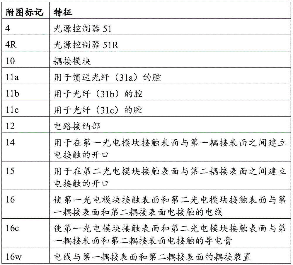

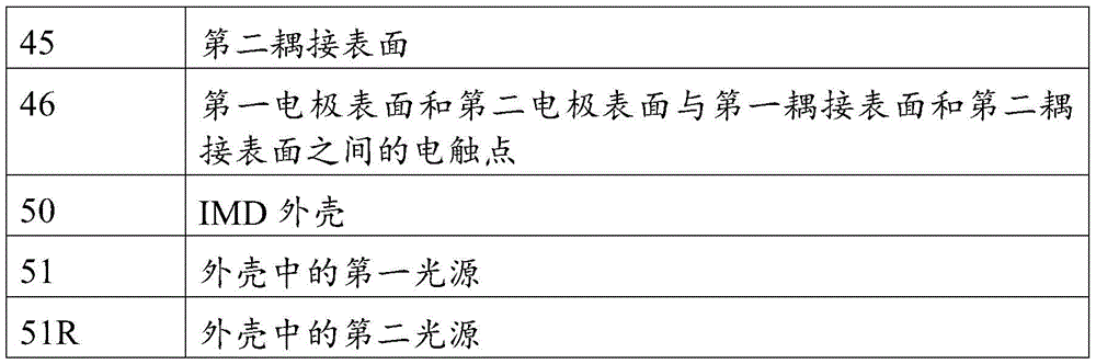
Claims (29)
Applications Claiming Priority (1)
| Application Number | Priority Date | Filing Date | Title |
|---|---|---|---|
| PCT/EP2017/071858 WO2019042553A1 (en) | 2017-08-31 | 2017-08-31 | Implantable electrode coupled to an optoelectronic device |
Publications (2)
| Publication Number | Publication Date |
|---|---|
| CN110785205A CN110785205A (en) | 2020-02-11 |
| CN110785205B true CN110785205B (en) | 2020-11-20 |
Family
ID=59745294
Family Applications (1)
| Application Number | Title | Priority Date | Filing Date |
|---|---|---|---|
| CN201780092435.5A Active CN110785205B (en) | 2017-08-31 | 2017-08-31 | Implantable electrodes coupled to optoelectronic devices |
Country Status (10)
| Country | Link |
|---|---|
| US (1) | US11052260B2 (en) |
| EP (1) | EP3471820B1 (en) |
| JP (1) | JP6830718B2 (en) |
| CN (1) | CN110785205B (en) |
| AU (1) | AU2017430127B2 (en) |
| BR (1) | BR112020002911A2 (en) |
| CA (1) | CA3072276C (en) |
| DK (1) | DK3471820T3 (en) |
| ES (1) | ES2748673T3 (en) |
| WO (1) | WO2019042553A1 (en) |
Families Citing this family (8)
| Publication number | Priority date | Publication date | Assignee | Title |
|---|---|---|---|---|
| US11484729B2 (en) * | 2019-04-15 | 2022-11-01 | Cornell University | Optical relay station-based implantable sensor modules |
| CA3147484C (en) | 2019-07-16 | 2023-01-03 | Synergia Medical | Active implantable medical device (aimd) comprising a transparent encapsulation |
| ES2922360T3 (en) | 2019-08-14 | 2022-09-13 | Synergia Medical | Polymeric optical fiber for active implantable medical devices |
| CN115003369B (en) | 2020-01-09 | 2023-06-23 | 赛纳吉亚医疗公司 | Active implantable stimulation device for on-demand stimulation of the vagus nerve |
| CA3170535C (en) | 2020-05-04 | 2023-08-08 | Pascal Doguet | Active implantable stimulating device for use with an mri-device |
| CN113013334A (en) * | 2021-02-05 | 2021-06-22 | 中山大学 | Photoelectric conversion device and preparation method, device and system thereof |
| JP2024511001A (en) * | 2021-03-24 | 2024-03-12 | シナジア メディカル | Active implantable medical devices (AIMDs) with in-situ optimization of power consumption |
| US12428543B2 (en) | 2021-05-18 | 2025-09-30 | Ticona Llc | Connected medical device containing a liquid crystalline polymer composition having a low dielectric constant |
Citations (5)
| Publication number | Priority date | Publication date | Assignee | Title |
|---|---|---|---|---|
| EP0377547A1 (en) * | 1989-01-06 | 1990-07-11 | Spectec S.A. | Opto-electronic prosthesis for the rehabilitation of the neuromotorically or neurosensorially handicapped using at least one light source and optical fibres for the stimulation of nerves or tissues, and process to use it |
| US6829509B1 (en) * | 2001-02-20 | 2004-12-07 | Biophan Technologies, Inc. | Electromagnetic interference immune tissue invasive system |
| CN102380170A (en) * | 2011-08-16 | 2012-03-21 | 中国科学院深圳先进技术研究院 | Implanted photoelectrode collecting, regulating and controlling device |
| WO2016131492A1 (en) * | 2015-02-20 | 2016-08-25 | Synergia Medical | Photovoltaic electrical stimulation device |
| WO2017004576A1 (en) * | 2015-07-02 | 2017-01-05 | The Board Of Trustees Of The University Of Illinois | Wireless optofluidic systems for programmable in vivo pharmacology and optogenetics |
Family Cites Families (12)
| Publication number | Priority date | Publication date | Assignee | Title |
|---|---|---|---|---|
| SE9301855D0 (en) * | 1993-06-01 | 1993-06-01 | Siemens-Elema Ab | MEDICAL SYSTEM |
| US20050268962A1 (en) * | 2000-04-27 | 2005-12-08 | Russell Gaudiana | Flexible Photovoltaic cells, systems and methods |
| US20020116028A1 (en) * | 2001-02-20 | 2002-08-22 | Wilson Greatbatch | MRI-compatible pacemaker with pulse carrying photonic catheter providing VOO functionality |
| US20020116033A1 (en) * | 2001-02-20 | 2002-08-22 | Wilson Greatbatch | Controllable, wearable MRI-compatible cardiac pacemaker with pulse carrying photonic catheter and VOO functionality |
| US6988001B2 (en) * | 2001-10-31 | 2006-01-17 | Biophan Technologies, Inc. | Hermetic component housing for photonic catheter |
| US6711440B2 (en) * | 2002-04-11 | 2004-03-23 | Biophan Technologies, Inc. | MRI-compatible medical device with passive generation of optical sensing signals |
| US6725092B2 (en) * | 2002-04-25 | 2004-04-20 | Biophan Technologies, Inc. | Electromagnetic radiation immune medical assist device adapter |
| US7395118B2 (en) * | 2003-09-25 | 2008-07-01 | Advanced Neuromodulation Systems, Inc. | System and method for implantable stimulation lead employing optical fibers |
| DE102005039183B4 (en) | 2005-08-18 | 2008-05-29 | Siemens Ag | Device for electrical stimulation of parts of the nervous system |
| US7883536B1 (en) * | 2007-01-19 | 2011-02-08 | Lockheed Martin Corporation | Hybrid optical-electrical probes |
| US8744568B2 (en) * | 2009-12-22 | 2014-06-03 | Boston Scientific Scimed, Inc. | Medical device with electroactive polymer powered by photovoltaic cell |
| WO2018068807A1 (en) * | 2016-10-10 | 2018-04-19 | Synergia Medical | Implantable medical device comprising an optical unit |
-
2017
- 2017-08-31 US US16/634,598 patent/US11052260B2/en active Active
- 2017-08-31 WO PCT/EP2017/071858 patent/WO2019042553A1/en not_active Ceased
- 2017-08-31 DK DK17758875T patent/DK3471820T3/en active
- 2017-08-31 JP JP2020511914A patent/JP6830718B2/en not_active Expired - Fee Related
- 2017-08-31 ES ES17758875T patent/ES2748673T3/en active Active
- 2017-08-31 BR BR112020002911-4A patent/BR112020002911A2/en not_active Application Discontinuation
- 2017-08-31 CN CN201780092435.5A patent/CN110785205B/en active Active
- 2017-08-31 EP EP17758875.3A patent/EP3471820B1/en active Active
- 2017-08-31 CA CA3072276A patent/CA3072276C/en active Active
- 2017-08-31 AU AU2017430127A patent/AU2017430127B2/en not_active Ceased
Patent Citations (5)
| Publication number | Priority date | Publication date | Assignee | Title |
|---|---|---|---|---|
| EP0377547A1 (en) * | 1989-01-06 | 1990-07-11 | Spectec S.A. | Opto-electronic prosthesis for the rehabilitation of the neuromotorically or neurosensorially handicapped using at least one light source and optical fibres for the stimulation of nerves or tissues, and process to use it |
| US6829509B1 (en) * | 2001-02-20 | 2004-12-07 | Biophan Technologies, Inc. | Electromagnetic interference immune tissue invasive system |
| CN102380170A (en) * | 2011-08-16 | 2012-03-21 | 中国科学院深圳先进技术研究院 | Implanted photoelectrode collecting, regulating and controlling device |
| WO2016131492A1 (en) * | 2015-02-20 | 2016-08-25 | Synergia Medical | Photovoltaic electrical stimulation device |
| WO2017004576A1 (en) * | 2015-07-02 | 2017-01-05 | The Board Of Trustees Of The University Of Illinois | Wireless optofluidic systems for programmable in vivo pharmacology and optogenetics |
Also Published As
| Publication number | Publication date |
|---|---|
| ES2748673T3 (en) | 2020-03-17 |
| AU2017430127A1 (en) | 2020-01-16 |
| US20200206514A1 (en) | 2020-07-02 |
| WO2019042553A1 (en) | 2019-03-07 |
| CN110785205A (en) | 2020-02-11 |
| EP3471820A1 (en) | 2019-04-24 |
| CA3072276A1 (en) | 2019-03-04 |
| EP3471820B1 (en) | 2019-08-14 |
| US11052260B2 (en) | 2021-07-06 |
| JP6830718B2 (en) | 2021-02-17 |
| DK3471820T3 (en) | 2019-10-28 |
| JP2020527997A (en) | 2020-09-17 |
| BR112020002911A2 (en) | 2020-07-28 |
| AU2017430127B2 (en) | 2020-03-05 |
| CA3072276C (en) | 2020-09-29 |
Similar Documents
| Publication | Publication Date | Title |
|---|---|---|
| CN110785205B (en) | Implantable electrodes coupled to optoelectronic devices | |
| US12324925B2 (en) | Implantable optical stimulation lead and methods of making and using | |
| US6711440B2 (en) | MRI-compatible medical device with passive generation of optical sensing signals | |
| JP6574322B1 (en) | Implantable medical device including an optical unit | |
| Alt et al. | Let there be light—optoprobes for neural implants | |
| JP5037618B2 (en) | Implantable medical device header with optical interface | |
| US8275432B2 (en) | Implantable optical sensor and method for manufacture | |
| US20190255335A1 (en) | Sealed implantable medical device and method of forming same | |
| CN114126705B (en) | Active Implantable Medical Device (AIMD) including a transparent enclosure | |
| US12023507B2 (en) | Systems and methods for flexible, high-density opto-electronic arrays | |
| EP2808056B1 (en) | Optical stimulation device | |
| US12446795B2 (en) | Enclosure for a wireless implantable device with embedded power source |
Legal Events
| Date | Code | Title | Description |
|---|---|---|---|
| PB01 | Publication | ||
| PB01 | Publication | ||
| SE01 | Entry into force of request for substantive examination | ||
| SE01 | Entry into force of request for substantive examination | ||
| GR01 | Patent grant | ||
| GR01 | Patent grant |