CN110766785B - Real-time positioning and three-dimensional reconstruction device and method for underground pipeline - Google Patents
Real-time positioning and three-dimensional reconstruction device and method for underground pipeline Download PDFInfo
- Publication number
- CN110766785B CN110766785B CN201910876751.2A CN201910876751A CN110766785B CN 110766785 B CN110766785 B CN 110766785B CN 201910876751 A CN201910876751 A CN 201910876751A CN 110766785 B CN110766785 B CN 110766785B
- Authority
- CN
- China
- Prior art keywords
- pipeline
- image
- camera
- crawling robot
- measurement unit
- Prior art date
- Legal status (The legal status is an assumption and is not a legal conclusion. Google has not performed a legal analysis and makes no representation as to the accuracy of the status listed.)
- Active
Links
Images


Classifications
-
- G—PHYSICS
- G06—COMPUTING OR CALCULATING; COUNTING
- G06T—IMAGE DATA PROCESSING OR GENERATION, IN GENERAL
- G06T17/00—Three dimensional [3D] modelling, e.g. data description of 3D objects
-
- G—PHYSICS
- G06—COMPUTING OR CALCULATING; COUNTING
- G06T—IMAGE DATA PROCESSING OR GENERATION, IN GENERAL
- G06T7/00—Image analysis
- G06T7/20—Analysis of motion
- G06T7/246—Analysis of motion using feature-based methods, e.g. the tracking of corners or segments
-
- G—PHYSICS
- G06—COMPUTING OR CALCULATING; COUNTING
- G06T—IMAGE DATA PROCESSING OR GENERATION, IN GENERAL
- G06T7/00—Image analysis
- G06T7/70—Determining position or orientation of objects or cameras
- G06T7/73—Determining position or orientation of objects or cameras using feature-based methods
-
- G—PHYSICS
- G06—COMPUTING OR CALCULATING; COUNTING
- G06V—IMAGE OR VIDEO RECOGNITION OR UNDERSTANDING
- G06V20/00—Scenes; Scene-specific elements
- G06V20/10—Terrestrial scenes
-
- Y—GENERAL TAGGING OF NEW TECHNOLOGICAL DEVELOPMENTS; GENERAL TAGGING OF CROSS-SECTIONAL TECHNOLOGIES SPANNING OVER SEVERAL SECTIONS OF THE IPC; TECHNICAL SUBJECTS COVERED BY FORMER USPC CROSS-REFERENCE ART COLLECTIONS [XRACs] AND DIGESTS
- Y02—TECHNOLOGIES OR APPLICATIONS FOR MITIGATION OR ADAPTATION AGAINST CLIMATE CHANGE
- Y02T—CLIMATE CHANGE MITIGATION TECHNOLOGIES RELATED TO TRANSPORTATION
- Y02T10/00—Road transport of goods or passengers
- Y02T10/10—Internal combustion engine [ICE] based vehicles
- Y02T10/40—Engine management systems
Landscapes
- Engineering & Computer Science (AREA)
- Physics & Mathematics (AREA)
- General Physics & Mathematics (AREA)
- Theoretical Computer Science (AREA)
- Multimedia (AREA)
- Computer Vision & Pattern Recognition (AREA)
- Computer Graphics (AREA)
- Geometry (AREA)
- Software Systems (AREA)
- Image Analysis (AREA)
- Length Measuring Devices By Optical Means (AREA)
Abstract
Description
技术领域Technical Field
本发明属于测绘技术领域,涉及一种地下管道实时定位与三维重建装置及方法,具体涉及一种基于地下管道爬行机器人及利用RGB-D相机和惯性测量单元 (IMU)进行地下管道实时定位与三维重建的装置及方法。The present invention belongs to the field of surveying and mapping technology, and relates to a device and method for real-time positioning and three-dimensional reconstruction of underground pipelines, and specifically to a device and method for real-time positioning and three-dimensional reconstruction of underground pipelines based on an underground pipeline crawling robot and using an RGB-D camera and an inertial measurement unit (IMU).
背景技术Background Art
地下管道(如城市排水管网)是“城市静脉”,是城市安全稳定运行的基础,是智慧城市建设的重要内容,现代化的地下管道系统成为衡量一个城市基础设施完善程度和城市管理水平的重要标志之一。管道检测是实现对地下管道精细化管理和预防性修复的前提,对维护城市功能正常运转,确保生命财产安全是十分必要的。比如污水和雨水管道承担着城市污水收集和雨水排除任务,其有效发挥功能是保障城市安全运行、保障生命财产安全的前提,因此,全国各大中城市都在大力建设“智慧水务”系统。Underground pipelines (such as urban drainage networks) are the "veins of the city", the basis for the safe and stable operation of the city, and an important part of the construction of smart cities. Modern underground pipeline systems have become one of the important indicators for measuring the degree of perfection of a city's infrastructure and the level of urban management. Pipeline detection is the prerequisite for achieving refined management and preventive repair of underground pipelines, and is very necessary for maintaining the normal operation of urban functions and ensuring the safety of life and property. For example, sewage and rainwater pipes are responsible for collecting urban sewage and removing rainwater. Their effective function is the prerequisite for ensuring the safe operation of the city and the safety of life and property. Therefore, all major and medium-sized cities across the country are vigorously building "smart water" systems.
由于地下管道的不可见性,总是等到发生事故时才被人们重视,造成大量的经济损失,甚至给生命财产安全带来隐患。目前,普遍公认的解决办法是在地下管道建设竣工和使用阶段应定期对管道现状进行测绘,对潜在的结构性和功能性损坏进行检测并及时修复。对管道现状进行测绘检测是进行精细化管理和预防性修复的前提。由于管道环境的特殊性复杂性,人员难以直接到达,常规测绘方法难以实施。国内外对地下管道检测机器人了较多研发,如特瑞升、雷迪世纪和中仪物联等公司的管道机器人代表了目前国内外产业界的最高水平。Due to the invisibility of underground pipelines, people always wait until an accident occurs before paying attention to them, causing huge economic losses and even posing hidden dangers to the safety of life and property. At present, the generally recognized solution is to regularly survey and map the status of underground pipelines during the completion and use stages of underground pipeline construction, detect potential structural and functional damage and repair them in a timely manner. Surveying and detecting the status of pipelines is a prerequisite for refined management and preventive repairs. Due to the particularity and complexity of the pipeline environment, it is difficult for personnel to reach directly, and conventional surveying methods are difficult to implement. There has been a lot of research and development on underground pipeline inspection robots at home and abroad. For example, pipeline robots from companies such as Terex, Radi Century and Zhongyi IoT represent the highest level of the industry at home and abroad.
但从管道检测服务行业来看,现有管道检测技术和装备有两大缺陷:However, from the perspective of the pipeline inspection service industry, the existing pipeline inspection technology and equipment have two major defects:
1)数据可视化效果不好,主要靠人眼判读2D图像数据(如CCTV视频(闭路电视监控系统Closed-Circuit Television)),而2D图像数据不能很好反映管道内3D真实情况,另外管道检测耗时耗力,需要较长时间暂停管道使用,甚至需要开挖路面;1) Data visualization is not good, mainly relying on human eyes to interpret 2D image data (such as CCTV video (Closed-Circuit Television)), and 2D image data cannot well reflect the real 3D situation in the pipeline. In addition, pipeline inspection is time-consuming and labor-intensive, requiring a long period of suspension of pipeline use, and even requiring excavation of the road surface;
2)在管道内缺乏实时定位系统,无法对检测数据进行空间定位,降低了数据的有效利用和系统整体效能发挥(如对决策的支持效率和自动化程度)。2) The lack of a real-time positioning system in the pipeline makes it impossible to spatially locate the detection data, which reduces the effective use of data and the overall effectiveness of the system (such as the support efficiency and degree of automation for decision-making).
发明内容Summary of the invention
为了解决上述技术问题,本发明提供了一种新型自动化、智能化地下管道实时定位与三维重建装置及方法。In order to solve the above technical problems, the present invention provides a novel automated and intelligent underground pipeline real-time positioning and three-dimensional reconstruction device and method.
本发明的装置所采用的技术方案是:一种地下管道实时定位与三维重建装置,其特征在于:由管道爬行机器人、处理器、RGB-D相机和惯性测量单元组成;The technical solution adopted by the device of the present invention is: a real-time positioning and three-dimensional reconstruction device for underground pipelines, characterized in that it is composed of a pipeline crawling robot, a processor, an RGB-D camera and an inertial measurement unit;
所述管道爬行机器人,用于在地下管道空间自主移动;The pipeline crawling robot is used to move autonomously in the underground pipeline space;
所述处理器,用于采集并处理RGB-D相机和惯性测量单元数据,计算出管道爬行机器人在地下管道中的实时位置,重建出地下管道的三维模型,最终控制管道爬行机器人的自主移动;The processor is used to collect and process the data of the RGB-D camera and the inertial measurement unit, calculate the real-time position of the pipeline crawling robot in the underground pipeline, reconstruct the three-dimensional model of the underground pipeline, and finally control the autonomous movement of the pipeline crawling robot;
所述RGB-D相机,用于所述管道爬行机器人在地下管道空间内外移动时采集彩色图像数据和深度图像数据;The RGB-D camera is used to collect color image data and depth image data when the pipeline crawling robot moves inside and outside the underground pipeline space;
所述RGB-D相机,用于所述管道爬行机器人在地下管道空间内外移动时采集加速度数据和陀螺仪数据;The RGB-D camera is used to collect acceleration data and gyroscope data when the pipeline crawling robot moves inside and outside the underground pipeline space;
所述处理器、RGB-D相机和惯性测量单元固定设置在所述管道爬行机器人上,并通过导线一一与所述管道爬行机器人中设置的中央处理器连接。The processor, RGB-D camera and inertial measurement unit are fixedly arranged on the pipeline crawling robot and are connected one by one to the central processing unit arranged in the pipeline crawling robot through wires.
本发明的方法所采用的技术方案是:一种地下管道实时定位与三维重建方法,其特征在于,包括以下步骤:The technical solution adopted by the method of the present invention is: a method for real-time positioning and three-dimensional reconstruction of underground pipelines, characterized in that it includes the following steps:
步骤1:标定RGB-D相机内参以及相机和惯性测量单元的相对位置和姿态信息;Step 1: Calibrate the RGB-D camera internal parameters and the relative position and attitude information of the camera and inertial measurement unit;
步骤2:管道爬行机器人在管道空间自主移动,RGB-D相机和惯性测量单元实时获取数据;Step 2: The pipeline crawling robot moves autonomously in the pipeline space, and the RGB-D camera and inertial measurement unit acquire data in real time;
步骤3:计算确定管道爬行机器人在数据采集移动过程中的精确位置;Step 3: Calculate and determine the precise position of the pipeline crawling robot during the data collection movement process;
步骤4:利用步骤3确定的管道爬行机器人的位置和步骤1确定的RGB-D 相机和惯性测量单元的相对位置和姿态信息,恢复场景的三维重建模型;所述三维重建包括管道的三维尺寸,几何形状和颜色纹理。Step 4: Using the position of the pipeline crawling robot determined in step 3 and the relative position and posture information of the RGB-D camera and the inertial measurement unit determined in step 1, restore the three-dimensional reconstruction model of the scene; the three-dimensional reconstruction includes the three-dimensional size, geometric shape and color texture of the pipeline.
作为优选,步骤2中所述RGB-D相机和惯性测量单元实时获取数据,包括所述管道爬行机器人的运动加速度和角速度、管道空间内2D图像数据和深度图像数据。Preferably, the RGB-D camera and inertial measurement unit in step 2 acquire data in real time, including the motion acceleration and angular velocity of the pipeline crawling robot, 2D image data and depth image data in the pipeline space.
作为优选,步骤3的具体实现包括以下子步骤:Preferably, the specific implementation of step 3 includes the following sub-steps:
步骤3.1:采用视觉特征跟踪策略建立一套特征点管理策略来有效表示每一帧图像中特征点所在的位置,通过IMU预积分策略使高频IMU数据与低频视觉图像数据配准起来;Step 3.1: Use the visual feature tracking strategy to establish a set of feature point management strategies to effectively represent the location of the feature points in each frame image, and use the IMU pre-integration strategy to align the high-frequency IMU data with the low-frequency visual image data;
所述采用视觉特征跟踪策略建立一套特征点管理策略来有效表示每一帧图像中特征点所在的位置,具体实现包括以下子步骤:The visual feature tracking strategy is used to establish a set of feature point management strategies to effectively represent the location of the feature points in each frame of the image. The specific implementation includes the following sub-steps:
步骤3.1.1:将彩色图像转换为灰度图像,然后在初始灰度图像上提取预定数量N的FAST特征点;Step 3.1.1: Convert the color image into a grayscale image, and then extract a predetermined number N of FAST feature points on the initial grayscale image;
步骤3.1.2:利用光流法在第二张灰度图像上跟踪初始灰度图像上的FAST 特征点,得到第二张图像上跟踪成功的特征点;若第二张图像上跟踪成功的特征点少于预定数量N,则在第二张图像上继续提取FAST特征点,使得特征点数量保持稳定;Step 3.1.2: Use the optical flow method to track the FAST feature points on the initial grayscale image on the second grayscale image to obtain the successfully tracked feature points on the second image; if the successfully tracked feature points on the second image are less than the predetermined number N, continue to extract FAST feature points on the second image so that the number of feature points remains stable;
步骤3.1.3:重复步骤3.1.2,依次在当前图像上跟踪上一张图像的特征点,并提取新特征点,使得特征点总数不变;Step 3.1.3: Repeat step 3.1.2, track the feature points of the previous image on the current image in turn, and extract new feature points so that the total number of feature points remains unchanged;
步骤3.2:通过多视图几何中的视觉SFM来求解相机位置和姿态信息和场景几何结构,从而构建稀疏的初始地图;通过将带有尺度的IMU预积分和不带尺度的视觉SFM关联起来,从而恢复陀螺仪的偏差、系统的速度、重力矢量以及度量尺度;Step 3.2: Use the visual SFM in multi-view geometry to solve the camera position and attitude information and the scene geometry to build a sparse initial map; recover the gyroscope bias, system velocity, gravity vector, and metric scale by associating the scaled IMU pre-integration with the scale-free visual SFM;
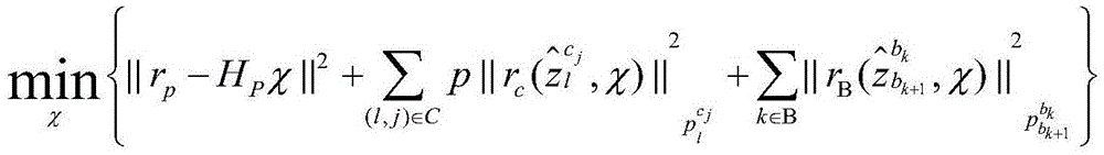
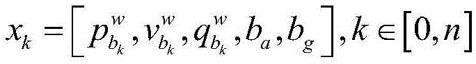
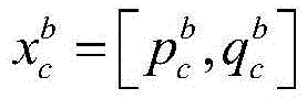
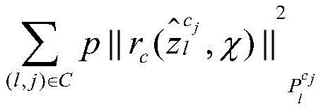
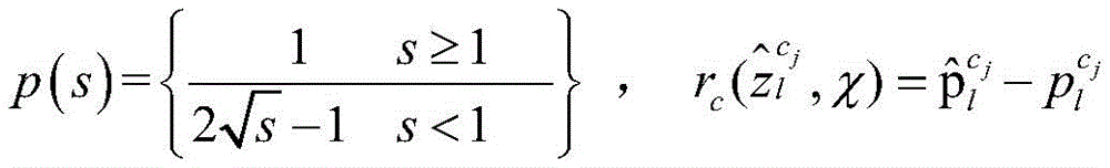
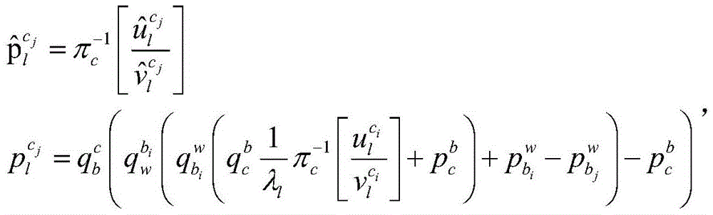
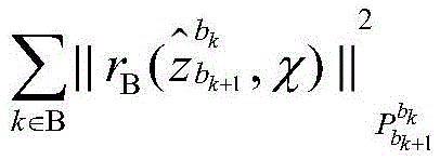
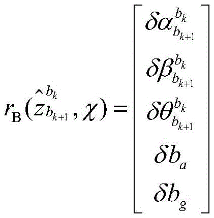
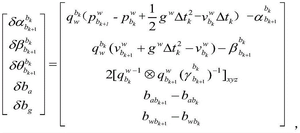
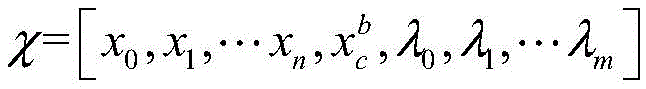
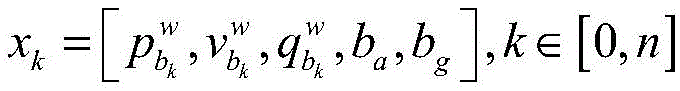
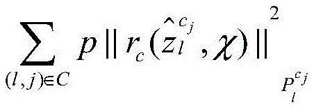
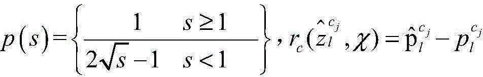
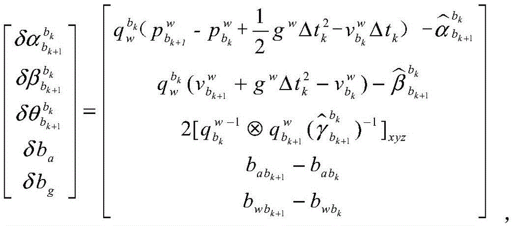
步骤3.3:进行相机位置和姿态信息和场景几何结构的优化计算,构建包含三个残差项的优化函数,分别是边缘化的先验信息、视觉的重投影误差项和IMU 的测量残差项。Step 3.3: Perform optimization calculations on the camera position and attitude information and the scene geometry, and construct an optimization function containing three residual terms, namely, marginalized prior information, visual reprojection error term, and IMU measurement residual term.
通过优化函数来进行优化计算,优化函数为:The optimization calculation is performed through the optimization function, and the optimization function is:

其中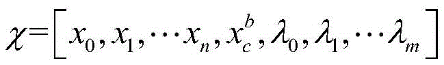
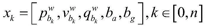
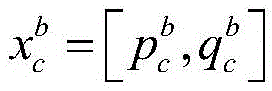
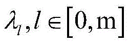
||rp-HPχ||2为边缘化的先验信息,rp-HPχ为边缘化残差,rp表示边缘化先验信息,HP为边缘化信息矩阵;||r p -H P χ|| 2 is the marginalized prior information, r p -H P χ is the marginalized residual, r p represents the marginalized prior information, and H P is the marginalized information matrix;
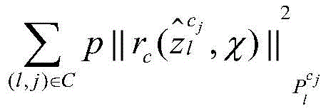
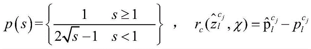
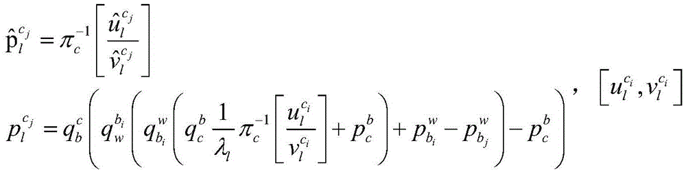


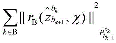


式中gw表示重力向量,[·]表示四元数的向量部分,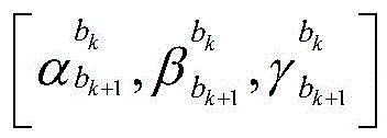
作为优选,利用步骤3确定的管道爬行机器人的相机相对位置和姿态信息,场景的几何结构以及步骤2采集的深度图像数据恢复地下管道的真实三维场景信息,并进行颜色纹理贴图。Preferably, the camera relative position and posture information of the pipeline crawling robot determined in step 3, the geometric structure of the scene and the depth image data collected in step 2 are used to restore the real three-dimensional scene information of the underground pipeline, and perform color texture mapping.
与现有技术相比,本发明的有益效果是:Compared with the prior art, the present invention has the following beneficial effects:
(1)本发明的管道爬行机器人装备具有在管道内外等复杂环境中无缝定位能力。无缝定位带来的益处是:机器人能按照规划的路径自主移动,自动化采集数据;根据采集的数据,机器人可以自动生成路径轨迹。(1) The pipeline crawling robot equipment of the present invention has the ability to seamlessly locate in complex environments such as inside and outside the pipeline. The benefits of seamless positioning are: the robot can move autonomously according to the planned path and automatically collect data; based on the collected data, the robot can automatically generate a path trajectory.
(2)本发明的管道爬行机器人装备和方法数据采集自动化程度高,采集效率高,不需人工操作。本发明方法集成了RGB-D相机和视觉惯性测量单元两个传感器,能够获得管道爬行机器人在地下管道空间内外移动时采集彩色图像数据,深度图像数据,加速度数据以及陀螺仪数据。和现有的装备与方法相比(如通过人工遥控采集CCTV摄像头数据),数据采集过程自动化程度显著提高,计算机自动化采集和处理确保了数据的准确性和精确性,多传感器融合方法提高了数据的丰富性、多样性,能够同时采集多维数据。(2) The data collection of the pipeline crawling robot equipment and method of the present invention is highly automated and efficient, and does not require manual operation. The method of the present invention integrates two sensors, an RGB-D camera and a visual inertial measurement unit, and can obtain color image data, depth image data, acceleration data, and gyroscope data when the pipeline crawling robot moves inside and outside the underground pipeline space. Compared with existing equipment and methods (such as collecting CCTV camera data through manual remote control), the automation level of the data collection process is significantly improved, computer automated collection and processing ensures the accuracy and precision of the data, and the multi-sensor fusion method improves the richness and diversity of the data, and can collect multi-dimensional data at the same time.
(3)本发明的管道爬行机器人装备和方法数据处理智能化程度高,精确度高,不需人工操作。本发明装备和方法采用多传感器采集管道空间中多维数据,从而计算爬行机器人在地下管道中的实时位置,生成带有地理坐标的管道现状类型,提取管道几何形状和属性现状等信息。和现有的装备与方法相比(如通过人工遥控采集CCTV摄像头数据),计算爬行机器人在地下管道内的实时位姿轨迹和恢复地下管道三维模型过程自动化程度显著提高,计算机自动化处理确保了检测结果的完整性和精确性,大大减少了人工现场作业的需求。(3) The data processing of the pipeline crawling robot equipment and method of the present invention is highly intelligent and accurate, and does not require manual operation. The equipment and method of the present invention use multiple sensors to collect multi-dimensional data in the pipeline space, thereby calculating the real-time position of the crawling robot in the underground pipeline, generating the current type of the pipeline with geographic coordinates, and extracting information such as the geometric shape and property status of the pipeline. Compared with existing equipment and methods (such as collecting CCTV camera data through manual remote control), the degree of automation of calculating the real-time position trajectory of the crawling robot in the underground pipeline and restoring the three-dimensional model of the underground pipeline is significantly improved, and computer automated processing ensures the integrity and accuracy of the detection results, greatly reducing the need for manual on-site operations.
附图说明BRIEF DESCRIPTION OF THE DRAWINGS
图1为本发明实施例的方法流程图;FIG1 is a flow chart of a method according to an embodiment of the present invention;
图2为本发明实施例中获得的一个地下管道内空间的视觉数据图,包括彩色图像和深度图像;FIG2 is a visual data diagram of a space inside an underground pipeline obtained in an embodiment of the present invention, including a color image and a depth image;
图3为本发明实施例中计算得到的爬行机器人在地下管道内的实时位置轨迹和地下管道的稀疏几何结构;FIG3 is a real-time position trajectory of a crawling robot in an underground pipeline and a sparse geometric structure of the underground pipeline calculated in an embodiment of the present invention;
图4和图5为本发明实施例中恢复的场景三维重建模型。FIG. 4 and FIG. 5 are restored 3D reconstruction models of the scene in an embodiment of the present invention.
具体实施方式DETAILED DESCRIPTION
为了便于本领域普通技术人员理解和实施本发明,下面结合附图及实施例对本发明作进一步的详细描述,应当理解,此处所描述的实施示例仅用于说明和解释本发明,并不用于限定本发明。In order to facilitate ordinary technicians in the field to understand and implement the present invention, the present invention is further described in detail below in conjunction with the accompanying drawings and embodiments. It should be understood that the implementation examples described herein are only used to illustrate and explain the present invention, and are not used to limit the present invention.
本发明提供的一种地下管道实时定位与三维重建装置,由管道爬行机器人、处理器、RGB-D相机和惯性测量单元组成;The present invention provides an underground pipeline real-time positioning and three-dimensional reconstruction device, which is composed of a pipeline crawling robot, a processor, an RGB-D camera and an inertial measurement unit;
管道爬行机器人,用于在地下管道空间自主移动;Pipeline crawling robot, used to move autonomously in underground pipeline space;
处理器,用于采集并处理RGB-D相机和惯性测量单元数据,计算出管道爬行机器人在地下管道中的实时位置,重建出地下管道的三维模型,最终控制管道爬行机器人的自主移动;The processor is used to collect and process the data from the RGB-D camera and the inertial measurement unit, calculate the real-time position of the pipeline crawling robot in the underground pipeline, reconstruct the three-dimensional model of the underground pipeline, and finally control the autonomous movement of the pipeline crawling robot;
RGB-D相机,用于管道爬行机器人在地下管道空间内外移动时采集彩色图像数据和深度图像数据;RGB-D camera, used to collect color image data and depth image data when the pipeline crawling robot moves in and out of the underground pipeline space;
RGB-D相机,用于管道爬行机器人在地下管道空间内外移动时采集加速度数据和陀螺仪数据;RGB-D camera, used to collect acceleration and gyroscope data when the pipeline crawling robot moves in and out of the underground pipeline space;
处理器、RGB-D相机和惯性测量单元固定设置在管道爬行机器人上,并通过导线一一与管道爬行机器人中设置的中央处理器连接。The processor, RGB-D camera and inertial measurement unit are fixedly arranged on the pipeline crawling robot and are connected one by one to the central processing unit arranged in the pipeline crawling robot through wires.
请见图1,本发明提供的一种地下管道实时定位与三维重建方法,包括以下步骤:Please see FIG1 , a method for real-time positioning and three-dimensional reconstruction of underground pipelines provided by the present invention includes the following steps:
步骤1:标定RGB-D相机内参以及相机和惯性测量单元的相对位置和姿态信息;Step 1: Calibrate the RGB-D camera internal parameters and the relative position and attitude information of the camera and inertial measurement unit;
步骤2:管道爬行机器人在管道空间自主移动,RGB-D相机和惯性测量单元实时获取数据;Step 2: The pipeline crawling robot moves autonomously in the pipeline space, and the RGB-D camera and inertial measurement unit acquire data in real time;
本实施例中,RGB-D相机和惯性测量单元实时获取数据,包括管道爬行机器人的运动加速度和角速度、管道空间内2D图像数据和深度图像数据。In this embodiment, the RGB-D camera and the inertial measurement unit acquire data in real time, including the motion acceleration and angular velocity of the pipeline crawling robot, and the 2D image data and depth image data in the pipeline space.
步骤3:计算确定管道爬行机器人在数据采集移动过程中的精确位置;Step 3: Calculate and determine the precise position of the pipeline crawling robot during the data collection movement process;
本实施例的具体实现包括以下子步骤:The specific implementation of this embodiment includes the following sub-steps:
步骤3.1:采用视觉特征跟踪策略建立一套特征点管理策略来有效表示每一帧图像中特征点所在的位置,通过IMU预积分策略使高频IMU数据与低频视觉图像数据配准起来;Step 3.1: Use the visual feature tracking strategy to establish a set of feature point management strategies to effectively represent the location of the feature points in each frame image, and use the IMU pre-integration strategy to align the high-frequency IMU data with the low-frequency visual image data;
采用视觉特征跟踪策略建立一套特征点管理策略来有效表示每一帧图像中特征点所在的位置,具体实现包括以下子步骤:A set of feature point management strategies is established using visual feature tracking strategies to effectively represent the location of feature points in each frame of the image. The specific implementation includes the following sub-steps:
步骤3.1.1:将彩色图像转换为灰度图像,然后在初始灰度图像上提取预定数量N(本实施例取500个)的FAST特征点;Step 3.1.1: Convert the color image into a grayscale image, and then extract a predetermined number N (500 in this embodiment) of FAST feature points on the initial grayscale image;
步骤3.1.2:利用光流法在第二张灰度图像上跟踪初始灰度图像上的FAST 特征点,得到第二张图像上跟踪成功的特征点;若第二张图像上跟踪成功的特征点少于预定数量N(本实施例取500个),则在第二张图像上继续提取FAST特征点,使得特征点数量保持稳定;Step 3.1.2: Use the optical flow method to track the FAST feature points on the initial grayscale image on the second grayscale image to obtain the successfully tracked feature points on the second image; if the number of successfully tracked feature points on the second image is less than a predetermined number N (500 in this embodiment), continue to extract FAST feature points on the second image so that the number of feature points remains stable;
步骤3.1.3:重复步骤3.1.2,依次在当前图像上跟踪上一张图像的特征点,并提取新特征点,使得特征点总数不变;Step 3.1.3: Repeat step 3.1.2, track the feature points of the previous image on the current image in turn, and extract new feature points so that the total number of feature points remains unchanged;
步骤3.2:通过多视图几何中的视觉SFM来求解相机位置和姿态信息和场景几何结构,从而构建稀疏的初始地图;通过将带有尺度的IMU预积分和不带尺度的视觉SFM关联起来,从而恢复陀螺仪的偏差、系统的速度、重力矢量以及度量尺度;Step 3.2: Use the visual SFM in multi-view geometry to solve the camera position and attitude information and the scene geometry to build a sparse initial map; recover the gyroscope bias, system velocity, gravity vector, and metric scale by associating the scaled IMU pre-integration with the scale-free visual SFM;
步骤3.3:进行相机位置和姿态信息和场景几何结构的优化计算,构建包含三个残差项的优化函数,分别是边缘化的先验信息、视觉的重投影误差项和IMU 的测量残差项。Step 3.3: Perform optimization calculations on the camera position and attitude information and the scene geometry, and construct an optimization function containing three residual terms, namely, marginalized prior information, visual reprojection error term, and IMU measurement residual term.
通过优化函数来进行优化计算,优化函数为:The optimization calculation is performed through the optimization function, and the optimization function is:
其中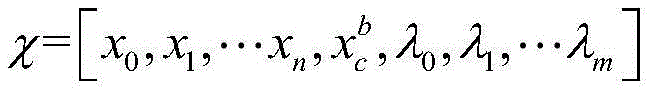


||rp-HPχ||2为边缘化的先验信息,rp-HPχ为边缘化残差,rp表示边缘化先验信息,HP为边缘化信息矩阵;||r p -H P χ|| 2 is the marginalized prior information, r p -H P χ is the marginalized residual, r p represents the marginalized prior information, and H P is the marginalized information matrix;


式中gw表示重力向量,[·]表示四元数的向量部分,
目前,管道爬行机器人在地下管道内的定位方案只有测量线缆长度一种方式,通过线缆盘设备测量线缆长度只能获得一维数据,并且一维数据所代表的的实际含义只是管道爬行机器人所行驶的路程长度,并不知道管道爬行机器人在地下管道内的真实三维坐标,而本申请方案相比于现有技术,可以获得管道爬行机器人在地下管道内的实时三维位置信息。At present, the only positioning solution for pipeline crawling robots in underground pipelines is to measure the cable length. Measuring the cable length through cable reel equipment can only obtain one-dimensional data, and the actual meaning of the one-dimensional data is only the distance traveled by the pipeline crawling robot. The real three-dimensional coordinates of the pipeline crawling robot in the underground pipeline are unknown. Compared with the prior art, the present application solution can obtain real-time three-dimensional position information of the pipeline crawling robot in the underground pipeline.
另外目前地下管道的检测主要还是依赖人眼观察视频图像来判别地下管道的缺陷,但是用二维视频图像来表示地下三维管道肯定会带来信息的丢失,导致地下管道信息不直观,人眼判别不可靠。本方案通过RGB-D相机和惯性测量单元可以重建出地下管道的真实三维模型,使得地下管道的检测如身临其境一般。In addition, the current detection of underground pipelines still mainly relies on human eyes to observe video images to identify the defects of underground pipelines. However, using two-dimensional video images to represent underground three-dimensional pipelines will definitely lead to information loss, resulting in unintuitive underground pipeline information and unreliable human eye judgment. This solution can reconstruct the real three-dimensional model of underground pipelines through RGB-D cameras and inertial measurement units, making the detection of underground pipelines as immersive as being there.
步骤4:利用步骤3确定的管道爬行机器人的位置和步骤1确定的RGB-D 相机和惯性测量单元的相对位置和姿态信息,恢复场景的三维重建模型;三维重建包括管道的三维尺寸,几何形状和颜色纹理。Step 4: Using the position of the pipeline crawling robot determined in step 3 and the relative position and posture information of the RGB-D camera and the inertial measurement unit determined in step 1, restore the three-dimensional reconstruction model of the scene; the three-dimensional reconstruction includes the three-dimensional size, geometric shape and color texture of the pipeline.
本实施例中,利用步骤3确定的管道爬行机器人的相机相对位置和姿态信息,场景的几何结构以及步骤2采集的深度图像数据恢复地下管道的真实三维场景信息,并进行颜色纹理贴图。In this embodiment, the camera relative position and posture information of the pipeline crawling robot determined in step 3, the geometric structure of the scene and the depth image data collected in step 2 are used to restore the real three-dimensional scene information of the underground pipeline, and perform color texture mapping.
图2为本发明实施例中获得的一个地下管道内空间的视觉数据图,包括彩色图像和深度图像。FIG. 2 is a visual data diagram of a space inside an underground pipeline obtained in an embodiment of the present invention, including a color image and a depth image.
图3为本发明实施例中计算得到的爬行机器人在地下管道内的实时位置轨迹和地下管道的稀疏几何结构。FIG3 is a diagram showing the real-time position trajectory of the crawling robot in the underground pipeline and the sparse geometric structure of the underground pipeline calculated in an embodiment of the present invention.
图4和图5为本发明实施例中恢复的场景三维重建模型。FIG. 4 and FIG. 5 are restored 3D reconstruction models of the scene in an embodiment of the present invention.
本发明具有在地下管道内外等复杂环境中无缝定位、管道空间数据自动采集、以及管道几何形状和属性现状信息等自动识别和提取等功能,是一种多传感器融合的机器人复杂环境无缝定位、自动化数据采集和智能化目标识别方法和机器人智能装备。The present invention has the functions of seamless positioning in complex environments such as inside and outside underground pipelines, automatic collection of pipeline spatial data, and automatic identification and extraction of pipeline geometric shape and attribute status information. It is a multi-sensor fusion robot complex environment seamless positioning, automatic data collection and intelligent target recognition method and robot intelligent equipment.
应当理解的是,本说明书未详细阐述的部分均属于现有技术。It should be understood that parts not elaborated in detail in this specification belong to the prior art.
应当理解的是,上述针对较佳实施例的描述较为详细,并不能因此而认为是对本发明专利保护范围的限制,本领域的普通技术人员在本发明的启示下,在不脱离本发明权利要求所保护的范围情况下,还可以做出替换或变形,均落入本发明的保护范围之内,本发明的请求保护范围应以所附权利要求为准。It should be understood that the above description of the preferred embodiment is relatively detailed and cannot be regarded as limiting the scope of patent protection of the present invention. Under the enlightenment of the present invention, ordinary technicians in this field can also make substitutions or modifications without departing from the scope of protection of the claims of the present invention, which all fall within the scope of protection of the present invention. The scope of protection requested for the present invention shall be based on the attached claims.
Claims (4)


Priority Applications (1)
| Application Number | Priority Date | Filing Date | Title |
|---|---|---|---|
| CN201910876751.2A CN110766785B (en) | 2019-09-17 | 2019-09-17 | Real-time positioning and three-dimensional reconstruction device and method for underground pipeline |
Applications Claiming Priority (1)
| Application Number | Priority Date | Filing Date | Title |
|---|---|---|---|
| CN201910876751.2A CN110766785B (en) | 2019-09-17 | 2019-09-17 | Real-time positioning and three-dimensional reconstruction device and method for underground pipeline |
Publications (2)
| Publication Number | Publication Date |
|---|---|
| CN110766785A CN110766785A (en) | 2020-02-07 |
| CN110766785B true CN110766785B (en) | 2023-05-05 |
Family
ID=69329935
Family Applications (1)
| Application Number | Title | Priority Date | Filing Date |
|---|---|---|---|
| CN201910876751.2A Active CN110766785B (en) | 2019-09-17 | 2019-09-17 | Real-time positioning and three-dimensional reconstruction device and method for underground pipeline |
Country Status (1)
| Country | Link |
|---|---|
| CN (1) | CN110766785B (en) |
Families Citing this family (8)
| Publication number | Priority date | Publication date | Assignee | Title |
|---|---|---|---|---|
| CN113436310A (en) * | 2020-03-23 | 2021-09-24 | 南京科沃斯机器人技术有限公司 | Scene establishing method, system and device and self-moving robot |
| CN112179373A (en) * | 2020-08-21 | 2021-01-05 | 同济大学 | A kind of measurement method of visual odometer and visual odometer |
| CN112529957B (en) * | 2020-12-08 | 2024-08-23 | 北京地平线信息技术有限公司 | Method and device for determining pose of image pickup device, storage medium and electronic device |
| CN113029023A (en) * | 2021-03-01 | 2021-06-25 | 李柏松 | Wall-climbing robot, working method and three-dimensional health diagnosis method for large equipment |
| CN113091733A (en) * | 2021-03-15 | 2021-07-09 | 武汉大学 | A real-time positioning device and method based on the fusion of millimeter wave radar and IMU |
| CN114991298B (en) * | 2022-06-23 | 2023-06-06 | 华中科技大学 | Urban drainage pipeline detection and dredging intelligent robot and working method |
| WO2024077084A1 (en) * | 2022-10-04 | 2024-04-11 | Nutech Ventures | Dual-function depth camera array for inline 3d reconstruction of complex pipelines |
| CN120445185B (en) * | 2025-07-09 | 2025-10-21 | 北京大学 | Track reduction and map reconstruction method capable of solving time drift error and application |
Citations (5)
| Publication number | Priority date | Publication date | Assignee | Title |
|---|---|---|---|---|
| CN106597566A (en) * | 2016-12-27 | 2017-04-26 | 广东技术师范学院 | Non-excavation underground pipeline detection system and realization method thereof |
| CN108846860A (en) * | 2018-04-25 | 2018-11-20 | 中国矿业大学(北京) | A kind of damaged cylindrical drainage pipeline inner wall three-dimensional rebuilding method |
| CN109544679A (en) * | 2018-11-09 | 2019-03-29 | 深圳先进技术研究院 | The three-dimensional rebuilding method of inner wall of the pipe |
| CN109658449A (en) * | 2018-12-03 | 2019-04-19 | 华中科技大学 | A kind of indoor scene three-dimensional rebuilding method based on RGB-D image |
| CN110174136A (en) * | 2019-05-07 | 2019-08-27 | 武汉大学 | A kind of underground piping intelligent measurement robot and intelligent detecting method |
Family Cites Families (3)
| Publication number | Priority date | Publication date | Assignee | Title |
|---|---|---|---|---|
| US20120300020A1 (en) * | 2011-05-27 | 2012-11-29 | Qualcomm Incorporated | Real-time self-localization from panoramic images |
| KR101850027B1 (en) * | 2011-12-08 | 2018-04-24 | 한국전자통신연구원 | Real-time 3-dimension actual environment reconstruction apparatus and method |
| US9251590B2 (en) * | 2013-01-24 | 2016-02-02 | Microsoft Technology Licensing, Llc | Camera pose estimation for 3D reconstruction |
-
2019
- 2019-09-17 CN CN201910876751.2A patent/CN110766785B/en active Active
Patent Citations (5)
| Publication number | Priority date | Publication date | Assignee | Title |
|---|---|---|---|---|
| CN106597566A (en) * | 2016-12-27 | 2017-04-26 | 广东技术师范学院 | Non-excavation underground pipeline detection system and realization method thereof |
| CN108846860A (en) * | 2018-04-25 | 2018-11-20 | 中国矿业大学(北京) | A kind of damaged cylindrical drainage pipeline inner wall three-dimensional rebuilding method |
| CN109544679A (en) * | 2018-11-09 | 2019-03-29 | 深圳先进技术研究院 | The three-dimensional rebuilding method of inner wall of the pipe |
| CN109658449A (en) * | 2018-12-03 | 2019-04-19 | 华中科技大学 | A kind of indoor scene three-dimensional rebuilding method based on RGB-D image |
| CN110174136A (en) * | 2019-05-07 | 2019-08-27 | 武汉大学 | A kind of underground piping intelligent measurement robot and intelligent detecting method |
Non-Patent Citations (3)
| Title |
|---|
| Nico Cornelis,etc.3D Urban Scene Modeling Integrating Recognition and Reconstruction.《International Journal of Computer Vision》.2007,第78卷121–141. * |
| 王聪,等.基于惯性导航与立体视觉的风管清扫机器人同时定位与地图创建方法.《机械工程学报》.2013,第49卷(第23期),59-67. * |
| 胡媛媛,杨霞.基于机器人的管道内壁三维重建技术研究.《工业仪表与自动化装置》.2016,(第04期), 121-124 . * |
Also Published As
| Publication number | Publication date |
|---|---|
| CN110766785A (en) | 2020-02-07 |
Similar Documents
| Publication | Publication Date | Title |
|---|---|---|
| CN110766785B (en) | Real-time positioning and three-dimensional reconstruction device and method for underground pipeline | |
| Chen et al. | 3D global mapping of large-scale unstructured orchard integrating eye-in-hand stereo vision and SLAM | |
| CN110097553B (en) | Semantic mapping system based on real-time positioning mapping and 3D semantic segmentation | |
| CN109544679B (en) | Three-dimensional reconstruction method for inner wall of pipeline | |
| CN108052103B (en) | Simultaneous localization and map construction method of inspection robot in underground space based on deep inertial odometry | |
| CN103400392B (en) | Binocular vision navigation system and method based on Intelligent Mobile Robot | |
| CN107167139A (en) | A kind of Intelligent Mobile Robot vision positioning air navigation aid and system | |
| CN115900710A (en) | Navigation method of dynamic environment based on visual information | |
| Shim et al. | Remote robotic system for 3D measurement of concrete damage in tunnel with ground vehicle and manipulator | |
| CN118758287A (en) | A navigation method and system for a building inspection robot based on no prior map | |
| WO2015024407A1 (en) | Power robot based binocular vision navigation system and method based on | |
| CN113175929B (en) | UPF-based spatial non-cooperative target relative pose estimation method | |
| CN110992487B (en) | Fast 3D map reconstruction device and reconstruction method for handheld aircraft fuel tank | |
| CN111339826B (en) | A linear sensor network framework detection system for landslide UAV | |
| CN115272596A (en) | A multi-sensor fusion SLAM method for monotonous and textureless large scenes | |
| CN111862146B (en) | Target object positioning method and device | |
| CN116222543A (en) | Multi-sensor fusion map construction method and system for robot environment perception | |
| CN116824080A (en) | Method for realizing SLAM point cloud mapping of power transmission corridor based on multi-sensor fusion | |
| CN105373130A (en) | Special device accident on-site information detection system based on stereo modeling | |
| CN110223351A (en) | A kind of depth camera localization method based on convolutional neural networks | |
| CN115307646A (en) | Multi-sensor fusion robot positioning method, system and device | |
| CN118570411A (en) | Building three-dimensional reconstruction and crack detection method, system, terminal and medium | |
| CN118628573A (en) | A robot online localization and mapping method for underwater vision-degraded scenes | |
| CN114529603B (en) | An odometry method based on the fusion of laser SLAM and monocular vision SLAM | |
| CN114332362A (en) | Inclinometry monitoring device and method for coupling optical positioning and real-time updating |
Legal Events
| Date | Code | Title | Description |
|---|---|---|---|
| PB01 | Publication | ||
| PB01 | Publication | ||
| SE01 | Entry into force of request for substantive examination | ||
| SE01 | Entry into force of request for substantive examination | ||
| GR01 | Patent grant | ||
| GR01 | Patent grant |