CN110732083A - Medical connector and pulse generator for connecting medical instruments - Google Patents
Medical connector and pulse generator for connecting medical instruments Download PDFInfo
- Publication number
- CN110732083A CN110732083A CN201810803255.XA CN201810803255A CN110732083A CN 110732083 A CN110732083 A CN 110732083A CN 201810803255 A CN201810803255 A CN 201810803255A CN 110732083 A CN110732083 A CN 110732083A
- Authority
- CN
- China
- Prior art keywords
- hole
- threading
- elastic contact
- connector
- medical
- Prior art date
- Legal status (The legal status is an assumption and is not a legal conclusion. Google has not performed a legal analysis and makes no representation as to the accuracy of the status listed.)
- Pending
Links
Images


Classifications
-
- A—HUMAN NECESSITIES
- A61—MEDICAL OR VETERINARY SCIENCE; HYGIENE
- A61N—ELECTROTHERAPY; MAGNETOTHERAPY; RADIATION THERAPY; ULTRASOUND THERAPY
- A61N1/00—Electrotherapy; Circuits therefor
- A61N1/18—Applying electric currents by contact electrodes
- A61N1/32—Applying electric currents by contact electrodes alternating or intermittent currents
- A61N1/36—Applying electric currents by contact electrodes alternating or intermittent currents for stimulation
- A61N1/3605—Implantable neurostimulators for stimulating central or peripheral nerve system
- A61N1/36053—Implantable neurostimulators for stimulating central or peripheral nerve system adapted for vagal stimulation
-
- A—HUMAN NECESSITIES
- A61—MEDICAL OR VETERINARY SCIENCE; HYGIENE
- A61N—ELECTROTHERAPY; MAGNETOTHERAPY; RADIATION THERAPY; ULTRASOUND THERAPY
- A61N1/00—Electrotherapy; Circuits therefor
- A61N1/18—Applying electric currents by contact electrodes
- A61N1/32—Applying electric currents by contact electrodes alternating or intermittent currents
- A61N1/36—Applying electric currents by contact electrodes alternating or intermittent currents for stimulation
- A61N1/3605—Implantable neurostimulators for stimulating central or peripheral nerve system
- A61N1/36125—Details of circuitry or electric components
Landscapes
- Health & Medical Sciences (AREA)
- Neurology (AREA)
- Neurosurgery (AREA)
- Engineering & Computer Science (AREA)
- Biomedical Technology (AREA)
- Nuclear Medicine, Radiotherapy & Molecular Imaging (AREA)
- Radiology & Medical Imaging (AREA)
- Life Sciences & Earth Sciences (AREA)
- Animal Behavior & Ethology (AREA)
- General Health & Medical Sciences (AREA)
- Public Health (AREA)
- Veterinary Medicine (AREA)
- Electrotherapy Devices (AREA)
Abstract
本发明公开了一种连接医疗器械的医用连接器,包括连接器本体,所述连接器本体上设有供延伸导线穿入的穿线通孔,所述连接器本体上设有弹性接触部和形变通道,所述形变通道与穿线通孔连通,所述弹性接触部具有凸出抵接部;所述延伸导线穿入穿线通孔前,所述弹性接触部处于自然状态或者被压缩,所述凸出抵接部沿形变通道伸入穿线通孔内;所述延伸导线穿入穿线通孔后,所述延伸导线挤压弹性接触部,所述凸出抵接部抵接延伸导线的导电环,所述凸出抵接部自穿线通孔向形变通道方向回缩。本发明的医用连接器,能够稳定可靠的固定延伸导线,实现延伸导线与脉冲发生器之间的良好导通性能,使用后能够降低对延伸导线的直线度要求。
The invention discloses a medical connector for connecting medical instruments, comprising a connector body, the connector body is provided with a threading through hole for extending wires to pass through, and the connector body is provided with an elastic contact part and a deformation The deformation channel is communicated with the threading through hole, and the elastic contact part has a protruding abutting part; The outgoing abutting portion protrudes into the threading through hole along the deformation channel; after the extending wire is inserted into the threading through hole, the extending wire presses the elastic contact portion, and the protruding abutting portion abuts the conductive ring of the extending wire, The protruding abutting portion retracts from the threading through hole toward the deformation channel. The medical connector of the present invention can stably and reliably fix the extension wire, realize good conduction performance between the extension wire and the pulse generator, and can reduce the straightness requirement for the extension wire after use.
Description
技术领域technical field
本发明涉及一种连接医疗器械的医用连接器,还涉及一种用于植入式神经电刺激系统中的脉冲发生器。The invention relates to a medical connector for connecting medical instruments, and also relates to a pulse generator used in an implantable nerve electrical stimulation system.
背景技术Background technique
神经电刺激系统在神经功能失调治疗和神经损伤康复中具有重要的作用。植入式神经电刺激系统通过在人体内诸如运动神经、感觉神经的特定神经处植入电极,来释放高频电刺激,以对于特定神经进行刺激,从而使人体机能恢复到正常运作的状态。目前,植入式神经电刺激系统主要包括植入式脑深部电刺激(DBS),植入式脑皮层刺激(CNS),植入式脊髓电刺激系统(SCS),植入式骶神经电刺激系统(SNS),植入式迷走神经电刺激系统(VNS)等等。The electrical nerve stimulation system plays an important role in the treatment of nerve dysfunction and the rehabilitation of nerve injury. The implantable electrical nerve stimulation system releases high-frequency electrical stimulation by implanting electrodes at specific nerves in the human body, such as motor nerves and sensory nerves, to stimulate specific nerves, thereby restoring human body functions to a normal operating state. At present, implantable electrical nerve stimulation systems mainly include implantable deep brain stimulation (DBS), implantable cerebral cortex stimulation (CNS), implantable spinal cord stimulation system (SCS), implantable sacral nerve stimulation System (SNS), Implantable Vagus Nerve Stimulation System (VNS), etc.
已知的植入式神经电刺激系统包括植入体内的脉冲发生器、电极和延伸导线,以及位于体外的控制器。其中,脉冲发生器的连接头上具有连接块,脉冲发生器通过连接块与延伸导线连接,延伸导线又连接至电极,从而将脉冲发生器所产生的脉冲传输到电极,以对神经进行电刺激。Known implantable electrical nerve stimulation systems include a pulse generator, electrodes and extension leads implanted in the body, and a controller located outside the body. The connecting head of the pulse generator has a connecting block, the pulse generator is connected to the extension wire through the connection block, and the extension wire is connected to the electrode, so that the pulse generated by the pulse generator is transmitted to the electrode to electrically stimulate the nerve .
对于连接块与延伸导线(或者延伸导线)之间的连接,已知的植入式神经电刺激系统,通常采用的是螺钉固定方式,连接块上开设供延伸导线穿入的通孔和与通孔贯通的螺纹孔,螺纹孔内旋入螺钉,螺钉的端部平面压住延伸导线的导电环,从而实现接触导通。延伸导线的这种固定方式具有以下几个方面的缺陷:(1)螺钉的松紧程度会导致接触阻抗的变化,从而影响脉冲发生器与延伸导线的导通性能,影响产品的正常使用;(2)螺钉经长时间振动因素的影响有松脱的风险,从而导致断路使得产品失效;(3)螺钉与延伸导线之间为单点接触,在延伸导线的导电环直线度不好的情况下,会影响延伸导线的导通性能;(4)螺钉锁附过紧会导致延伸导线受压变形,造成产品损坏。For the connection between the connection block and the extension wire (or extension wire), the known implantable electrical nerve stimulation system usually adopts the screw fixation method. A threaded hole through which the hole is penetrated, a screw is screwed into the threaded hole, and the end plane of the screw presses the conductive ring of the extending wire, so as to realize contact conduction. This fixing method of the extension wire has the following defects: (1) The tightness of the screw will cause the change of the contact impedance, thereby affecting the conduction performance between the pulse generator and the extension wire, and affecting the normal use of the product; (2) ) The screw has the risk of loosening under the influence of long-term vibration factors, which will lead to open circuit and make the product fail; (3) There is a single-point contact between the screw and the extension wire, and when the straightness of the conductive ring of the extension wire is not good, the Affect the conduction performance of the extension wire; (4) Over-tightening of the screw will cause the extension wire to be deformed under pressure, resulting in damage to the product.
发明内容SUMMARY OF THE INVENTION
本发明要解决的技术问题是提供一种连接医疗器械的医用连接器,能够稳定可靠的连接延伸导线,实现延伸导线与脉冲发生器之间的良好导通性能,使用后能够降低对延伸导线的直线度要求。The technical problem to be solved by the present invention is to provide a medical connector for connecting medical instruments, which can connect the extension wire stably and reliably, realize good conduction performance between the extension wire and the pulse generator, and reduce the impact on the extension wire after use. Straightness requirements.
为了解决上述技术问题,本发明提供了一种连接医疗器械的医用连接器,包括连接器本体,所述连接器本体上设有供延伸导线穿入的穿线通孔,所述连接器本体上设有弹性接触部和形变通道,所述形变通道与穿线通孔连通,所述弹性接触部上设有凸出抵接部;In order to solve the above technical problems, the present invention provides a medical connector for connecting medical instruments, including a connector body, the connector body is provided with a threading through hole for extending the wire to pass through, and the connector body is provided with an elastic contact part and a deformation channel, the deformation channel communicates with the threading through hole, and a protruding abutment part is arranged on the elastic contact part;
所述延伸导线穿入穿线通孔前,所述弹性接触部处于自然状态或者被压缩,所述凸出抵接部沿形变通道伸入穿线通孔内;Before the extending wire is inserted into the threading through hole, the elastic contact portion is in a natural state or is compressed, and the protruding abutting portion extends into the threading through hole along the deformation channel;
所述延伸导线穿入穿线通孔后,所述延伸导线挤压弹性接触部,所述凸出抵接部抵接延伸导线的导电环,所述凸出抵接部自穿线通孔向形变通道方向回缩。After the extension wire is inserted into the threading through hole, the extension wire presses the elastic contact portion, the protruding abutting portion abuts the conductive ring of the extending wire, and the protruding abutting portion goes from the threading through hole to the deformation channel direction retraction.
本发明一个较佳实施例中,进一步包括所述连接器本体上环绕穿线通孔一周设有至少两个弹性接触部。In a preferred embodiment of the present invention, it further includes that the connector body is provided with at least two elastic contact parts around the through hole.
本发明一个较佳实施例中,进一步包括所述形变通道内设有单向限位部,所述单向限位部对凸出抵接部自形变通道向穿线通孔方向的移动进行限位,使得部分的所述凸出抵接部伸入穿线通孔内。In a preferred embodiment of the present invention, it further includes that the deformation channel is provided with a one-way stopper, and the one-way stopper limits the movement of the protruding abutting part from the deformation channel to the threading through hole. , so that part of the protruding abutting portion extends into the threading through hole.
本发明一个较佳实施例中,进一步包括所述形变通道与穿线通孔连通处的通道口径小于凸出抵接部的最大外径。In a preferred embodiment of the present invention, it further includes that the diameter of the passage where the deformation passage communicates with the threading through hole is smaller than the maximum outer diameter of the protruding abutting portion.
本发明一个较佳实施例中,进一步包括所述弹性接触部的一端固定在连接器本体上,其另一端自由延伸,所述凸出抵接部固定在弹性接触部自由延伸的端部上;所述凸出抵接部为球状体结构。In a preferred embodiment of the present invention, it further includes that one end of the elastic contact portion is fixed on the connector body, the other end extends freely, and the protruding abutting portion is fixed on the freely extending end of the elastic contact portion; The protruding abutting portion is a spherical body structure.
本发明一个较佳实施例中,进一步包括所述弹性接触部的两端均固定在连接器本体上,所述弹性接触部的本体上具有所述凸出抵接部。In a preferred embodiment of the present invention, it further includes that both ends of the elastic contact portion are fixed on the connector body, and the body of the elastic contact portion has the protruding abutting portion.
本发明一个较佳实施例中,进一步包括所述凸出抵接部具有用于抵接导电环的端部,所述端部具有匹配于导电环外形结构的仿形结构。In a preferred embodiment of the present invention, it further includes that the protruding abutting portion has an end portion for abutting against the conductive ring, and the end portion has a profiling structure matching the outer shape structure of the conductive ring.
本发明一个较佳实施例中,进一步包括所述连接器本体上位于穿线通孔的外侧设有空腔,所述空腔内设有连接臂,所述连接臂将空腔分隔为多个容纳腔,所述弹性接触部设置在容纳腔内。In a preferred embodiment of the present invention, it further includes that the connector body is provided with a cavity on the outer side of the threading through hole, the cavity is provided with a connecting arm, and the connecting arm divides the cavity into a plurality of accommodating cavity, the elastic contact part is arranged in the accommodating cavity.
本发明一个较佳实施例中,进一步包括所述容纳腔内设有导向套筒,所述导向套筒具有沿轴向贯穿的中心通孔,所述中心通孔的延伸方向与穿线通孔的径向相同,所述弹性接触部穿设在中心通孔内。In a preferred embodiment of the present invention, the accommodating cavity is further provided with a guide sleeve, the guide sleeve has a central through hole penetrating in the axial direction, and the extension direction of the central through hole is the same as that of the threading through hole. The radial directions are the same, and the elastic contact portion is penetrated in the central through hole.
为了解决上述技术问题,本发明还提供了一种用于植入式神经电刺激系统的脉冲发生器,包括以上结构的连接医疗器械的医用连接器。In order to solve the above technical problems, the present invention also provides a pulse generator for an implantable electrical nerve stimulation system, including the medical connector of the above structure for connecting to a medical device.
本发明连接医疗器械的医用连接器,能够稳定可靠的连接延伸导线,实现延伸导线与脉冲发生器之间的良好导通性能,使用后能够降低对延伸导线的直线度要求。The medical connector for connecting medical instruments of the present invention can connect the extension wire stably and reliably, realize good conduction performance between the extension wire and the pulse generator, and can reduce the straightness requirement for the extension wire after use.
附图说明Description of drawings
图1是延伸导线的结构示意图;Fig. 1 is the structure schematic diagram of extension wire;
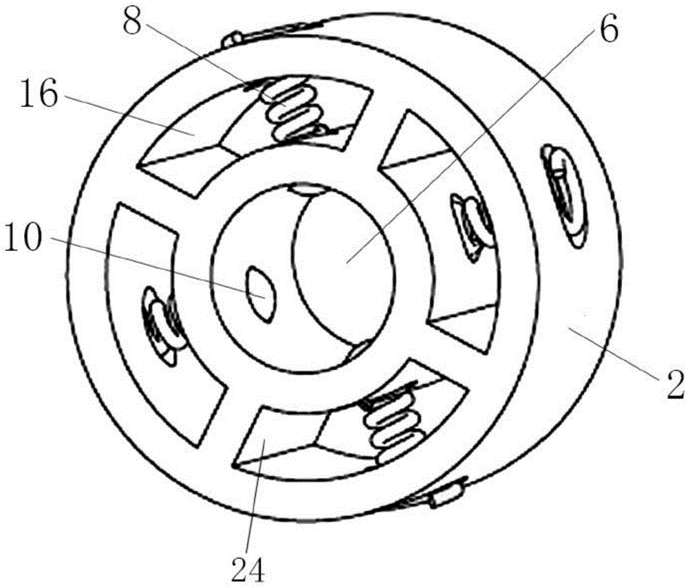
图2是本发明优选实施例中医用连接器的立体结构示意图;Figure 2 is a schematic three-dimensional structure diagram of a medical connector in a preferred embodiment of the present invention;
图3是图2中医用连接器的俯视结构示意图;Fig. 3 is the top-view structure schematic diagram of the medical connector in Fig. 2;
图4是图3中A-A方向的剖视结构示意图;Fig. 4 is the sectional structure schematic diagram of A-A direction in Fig. 3;
图5是图4中B部分的局部放大示意图;Fig. 5 is the partial enlarged schematic diagram of B part in Fig. 4;
图6是本发明第二实施例中弹性接触部的结构示意图;6 is a schematic structural diagram of an elastic contact portion in a second embodiment of the present invention;
图7是使用本发明优选实施例中的医用连接器将延伸导线连接至脉冲发生器上的结构示意图。FIG. 7 is a schematic structural diagram of using the medical connector in the preferred embodiment of the present invention to connect the extension lead to the pulse generator.
其中:1-连接块,3-螺钉;Among them: 1-connection block, 3-screw;
2-连接器本体,4-延伸导线,6-穿线通孔,8-弹性接触部,10-凸出抵接部,12-导电环,14-形变通道,16-容纳腔,18-孔口,20-脉冲发生器本体,22-连接器,24-连接臂。2-connector body, 4-extension wire, 6-through hole, 8-elastic contact part, 10-protruding abutment part, 12-conductive ring, 14-deformation channel, 16-accommodating cavity, 18-orifice , 20-pulse generator body, 22-connector, 24-connecting arm.
具体实施方式Detailed ways
下面结合附图和具体实施例对本发明作进一步说明,以使本领域的技术人员可以更好地理解本发明并能予以实施,但所举实施例不作为对本发明的限定。The present invention will be further described below with reference to the accompanying drawings and specific embodiments, so that those skilled in the art can better understand the present invention and implement it, but the embodiments are not intended to limit the present invention.
实施例一Example 1
如图1示出需要与脉冲发生器连接的延伸导线4的结构示意图,延伸导线4具有形成导电端子的导电环12。FIG. 1 shows a schematic structural diagram of the extension wire 4 to be connected with the pulse generator. The extension wire 4 has a
如图2-5所示,本实施例公开了一种连接医疗器械的医用连接器,用于将如图1所示的延伸导线4连接在脉冲发生器的连接头上,其包括连接器本体2,上述连接器本体2上设有供延伸导线4穿入的穿线通孔6,上述连接器本体2上设有弹性接触部8和形变通道14,上述形变通道14与穿线通孔6连通,上述弹性接触部8具有凸出抵接部10。As shown in Figures 2-5, this embodiment discloses a medical connector for connecting medical instruments, which is used to connect the extension wire 4 shown in Figure 1 to the connector of the pulse generator, which includes a
本实施例技术方案中,上述弹性接触部8的一端固定在连接器本体2上,凸出抵接部10固定在弹性接触部8的另一端,本实施例技术方案中,上述弹性接触部8优选但不局限于螺旋弹簧,螺旋弹簧的一端焊接固定在连接器本体2上,凸出抵接部10焊接固定在连接器本体2的另一端。In the technical solution of this embodiment, one end of the above-mentioned
此处需要说明的是:上述抵接部10可以是弹性接触部8的一部分,也可以是与弹性接触部8分离设置、且固定在弹性接触部8上。本实施例技术方案中优选方案为:抵接部10为与弹性接触部8分离设置的、优选但不局限于球状体结构,球状体结构的抵接部10固定在弹性接触部8上。It should be noted here that the
上述延伸导线4穿入穿线通孔6前:上述弹性接触部8处于自然状态或者被压缩,上述凸出抵接部10沿形变通道14伸入穿线通孔6内;Before the above-mentioned extension wire 4 penetrates into the threading through hole 6: the above-mentioned
上述延伸导线4穿入穿线通孔6后:上述延伸导线4挤压弹性接触部8,上述凸出抵接部10抵接延伸导线4的导电环12,上述凸出抵接部10自穿线通孔6向形变通道14方向回缩。凸出抵接部10回缩压缩或者再次压缩弹性接触部8,凸出抵接部10在弹性接触部8的反向挤压力作用下抵接压紧导电环12,与导电环12电气导通。After the extension wire 4 is inserted into the threading through hole 6: the extension wire 4 presses the
弹性接触部8弹性接触延伸导线4的导电环12,相较于传统的刚性接触,能够长期有效的保证凸出抵接部10与导电环之间的可靠电气导通连接。The
本实施例技术方案中,上述弹性接触部8具有环绕上述穿线通孔6一周设置的至少两个,如图2所示,具有但不限于四个结构相同的弹性接触部8,延伸导线4穿入穿线通孔6后,四个弹性接触部8的凸出抵接部10均环绕延伸导线4一圈的抵接压紧导电环12,与导电环12之间形成多点接触,形成多点导通,相较于单点接触的导通性能更稳定、可靠;与此同时,多点接触的设计能够降低对延伸导线的直线度要求,即使延伸导线的直线度不好,或者表面有凹坑,也能接触导通。尤其是,多个弹性接触部8以穿线通孔6的轴线为中心对称设置,也就是多个弹性接触部8以延伸导线4为中心对称设置的排布在其外围,多个凸出抵接部10对称分布能够均衡对延伸导线4的抵接力,凸出抵接部10能够更稳定的接触导电环12。In the technical solution of this embodiment, the above-mentioned
为了调整螺旋弹簧的弹力,根据实际的弹力需要,可以设计螺旋弹簧的螺距相同,或者沿某个方向逐渐减小或者逐渐增大。In order to adjust the elastic force of the coil spring, according to the actual elastic force requirements, the pitch of the coil spring can be designed to be the same, or gradually decrease or increase in a certain direction.
上述凸出抵接部10优选但不局限于使用金属制的球体结构,为了更紧密的贴合抵接导电环12,上述凸出抵接部10具有用于抵接导电环12的端部,上述端部具有匹配于导电环12外形结构的仿形结构。比如,在端部上开设仿形凹槽,接触导电环12时,仿形凹槽将导电环12环抱在内;或者,导电环12上设置线槽,端部上设置与线槽配合的仿形凸部,线槽将仿形凸部环抱在内。The above-mentioned
具体的,上述连接器本体2上位于穿线通孔6的外侧设有空腔,上述空腔内设有连接臂24,上述连接臂24将空腔分隔为多个容纳腔16,上述弹性接触部8设置在容纳腔16内,弹性接触部8的一端焊接在容纳腔16腔壁上,其另一端自由延伸,其自由延伸的端部焊接凸出抵接部10。当然,对应容纳多个弹性接触部8时,上述连接器本体2上环绕穿线通孔6一周设有多个容纳腔16,多个上述弹性接触部8一一对应的配置在上述容纳腔16内。Specifically, the
作为本发明的进一步改进,上述形变通道14内设有单向限位部,上述单向限位部对凸出抵接部10自形变通道14向穿线通孔6方向的移动进行限位,使得部分的上述凸出抵接部10伸入穿线通孔6内。单向限位部具有单向限位性:凸出抵接部10自形变通道14向穿线通孔6方向移动限位,而自穿线通孔6向形变通道14方向移动不做限位,确保延伸导线穿入穿线通孔6前只有部分的凸出抵接部10伸入穿线通孔6内,而凸出抵接部10在延伸导线4挤压力作用下能够没有限制的压缩弹性接触部8。以此可以避免凸出抵接部10全部伸入穿线通孔6内。一旦凸出抵接部10全部伸入穿线通孔6内,穿入延伸导线4后凸出抵接部10不能顺利的复位。As a further improvement of the present invention, the
本实施例技术方案中,单向限位部的优选但不局限的实现方案为:如图5所示,上述形变通道14与穿线通孔6连通处的通道口径小于凸出抵接部10的最大外径。In the technical solution of this embodiment, a preferred but not limited implementation solution of the one-way stopper is: as shown in FIG. Maximum outer diameter.
当然,根据实际使用需要,单向限位部还可以是其它的技术方案:形变通道14为内径相同的直线通道,设计弹性接触部8在自然状态时凸出抵接部10只有部分伸入穿线通孔6内,同样能够起到延伸导线4穿入穿线通孔后能够顺利复位的作用。Of course, according to the actual needs of use, the one-way limiting part can also be other technical solutions: the
为了约束弹性接触部8的形变轨迹,上述容纳腔16内导向套筒(未图示),上述导向套筒具有沿轴向贯穿的中心通孔,上述中心通孔的延伸方向与穿线通孔6的径向相同,上述弹性接触部8穿设在中心通孔内。借助导向套筒来约束弹性接触部8沿穿线通孔6径向往复直线移动。In order to constrain the deformation trajectory of the
实施例二
本实施例公开了一种连接医疗器械的医用连接器,本实施例中示出了弹性接触部8的另一种实现方式,如图6所示,上述弹性接触部8优选但不局限于弹板、弹片的结构,上述弹性接触部8的两端均固定在连接器本体2上,上述弹性接触部8的本体上具有上述凸出抵接部10。This embodiment discloses a medical connector for connecting medical instruments. Another implementation of the
当然,还可以设计弹性接触部8的一端固定在连接器本体2上,其另一端自由,弹性接触部8的本体上设置凸出抵接部10。Of course, one end of the
实施例三
如图7所示,公开了实施例一种用于植入式神经电刺激系统的脉冲发生器,包括脉冲发生器本体20、延伸导线4和以上结构的连接器22,上述延伸导线4的一端通过连接器22固定在脉冲发生器本体20上,其另一端连接电极。As shown in FIG. 7, an embodiment of a pulse generator for an implantable electrical nerve stimulation system is disclosed, including a
对应如图1所示的延伸导线4,使用四个以上结构的连接器22,分别对延伸导线4的四个导电环12进行连接导通,延伸导线4靠近设置导电环12的部位借助连接块1固定,连接块1上设有供延伸导线4穿入的通孔,连接块1上还设有连通孔的螺纹孔,螺纹孔内旋入螺钉,螺钉端部抵压延伸导线,对延伸导线进行限位固定,避免延伸导线沿轴向移动。Corresponding to the extension wire 4 shown in FIG. 1 , four or
使用实施例一或者实施例二中的连接器连接延伸导线4后,连接在脉冲发生器本体20上后,能够稳定可靠的将延伸导线4连接在脉冲发生器本体上,实现电极与脉冲发生器之间的良好导通性能,使用后能够降低对延伸导线的直线度要求。After using the connector in the first embodiment or the second embodiment to connect the extension wire 4, after connecting to the
以上所述实施例仅是为充分说明本发明而所举的较佳的实施例,本发明的保护范围不限于此。本技术领域的技术人员在本发明基础上所作的等同替代或变换,均在本发明的保护范围之内。本发明的保护范围以权利要求书为准。The above-mentioned embodiments are only preferred embodiments for fully illustrating the present invention, and the protection scope of the present invention is not limited thereto. Equivalent substitutions or transformations made by those skilled in the art on the basis of the present invention are all within the protection scope of the present invention. The protection scope of the present invention is subject to the claims.
Claims (10)
Priority Applications (1)
| Application Number | Priority Date | Filing Date | Title |
|---|---|---|---|
| CN201810803255.XA CN110732083A (en) | 2018-07-20 | 2018-07-20 | Medical connector and pulse generator for connecting medical instruments |
Applications Claiming Priority (1)
| Application Number | Priority Date | Filing Date | Title |
|---|---|---|---|
| CN201810803255.XA CN110732083A (en) | 2018-07-20 | 2018-07-20 | Medical connector and pulse generator for connecting medical instruments |
Publications (1)
| Publication Number | Publication Date |
|---|---|
| CN110732083A true CN110732083A (en) | 2020-01-31 |
Family
ID=69235621
Family Applications (1)
| Application Number | Title | Priority Date | Filing Date |
|---|---|---|---|
| CN201810803255.XA Pending CN110732083A (en) | 2018-07-20 | 2018-07-20 | Medical connector and pulse generator for connecting medical instruments |
Country Status (1)
| Country | Link |
|---|---|
| CN (1) | CN110732083A (en) |
Cited By (4)
| Publication number | Priority date | Publication date | Assignee | Title |
|---|---|---|---|---|
| CN111529936A (en) * | 2020-06-02 | 2020-08-14 | 苏州景昱医疗器械有限公司 | Nerve electrical stimulation system |
| CN112466137A (en) * | 2020-11-06 | 2021-03-09 | 杭州山治科技有限公司 | Energy-concerving and environment-protective sleet weather road traffic safety equipment of thing networked control |
| CN116581579A (en) * | 2023-07-14 | 2023-08-11 | 北京品驰医疗设备有限公司 | Medical connecting device, pulse generator and extension wire |
| US11978975B2 (en) | 2021-02-08 | 2024-05-07 | Heraeus Deutschland GmbH & Co. KG | Spring contact ring |
Citations (8)
| Publication number | Priority date | Publication date | Assignee | Title |
|---|---|---|---|---|
| US6112120A (en) * | 1997-07-03 | 2000-08-29 | Ela Medical S.A. | Apparatus for connecting a probe connector and an active implantable medical device |
| US20060004419A1 (en) * | 2004-04-05 | 2006-01-05 | Biotronik Gmbh & Co. Kg | Spring contact element |
| US20080248690A1 (en) * | 2007-04-06 | 2008-10-09 | Medtronic, Inc. | Connector and contact assemblies for medical devices |
| US20120089203A1 (en) * | 2010-10-12 | 2012-04-12 | Advanced Neuromodulation Systems, Inc. | Electrical connections for use in implantable medical devices |
| CN104075021A (en) * | 2014-07-11 | 2014-10-01 | 深圳市安博自控能源技术有限公司 | Valve anti-dismounting device and valve |
| CN106861045A (en) * | 2017-03-30 | 2017-06-20 | 苏州景昱医疗器械有限公司 | Extension wire and the Implanted medical system including the extension wire |
| CN107751119A (en) * | 2017-10-19 | 2018-03-06 | 西华大学 | The automatic bottom frame device of silkworm plaque |
| CN208823797U (en) * | 2018-07-20 | 2019-05-07 | 苏州景昱医疗器械有限公司 | Connect the medical connector and impulse generator of medical instrument |
-
2018
- 2018-07-20 CN CN201810803255.XA patent/CN110732083A/en active Pending
Patent Citations (8)
| Publication number | Priority date | Publication date | Assignee | Title |
|---|---|---|---|---|
| US6112120A (en) * | 1997-07-03 | 2000-08-29 | Ela Medical S.A. | Apparatus for connecting a probe connector and an active implantable medical device |
| US20060004419A1 (en) * | 2004-04-05 | 2006-01-05 | Biotronik Gmbh & Co. Kg | Spring contact element |
| US20080248690A1 (en) * | 2007-04-06 | 2008-10-09 | Medtronic, Inc. | Connector and contact assemblies for medical devices |
| US20120089203A1 (en) * | 2010-10-12 | 2012-04-12 | Advanced Neuromodulation Systems, Inc. | Electrical connections for use in implantable medical devices |
| CN104075021A (en) * | 2014-07-11 | 2014-10-01 | 深圳市安博自控能源技术有限公司 | Valve anti-dismounting device and valve |
| CN106861045A (en) * | 2017-03-30 | 2017-06-20 | 苏州景昱医疗器械有限公司 | Extension wire and the Implanted medical system including the extension wire |
| CN107751119A (en) * | 2017-10-19 | 2018-03-06 | 西华大学 | The automatic bottom frame device of silkworm plaque |
| CN208823797U (en) * | 2018-07-20 | 2019-05-07 | 苏州景昱医疗器械有限公司 | Connect the medical connector and impulse generator of medical instrument |
Cited By (6)
| Publication number | Priority date | Publication date | Assignee | Title |
|---|---|---|---|---|
| CN111529936A (en) * | 2020-06-02 | 2020-08-14 | 苏州景昱医疗器械有限公司 | Nerve electrical stimulation system |
| WO2021243952A1 (en) * | 2020-06-02 | 2021-12-09 | 苏州景昱医疗器械有限公司 | Nerve electrical stimulation system |
| CN112466137A (en) * | 2020-11-06 | 2021-03-09 | 杭州山治科技有限公司 | Energy-concerving and environment-protective sleet weather road traffic safety equipment of thing networked control |
| US11978975B2 (en) | 2021-02-08 | 2024-05-07 | Heraeus Deutschland GmbH & Co. KG | Spring contact ring |
| CN116581579A (en) * | 2023-07-14 | 2023-08-11 | 北京品驰医疗设备有限公司 | Medical connecting device, pulse generator and extension wire |
| CN116581579B (en) * | 2023-07-14 | 2023-10-31 | 北京品驰医疗设备有限公司 | Medical connecting device, pulse generator and extension wire |
Similar Documents
| Publication | Publication Date | Title |
|---|---|---|
| CN110732083A (en) | Medical connector and pulse generator for connecting medical instruments | |
| CN102361665B (en) | Implantable electrode with variable mechanical modulation wiring | |
| US7195523B2 (en) | Electrical conductive path for a medical electronics device | |
| US7583999B2 (en) | Multi-channel connector for brain stimulation system | |
| US20180289968A1 (en) | Tapered implantable lead and connector interface and methods of making and using | |
| US9095728B2 (en) | Electrical contact for implantable medical device | |
| CN112402786B (en) | An implantable vagus nerve stimulator electrode | |
| WO2018022455A1 (en) | Connector assembly with contact rings comprising biased ball-spring contacts | |
| CN105107091B (en) | Sealing-plug and the implantable medical device using the sealing-plug | |
| CN110801577B (en) | Nerve electrical stimulation system capable of configuring multiple implanted electrodes | |
| DE102011054296A1 (en) | Electrical connections for use in implantable medical devices | |
| EP0357941A2 (en) | Electrical connector between electrode leads and pacemaker terminal | |
| US20050165464A1 (en) | Implantable connector | |
| US10541500B2 (en) | Connector constructions and components thereof for implantable medical electrical systems | |
| US20070173914A1 (en) | Self-locking electrode assembly usable with an implantable medical device | |
| US7308312B1 (en) | Setscrew retention in connector block for implantable medical device | |
| US9112325B2 (en) | Contact configuration, contact assembly, implantable apparatus and electrode line | |
| US11103712B2 (en) | Connector assemblies with novel spacers for electrical stimulation systems and methods of making and using same | |
| CN204951951U (en) | Sealing plug and adopt implanted medical devices of this sealing plug | |
| CN220873915U (en) | Connectors, extension leads and implantable neurostimulation systems | |
| US7769459B2 (en) | Pigtail spring contacts for implanted medical devices | |
| US11497908B2 (en) | Screwless implantable medical lead extension | |
| CN208823797U (en) | Connect the medical connector and impulse generator of medical instrument | |
| EP4559512A1 (en) | Transmission module and electrical stimulation device | |
| CN204067727U (en) | A kind of cable connection structure with auto-lock function |
Legal Events
| Date | Code | Title | Description |
|---|---|---|---|
| PB01 | Publication | ||
| PB01 | Publication | ||
| SE01 | Entry into force of request for substantive examination | ||
| SE01 | Entry into force of request for substantive examination | ||
| CB02 | Change of applicant information | ||
| CB02 | Change of applicant information |
Address after: 215000 building C16, bio nano Park, 218 Xinghu street, Suzhou Industrial Park, Jiangsu Province Applicant after: Jingyu Medical Technology (Suzhou) Co.,Ltd. Address before: 215000 building C16, bio nano Park, 218 Xinghu street, Suzhou Industrial Park, Jiangsu Province Applicant before: SCENERAY Co.,Ltd. |
|
| RJ01 | Rejection of invention patent application after publication |
Application publication date: 20200131 |