CN110720062A - Optical bodies including multilayer optical films and thin adhesive layers - Google Patents
Optical bodies including multilayer optical films and thin adhesive layers Download PDFInfo
- Publication number
- CN110720062A CN110720062A CN201880036621.1A CN201880036621A CN110720062A CN 110720062 A CN110720062 A CN 110720062A CN 201880036621 A CN201880036621 A CN 201880036621A CN 110720062 A CN110720062 A CN 110720062A
- Authority
- CN
- China
- Prior art keywords
- adhesive layer
- optical
- multilayer optical
- optical film
- layer
- Prior art date
- Legal status (The legal status is an assumption and is not a legal conclusion. Google has not performed a legal analysis and makes no representation as to the accuracy of the status listed.)
- Pending
Links
Images


Classifications
-
- G—PHYSICS
- G02—OPTICS
- G02B—OPTICAL ELEMENTS, SYSTEMS OR APPARATUS
- G02B5/00—Optical elements other than lenses
- G02B5/30—Polarising elements
- G02B5/3025—Polarisers, i.e. arrangements capable of producing a definite output polarisation state from an unpolarised input state
- G02B5/3033—Polarisers, i.e. arrangements capable of producing a definite output polarisation state from an unpolarised input state in the form of a thin sheet or foil, e.g. Polaroid
- G02B5/3041—Polarisers, i.e. arrangements capable of producing a definite output polarisation state from an unpolarised input state in the form of a thin sheet or foil, e.g. Polaroid comprising multiple thin layers, e.g. multilayer stacks
- G02B5/305—Polarisers, i.e. arrangements capable of producing a definite output polarisation state from an unpolarised input state in the form of a thin sheet or foil, e.g. Polaroid comprising multiple thin layers, e.g. multilayer stacks including organic materials, e.g. polymeric layers
-
- B—PERFORMING OPERATIONS; TRANSPORTING
- B32—LAYERED PRODUCTS
- B32B—LAYERED PRODUCTS, i.e. PRODUCTS BUILT-UP OF STRATA OF FLAT OR NON-FLAT, e.g. CELLULAR OR HONEYCOMB, FORM
- B32B27/00—Layered products comprising a layer of synthetic resin
- B32B27/06—Layered products comprising a layer of synthetic resin as the main or only constituent of a layer, which is next to another layer of the same or of a different material
- B32B27/08—Layered products comprising a layer of synthetic resin as the main or only constituent of a layer, which is next to another layer of the same or of a different material of synthetic resin
-
- B—PERFORMING OPERATIONS; TRANSPORTING
- B32—LAYERED PRODUCTS
- B32B—LAYERED PRODUCTS, i.e. PRODUCTS BUILT-UP OF STRATA OF FLAT OR NON-FLAT, e.g. CELLULAR OR HONEYCOMB, FORM
- B32B7/00—Layered products characterised by the relation between layers; Layered products characterised by the relative orientation of features between layers, or by the relative values of a measurable parameter between layers, i.e. products comprising layers having different physical, chemical or physicochemical properties; Layered products characterised by the interconnection of layers
- B32B7/04—Interconnection of layers
- B32B7/06—Interconnection of layers permitting easy separation
-
- B—PERFORMING OPERATIONS; TRANSPORTING
- B32—LAYERED PRODUCTS
- B32B—LAYERED PRODUCTS, i.e. PRODUCTS BUILT-UP OF STRATA OF FLAT OR NON-FLAT, e.g. CELLULAR OR HONEYCOMB, FORM
- B32B7/00—Layered products characterised by the relation between layers; Layered products characterised by the relative orientation of features between layers, or by the relative values of a measurable parameter between layers, i.e. products comprising layers having different physical, chemical or physicochemical properties; Layered products characterised by the interconnection of layers
- B32B7/04—Interconnection of layers
- B32B7/12—Interconnection of layers using interposed adhesives or interposed materials with bonding properties
-
- C—CHEMISTRY; METALLURGY
- C09—DYES; PAINTS; POLISHES; NATURAL RESINS; ADHESIVES; COMPOSITIONS NOT OTHERWISE PROVIDED FOR; APPLICATIONS OF MATERIALS NOT OTHERWISE PROVIDED FOR
- C09J—ADHESIVES; NON-MECHANICAL ASPECTS OF ADHESIVE PROCESSES IN GENERAL; ADHESIVE PROCESSES NOT PROVIDED FOR ELSEWHERE; USE OF MATERIALS AS ADHESIVES
- C09J201/00—Adhesives based on unspecified macromolecular compounds
- C09J201/02—Adhesives based on unspecified macromolecular compounds characterised by the presence of specified groups, e.g. terminal or pendant functional groups
-
- C—CHEMISTRY; METALLURGY
- C09—DYES; PAINTS; POLISHES; NATURAL RESINS; ADHESIVES; COMPOSITIONS NOT OTHERWISE PROVIDED FOR; APPLICATIONS OF MATERIALS NOT OTHERWISE PROVIDED FOR
- C09J—ADHESIVES; NON-MECHANICAL ASPECTS OF ADHESIVE PROCESSES IN GENERAL; ADHESIVE PROCESSES NOT PROVIDED FOR ELSEWHERE; USE OF MATERIALS AS ADHESIVES
- C09J7/00—Adhesives in the form of films or foils
- C09J7/20—Adhesives in the form of films or foils characterised by their carriers
- C09J7/29—Laminated material
-
- B—PERFORMING OPERATIONS; TRANSPORTING
- B32—LAYERED PRODUCTS
- B32B—LAYERED PRODUCTS, i.e. PRODUCTS BUILT-UP OF STRATA OF FLAT OR NON-FLAT, e.g. CELLULAR OR HONEYCOMB, FORM
- B32B37/00—Methods or apparatus for laminating, e.g. by curing or by ultrasonic bonding
- B32B37/12—Methods or apparatus for laminating, e.g. by curing or by ultrasonic bonding characterised by using adhesives
- B32B2037/1253—Methods or apparatus for laminating, e.g. by curing or by ultrasonic bonding characterised by using adhesives curable adhesive
-
- B—PERFORMING OPERATIONS; TRANSPORTING
- B32—LAYERED PRODUCTS
- B32B—LAYERED PRODUCTS, i.e. PRODUCTS BUILT-UP OF STRATA OF FLAT OR NON-FLAT, e.g. CELLULAR OR HONEYCOMB, FORM
- B32B2307/00—Properties of the layers or laminate
- B32B2307/40—Properties of the layers or laminate having particular optical properties
- B32B2307/42—Polarizing, birefringent, filtering
-
- B—PERFORMING OPERATIONS; TRANSPORTING
- B32—LAYERED PRODUCTS
- B32B—LAYERED PRODUCTS, i.e. PRODUCTS BUILT-UP OF STRATA OF FLAT OR NON-FLAT, e.g. CELLULAR OR HONEYCOMB, FORM
- B32B2307/00—Properties of the layers or laminate
- B32B2307/50—Properties of the layers or laminate having particular mechanical properties
- B32B2307/538—Roughness
-
- B—PERFORMING OPERATIONS; TRANSPORTING
- B32—LAYERED PRODUCTS
- B32B—LAYERED PRODUCTS, i.e. PRODUCTS BUILT-UP OF STRATA OF FLAT OR NON-FLAT, e.g. CELLULAR OR HONEYCOMB, FORM
- B32B2457/00—Electrical equipment
- B32B2457/20—Displays, e.g. liquid crystal displays, plasma displays
-
- B—PERFORMING OPERATIONS; TRANSPORTING
- B32—LAYERED PRODUCTS
- B32B—LAYERED PRODUCTS, i.e. PRODUCTS BUILT-UP OF STRATA OF FLAT OR NON-FLAT, e.g. CELLULAR OR HONEYCOMB, FORM
- B32B2457/00—Electrical equipment
- B32B2457/20—Displays, e.g. liquid crystal displays, plasma displays
- B32B2457/202—LCD, i.e. liquid crystal displays
-
- C—CHEMISTRY; METALLURGY
- C09—DYES; PAINTS; POLISHES; NATURAL RESINS; ADHESIVES; COMPOSITIONS NOT OTHERWISE PROVIDED FOR; APPLICATIONS OF MATERIALS NOT OTHERWISE PROVIDED FOR
- C09J—ADHESIVES; NON-MECHANICAL ASPECTS OF ADHESIVE PROCESSES IN GENERAL; ADHESIVE PROCESSES NOT PROVIDED FOR ELSEWHERE; USE OF MATERIALS AS ADHESIVES
- C09J133/00—Adhesives based on homopolymers or copolymers of compounds having one or more unsaturated aliphatic radicals, each having only one carbon-to-carbon double bond, and at least one being terminated by only one carboxyl radical, or of salts, anhydrides, esters, amides, imides, or nitriles thereof; Adhesives based on derivatives of such polymers
- C09J133/04—Homopolymers or copolymers of esters
- C09J133/06—Homopolymers or copolymers of esters of esters containing only carbon, hydrogen and oxygen, the oxygen atom being present only as part of the carboxyl radical
- C09J133/08—Homopolymers or copolymers of acrylic acid esters
-
- C—CHEMISTRY; METALLURGY
- C09—DYES; PAINTS; POLISHES; NATURAL RESINS; ADHESIVES; COMPOSITIONS NOT OTHERWISE PROVIDED FOR; APPLICATIONS OF MATERIALS NOT OTHERWISE PROVIDED FOR
- C09J—ADHESIVES; NON-MECHANICAL ASPECTS OF ADHESIVE PROCESSES IN GENERAL; ADHESIVE PROCESSES NOT PROVIDED FOR ELSEWHERE; USE OF MATERIALS AS ADHESIVES
- C09J2203/00—Applications of adhesives in processes or use of adhesives in the form of films or foils
- C09J2203/318—Applications of adhesives in processes or use of adhesives in the form of films or foils for the production of liquid crystal displays
-
- C—CHEMISTRY; METALLURGY
- C09—DYES; PAINTS; POLISHES; NATURAL RESINS; ADHESIVES; COMPOSITIONS NOT OTHERWISE PROVIDED FOR; APPLICATIONS OF MATERIALS NOT OTHERWISE PROVIDED FOR
- C09J—ADHESIVES; NON-MECHANICAL ASPECTS OF ADHESIVE PROCESSES IN GENERAL; ADHESIVE PROCESSES NOT PROVIDED FOR ELSEWHERE; USE OF MATERIALS AS ADHESIVES
- C09J2301/00—Additional features of adhesives in the form of films or foils
- C09J2301/30—Additional features of adhesives in the form of films or foils characterized by the chemical, physicochemical or physical properties of the adhesive or the carrier
- C09J2301/302—Additional features of adhesives in the form of films or foils characterized by the chemical, physicochemical or physical properties of the adhesive or the carrier the adhesive being pressure-sensitive, i.e. tacky at temperatures inferior to 30°C
-
- C—CHEMISTRY; METALLURGY
- C09—DYES; PAINTS; POLISHES; NATURAL RESINS; ADHESIVES; COMPOSITIONS NOT OTHERWISE PROVIDED FOR; APPLICATIONS OF MATERIALS NOT OTHERWISE PROVIDED FOR
- C09J—ADHESIVES; NON-MECHANICAL ASPECTS OF ADHESIVE PROCESSES IN GENERAL; ADHESIVE PROCESSES NOT PROVIDED FOR ELSEWHERE; USE OF MATERIALS AS ADHESIVES
- C09J2433/00—Presence of (meth)acrylic polymer
-
- C—CHEMISTRY; METALLURGY
- C09—DYES; PAINTS; POLISHES; NATURAL RESINS; ADHESIVES; COMPOSITIONS NOT OTHERWISE PROVIDED FOR; APPLICATIONS OF MATERIALS NOT OTHERWISE PROVIDED FOR
- C09K—MATERIALS FOR MISCELLANEOUS APPLICATIONS, NOT PROVIDED FOR ELSEWHERE
- C09K2323/00—Functional layers of liquid crystal optical display excluding electroactive liquid crystal layer characterised by chemical composition
- C09K2323/03—Viewing layer characterised by chemical composition
- C09K2323/031—Polarizer or dye
-
- C—CHEMISTRY; METALLURGY
- C09—DYES; PAINTS; POLISHES; NATURAL RESINS; ADHESIVES; COMPOSITIONS NOT OTHERWISE PROVIDED FOR; APPLICATIONS OF MATERIALS NOT OTHERWISE PROVIDED FOR
- C09K—MATERIALS FOR MISCELLANEOUS APPLICATIONS, NOT PROVIDED FOR ELSEWHERE
- C09K2323/00—Functional layers of liquid crystal optical display excluding electroactive liquid crystal layer characterised by chemical composition
- C09K2323/05—Bonding or intermediate layer characterised by chemical composition, e.g. sealant or spacer
- C09K2323/057—Ester polymer, e.g. polycarbonate, polyacrylate or polyester
-
- C—CHEMISTRY; METALLURGY
- C09—DYES; PAINTS; POLISHES; NATURAL RESINS; ADHESIVES; COMPOSITIONS NOT OTHERWISE PROVIDED FOR; APPLICATIONS OF MATERIALS NOT OTHERWISE PROVIDED FOR
- C09K—MATERIALS FOR MISCELLANEOUS APPLICATIONS, NOT PROVIDED FOR ELSEWHERE
- C09K2323/00—Functional layers of liquid crystal optical display excluding electroactive liquid crystal layer characterised by chemical composition
- C09K2323/06—Substrate layer characterised by chemical composition
- C09K2323/061—Inorganic, e.g. ceramic, metallic or glass
Landscapes
- Physics & Mathematics (AREA)
- Chemical & Material Sciences (AREA)
- Organic Chemistry (AREA)
- General Physics & Mathematics (AREA)
- Optics & Photonics (AREA)
- Laminated Bodies (AREA)
- Polarising Elements (AREA)
- Surface Treatment Of Optical Elements (AREA)
- Optical Elements Other Than Lenses (AREA)
Abstract
本发明描述了光学主体。具体地,描述了具有双折射多层光学膜和连续的粘合剂层的光学主体,该连续的粘合剂层具有小于20微米的厚度。本文所述的光学主体表现出被称为“橘皮”的不均匀缺陷的降低的发生率和严重程度。

This invention describes an optical body. Specifically, it describes an optical body having a birefringent multilayer optical film and a continuous adhesive layer having a thickness of less than 20 micrometers. The optical body described herein exhibits a reduced incidence and severity of non-uniform defects known as "orange peel."
Description
背景技术Background technique
光学主体包括至少一个光学膜或其它光学部件。多层光学膜可用作反射器或反射偏振器,并且常常包括共拉伸的交替层,该共拉伸的交替层包含双折射聚合物。粘合剂使某些部件能够粘附到包括膜、光学部件和基底的其它部件。The optical body includes at least one optical film or other optical component. Multilayer optical films can be used as reflectors or reflective polarizers, and often include co-stretched alternating layers comprising birefringent polymers. Adhesives enable certain components to adhere to other components including films, optical components, and substrates.
发明内容SUMMARY OF THE INVENTION
在一个方面,本说明书涉及光学主体。具体地,本说明书涉及光学主体,该光学主体包括:双折射多层光学膜;连续的粘合剂层,该连续的粘合剂层设置在双折射多层光学膜的第一主表面上;以及聚合物衬垫,该聚合物衬垫设置在连续的粘合剂层上。连续的粘合剂层具有小于20微米的厚度,并且包含这样的粘合剂,该粘合剂来源于粘度介于10cps和50,000cps之间的溶液。In one aspect, the present specification relates to optical bodies. In particular, the present specification relates to an optical body comprising: a birefringent multilayer optical film; a continuous adhesive layer disposed on a first major surface of the birefringent multilayer optical film; and a polymer liner disposed on the continuous adhesive layer. The continuous adhesive layer has a thickness of less than 20 microns and comprises an adhesive derived from a solution having a viscosity between 10 cps and 50,000 cps.
在另一方面,本说明书涉及光学主体。具体地,本说明书涉及光学主体,该光学主体包括:双折射多层光学膜;连续的粘合剂层,该连续的粘合剂层设置在双折射多层光学膜的第一主表面上;和玻璃或塑料基底层,该玻璃或塑料基底层经由连续的粘合剂层附接到多层光学膜。利用干涉仪透过玻璃或塑料基底层测量,该光学主体具有小于40nm的Ra表面粗糙度。In another aspect, the present specification relates to optical bodies. In particular, the present specification relates to an optical body comprising: a birefringent multilayer optical film; a continuous adhesive layer disposed on a first major surface of the birefringent multilayer optical film; and a glass or plastic substrate layer attached to the multilayer optical film via a continuous adhesive layer. The optical body has an Ra surface roughness of less than 40 nm as measured through an interferometer through a glass or plastic substrate.
在另一方面,本说明书涉及提供光学上平滑的层合光学主体的方法。具体地,本说明书涉及通过以下方式提供光学上平滑的层合光学主体:提供双折射多层光学膜,该双折射多层光学膜涂覆有连续的粘合剂层,该连续的粘合剂层具有小于20微米的厚度,并且将聚合物衬垫设置在连续的粘合剂层上;移除聚合物衬垫;以及将双折射多层光学膜和连续的粘合剂层附接到玻璃或塑料基底层以形成光学上平滑的层合光学主体。利用干涉仪透过玻璃或塑料基底层测量,该光学上平滑的层合光学主体具有小于40nm的Ra表面粗糙度。In another aspect, the present specification relates to a method of providing an optically smooth laminated optical body. In particular, the present specification relates to providing an optically smooth laminated optical body by providing a birefringent multilayer optical film coated with a continuous adhesive layer, the continuous adhesive layer having a thickness of less than 20 microns and disposing a polymer liner on the continuous adhesive layer; removing the polymer liner; and attaching the birefringent multilayer optical film and the continuous adhesive layer to the glass or a plastic base layer to form an optically smooth laminated optical body. The optically smooth laminated optical body has an Ra surface roughness of less than 40 nm as measured by an interferometer through a glass or plastic base layer.
附图说明Description of drawings
图1为光学主体的示意性正视图。Figure 1 is a schematic front view of an optical body.
图2为另一个光学主体的示意性正视图。Figure 2 is a schematic front view of another optical body.
图3为示出了某些光学主体的表面粗糙度的测量的示意图。FIG. 3 is a schematic diagram illustrating the measurement of surface roughness of certain optical bodies.
图4为将实施例1和比较例3的光学平滑度进行比较的箱形图。4 is a box plot comparing the optical smoothness of Example 1 and Comparative Example 3. FIG.
具体实施方式Detailed ways
光学主体可用于许多应用中。例如,包括刚性基底层诸如玻璃或塑料的光学主体可用于投影系统(例如,作为偏振分束器或在抬头显示系统中)、虚拟现实系统或其中基底的刚度或环境稳定性可有益于应用的其它应用。Optical bodies can be used in many applications. For example, optical bodies comprising rigid substrate layers such as glass or plastic may be used in projection systems (eg, as polarizing beam splitters or in heads-up display systems), virtual reality systems, or where the stiffness or environmental stability of the substrate may benefit applications other applications.
遗憾的是,以前难以在不引入可被描述为“橘皮”的不均匀缺陷的情况下将光学主体层合到基底层。可以通过透过层合光学主体的反射或透射来观察到橘皮。对于敏感的光学应用,此类橘皮不均匀性可在此类光学主体所属的光学系统中产生不期望的光学伪影。例如,光学主体中的橘皮可使反射离开此类光学主体的投影图像呈现波浪形或不均匀。此外,即使非常好地遵从常规幅材和卷材处理的最佳实践,在消除或甚至大幅减少橘皮方面也不太有效。Unfortunately, it has previously been difficult to laminate optical bodies to substrate layers without introducing a non-uniform defect that can be described as "orange peel." Orange peel can be observed by reflection or transmission through the laminated optical body. For sensitive optical applications, such orange peel inhomogeneities can produce undesirable optical artifacts in the optical system to which such optical bodies belong. For example, orange peel in optical bodies can make projected images reflected off such optical bodies appear wavy or uneven. Furthermore, even very good adherence to conventional web and coil handling best practices is not very effective in eliminating or even substantially reducing orange peel.
本文所述的光学主体包括当层合到基底层时令人惊奇地减少橘皮的特征。不同于小心处理,这些特征是光学主体构造中的物理差异,其导致成品层合构造中更平滑的层合和减少的橘皮。The optical bodies described herein include features that surprisingly reduce orange peel when laminated to a base layer. Unlike careful handling, these features are physical differences in the optical body construction that result in smoother lamination and reduced orange peel in the finished laminated construction.
图1为光学主体的示意性正视图。光学主体100包括双折射多层光学膜110、连续的粘合剂层120、聚合物衬垫130和硬质涂膜层140。Figure 1 is a schematic front view of an optical body.
双折射多层光学膜110包括至少两种不同材料的交替微层。多层光学膜,即至少部分地通过具有不同折射率的微层的布置提供期望的透射和/或反射特性的膜是已知的。众所周知,此类多层光学膜通过在真空室中将一系列无机材料以光学薄层(“微层”)的形式沉积于基底上而制备。无机多层光学膜描述在教科书中,例如H.A.Macleod,薄膜光学滤波器,第二版,麦克米伦出版公司(1986年)(H.A.Macleod,Thin-Film Optical Filters,2ndEd.,Macmillan Publishing Co.(1986))和A.Thelan,光学干涉滤波器的设计,麦格劳希尔公司(1989年)(A.Thelan,Design of Optical Interference Filters,McGraw-Hill,Inc.(1989))。The birefringent multilayer
也已通过共挤出交替的聚合物层展示多层光学膜。参见例如美国专利3,610,729(Rogers)、4,446,305(Rogers等人)、4,540,623(Im等人)、5,448,404(Schrenk等人)以及5,882,774(Jonza等人)。在这些种聚合物多层光学膜中,聚合物材料主要或专门用于各个层的制备中。此类膜适合高产量制造工艺,并且可制成大型片材和卷材。Multilayer optical films have also been demonstrated by coextruding alternating polymer layers. See, eg, US Patents 3,610,729 (Rogers), 4,446,305 (Rogers et al), 4,540,623 (Im et al), 5,448,404 (Schrenk et al), and 5,882,774 (Jonza et al). In these kinds of polymeric multilayer optical films, the polymeric material is used primarily or exclusively in the preparation of the individual layers. These films are suitable for high-volume manufacturing processes and can be made into large sheets and rolls.
多层光学膜包括具有不同折射率特征的各个微层,使得一些光在相邻微层之间的界面处被反射。微层是足够薄的,使得在多个界面处反射的光经受相长干涉或相消干涉作用,以便赋予多层光学膜期望的反射或透射特性。对于被设计成反射紫外光、可见光或近红外波长光的多层光学膜而言,每个微层通常具有小于约1μm的光学厚度(物理厚度乘以折射率)。通常可以将层布置为最薄至最厚的。在一些实施方案中,交替光学层的布置可根据层计数而基本上线性地变化。这些层曲线可以被称为线性层曲线。可以包括更厚的层,诸如在多层光学膜的外表面处的表层或者设置在多层光学膜内用以将微层的相干组(本文中被称为“分组”)分开的保护性边界层(PBL)。在一些实施方案中,双折射多层光学膜110可包括至少两个分组。在一些实施方案中,双折射多层光学膜的这两个分组具有重叠至少80%的厚度。在一些情况下,保护性边界层可以是与多层光学膜的交替层中的至少一个相同的材料。在其它情况下,保护性边界层可以是根据其物理特性或流变学特性而选择的不同材料。保护性边界层可以位于光分组的一侧或两侧上。在单分组多层光学膜的情况下,保护性边界层可以位于多层光学膜的一个或两个外表面上。Multilayer optical films include individual microlayers with different refractive index characteristics such that some light is reflected at interfaces between adjacent microlayers. The microlayers are thin enough that light reflected at multiple interfaces experiences constructive or destructive interference in order to impart desired reflective or transmissive properties to the multilayer optical film. For multilayer optical films designed to reflect light at ultraviolet, visible, or near-infrared wavelengths, each microlayer typically has an optical thickness (physical thickness times refractive index) of less than about 1 μm. The layers can generally be arranged from the thinnest to the thickest. In some embodiments, the arrangement of alternating optical layers may vary substantially linearly according to the layer count. These layer curves may be referred to as linear layer curves. Thicker layers may be included, such as skin layers at the outer surface of the multilayer optical film or protective boundaries disposed within the multilayer optical film to separate coherent groups of microlayers (referred to herein as "groups") layer (PBL). In some embodiments, the birefringent multilayer
有时添加表层,其在进料区块之后但在熔融物离开膜模头之前发生。然后,以用于聚酯膜的传统方式将多层熔融物通过膜模头浇铸到冷却辊上,在该冷却辊上对其进行淬火。然后,浇铸料片以不同方式拉伸,以获得在光学层中的至少一个中的双折射,从而产生在许多情况下为反射偏振器或镜膜,如已经描述于例如美国专利公布2007/047080A1、美国专利公布2011/0102891A1、以及美国专利7,104,776(Merrill等人)中。具有双折射性的膜可被称为双折射多层光学膜。A skin layer is sometimes added, which occurs after the feed block but before the melt exits the film die. The multilayer melt was then cast through a film die onto chill rolls where it was quenched in the conventional manner for polyester films. The casting web is then stretched in various ways to achieve birefringence in at least one of the optical layers, resulting in in many cases a reflective polarizer or mirror film, as has been described, for example, in US Patent Publication 2007/047080A1 , US Patent Publication 2011/0102891 A1, and US Patent 7,104,776 (Merrill et al.). Films having birefringence may be referred to as birefringent multilayer optical films.
双折射多层光学膜110可具有任何合适的反射特征。例如,双折射多层光学膜110可以是反射偏振器,其优先反射一种偏振的光,同时优先透射第二正交偏振的光。在一些实施方案中,双折射多层光学膜可包括四分之一波延迟器或附接到四分之一波延迟器,以有效地形成圆形反射偏振器。在一些实施方案中,对于550nm的光,四分之一波延迟器可具有137.5nm的50nm内的延迟。在一些实施方案中,四分之一波延迟器可以是或包括双折射拉伸聚合物膜。在一些实施方案中,四分之一波延迟器可以是或包括液晶层。在一些实施方案中,四分之一波延迟器可以在扩展的波长范围内是消色差的;也就是说,四分之一波延迟器可以在该扩展的波长范围内提供大约四分之一波延迟。在一些实施方案中,双折射多层光学膜110可以是反射每种正交偏振的光的反射镜。在一些实施方案中,双折射多层光学膜110反射40%的法向入射非偏振光、反射50%的法向入射非偏振光、反射60%的法向入射非偏振光、反射70%的法向入射非偏振光、反射80%的法向入射非偏振光、反射90%的法向入射非偏振光、或甚至反射超过95%的法向入射非偏振光。The birefringent multilayer
在一些实施方案中,双折射多层光学膜是厚的。在一些实施方案中,双折射多层光学膜比35微米厚。在一些实施方案中,双折射多层光学膜比50微米厚。在一些实施方案中,双折射多层光学膜比60微米厚。双折射多层光学膜可以是任何合适的形状或尺寸,这取决于应用。通常,层合产品中的双折射多层光学膜为基本上矩形的,从卷膜转换。在一些情况下,双折射多层光学膜的厚度可改善橘皮的外观和发生率。In some embodiments, the birefringent multilayer optical film is thick. In some embodiments, the birefringent multilayer optical film is thicker than 35 microns. In some embodiments, the birefringent multilayer optical film is thicker than 50 microns. In some embodiments, the birefringent multilayer optical film is thicker than 60 microns. The birefringent multilayer optical film can be of any suitable shape or size, depending on the application. Typically, birefringent multilayer optical films in laminated products are substantially rectangular, converted from roll films. In some cases, the thickness of the birefringent multilayer optical film can improve the appearance and incidence of orange peel.
在一些实施方案中,双折射多层光学膜包括吸收元件。在一些实施方案中,这些吸收元件为吸收偏振元件。在一些实施方案中,这些吸收元件为宽带吸收器,其吸收两种正交偏振的光。在一些实施方案中,吸收偏振元件可仅设置在双折射多层光学膜的高折射率层内。包括吸收元件的示例性偏振器描述于美国专利公布2016-0306086(Haag等人)和美国专利6,096,375(Ouderkirk等人)中。In some embodiments, the birefringent multilayer optical film includes absorbing elements. In some embodiments, the absorbing elements are absorbing polarizing elements. In some embodiments, the absorbing elements are broadband absorbers that absorb light of two orthogonal polarizations. In some embodiments, the absorptive polarizing element may be disposed only within the high index layer of the birefringent multilayer optical film. Exemplary polarizers including absorbing elements are described in US Patent Publication 2016-0306086 (Haag et al.) and US Patent 6,096,375 (Ouderkirk et al.).
连续的粘合剂层120设置在双折射多层光学膜110的第一主表面上。连续的粘合剂层可包含任何合适的粘合剂或粘合剂的组合。在一些实施方案中,连续的粘合剂层120包含光学透明的粘合剂。在一些实施方案中,连续的粘合剂层120包含基于丙烯酸类或丙烯酸酯的粘合剂。在一些实施方案中,连续的粘合剂层120包含基于聚氨酯、聚烯烃、聚酯或有机硅的光学透明的粘合剂。在一些实施方案中,连续的粘合剂层120包含可涂覆粘合剂。可涂覆粘合剂可具有介于10cps和50,000cps之间的涂层粘度。此类可涂覆粘合剂允许粘合剂以比常规使用的低得多的厚度(例如,使用成品粘合剂层与光学膜的干层合)容易地施加,这对橘皮的减少具有令人惊奇地强烈的影响。然而,粘合剂应当以允许施加连续层的厚度涂覆或以其它方式施加。在一些实施方案中,连续的粘合剂层具有小于20微米的厚度。在一些实施方案中,连续的粘合剂层具有小于15微米的厚度。在一些实施方案中,连续的粘合剂层具有小于10微米的厚度。在一些实施方案中,连续的粘合剂层具有小于5微米的厚度。在某些应用中,本文所述的光学主体经受极端环境条件。例如,某些光学主体可用于汽车应用中,其中部件可能必须在温度达120℃时不会失效。在这些应用中,可能期望选择交联粘合剂以防止渗漏、蠕变或其它由于高温造成的失效。A
粘合剂层可以是完全固化的(即交联的)粘合剂,或者其可以在层合到基底层之前部分交联或甚至不交联。在施加后,粘合剂层可随后交联,诸如通过简单的辐射处理(UV、电子束、γ)、热暴露(例如,使用热活化交联剂)、暴露于水分(例如,如果使用硅烷官能化交联剂)以及它们的组合。The adhesive layer may be a fully cured (ie, cross-linked) adhesive, or it may be partially cross-linked or even not cross-linked prior to lamination to the base layer. After application, the adhesive layer can be subsequently crosslinked, such as by simple radiation treatment (UV, e-beam, gamma), thermal exposure (eg, using a thermally activated crosslinker), exposure to moisture (eg, if silanes are used) functionalized crosslinkers) and combinations thereof.
聚合物衬垫130可为任何合适的厚度和组成。聚合物衬垫130通常被暂时附接到连续的粘合剂层120的与双折射多层光学膜110相对的另一侧,以便在储存、运输和转换期间保护粘合剂层。在一些实施方案中,聚合物衬垫130可为模糊的或甚至包含颜料,以便容易地识别具有粘合剂的侧。在一些实施方案中,聚合物衬垫可为热定型的或预收缩的,以便防止在环境循环期间(包括在储存和运输期间)翘曲或卷曲。在一些实施方案中,聚合物衬垫130可具有低表面能或包括低表面能处理以便能够容易地移除。用于聚合物衬垫130的合适的膜可包含取向聚对苯二甲酸乙二醇酯。在一些实施方案中,光学上平滑的聚合物衬垫可用于在加工期间保持光学平滑度。
硬质涂膜层140设置在双折射多层光学膜上,与连续的粘合剂层和聚合物衬垫相对,并且可以是具有任何合适厚度和硬度的任何合适的硬质涂膜层。硬质涂膜层和涂层在膜处理层中是熟知的,并且可基于期望的应用、工艺条件和其它特征来选择合适的硬质涂膜材料。在一些实施方案中,与双折射多层光学膜组合测量的硬质涂膜层140可仅具有2H或更硬的铅笔硬度。在一些实施方案中,硬质涂膜层140可具有HB或更硬的铅笔硬度。在一些实施方案中,硬质涂膜层令人惊奇地改善了最终层合光学主体上的橘皮的发生率和严重程度。在一些实施方案中,硬质涂膜层可包含一种或多种紫外线吸收剂。在一些实施方案中,一个或多个任选的保护性膜层可设置在硬质涂膜层(未示出)上。此类保护性膜可为聚合物层,其包含聚酯诸如聚对苯二甲酸乙二醇酯。The
图2为另一个光学主体的示意性正视图。光学主体200包括双折射多层光学膜210、连续的粘合剂层220、硬质涂膜层240和基底层250。图2中的光学主体200可以基本上对应于图1中的光学主体100,不同的是聚合物衬垫被移除并且光学主体100的其余部分已附接或层合到基底层250。Figure 2 is a schematic front view of another optical body.
基底层250可以是任何合适的基底。在许多应用中,基底层250是或包括塑料或玻璃。可使用任何合适的塑料诸如聚碳酸酯或丙烯酸类,或任何合适的玻璃诸如碱石灰玻璃或硼硅酸盐玻璃。在一些实施方案中,选择基底层250以实现光学特性,诸如透明度(例如,大于90%的光透射率和小于5%的雾度)。在一些实施方案中,选择基底层250以实现物理特性,诸如抗翘曲性、不透湿性、刚度、抗破损性等。基底层250的厚度取决于具体应用,但在某些情况下可在几毫米至几厘米厚的范围内。
图3为示出了某些光学主体的表面粗糙度的测量的示意图。光学主体300的表面粗糙度由干涉仪360测量。干涉仪诸如ZYGO NEWVIEW 8000(购自康涅狄格州米德尔菲尔德的Zygo公司(Zygo Corporation,Middlefield,Conn.))能够测量表面粗糙度,该表面粗糙度被认为是相当好地对应于橘皮的主观感知的客观测量。干涉仪360和光学主体300被构造成使得干涉仪360透过基底层测量光学主体300的表面粗糙度。FIG. 3 is a schematic diagram illustrating the measurement of surface roughness of certain optical bodies. The surface roughness of the
根据本文的描述制备的光学主体可以具有小于40nm、小于30nm、小于20nm、或甚至小于10nm的表面粗糙度(Ra)。也可使用表面粗糙度的替代测量,例如峰-谷或均方根。可接受的峰-谷表面粗糙度值可小于250nm、小于200nm、小于100nm、或甚至小于50nm。可接受的均方根表面粗糙度值可小于50nm、小于40nm、小于20nm、或甚至小于10nm。Optical bodies prepared according to the descriptions herein can have a surface roughness (Ra) of less than 40 nm, less than 30 nm, less than 20 nm, or even less than 10 nm. Alternative measures of surface roughness may also be used, such as peak-to-valley or root mean square. Acceptable peak-to-valley surface roughness values may be less than 250 nm, less than 200 nm, less than 100 nm, or even less than 50 nm. Acceptable rms surface roughness values may be less than 50 nm, less than 40 nm, less than 20 nm, or even less than 10 nm.
在一些实施方案中,如本文所述的光学主体可在某些投影系统中使用。在一些实施方案中,如本文所述的光学主体可在反射镜显示系统中使用,其中光学主体将设置在发射或液晶显示面板的正面(朝向观察者)上。In some embodiments, optical bodies as described herein may be used in certain projection systems. In some embodiments, an optical body as described herein may be used in a mirror display system, where the optical body would be disposed on the front side (facing the viewer) of an emissive or liquid crystal display panel.
除非另外指明,否则针对附图中元件的描述应被理解为同样应用于其它附图中的对应元件。本发明不应被视为限于上述具体实施例和实施方案,因为详细描述此类实施方案是为了便于说明本发明的各个方面。相反,本发明应被理解为涵盖本发明的所有方面,包括落在由所附权利要求书及其等同物所限定的本发明的范围内的各种修改、等同工艺和替代装置。Unless otherwise indicated, descriptions of elements in a figure should be understood to apply equally to corresponding elements in other figures. The present invention should not be construed as limited to the specific examples and embodiments described above, since such embodiments are described in detail for ease of illustrating various aspects of the invention. On the contrary, the invention should be understood to cover all aspects of the invention including various modifications, equivalent processes and alternative arrangements falling within the scope of the invention as defined by the appended claims and their equivalents.
实施例Example
以下实施例将常规形成的双折射反射偏振器(CE-1)与镜面反射偏振器(实施例1)进行比较。这些实施例进一步将常规集成的吸收反射偏振器(CE-2)与镜面吸收反射偏振器进行比较。每个实施例的光学平滑度、环境稳定性和光学特性的测试结果如下。The following examples compare a conventionally formed birefringent reflective polarizer (CE-1) to a specularly reflective polarizer (Example 1). These examples further compare a conventional integrated absorbing reflective polarizer (CE-2) with a specular absorbing reflective polarizer. The test results of optical smoothness, environmental stability and optical properties of each example are as follows.
材料/来源Materials/Sources
RF02N是购自中国深圳市的SKC Haas公司(SKC Haas(Shenzhen City,China))的剥离衬垫RF02N is a release liner available from SKC Haas (Shenzhen City, China)
RF32N是购自中国深圳市的SKC Haas公司(SKC Haas(Shenzhen City,China))的剥离衬垫RF32N is a release liner available from SKC Haas (Shenzhen City, China)
APF-V4和APF-T35是购自明尼苏达州圣保罗的3M公司(3M Company,St.Paul,Minn)的反射偏振膜。APF-V4 and APF-T35 are reflective polarizing films available from 3M Company, St. Paul, Minn.
比较例(CE-1)Comparative Example (CE-1)
如下制备具有常规表面的双折射反射偏振器。如美国专利6,088,159的实施例中所述,共挤出三个多层光学膜分组。将两种聚合物用于光学层。第一聚合物(第一光学层)是具有121摄氏度至123摄氏度的Tg的聚萘二甲酸乙二醇酯(PEN)均聚物(100摩尔%的萘二甲酸酯与100摩尔%的乙二醇)。第二聚合物(第二光学层)是第一聚萘二甲酸乙二醇酯共聚物(coPEN),其具有55摩尔%的萘酸酯和45摩尔%的对苯二甲酸酯作为羧酸酯,以及95.8摩尔%的乙二醇、4摩尔%的己二醇和0.2摩尔%的三羟甲基丙烷作为二醇,其具有94摄氏度的Tg。用于表层的聚合物是第二coPEN,其具有75摩尔%的萘酸酯和25摩尔%的对苯二甲酸酯作为羧酸酯,以及95.8摩尔%的乙二醇、4摩尔%的己二醇和0.2摩尔%的三羟甲基丙烷作为二醇,其具有101摄氏度的Tg。这些聚酯可例如按照美国专利6,352,761(Hebrink等人)中所述形成。Birefringent reflective polarizers with conventional surfaces were prepared as follows. Three multi-layer optical film subgroups were coextruded as described in the examples of US Patent 6,088,159. Two polymers were used for the optical layer. The first polymer (first optical layer) was a polyethylene naphthalate (PEN) homopolymer (100 mole % naphthalate with 100 mole % ethyl acetate) having a Tg of 121 to 123 degrees Celsius. glycol). The second polymer (second optical layer) is a first polyethylene naphthalate copolymer (coPEN) with 55 mole % naphthalate and 45 mole % terephthalate as carboxylic acid ester, and 95.8 mol% ethylene glycol, 4 mol% hexanediol, and 0.2 mol% trimethylolpropane as diols, which have a Tg of 94 degrees Celsius. The polymer used for the skin layer was a second coPEN with 75 mol% naphthalate and 25 mol% terephthalate as carboxylates, and 95.8 mol% ethylene glycol, 4 mol% hexane. Diol and 0.2 mol% trimethylolpropane as diol, which has a Tg of 101 degrees Celsius. These polyesters can be formed, for example, as described in US Pat. No. 6,352,761 (Hebrink et al.).
将PEN和第一coPEN聚合物从单独的挤出机中进料到多层共挤出进料区块,在该进料区块中,它们被组装成具有275个交替光学层的分组,加上每一侧各有一个较厚的coPEN保护性边界层,总共277个层。多层熔融物从进料区块被运送通过一个三折层倍增器,从而生成具有829个层的构造。第二coPEN表层被添加到特定于该用途的歧管构造,从而生成具有831个层的最终构造。然后,以用于聚酯膜的传统方式将多层熔融物通过膜模头浇铸到冷却辊上,在该冷却辊上对其进行淬火。然后将浇铸料片在工业规模的线性拉幅机中在类似于美国专利公布2007-0047080(Stover等人)的实施例2中所述的温度和拉延分布下拉伸。The PEN and first coPEN polymers were fed from separate extruders to a multilayer coextrusion feedblock where they were assembled into groups of 275 alternating optical layers, plus There is a thicker protective boundary layer of coPEN on each side, for a total of 277 layers. The multilayer melt was conveyed from the feed block through a three-fold layer multiplier, resulting in a construction with 829 layers. A second coPEN skin layer was added to the manifold construction specific to this application, resulting in a final construction with 831 layers. The multilayer melt was then cast through a film die onto chill rolls where it was quenched in the conventional manner for polyester films. The cast webs were then stretched in a commercial scale linear tenter frame at temperatures and draw profiles similar to those described in Example 2 of US Patent Publication 2007-0047080 (Stover et al.).
在制备该多层膜之后,该膜具有如通过电容式测厚仪测量的大约92μm的所得物理厚度,如使用Ono-Sokki DG-925千分尺(日本横滨(Yokohama,Japan))测量的那样。After preparing the multilayer film, the film had a resulting physical thickness of approximately 92 μm as measured by a capacitance thickness gauge, as measured using an Ono-Sokki DG-925 micrometer (Yokohama, Japan).
在拉伸之后,第一分组仅具有反射偏振器功能。在制备该膜的过程中,使用以商品名“ULTRAMASK 1035”由弗吉尼亚州里士满的卓德嘉公司(Tredegar(Richmond,Va.))生产的标准聚乙烯型预掩模层合到反射偏振片的表面,以用于保护膜并将其卷绕成巨型卷的目的。After stretching, the first packet has only reflective polarizer functionality. In making the film, a standard polyethylene-type pre-mask manufactured by Tredegar (Richmond, Va.) under the trade designation "ULTRAMASK 1035" was used to laminate to a reflective polarizer The surface of the sheet for the purpose of protecting the film and winding it into jumbo rolls.
实施例1Example 1
反射偏振器镜膜如下进行制备。如美国专利公布2011-0102891(Derks等人)中所述共挤出两个多层光分组,不同之处如下。第一分组和第二分组的第一光学层由具有121摄氏度至123摄氏度的Tg的聚萘二甲酸乙二醇酯(PEN)均聚物(100摩尔%的萘二甲酸酯与100摩尔%的乙二醇)的共混物构成。第一分组和第二分组的第二光学聚合物层是聚碳酸酯和共聚酯的共混物(PC:coPET),使得折射率为约1.57并且在单轴取向时保持基本上各向同性,其中PC:coPET摩尔比为大约42.5摩尔%的PC和57.5摩尔%的coPET,并且具有105摄氏度的Tg。用于表层的聚合物由第二光学层中使用的相同材料构成。Reflective polarizer mirror films were prepared as follows. Two multilayer optical packets were coextruded as described in US Patent Publication 2011-0102891 (Derks et al.) with the following differences. The first optical layers of the first and second subgroups are composed of a polyethylene naphthalate (PEN) homopolymer (100 mole % naphthalate with 100 mole % Tg of 121 degrees Celsius to 123 degrees Celsius) of ethylene glycol). The second optical polymer layers of the first and second subgroups are a blend of polycarbonate and copolyester (PC:coPET) such that the refractive index is about 1.57 and remains substantially isotropic when uniaxially oriented , where the PC:coPET molar ratio is approximately 42.5 mol % PC and 57.5 mol % coPET, and has a Tg of 105 degrees Celsius. The polymer used for the skin layer consists of the same material used in the second optical layer.
将材料从单独的挤出机进料到多层共挤出进料区块,在该进料区块中,材料被组装成具有325个交替光学层的第一分组和同样具有325个交替层的第二分组。表层被添加到特定于该用途的歧管构造,从而生成具有656个层的最终构造。然后,以用于聚酯膜的传统方式将多层熔融物通过膜模头浇铸到冷却辊上,在该冷却辊上对其进行淬火。然后将浇铸料片在工业规模的线性拉幅机中在类似于美国专利公布2007-0047080(Stover等人)的实施例2中所述的温度和拉延分布下拉伸。由电容式测厚仪测量的该膜的物理厚度为大约63μm,如使用Ono-Sokki DG-925千分尺测量的那样。The material was fed from a separate extruder to a multi-layer coextrusion feedblock where the material was assembled into a first subgroup with 325 alternating optical layers and also 325 alternating layers of the second group. Skin layers were added to the manifold build specific to the application, resulting in a final build with 656 layers. The multilayer melt was then cast through a film die onto chill rolls where it was quenched in the conventional manner for polyester films. The cast webs were then stretched in a commercial scale linear tenter frame at temperatures and draw profiles similar to those described in Example 2 of US Patent Publication 2007-0047080 (Stover et al.). The physical thickness of the film as measured by a capacitive thickness gauge was approximately 63 μm, as measured using an Ono-Sokki DG-925 micrometer.
在制备反射偏振器镜膜的过程中,将以商品名NSA33T购自日本东京的三樱化研公司(Sun A.Kaken(Tokyo,Japan))的光学上平滑的预掩模施加到集成偏振片的表面,以用于保护膜并保持膜的光学上平滑特征的目的,如在图4中测量和显示的。During the preparation of the reflective polarizer mirror film, an optically smooth pre-mask available from Sun A. Kaken (Tokyo, Japan) under the trade designation NSA33T was applied to the integrated polarizer , for the purpose of protecting the film and maintaining the optically smooth characteristics of the film, as measured and shown in Figure 4.
将CE-1或实施例1卷绕成卷形式后,将它们与涂覆有标记为OCA-2的3M OCA粘合剂层合。该OCA-2材料是根据美国专利公布2006-0246296(Xia等人)的实施例1、使用10份添加剂I和90份PSA 1(固体)制备的,不同之处在于代替0.1份双酰胺/100份干粘合剂,使用0.15份双酰胺。经由清洁的溶剂涂覆线施加OCA-2和剥离衬垫(RF02N,购自中国深圳的SKC Haas公司(SKC Haas,Shenzhen,China))。这在集成偏振器上提供了粘合剂层,以使其能够用于各种应用。After CE-1 or Example 1 were wound into roll form, they were laminated with a 3M OCA adhesive coated with the designation OCA-2. The OCA-2 material was prepared according to Example 1 of US Patent Publication 2006-0246296 (Xia et al.) using 10 parts Additive 1 and 90 parts PSA 1 (solids), except instead of 0.1 part bisamide/100 parts dry adhesive, use 0.15 part bisamide. OCA-2 and release liner (RF02N, available from SKC Haas, Shenzhen, China) were applied via a clean solvent-coated line. This provides an adhesive layer on the integrated polarizer to enable it to be used in a variety of applications.
为了完成该层合,使用挤出涂覆法首先将OCA-2涂覆在RF02N剥离衬垫上,使其(干)厚度为2μm至30μm。随后将所得粘合剂涂层在介于110℃和160℃之间的范围内的烘箱温度下干燥,直到大部分溶剂已从该涂层中去除。然后用粘合剂将膜(CE-1或实施例1)层合到剥离衬垫上。To complete the lamination, OCA-2 was first coated on an RF02N release liner using extrusion coating to a (dry) thickness of 2 μm to 30 μm. The resulting adhesive coating was then dried at oven temperatures ranging between 110°C and 160°C until most of the solvent had been removed from the coating. The film (CE-1 or Example 1) was then laminated to a release liner with an adhesive.
比较例2(CE-2)Comparative Example 2 (CE-2)
通过常规方法如下制备集成的吸收反射偏振器。如美国专利公布2011-0102891(Derks等人)中所述共挤出单个多层光分组,不同之处如下。第一光学层由具有121摄氏度至123摄氏度的Tg的聚萘二甲酸乙二醇酯(PEN)均聚物(100摩尔%的萘二甲酸酯与100摩尔%的乙二醇)和四种不同的二色性可共挤出吸收染料(购自日本东京日本三井精细化工公司(Mitsui Fine Chemical,(Japan,Tokyo,Japan))的PD-325H、PD-335H、PD-104和PD-318H)的共混物构成,如美国专利公布2015-0378077(Haag等人)中所述。实施例1中使用的染料重量百分比如下:PD-325H=1.67重量%,PD-335H=0.21重量%,PD-104=0.67重量%,并且PD-318H=1.25重量%。第二聚合物(第二光学层)是共混物,其由PEN和PETG的共混物制备,使得折射率为约1.60并且在单轴取向时保持基本上各向同性,其中重量比为大约45重量%的LmPEN和55重量%的PETG,并且具有100摄氏度的Tg。用于“空气”侧表层的聚合物由90/10coPEN的共混物构成,即由90%的聚萘二甲酸乙二醇酯(PEN)和10%的聚对苯二甲酸乙二醇酯(PET)构成的聚合物。用于“轮”侧表皮的聚合物由具有121摄氏度至123摄氏度的Tg的聚萘二甲酸乙二醇酯(PEN)均聚物(100摩尔%的萘二甲酸酯与100摩尔%的乙二醇)和四种不同的二色性可共挤出吸收染料(购自日本东京日本三井精细化工公司(Mitsui Fine Chemical,(Japan,Tokyo,Japan))的PD-325H、PD-335H、PD-104和PD-318H)的共混物构成,如美国专利公布2015-0378077(Haag等人)中所述。实施例1中用于轮侧表皮的染料重量百分比如下:PD-325H=0.93重量%,PD-335H=0.35重量%%,PD-104=0.56重量%,并且PD-318H=0.41重量%。Integrated absorptive reflective polarizers were prepared by conventional methods as follows. A single multilayer optical packet was coextruded as described in US Patent Publication 2011-0102891 (Derks et al.) with the following differences. The first optical layer is composed of a polyethylene naphthalate (PEN) homopolymer (100 mole % naphthalate and 100 mole % ethylene glycol) having a Tg of 121 to 123 degrees Celsius and four Different dichroic coextrudable absorbing dyes (PD-325H, PD-335H, PD-104 and PD-318H purchased from Mitsui Fine Chemical, (Japan, Tokyo, Japan)) ), as described in US Patent Publication 2015-0378077 (Haag et al.). The dye weight percentages used in Example 1 were as follows: PD-325H = 1.67 wt %, PD-335H = 0.21 wt %, PD-104 = 0.67 wt %, and PD-318H = 1.25 wt %. The second polymer (second optical layer) is a blend prepared from a blend of PEN and PETG such that the refractive index is about 1.60 and remains substantially isotropic when uniaxially oriented, with a weight ratio of about 45 wt% LmPEN and 55 wt% PETG with a Tg of 100 degrees Celsius. The polymer used for the "air" side skin consisted of a 90/10 coPEN blend of 90% polyethylene naphthalate (PEN) and 10% polyethylene terephthalate ( PET) polymers. The polymer used for the "wheel" side skin consisted of a polyethylene naphthalate (PEN) homopolymer (100 mole % naphthalate with 100 mole % ethyl acetate) with a Tg of 121 to 123 degrees Celsius. PD-325H, PD-335H, PD, PD-325H, PD-335H, PD -104 and PD-318H) blend compositions as described in US Patent Publication 2015-0378077 (Haag et al.). The dye weight percentages used for the wheel side skin in Example 1 were as follows: PD-325H = 0.93 wt %, PD-335H = 0.35 wt %, PD-104 = 0.56 wt %, and PD-318H = 0.41 wt %.
将材料从单独的挤出机进料到多层共挤出进料区块,在该进料区块中,材料被组装成具有305个交替的光学层的分组。第一光学层材料的表层被添加到特定于该用途的歧管构造,从而生成具有307个层的最终构造。然后,以用于聚酯膜的传统方式将多层熔融物通过膜模头浇铸到冷却辊上,在该冷却辊上对其进行淬火。然后将浇铸料片在工业规模的线性拉幅机中在类似于美国专利公布2007-0047080A1(Stover等人)的实施例2中所述的温度和拉延分布下拉伸。由电容式测厚仪测量的该膜的物理厚度为大约65μm,如使用Ono-Sokki DG-925千分尺测量的那样。The material was fed from a separate extruder to a multilayer coextrusion feedblock where the material was assembled into groups of 305 alternating optical layers. A skin layer of the first optical layer material was added to the manifold construction specific to the application, resulting in a final construction with 307 layers. The multilayer melt was then cast through a film die onto chill rolls where it was quenched in the conventional manner for polyester films. The cast webs were then stretched in a commercial scale linear tenter frame at temperatures and draw profiles similar to those described in Example 2 of US Patent Publication 2007-0047080A1 (Stover et al.). The physical thickness of the film as measured by a capacitive thickness gauge was approximately 65 μm, as measured using an Ono-Sokki DG-925 micrometer.
实施例2Example 2
如下制备具有镜面光洁度的集成吸收反射偏振器示例。如美国专利公布2011-0102891(Derks等人)中所述共挤出两个多层光分组,不同之处如下。第一分组的第一光学层由具有121摄氏度至123摄氏度的Tg的聚萘二甲酸乙二醇酯(PEN)均聚物(100摩尔%的萘二甲酸酯与100摩尔%的乙二醇)和四种不同的二色性可共挤出吸收染料(购自日本东京日本三井精细化工公司(Mitsui Fine Chemical,(Japan,Tokyo,Japan))的PD-325H、PD-335H、PD-104和PD-318H)的共混物构成,如美国专利公布2015-0378077(Haag等人)中所述。实施例1中使用的染料重量百分比如下:PD-325H=1.67重量%,PD-335H=0.21重量%,PD-104=0.67重量%,并且PD-318H=1.25重量%。第一分组的第二光学聚合物层是共混物,其由聚碳酸酯和共聚酯的共混物(PC:coPET)制备,使得折射率为约1.57并且在单轴取向时保持基本上各向同性,其中PC:coPET摩尔比为大约42.5摩尔%的PC和57.5摩尔%的coPET,并且具有105摄氏度的Tg。用于“空气”侧表层的聚合物由90/10coPEN的共混物构成,即由90%的聚萘二甲酸乙二醇酯(PEN)和10%的聚对苯二甲酸乙二醇酯(PET)构成的聚合物。用于“轮”侧表皮(或膜流延侧)的聚合物由具有121摄氏度至123摄氏度的Tg的聚萘二甲酸乙二醇酯(PEN)均聚物(100摩尔%的萘二甲酸酯与100摩尔%的乙二醇)和四种不同的二色性可共挤出吸收染料(购自日本东京日本三井精细化工公司(Mitsui Fine Chemical,(Japan,Tokyo,Japan))的PD-325H、PD-335H、PD-104和PD-318H)的共混物构成,如美国专利公布2015-0378077(Haag等人)中所述。实施例2中用于膜流延侧表皮的染料重量百分比如下:PD-325H=0.93重量%,PD-335H=0.35重量%%,PD-104=0.56重量%,并且PD-318H=0.41重量%。An example of an integrated absorptive reflective polarizer with a specular finish was prepared as follows. Two multilayer optical packets were coextruded as described in US Patent Publication 2011-0102891 (Derks et al.) with the following differences. The first optical layer of the first subgroup is composed of a polyethylene naphthalate (PEN) homopolymer (100 mole % naphthalate with 100 mole % ethylene glycol) having a Tg of 121 degrees Celsius to 123 degrees Celsius ) and four different dichroic co-extrudable absorbing dyes (PD-325H, PD-335H, PD-104 purchased from Mitsui Fine Chemical, (Japan, Tokyo, Japan)) and PD-318H), as described in US Patent Publication 2015-0378077 (Haag et al.). The dye weight percentages used in Example 1 were as follows: PD-325H = 1.67 wt %, PD-335H = 0.21 wt %, PD-104 = 0.67 wt %, and PD-318H = 1.25 wt %. The second optical polymer layer of the first group is a blend prepared from a blend of polycarbonate and copolyester (PC:coPET) such that the refractive index is about 1.57 and remains substantially uniaxially oriented Isotropic with a PC:coPET molar ratio of approximately 42.5 mol % PC and 57.5 mol % coPET with a Tg of 105 degrees Celsius. The polymer used for the "air" side skin consisted of a 90/10 coPEN blend of 90% polyethylene naphthalate (PEN) and 10% polyethylene terephthalate ( PET) polymers. The polymer used for the "wheel" side skin (or film casting side) consisted of a polyethylene naphthalate (PEN) homopolymer (100 mole % naphthalene dicarboxylic acid) with a Tg of 121 to 123 degrees Celsius ester with 100 mol % ethylene glycol) and four different dichroic co-extrudable absorbing dyes (PD-P-A, purchased from Mitsui Fine Chemical, (Japan, Tokyo, Japan)) 325H, PD-335H, PD-104, and PD-318H) blend compositions as described in US Patent Publication 2015-0378077 (Haag et al.). The dye weight percentages used for the film casting side skin in Example 2 were as follows: PD-325H = 0.93 wt %, PD-335H = 0.35 wt %, PD-104 = 0.56 wt %, and PD-318H = 0.41 wt % .
第二分组的第一光学层由具有121摄氏度至123摄氏度的Tg的聚萘二甲酸乙二醇酯(PEN)均聚物(100摩尔%的萘二甲酸酯与100摩尔%的乙二醇)的共混物构成。第二分组的第二光学聚合物层是共混物,其由聚碳酸酯和共聚酯的共混物(PC:coPET)制备,使得折射率为约1.57并且在单轴取向时保持基本上各向同性,其中PC:coPET摩尔比为大约42.5摩尔%的PC和57.5摩尔%的coPET,并且具有105摄氏度的Tg。用于“空气”侧表层的聚合物由90/10coPEN的共混物构成,即由90%的聚萘二甲酸乙二醇酯(PEN)和10%的聚对苯二甲酸乙二醇酯(PET)构成的聚合物。用于空气侧表皮的聚合物由具有121摄氏度至123摄氏度的Tg的聚萘二甲酸乙二醇酯(PEN)均聚物(100摩尔%的萘二甲酸酯与100摩尔%的乙二醇)的共混物构成。The first optical layer of the second grouping is composed of a polyethylene naphthalate (PEN) homopolymer (100 mole % naphthalate with 100 mole % ethylene glycol) having a Tg of 121 to 123 degrees Celsius ) blends. The second optical polymer layer of the second subgroup is a blend prepared from a blend of polycarbonate and copolyester (PC:coPET) such that the refractive index is about 1.57 and remains substantially uniaxially oriented Isotropic with a PC:coPET molar ratio of approximately 42.5 mol % PC and 57.5 mol % coPET with a Tg of 105 degrees Celsius. The polymer used for the "air" side skin consisted of a 90/10 coPEN blend of 90% polyethylene naphthalate (PEN) and 10% polyethylene terephthalate ( PET) polymers. The polymer used for the airside skin consists of a polyethylene naphthalate (PEN) homopolymer (100 mole % naphthalate with 100 mole % ethylene glycol) having a Tg of 121 to 123 degrees Celsius ) blends.
将材料从单独的挤出机进料到多层共挤出进料区块,在该进料区块中,材料被组装成具有305个交替光学层的第一分组和同样具有305个交替层的第二分组。第一光学层材料的表层被添加到特定于该用途的歧管构造,从而生成具有307个层的最终构造。然后,以用于聚酯膜的传统方式将多层熔融物通过膜模头浇铸到冷却辊上,在该冷却辊上对其进行淬火。然后将浇铸料片在工业规模的线性拉幅机中在类似于美国专利公布2007-0047080A1(Stover等人)的实施例2中所述的温度和拉延分布下拉伸。由电容式测厚仪测量的该膜的物理厚度为大约65μm。在拉伸之后,第一分组具有吸收偏振器功能,而第二光分组具有反射偏振器功能。在制备集成偏振器的过程中,将以商品名NSA33T购自日本东京的三樱化研公司(Sun A.Kaken(Tokyo,Japan))的光学上平滑的预掩模施加到集成偏振片的表面,以用于保护膜并保持膜的光学上平滑特征的目的,如在图4中测量和显示的。The material was fed from a separate extruder to a multi-layer coextrusion feedblock where the material was assembled into a first subgroup with 305 alternating optical layers and also 305 alternating layers of the second group. A skin layer of the first optical layer material was added to the manifold construction specific to the application, resulting in a final construction with 307 layers. The multilayer melt was then cast through a film die onto chill rolls where it was quenched in the conventional manner for polyester films. The cast webs were then stretched in a commercial scale linear tenter frame at temperatures and draw profiles similar to those described in Example 2 of US Patent Publication 2007-0047080A1 (Stover et al.). The physical thickness of the film as measured by a capacitive thickness gauge was approximately 65 μm. After stretching, the first subgroup has an absorbing polarizer function, while the second optical subgroup has a reflective polarizer function. During the preparation of the integrated polarizer, an optically smooth pre-mask commercially available from Sun A. Kaken (Tokyo, Japan) under the tradename NSA33T was applied to the surface of the integrated polarizer , for the purpose of protecting the film and maintaining the optically smooth characteristics of the film, as measured and shown in FIG. 4 .
比较例3(CE-3)Comparative Example 3 (CE-3)
购买Sanitz 5618H型偏振器(日本东京(Tokyo,Japan))作为该例中的偏振器,使用产品随附的粘合剂。相对于具有表1和表2中提供的结果数据的实施例,该材料可作为环境性能的比较例。A Sanitz 5618H type polarizer (Tokyo, Japan) was purchased as the polarizer in this example, using the adhesive provided with the product. This material serves as a comparative example of environmental performance relative to the Examples with the resulting data provided in Tables 1 and 2.
测试结果Test Results
光学平滑度测试Optical Smoothness Test
本文所述构造的一个优点是提供在视觉上镜面样的表面,其没有被称为橘皮的细微缺陷。这种感知的视觉缺陷可由专家观察者主观地排序,但也趋于与表面特征粗糙度的可测量参数良好相关。使用Zygo干涉仪型号NV5000-5032(购自康涅狄格州米德尔菲尔德Zygo公司(Zygo Corporation,Middlefield,Conn.))测量了光学表面特征One advantage of the constructions described herein is to provide a visually mirror-like surface that is free of the subtle imperfections known as orange peel. Such perceived visual defects can be subjectively ranked by expert observers, but also tend to correlate well with measurable parameters of surface feature roughness. Optical surface features were measured using a Zygo interferometer model NV5000-5032 (available from Zygo Corporation, Middlefield, Conn.)
为了进行这些测量,首先将实施例膜层合到玻璃板。记录了CE-1和实施例1的Zygo干涉仪报告的峰-谷(PV)、RMS和Ra[微米]的值,其中结果在图4中进行了比较。实施例1演示了35nm的峰-谷粗糙度,其小于可见光谱中光波长的1/10,而测得比较例(CE-1)的粗糙度为260nm至320nm。To make these measurements, the example films were first laminated to a glass plate. The peak-to-valley (PV), RMS and Ra [microns] values reported for the Zygo interferometers of CE-1 and Example 1 were recorded, with the results compared in FIG. 4 . Example 1 demonstrates a peak-to-valley roughness of 35 nm, which is less than 1/10 the wavelength of light in the visible spectrum, while the roughness of Comparative Example (CE-1 ) was measured to be 260 nm to 320 nm.
有效透光率测试Effective transmittance test
测量所制备的光学组件中的每一个的有效透光率。提供壁厚为约0.6cm并且边长为约11cm的聚四氟乙烯立方体。经由高强度光纤灯管从其内部照亮该立方体。立方体的高度扩散的半透明壁提供了具有高度均匀(朗伯曲线)亮度的参考表面。相对于外立方体面居中并且沿立方体面的法线定位的亮度计,记录了在亮度计与立方体面之间提供有和没有样品中的每一个的情况下立方体面上的亮度。包括样品与不包括样品的亮度的比率为有效透光率。然后,将有效透光率“增益”计算为样品测量值与基线测量值的比率。在间隔一段时间的环境暴露之后重新采集增益测量值,以跟踪有效透光率增益的变化,并将该增益比率的变化作为“Δ增益”列入表格,其中Δ增益=(暴露之后的增益)/(初始增益)。The effective light transmittance of each of the prepared optical assemblies was measured. Teflon cubes with a wall thickness of about 0.6 cm and sides of about 11 cm were provided. The cube is illuminated from its interior via a high-intensity fiber optic light tube. The highly diffuse translucent walls of the cube provide a reference surface with highly uniform (Lambertian) brightness. The luminance on the cube face was recorded with and without each of the samples provided between the luminance meter and the cube face with a luminance meter centered relative to the outer cube face and positioned along the normal to the cube face. The ratio of brightness including sample to excluding sample is the effective light transmittance. The effective transmittance "gain" is then calculated as the ratio of the sample measurement to the baseline measurement. Gain measurements were re-acquired after an interval of environmental exposure to track the change in effective transmittance gain and tabulated this gain ratio change as "delta gain", where delta gain = (gain after exposure) /(Initial gain).
颜色变化测试(ΔE)Color Change Test (ΔE)
对颜色变化的测量使用Minolta CM3500d相机(美能达有限公司(Minolta Co,Ltd.))来测量在具有和不具有多层光学膜样品情况下的透射光的颜色(L*,a*,b*)。用于测量的光源是用于颜色测量的工业标准D65/10光源,并且然后基于K7103和K7105中详述的日本工业标准来计算颜色变化(ΔE)。ΔE的结果列于表1至3中。Measurement of Color Change A Minolta CM3500d camera (Minolta Co, Ltd.) was used to measure the color of transmitted light (L*, a*, b* with and without multilayer optical film samples) ). The light source used for the measurement was the industry standard D65/10 light source for color measurement, and the color change (ΔE) was then calculated based on the Japanese Industrial Standard detailed in K7103 and K7105. The results of ΔE are listed in Tables 1-3.
环境暴露测试Environmental Exposure Testing
与常规可用产品相比,这些光学上平滑的反射和集成偏振片制品在需要保持偏振和使用温度的工业市场中具有适用性。为此,进行了环境暴露测试。These optically smooth reflective and integrated polarizer articles have applicability in industrial markets where polarization and service temperature maintenance is required compared to conventionally available products. For this, environmental exposure tests were carried out.
表1示出了将实施例1与比较例3在高温和高湿度老化(在85℃/85%相对湿度下250小时)方面进行比较的数据。表2示出了将实施例1和比较例3在非常高的温度(120℃下250小时)方面进行比较的数据。在这两项比较中,实施例1的构造具有在环境暴露下优异的光学特性保持。在这些结果中,利用多种光学透明的粘合剂并且然后将构造物层合到玻璃,使实施例1经受老化环境。所用的粘合剂包括3M 8146,它是购自明尼苏达州圣保罗的3M公司(3M Company,St.Paul,Minn.)的可商购获得的光学透明的粘合剂(OCA)。第二种OCA粘合剂标记为OCA-2,如先前实施例1中所述那样制备。重复样表示相同样品构型的多个复制品。因此,例如,利用8146/A层合的实施例1在利用8146/B层合的实施例1中复制。所得样品依次由玻璃、光学透明的粘合剂和多层光学膜构成。因此,每个样品具有“玻璃侧”和“膜侧”,如下表所示。Table 1 shows data comparing Example 1 with Comparative Example 3 for high temperature and high humidity aging (250 hours at 85°C/85% relative humidity). Table 2 shows data comparing Example 1 and Comparative Example 3 at very high temperatures (250 hours at 120°C). In both comparisons, the construction of Example 1 had excellent retention of optical properties under ambient exposure. In these results, Example 1 was subjected to an aging environment using various optically clear adhesives and then laminating the construct to glass. Adhesives used included 3M 8146, a commercially available optically clear adhesive (OCA) from 3M Company, St. Paul, Minn., from 3M Company, St. Paul, Minn.. The second OCA adhesive, designated OCA-2, was prepared as previously described in Example 1. Replicates represent multiple replicates of the same sample configuration. Thus, for example, Example 1 laminated with 8146/A is replicated in Example 1 laminated with 8146/B. The resulting samples consisted of glass, an optically clear adhesive, and a multilayer optical film, in that order. Therefore, each sample has a "glass side" and a "film side" as shown in the table below.

表1:Δ增益=(暴露之后的增益/暴露之前的增益),ΔT=Δ透光率(%),ΔH=Δ 雾度(%),并且ΔE=在85℃/85%RH下250小时的颜色变化。 Table 1: ΔGain=(Gain after exposure/Gain before exposure), ΔT=ΔTransmittance (%), ΔH=ΔHaze (%), and ΔE=250 hours at 85°C/85%RH color change .

表2:Δ增益=(暴露之后的增益/暴露之前的增益),ΔT=Δ透光率(%),ΔH=ΔTable 2: ΔGain=(Gain after exposure/Gain before exposure), ΔT=ΔTransmittance (%), ΔH=Δ 雾度(%),并且ΔE=在120℃下250小时的颜色变化。Haze (%), and ΔE = color change at 120°C for 250 hours.
与比较例2相比,实施例1和实施例2还进行了更长时间段的老化,并且结果列于表3中。结果示出了光学上平滑的表面带来的改善的热稳健性,实现了具有改善的光反射率的偏振片。Examples 1 and 2 were also aged for longer periods of time than Comparative Example 2, and the results are presented in Table 3. The results show improved thermal robustness with optically smooth surfaces, enabling polarizers with improved light reflectivity.
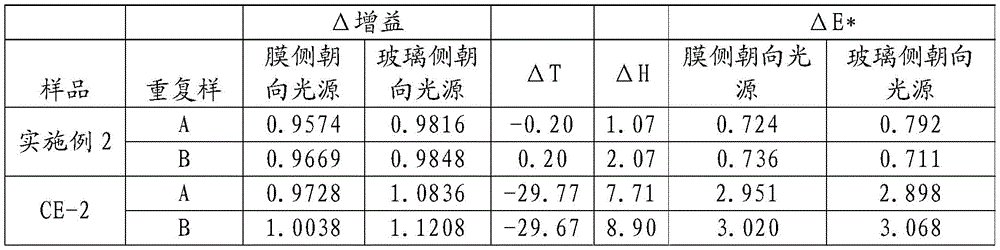

表3Δ增益=(暴露之后的增益/暴露之前的增益),ΔT=Δ透光率(%),ΔH=Δ 雾度(%),并且ΔE=在120℃下1000小时的颜色变化。 Table 3 ΔGain=(Gain after exposure/Gain before exposure), ΔT=ΔTransmittance (%), ΔH=ΔHaze (%), and ΔE=color change at 120°C for 1000 hours .
光学特性测试Optical Characteristic Test
最后,如表4所示,使用PerkinElmer LAMBDA 1050(购自马萨诸塞州沃尔瑟姆的珀金埃尔默公司(PerkinElmer,Waltham,Mass.)),将实施例1与可商购获得的反射偏振膜(APF-V4和APF-T35)在波长范围为425nm至750nm的各种光学特性方面进行比较。可以看出,实施例1在偏振光和透射光两者中具有优异的反射率以及偏振效率。Finally, as shown in Table 4, Example 1 was combined with a commercially available reflective polarizer using a PerkinElmer LAMBDA 1050 (available from PerkinElmer, Waltham, Mass.) The films (APF-V4 and APF-T35) were compared for various optical properties in the wavelength range from 425 nm to 750 nm. It can be seen that Example 1 has excellent reflectivity and polarization efficiency in both polarized light and transmitted light.

表4: Table 4 :
与可商购获得的反射偏振膜(来自3M公司的APF-V4和APF-T35)进行反射率比较。偏振效率数据为425nm至750nm内的平均值。Reflectance comparisons were made with commercially available reflective polarizing films (APF-V4 and APF-T35 from 3M Company). Polarization efficiency data are averaged from 425 nm to 750 nm.
以下为根据本公开的示例性实施方案: The following are exemplary embodiments according to the present disclosure :
项目1.一种光学主体,包括:Item 1. An optical body comprising:
双折射多层光学膜;Birefringent multilayer optical film;
连续的粘合剂层,所述连续的粘合剂层设置在所述双折射多层光学膜的第一主表面上;和a continuous adhesive layer disposed on the first major surface of the birefringent multilayer optical film; and
聚合物衬垫,所述聚合物衬垫设置在所述连续的粘合剂层上;a polymer liner disposed on the continuous adhesive layer;
其中所述连续的粘合剂层具有小于20微米的厚度,并且包含这样的粘合剂,该粘合剂来源于粘度介于10cps和50,000cps之间的溶液。wherein the continuous adhesive layer has a thickness of less than 20 microns and comprises an adhesive derived from a solution having a viscosity between 10 cps and 50,000 cps.
项目2.根据项目1所述的光学主体,还包括在所述双折射多层光学膜上的与所述第一主表面相对的第二主表面上的硬质涂膜层。Item 2. The optical body of item 1, further comprising a hardcoat layer on a second major surface of the birefringent multilayer optical film opposite the first major surface.
项目3.根据项目1所述的光学主体,其中所述双折射多层光学膜比35微米厚。
项目4.根据项目1所述的光学主体,其中所述双折射多层光学膜比50微米厚。Item 4. The optical body of item 1, wherein the birefringent multilayer optical film is thicker than 50 microns.
项目5.根据项目1所述的光学主体,其中所述双折射多层光学膜比60微米厚。Item 5. The optical body of item 1, wherein the birefringent multilayer optical film is thicker than 60 microns.
项目6.根据项目1所述的光学主体,其中所述双折射多层光学膜包括至少两个光分组,其中所述至少两个光分组具有重叠至少80%的厚度。Item 6. The optical body of item 1, wherein the birefringent multilayer optical film comprises at least two light packets, wherein the at least two light packets have thicknesses that overlap by at least 80%.
项目7.根据项目1所述的光学主体,其中所述连续的粘合剂层的所述粘合剂包括丙烯酸酯粘合剂。Item 7. The optical body of item 1, wherein the adhesive of the continuous adhesive layer comprises an acrylate adhesive.
项目8.一种光学主体,包括:Item 8. An optical body comprising:
双折射多层光学膜;Birefringent multilayer optical film;
连续的粘合剂层,所述连续的粘合剂层设置在所述双折射多层光学膜的第一主表面上;和a continuous adhesive layer disposed on the first major surface of the birefringent multilayer optical film; and
玻璃或塑料基底层,所述玻璃或塑料基底层经由所述连续的粘合剂层附接到所述多层光学膜;a glass or plastic substrate layer attached to the multilayer optical film via the continuous adhesive layer;
其中所述连续的粘合剂层具有小于20微米的厚度;并且wherein the continuous adhesive layer has a thickness of less than 20 microns; and
其中利用干涉仪透过所述玻璃或塑料基底层测量,所述光学主体具有小于40nm的Ra表面粗糙度。Where the optical body has a Ra surface roughness of less than 40 nm as measured through the glass or plastic base layer using an interferometer.
项目9.根据项目8所述的光学主体,还包括在所述双折射多层光学膜上的与所述第一主表面相对的第二主表面上的硬质涂膜层。Item 9. The optical body of item 8, further comprising a hardcoat layer on a second major surface of the birefringent multilayer optical film opposite the first major surface.
项目10.根据项目8所述的光学主体,其中所述光学主体具有小于20nm的Ra表面粗糙度。Item 10. The optical body of item 8, wherein the optical body has a Ra surface roughness of less than 20 nm.
项目11.根据项目8所述的光学主体,其中所述光学主体具有小于10nm的Ra表面粗糙度。Item 11. The optical body of item 8, wherein the optical body has a Ra surface roughness of less than 10 nm.
项目12.一种偏振分束器,包括根据项目8所述的光学主体。Item 12. A polarizing beam splitter comprising the optical body of item 8.
项目13.一种投影系统,包括:Item 13. A projection system comprising:
投影引擎,所述投影引擎具有光投影路径;和a projection engine having a light projection path; and
根据权利要求8所述的光学主体;The optical body of claim 8;
其中所述光投影路径包括穿过所述光学主体或从所述光学主体弹开。wherein the light projection path includes passing through or bouncing off the optical body.
项目14.一种提供光学上平滑的层合光学主体的方法,所述方法包括:Item 14. A method of providing an optically smooth laminated optical body, the method comprising:
提供双折射多层光学膜,所述双折射多层光学膜涂覆有连续的粘合剂层,所述连续的粘合剂层具有小于20微米的厚度,并且将聚合物衬垫设置在所述连续的粘合剂层上;A birefringent multilayer optical film is provided, the birefringent multilayer optical film is coated with a continuous adhesive layer, the continuous adhesive layer has a thickness of less than 20 microns, and a polymer liner is provided at the on the continuous adhesive layer;
移除所述聚合物衬垫;removing the polymer liner;
将所述双折射多层光学膜和所述连续的粘合剂层附接到玻璃或塑料基底层以形成光学上平滑的层合光学主体;attaching the birefringent multilayer optical film and the continuous adhesive layer to a glass or plastic base layer to form an optically smooth laminated optical body;
其中利用干涉仪透过所述玻璃或塑料基底层测量,所述光学上平滑的层合光学主体具有小于40nm的Ra表面粗糙度。Where measured using an interferometer through the glass or plastic base layer, the optically smooth laminated optical body has a Ra surface roughness of less than 40 nm.
项目15.根据项目14所述的方法,还包括固化所述连续的粘合剂层的步骤。Item 15. The method of item 14, further comprising the step of curing the continuous adhesive layer.
项目16.根据项目14所述的方法,其中所述光学上平滑的层合光学主体具有小于10nm的Ra表面粗糙度。Item 16. The method of item 14, wherein the optically smooth laminated optical body has a Ra surface roughness of less than 10 nm.
Claims (10)
Applications Claiming Priority (3)
| Application Number | Priority Date | Filing Date | Title |
|---|---|---|---|
| US201762515407P | 2017-06-05 | 2017-06-05 | |
| US62/515,407 | 2017-06-05 | ||
| PCT/US2018/036008 WO2018226662A1 (en) | 2017-06-05 | 2018-06-05 | Optical body including multilayer optical film and thin adhesive layer |
Publications (1)
| Publication Number | Publication Date |
|---|---|
| CN110720062A true CN110720062A (en) | 2020-01-21 |
Family
ID=64567335
Family Applications (1)
| Application Number | Title | Priority Date | Filing Date |
|---|---|---|---|
| CN201880036621.1A Pending CN110720062A (en) | 2017-06-05 | 2018-06-05 | Optical bodies including multilayer optical films and thin adhesive layers |
Country Status (5)
| Country | Link |
|---|---|
| US (2) | US20200142115A1 (en) |
| EP (1) | EP3635455A4 (en) |
| JP (2) | JP2020522752A (en) |
| CN (1) | CN110720062A (en) |
| WO (1) | WO2018226662A1 (en) |
Families Citing this family (3)
| Publication number | Priority date | Publication date | Assignee | Title |
|---|---|---|---|---|
| EP3963377B1 (en) | 2019-04-30 | 2025-10-15 | 3M Innovative Properties Company | Optical stack |
| JP7115530B2 (en) * | 2020-11-19 | 2022-08-09 | 住友ベークライト株式会社 | reflectors and optics |
| JP7115531B2 (en) * | 2020-11-19 | 2022-08-09 | 住友ベークライト株式会社 | reflectors and optics |
Citations (9)
| Publication number | Priority date | Publication date | Assignee | Title |
|---|---|---|---|---|
| US5882774A (en) * | 1993-12-21 | 1999-03-16 | Minnesota Mining And Manufacturing Company | Optical film |
| US20030016334A1 (en) * | 2001-06-11 | 2003-01-23 | Weber Michael F. | Polarizing beam splitter |
| US20060246296A1 (en) * | 2003-04-11 | 2006-11-02 | 3M Innovative Properties Company | Multilayer optical article |
| CN101674933A (en) * | 2007-06-07 | 2010-03-17 | 日东电工株式会社 | Adhesive sheet for optical film, method for producing same, adhesive optical film, and image display device |
| CN103080793A (en) * | 2010-09-03 | 2013-05-01 | 日东电工株式会社 | Adhesive optical film, method for producing same, and image display device |
| CN103229079A (en) * | 2010-12-10 | 2013-07-31 | 3M创新有限公司 | Glare reducing glazing articles |
| CN103748488A (en) * | 2011-08-19 | 2014-04-23 | Lg化学株式会社 | Polarizing plate |
| WO2014065294A1 (en) * | 2012-10-26 | 2014-05-01 | 日本ゼオン株式会社 | Laminate, method for producing same, retardation film, polarizing plate, and ips liquid crystal panel |
| CN104620158A (en) * | 2012-08-22 | 2015-05-13 | 3M创新有限公司 | Polarizing beam splitter and manufacturing method thereof |
Family Cites Families (33)
| Publication number | Priority date | Publication date | Assignee | Title |
|---|---|---|---|---|
| US3610729A (en) | 1969-06-18 | 1971-10-05 | Polaroid Corp | Multilayered light polarizer |
| US4446305A (en) | 1981-03-02 | 1984-05-01 | Polaroid Corporation | Optical device including birefringent polymer |
| US4540623A (en) | 1983-10-14 | 1985-09-10 | The Dow Chemical Company | Coextruded multi-layered articles |
| DE69325283T2 (en) | 1992-10-29 | 1999-11-04 | Minnesota Mining & Mfg | MOLDABLE REFLECTIVE MULTILAYER BODY |
| US6096375A (en) | 1993-12-21 | 2000-08-01 | 3M Innovative Properties Company | Optical polarizer |
| JP3935936B2 (en) * | 1995-06-26 | 2007-06-27 | スリーエム カンパニー | Transflective display with reflective polarizing transflective reflector |
| US6088067A (en) * | 1995-06-26 | 2000-07-11 | 3M Innovative Properties Company | Liquid crystal display projection system using multilayer optical film polarizers |
| US5808794A (en) | 1996-07-31 | 1998-09-15 | Weber; Michael F. | Reflective polarizers having extended red band edge for controlled off axis color |
| US6111697A (en) | 1998-01-13 | 2000-08-29 | 3M Innovative Properties Company | Optical device with a dichroic polarizer and a multilayer optical film |
| CN1104325C (en) | 1998-01-13 | 2003-04-02 | 美国3M公司 | Modified copolyesters and improved multilayer reflective films |
| JP2001042125A (en) * | 1999-08-04 | 2001-02-16 | Nitto Denko Corp | Polarizing member, optical member, and liquid crystal display device |
| US6449093B2 (en) | 1999-10-12 | 2002-09-10 | 3M Innovative Properties Company | Optical bodies made with a birefringent polymer |
| JP2001296426A (en) * | 2000-04-17 | 2001-10-26 | Nitto Denko Corp | Method for manufacturing polarizing plate and liquid crystal display device |
| US6859241B2 (en) | 2001-10-16 | 2005-02-22 | Nitto Denko Corporation | Method of producing polarizing plate, and liquid crystal display comprising the polarizing plate |
| US6949212B2 (en) | 2002-11-27 | 2005-09-27 | 3M Innovative Properties Company | Methods and devices for stretching polymer films |
| US20070035681A1 (en) | 2003-09-19 | 2007-02-15 | Masaru Okada | Polarizing film, polarizing plate and liquid crystal display device |
| JP2005276306A (en) * | 2004-03-24 | 2005-10-06 | Hitachi Maxell Ltd | Polarizing beam splitter, method for manufacturing the same, and optical pickup device |
| KR101165487B1 (en) | 2004-10-29 | 2012-07-13 | 쓰리엠 이노베이티브 프로퍼티즈 컴파니 | Optical films incorporating cyclic olefin copolymers |
| US20060291055A1 (en) | 2005-06-15 | 2006-12-28 | 3M Innovative Properties Company | Diffuse Multilayer Optical Article |
| US20070047080A1 (en) | 2005-08-31 | 2007-03-01 | 3M Innovative Properties Company | Methods of producing multilayer reflective polarizer |
| JP2008076517A (en) * | 2006-09-19 | 2008-04-03 | Fujifilm Corp | Alignment substrate, optical compensation film, polarizing plate, and liquid crystal display device |
| KR101633133B1 (en) | 2008-03-31 | 2016-06-23 | 쓰리엠 이노베이티브 프로퍼티즈 컴파니 | Low layer count reflective polarizer with optimized gain |
| CN105164574B (en) * | 2011-11-28 | 2019-06-21 | 3M创新有限公司 | Methods of making polarizing beam splitters that provide high resolution images and systems utilizing such beam splitters |
| WO2013180524A1 (en) * | 2012-05-31 | 2013-12-05 | 주식회사 엘지화학 | Adhesive composition |
| EP3032300A1 (en) * | 2012-08-15 | 2016-06-15 | 3M Innovative Properties Company | Polarizing beam splitter plates providing high resolution images and systems utilizing such polarizing beam splitter plates |
| TWI572600B (en) * | 2013-01-10 | 2017-03-01 | Konica Minolta Inc | Resin composition, triazole compound, optical film, polarizing plate, optical lens, circular polarizing plate, and image display device |
| EP2959332A1 (en) | 2013-02-20 | 2015-12-30 | 3M Innovative Properties Company | Absorbing, reflecting and collimating polarizer stack and backlights incorporating same |
| MX2016007060A (en) | 2013-12-06 | 2016-08-11 | 3M Innovative Properties Co | Multilayer reflective polarizer with embedded absorbing elements. |
| US10444563B2 (en) | 2014-03-19 | 2019-10-15 | Teijin Limited | Reflective polarizing film for liquid crystal display polarizer, polarizer for liquid crystal display comprising same, optical member for liquid crystal display, and liquid crystal display |
| CN105038680B (en) * | 2014-04-28 | 2022-02-01 | 住友化学株式会社 | Adhesive composition |
| JPWO2016006626A1 (en) * | 2014-07-08 | 2017-05-25 | 富士フイルム株式会社 | Liquid crystal panel, liquid crystal display device, reflective polarizing plate and method for producing the same |
| JP6931614B2 (en) * | 2015-06-15 | 2021-09-08 | スリーエム イノベイティブ プロパティズ カンパニー | Optical laminate containing reflective-absorbent polarizer |
| US10107946B2 (en) * | 2015-07-22 | 2018-10-23 | Nitto Denko Corporation | Polarizing plate with a retardation layer and image display apparatus |
-
2018
- 2018-06-05 CN CN201880036621.1A patent/CN110720062A/en active Pending
- 2018-06-05 EP EP18813960.4A patent/EP3635455A4/en not_active Withdrawn
- 2018-06-05 WO PCT/US2018/036008 patent/WO2018226662A1/en not_active Ceased
- 2018-06-05 JP JP2019566767A patent/JP2020522752A/en not_active Withdrawn
- 2018-06-05 US US16/619,155 patent/US20200142115A1/en not_active Abandoned
-
2022
- 2022-08-01 US US17/878,347 patent/US12001042B2/en active Active
-
2023
- 2023-08-24 JP JP2023135945A patent/JP2023159337A/en active Pending
Patent Citations (9)
| Publication number | Priority date | Publication date | Assignee | Title |
|---|---|---|---|---|
| US5882774A (en) * | 1993-12-21 | 1999-03-16 | Minnesota Mining And Manufacturing Company | Optical film |
| US20030016334A1 (en) * | 2001-06-11 | 2003-01-23 | Weber Michael F. | Polarizing beam splitter |
| US20060246296A1 (en) * | 2003-04-11 | 2006-11-02 | 3M Innovative Properties Company | Multilayer optical article |
| CN101674933A (en) * | 2007-06-07 | 2010-03-17 | 日东电工株式会社 | Adhesive sheet for optical film, method for producing same, adhesive optical film, and image display device |
| CN103080793A (en) * | 2010-09-03 | 2013-05-01 | 日东电工株式会社 | Adhesive optical film, method for producing same, and image display device |
| CN103229079A (en) * | 2010-12-10 | 2013-07-31 | 3M创新有限公司 | Glare reducing glazing articles |
| CN103748488A (en) * | 2011-08-19 | 2014-04-23 | Lg化学株式会社 | Polarizing plate |
| CN104620158A (en) * | 2012-08-22 | 2015-05-13 | 3M创新有限公司 | Polarizing beam splitter and manufacturing method thereof |
| WO2014065294A1 (en) * | 2012-10-26 | 2014-05-01 | 日本ゼオン株式会社 | Laminate, method for producing same, retardation film, polarizing plate, and ips liquid crystal panel |
Also Published As
| Publication number | Publication date |
|---|---|
| EP3635455A4 (en) | 2021-02-24 |
| US20200142115A1 (en) | 2020-05-07 |
| US20220373728A1 (en) | 2022-11-24 |
| US12001042B2 (en) | 2024-06-04 |
| JP2020522752A (en) | 2020-07-30 |
| EP3635455A1 (en) | 2020-04-15 |
| JP2023159337A (en) | 2023-10-31 |
| WO2018226662A1 (en) | 2018-12-13 |
Similar Documents
| Publication | Publication Date | Title |
|---|---|---|
| JP7618732B2 (en) | Optical components and optical systems | |
| JP4122057B2 (en) | Multilayer polymer film with additional coatings or layers | |
| JP6960496B2 (en) | Multilayer optical film | |
| US12001042B2 (en) | Optical body including multilayer optical film and thin adhesive layer | |
| JP7076710B2 (en) | Polarizer laminate | |
| CN112424657B (en) | Optical film comprising an infrared reflector and a multilayer reflective polarizer having a crystalline low index layer | |
| TW201518792A (en) | Multilayer reflective polarizer | |
| US20250199224A1 (en) | Optical film and optical stack | |
| WO2019003107A1 (en) | Roll of film including multilayer birefringent reflective polarizer and polyvinyl alcohol layer with low pass axis variation | |
| JP7279814B2 (en) | head up display system | |
| JP2023121739A (en) | multilayer laminated film |
Legal Events
| Date | Code | Title | Description |
|---|---|---|---|
| PB01 | Publication | ||
| PB01 | Publication | ||
| SE01 | Entry into force of request for substantive examination | ||
| SE01 | Entry into force of request for substantive examination | ||
| RJ01 | Rejection of invention patent application after publication |
Application publication date: 20200121 |
|
| RJ01 | Rejection of invention patent application after publication |