CN110709249B - Method, Apparatus and System for Material Displacement Using Pulsed Laser Beams - Google Patents
Method, Apparatus and System for Material Displacement Using Pulsed Laser Beams Download PDFInfo
- Publication number
- CN110709249B CN110709249B CN201780091094.XA CN201780091094A CN110709249B CN 110709249 B CN110709249 B CN 110709249B CN 201780091094 A CN201780091094 A CN 201780091094A CN 110709249 B CN110709249 B CN 110709249B
- Authority
- CN
- China
- Prior art keywords
- volume
- laser beam
- pulsed laser
- discrete
- stream
- Prior art date
- Legal status (The legal status is an assumption and is not a legal conclusion. Google has not performed a legal analysis and makes no representation as to the accuracy of the status listed.)
- Active
Links
Images


Classifications
-
- B—PERFORMING OPERATIONS; TRANSPORTING
- B23—MACHINE TOOLS; METAL-WORKING NOT OTHERWISE PROVIDED FOR
- B23K—SOLDERING OR UNSOLDERING; WELDING; CLADDING OR PLATING BY SOLDERING OR WELDING; CUTTING BY APPLYING HEAT LOCALLY, e.g. FLAME CUTTING; WORKING BY LASER BEAM
- B23K26/00—Working by laser beam, e.g. welding, cutting or boring
- B23K26/14—Working by laser beam, e.g. welding, cutting or boring using a fluid stream, e.g. a jet of gas, in conjunction with the laser beam; Nozzles therefor
- B23K26/146—Working by laser beam, e.g. welding, cutting or boring using a fluid stream, e.g. a jet of gas, in conjunction with the laser beam; Nozzles therefor the fluid stream containing a liquid
-
- B—PERFORMING OPERATIONS; TRANSPORTING
- B22—CASTING; POWDER METALLURGY
- B22F—WORKING METALLIC POWDER; MANUFACTURE OF ARTICLES FROM METALLIC POWDER; MAKING METALLIC POWDER; APPARATUS OR DEVICES SPECIALLY ADAPTED FOR METALLIC POWDER
- B22F10/00—Additive manufacturing of workpieces or articles from metallic powder
- B22F10/20—Direct sintering or melting
- B22F10/22—Direct deposition of molten metal
-
- B—PERFORMING OPERATIONS; TRANSPORTING
- B22—CASTING; POWDER METALLURGY
- B22F—WORKING METALLIC POWDER; MANUFACTURE OF ARTICLES FROM METALLIC POWDER; MAKING METALLIC POWDER; APPARATUS OR DEVICES SPECIALLY ADAPTED FOR METALLIC POWDER
- B22F10/00—Additive manufacturing of workpieces or articles from metallic powder
- B22F10/30—Process control
- B22F10/36—Process control of energy beam parameters
-
- B—PERFORMING OPERATIONS; TRANSPORTING
- B22—CASTING; POWDER METALLURGY
- B22F—WORKING METALLIC POWDER; MANUFACTURE OF ARTICLES FROM METALLIC POWDER; MAKING METALLIC POWDER; APPARATUS OR DEVICES SPECIALLY ADAPTED FOR METALLIC POWDER
- B22F12/00—Apparatus or devices specially adapted for additive manufacturing; Auxiliary means for additive manufacturing; Combinations of additive manufacturing apparatus or devices with other processing apparatus or devices
- B22F12/40—Radiation means
- B22F12/41—Radiation means characterised by the type, e.g. laser or electron beam
- B22F12/43—Radiation means characterised by the type, e.g. laser or electron beam pulsed; frequency modulated
-
- B—PERFORMING OPERATIONS; TRANSPORTING
- B22—CASTING; POWDER METALLURGY
- B22F—WORKING METALLIC POWDER; MANUFACTURE OF ARTICLES FROM METALLIC POWDER; MAKING METALLIC POWDER; APPARATUS OR DEVICES SPECIALLY ADAPTED FOR METALLIC POWDER
- B22F12/00—Apparatus or devices specially adapted for additive manufacturing; Auxiliary means for additive manufacturing; Combinations of additive manufacturing apparatus or devices with other processing apparatus or devices
- B22F12/40—Radiation means
- B22F12/44—Radiation means characterised by the configuration of the radiation means
-
- B—PERFORMING OPERATIONS; TRANSPORTING
- B23—MACHINE TOOLS; METAL-WORKING NOT OTHERWISE PROVIDED FOR
- B23K—SOLDERING OR UNSOLDERING; WELDING; CLADDING OR PLATING BY SOLDERING OR WELDING; CUTTING BY APPLYING HEAT LOCALLY, e.g. FLAME CUTTING; WORKING BY LASER BEAM
- B23K26/00—Working by laser beam, e.g. welding, cutting or boring
- B23K26/34—Laser welding for purposes other than joining
- B23K26/342—Build-up welding
-
- B—PERFORMING OPERATIONS; TRANSPORTING
- B29—WORKING OF PLASTICS; WORKING OF SUBSTANCES IN A PLASTIC STATE IN GENERAL
- B29C—SHAPING OR JOINING OF PLASTICS; SHAPING OF MATERIAL IN A PLASTIC STATE, NOT OTHERWISE PROVIDED FOR; AFTER-TREATMENT OF THE SHAPED PRODUCTS, e.g. REPAIRING
- B29C64/00—Additive manufacturing, i.e. manufacturing of three-dimensional [3D] objects by additive deposition, additive agglomeration or additive layering, e.g. by 3D printing, stereolithography or selective laser sintering
- B29C64/20—Apparatus for additive manufacturing; Details thereof or accessories therefor
- B29C64/264—Arrangements for irradiation
- B29C64/268—Arrangements for irradiation using laser beams; using electron beams [EB]
-
- B—PERFORMING OPERATIONS; TRANSPORTING
- B29—WORKING OF PLASTICS; WORKING OF SUBSTANCES IN A PLASTIC STATE IN GENERAL
- B29C—SHAPING OR JOINING OF PLASTICS; SHAPING OF MATERIAL IN A PLASTIC STATE, NOT OTHERWISE PROVIDED FOR; AFTER-TREATMENT OF THE SHAPED PRODUCTS, e.g. REPAIRING
- B29C64/00—Additive manufacturing, i.e. manufacturing of three-dimensional [3D] objects by additive deposition, additive agglomeration or additive layering, e.g. by 3D printing, stereolithography or selective laser sintering
- B29C64/30—Auxiliary operations or equipment
- B29C64/386—Data acquisition or data processing for additive manufacturing
- B29C64/393—Data acquisition or data processing for additive manufacturing for controlling or regulating additive manufacturing processes
-
- B—PERFORMING OPERATIONS; TRANSPORTING
- B33—ADDITIVE MANUFACTURING TECHNOLOGY
- B33Y—ADDITIVE MANUFACTURING, i.e. MANUFACTURING OF THREE-DIMENSIONAL [3-D] OBJECTS BY ADDITIVE DEPOSITION, ADDITIVE AGGLOMERATION OR ADDITIVE LAYERING, e.g. BY 3-D PRINTING, STEREOLITHOGRAPHY OR SELECTIVE LASER SINTERING
- B33Y10/00—Processes of additive manufacturing
-
- B—PERFORMING OPERATIONS; TRANSPORTING
- B33—ADDITIVE MANUFACTURING TECHNOLOGY
- B33Y—ADDITIVE MANUFACTURING, i.e. MANUFACTURING OF THREE-DIMENSIONAL [3-D] OBJECTS BY ADDITIVE DEPOSITION, ADDITIVE AGGLOMERATION OR ADDITIVE LAYERING, e.g. BY 3-D PRINTING, STEREOLITHOGRAPHY OR SELECTIVE LASER SINTERING
- B33Y30/00—Apparatus for additive manufacturing; Details thereof or accessories therefor
-
- B—PERFORMING OPERATIONS; TRANSPORTING
- B33—ADDITIVE MANUFACTURING TECHNOLOGY
- B33Y—ADDITIVE MANUFACTURING, i.e. MANUFACTURING OF THREE-DIMENSIONAL [3-D] OBJECTS BY ADDITIVE DEPOSITION, ADDITIVE AGGLOMERATION OR ADDITIVE LAYERING, e.g. BY 3-D PRINTING, STEREOLITHOGRAPHY OR SELECTIVE LASER SINTERING
- B33Y50/00—Data acquisition or data processing for additive manufacturing
- B33Y50/02—Data acquisition or data processing for additive manufacturing for controlling or regulating additive manufacturing processes
-
- B—PERFORMING OPERATIONS; TRANSPORTING
- B41—PRINTING; LINING MACHINES; TYPEWRITERS; STAMPS
- B41J—TYPEWRITERS; SELECTIVE PRINTING MECHANISMS, i.e. MECHANISMS PRINTING OTHERWISE THAN FROM A FORME; CORRECTION OF TYPOGRAPHICAL ERRORS
- B41J2/00—Typewriters or selective printing mechanisms characterised by the printing or marking process for which they are designed
- B41J2/005—Typewriters or selective printing mechanisms characterised by the printing or marking process for which they are designed characterised by bringing liquid or particles selectively into contact with a printing material
- B41J2/01—Ink jet
- B41J2/07—Ink jet characterised by jet control
- B41J2/075—Ink jet characterised by jet control for many-valued deflection
- B41J2/08—Ink jet characterised by jet control for many-valued deflection charge-control type
- B41J2/09—Deflection means
-
- B—PERFORMING OPERATIONS; TRANSPORTING
- B41—PRINTING; LINING MACHINES; TYPEWRITERS; STAMPS
- B41J—TYPEWRITERS; SELECTIVE PRINTING MECHANISMS, i.e. MECHANISMS PRINTING OTHERWISE THAN FROM A FORME; CORRECTION OF TYPOGRAPHICAL ERRORS
- B41J2/00—Typewriters or selective printing mechanisms characterised by the printing or marking process for which they are designed
- B41J2/435—Typewriters or selective printing mechanisms characterised by the printing or marking process for which they are designed characterised by selective application of radiation to a printing material or impression-transfer material
- B41J2/44—Typewriters or selective printing mechanisms characterised by the printing or marking process for which they are designed characterised by selective application of radiation to a printing material or impression-transfer material using single radiation source per colour, e.g. lighting beams or shutter arrangements
- B41J2/442—Typewriters or selective printing mechanisms characterised by the printing or marking process for which they are designed characterised by selective application of radiation to a printing material or impression-transfer material using single radiation source per colour, e.g. lighting beams or shutter arrangements using lasers
-
- B—PERFORMING OPERATIONS; TRANSPORTING
- B22—CASTING; POWDER METALLURGY
- B22F—WORKING METALLIC POWDER; MANUFACTURE OF ARTICLES FROM METALLIC POWDER; MAKING METALLIC POWDER; APPARATUS OR DEVICES SPECIALLY ADAPTED FOR METALLIC POWDER
- B22F10/00—Additive manufacturing of workpieces or articles from metallic powder
- B22F10/70—Recycling
- B22F10/73—Recycling of powder
-
- B—PERFORMING OPERATIONS; TRANSPORTING
- B22—CASTING; POWDER METALLURGY
- B22F—WORKING METALLIC POWDER; MANUFACTURE OF ARTICLES FROM METALLIC POWDER; MAKING METALLIC POWDER; APPARATUS OR DEVICES SPECIALLY ADAPTED FOR METALLIC POWDER
- B22F12/00—Apparatus or devices specially adapted for additive manufacturing; Auxiliary means for additive manufacturing; Combinations of additive manufacturing apparatus or devices with other processing apparatus or devices
- B22F12/40—Radiation means
- B22F12/41—Radiation means characterised by the type, e.g. laser or electron beam
-
- Y—GENERAL TAGGING OF NEW TECHNOLOGICAL DEVELOPMENTS; GENERAL TAGGING OF CROSS-SECTIONAL TECHNOLOGIES SPANNING OVER SEVERAL SECTIONS OF THE IPC; TECHNICAL SUBJECTS COVERED BY FORMER USPC CROSS-REFERENCE ART COLLECTIONS [XRACs] AND DIGESTS
- Y02—TECHNOLOGIES OR APPLICATIONS FOR MITIGATION OR ADAPTATION AGAINST CLIMATE CHANGE
- Y02P—CLIMATE CHANGE MITIGATION TECHNOLOGIES IN THE PRODUCTION OR PROCESSING OF GOODS
- Y02P10/00—Technologies related to metal processing
- Y02P10/25—Process efficiency
Landscapes
- Engineering & Computer Science (AREA)
- Chemical & Material Sciences (AREA)
- Materials Engineering (AREA)
- Manufacturing & Machinery (AREA)
- Optics & Photonics (AREA)
- Physics & Mathematics (AREA)
- Health & Medical Sciences (AREA)
- Toxicology (AREA)
- Plasma & Fusion (AREA)
- General Health & Medical Sciences (AREA)
- Mechanical Engineering (AREA)
- Automation & Control Theory (AREA)
- Laser Beam Processing (AREA)
Abstract
一种方法,包括:提供材料的离散容体(908b)的第一流,以及将脉冲激光束(912)定向到材料的离散容体的第一流中的材料的第一离散容体(908b)处,使得与材料的第一离散容体相互作用,并且因此将第一离散容体移置离开第一流。还公开了用于实现这些步骤的装置和系统。
A method comprising: providing a first flow of a discrete volume (908b) of material, and directing a pulsed laser beam (912) at the first discrete volume (908b) of material in the first flow of the discrete volume of material such that the same The first discrete volume of material interacts and thus displaces the first discrete volume away from the first flow. Apparatus and systems for implementing these steps are also disclosed.
Description
Technical Field
The present disclosure relates generally to methods, devices, and systems for material displacement using a pulsed laser beam.
Background
In various techniques, it may be useful to be able to deposit material at a particular location or to displace material from one location to another. In some examples, the material may be displaced in a printing system, such as a two-dimensional printing system, in which a printing agent is distributed on a printable substrate. In other examples, the material may be displaced in an additive manufacturing system that generates three-dimensional objects on a layer-by-layer basis using build material.
Disclosure of Invention
According to an aspect of the present disclosure, a method for material displacement is disclosed, comprising: providing a first stream of discrete volumes of material; and directing a pulsed laser beam toward a first flow of discrete volumes of material to selectively contact some volumes of material within the first flow of discrete volumes of material; wherein the pulsed laser beam is directed at a first discrete volume of material in a first stream of discrete volumes of the material so as to interact with and thereby displace the first discrete volume of material away from the first stream; wherein the discrete volumes contacted by the pulsed laser beam are displaced away from the first stream and the discrete volumes not contacted by the pulsed laser beam remain within the first stream.
According to another aspect of the present disclosure, an apparatus for material displacement is disclosed, comprising: a radiation source for generating a pulsed radiation beam; an optical assembly for directing a beam of radiation towards a volume of a flow of a substance defining a volume; and processing means for: controlling the radiation source such that the pulsed radiation beam selectively contacts some of the contents of a defined volume of a substance in a defined volume of the substance-defining flow including the substance in the defined volume of the substance-defining flow such that the defined volume of the substance is urged away from the defined volume of the substance-defining flow; wherein the defined volume contacted by the pulsed laser beam is displaced away from the flow body defining the volume and the discrete volume not contacted by the pulsed laser beam remains within the flow body defining the volume.
In accordance with another aspect of the present disclosure, a system for material displacement is disclosed, comprising: a material source for providing a flow of shredded material; a laser source for generating a pulsed laser beam; and processing means for: controlling the laser source such that the laser beam is aimed to selectively access some of the shredded materials in the shredded material stream including particular ones of the shredded materials such that the particular shredded materials are caused to be displaced from the shredded material stream; wherein the debris struck by the pulsed laser beam is displaced away from the debris stream and debris not struck by the pulsed laser beam remains within the debris stream.
Drawings
Examples will now be described, by way of non-limiting example, with reference to the accompanying drawings, in which:
FIG. 1 is a flow chart of an example of a method of displacing material;
FIG. 2 is a flow chart of an example of another method of displacing material;
FIG. 3 is a flow chart of an example of another method of displacing material;
FIG. 4 is a flow chart of an example of another method of displacing material;
FIG. 5 is a flow chart of an example of another method of displacing material;
FIG. 6 is a simplified schematic of an example of an apparatus for displacing material;
FIG. 7 is a simplified schematic of another example of an apparatus for displacing material;
FIG. 8 is a simplified schematic of an example of a system for displacing material;
FIG. 9 is a simplified schematic of another example of a system for displacing material;
fig. 10 is a simplified schematic diagram of another example of a system for displacing material.
Detailed Description
In two-dimensional printing systems, a printing agent, such as ink, may be deposited by a print head onto a printable substrate, such as paper. In some examples, the printing agent is deposited from nozzles of a printhead. In some printing systems, liquid printing agents may be used, while in other printing systems, solid printing agents may be used. In some examples, successive drops of printing agent may be deposited onto the substrate at precise locations from the nozzles of the print head. The number of drops to be deposited into a particular area of the substrate or the number of drops to be deposited in a particular time period may depend on the nature of the print job being performed.
In an additive manufacturing system, liquid or solid print media, referred to as build material, may be deposited onto a print bed by a print media distributor. In some additive manufacturing examples, build material may be deposited at precise locations to form a series of layers on a print bed. Each of these layers may be processed to form a slice of the object to be fabricated. In some additive manufacturing systems, the build material may be a powdered material.
In areas of technology other than printing and additive manufacturing, it can be useful to be able to deposit materials or substances on a surface in precise locations.
As used herein, the expressions "discrete volume of material", "defined volume of substance" and "shredded material" are used interchangeably.
The methods disclosed herein relate to displacing material using radiation, and in particular using a beam of radiation. Fig. 1 is a flow chart illustrating an example of a method 100 for displacing a material. The method 100 includes, at block 102, providing a first stream of discrete volumes of material. The material may be in liquid or solid form, or may comprise a suspension of solid particles in a liquid, or a molten solid material.
Examples of solid materials may include metals, plastics, ceramics, glass, and the like. Discrete volumes of solid material may be formed by breaking up the solid material into smaller volumes or particles. In some examples, the solid material may be present in the form of discrete volumes-e.g., a powdered material comprising small particles of a multitude of materials-while in other examples, the solid material may be crushed or ground to create discrete volumes. The flow of discrete volumes may be provided by allowing the volumes of solid material to fall under gravity, or by controlling the supply of discrete volumes of solid material.
Examples of liquid materials may include molten metal, molten plastic, molten glass, printing agents (e.g., inks), and the like. The liquid material may be provided in a continuous stream or in the form of a spray. In some examples, the jet of liquid material may be caused to break up into droplets due to the effects of Plateau-Rayleigh instability. In other examples, the jets of liquid material may be caused to form discrete volumes. For example, the apparatus may be used to form droplets of liquid material from a larger volume of liquid material, or to break up a jet of liquid material into discrete volumes. In some examples, a piezoelectric device may be used to introduce a shock into the jet of liquid material, or into a piece of equipment through which the liquid material is to pass, to cause the liquid material to form stable droplets. In this way, droplets of substantially equal size may be formed at a substantially constant rate.
In some examples, discrete volumes of solid or liquid material may be carried in the gas jet in a manner similar to a lance.
In some examples, the discrete volumes of material may be the same size as one another, or substantially the same size as one another. The size of the discrete volumes of material may depend on the intended use of the material. In some examples, the size of the discrete volumes of material may vary from a few microns (e.g., about 10 microns) to hundreds of microns (e.g., about 500 microns).
The discrete volumes of material may be the same shape as each other, or substantially the same shape as each other. In examples where a liquid material is used, the discrete volumes of liquid material may naturally form droplets that, in some examples, are substantially spherical, while in other examples, are amorphous. In examples where a solid material is used, the shape of the discrete volume of material may be selected and the discrete volume may be formed to have a desired shape. In some examples, a volume of substantially spherical solid material may be used.
Although in block 102, a first stream of discrete volumes is provided, in some examples, multiple streams of discrete volumes may be provided, as discussed below.
The method 100 includes, at block 104, directing a pulsed laser beam at a first discrete volume of material in a first stream of discrete volumes of material to interact with the first discrete volume of material and thereby displace the first discrete volume from the first stream. For example, the pulsed laser beam may be generated by a laser source (such as a pulsed ytterbium fiber laser source). By directing laser beam pulses at discrete volumes in a stream of discrete volumes, the laser beam can interact with the discrete volumes in a variety of ways. The first interaction may occur between the laser pulse and the discrete volume or material itself; the temperature of the portion of the discrete volume of material that is hit by the laser beam causes an increase. The rapid increase in temperature of the discrete volumes may cause a vapor and/or plasma to form from the material and be ejected from the discrete volumes of material. The majority of the material ejected from the discrete volume is ejected in the direction of incidence of the laser beam. This rapid ejection of material causes an impulse on the discrete volume, thereby urging the discrete volume in a direction opposite to the direction of material ejection. In this way, discrete volumes of material with which the laser pulses interact can be displaced from the discrete volume flow. If there is a gas around the discrete volume of material (i.e., if the material flow is not provided in a vacuum), a second interaction may occur between the laser pulse and some of the gas surrounding the discrete volume of material. The laser pulses may cause a temperature increase of the gas proximate to the discrete volume of material, and, in some examples, a rapid increase in temperature may cause a pressure wave to be generated, causing the force to which the discrete volume is subjected to urge it away from the discrete volume flow. In some examples, a third phase interaction may occur between the laser pulse and the volume of material if the laser pulse causes a chemical reaction to occur within the material. Such chemical reactions may result in the generation of energy, which may contribute to the force experienced by the discrete volume to urge it out of the flow of discrete volume.
The amount of displacement of the volume of material from the flow of the volume of material may depend on a number of factors, including the characteristics of the material, the characteristics of the atmosphere surrounding the material, and the characteristics of the radiation interacting with the material. For example, the displacement may depend on the type of material, the size of the individual volume of material, the shape of the individual volume of material, the presence or absence of gas surrounding the material, and if present, the type of gas and/or the density of the gas, the wavelength of the radiation, the frequency of the radiation, the power and/or energy of the radiation, the pulse duration, and/or the spot size when the radiation beam interacts with the material. To control the displacement of the discrete volumes, one, some, or all of the above factors may be controlled. In some examples, factors other than those mentioned above may be controlled in order to control the displacement of the material.
In some examples, the pulse duration of the laser may be short enough that the volume of the material effectively rests when the laser pulse contacts the material. In some examples, the pulses of the pulsed laser beam may have a pulse duration of less than about 100 nanoseconds. In other examples, the pulse duration may be between about 1 nanosecond and about 100 nanoseconds.
The energy of the laser beam may be selected based on the desired displacement of the volume of material from the material flow. The energy of the laser beam may be selected on the basis of, for example, the quality of the material volume, the size of a spot focused by the laser beam at the point of contact with the material volume, a desired change in the velocity and/or trajectory of the material volume, the type of material and/or other parameters of the laser beam and/or the laser source. In some examples, the energy of the radiation pulse directed at the material may be between about 20 microjoules and about 60 microjoules. In other examples, the range may be larger.
The wavelength of the laser beam may be selected based on the desired type of material to be displaced. In some examples, it is desirable that the material volume may absorb energy from the laser beam near the surface of the volume, and thus it is not transparent to the laser beam. Thus, the wavelength of the radiation may fall within a wavelength range from Ultraviolet (UV) to Infrared (IR). In some examples, the wavelength of the radiation may be between about 10 nanometers and about 1 millimeter. In other examples, radiation wavelengths ranging from approximately 400 nanometers to 10 micrometers may be used. In some examples, wavelengths of about 1.06 microns or 0.53 microns may be used.
Optical components may be used to focus and/or direct the laser beam. For example, an optical assembly such as a lens may be used to focus the laser beam so that when the laser beam contacts a volume of material, the laser beam has a particular spot size. The spot size at which the laser beam interacts with the material may be selected depending on the size of the volume of the material. In some examples, the spot size may be less than about 100 microns. In some examples, the spot size of the laser beam may be larger than the size of the volume of material at which the laser is aimed. In such an example, the material volume may be located anywhere within the laser beam, and the material will be subjected to the greatest influence from the laser beam. In other examples, the spot size of the laser may be smaller than the size of the volume of material at which the laser is aimed. In these examples, the laser beam may be directed such that the laser contacts the material volume (e.g., in the center) at a particular location. If the laser beam touches the material volume in the center, the displacement from the material flow may reach a maximum. In some examples, it is desirable to direct the laser beam so that the laser contacts the material volume at a particular location away from the center of the volume.
As indicated above, various parameters may be adjusted to control the manner (e.g., the amount and direction) in which the volumes of material are displaced from the flow of material. Fig. 2 is a flow chart of another example of a method 200 for displacing material. The method 200 may include any of the blocks of the method 100 above. The method 200 includes, at block 202, adjusting parameters of the pulsed laser beam to change a distance and/or direction that the first discrete volume is displaced from the first stream. As indicated above, the parameters to be adjusted may include the radiation wavelength, the radiation power and/or energy, the pulse duration, the pulse repetition rate, the position of the laser beam interacting with the volume of material and/or the spot size of the radiation beam when interacting with the material. Other parameters may also be adjusted. The adjustment of the parameter may be effected automatically, for example by a controller connected to the laser source generating the laser beam, or manually, for example by a user adjusting components of the laser source or providing input to a laser source controller.
In some examples, increasing the energy of the laser pulse may cause a greater impulse to act on the volume of material, thereby causing a relatively greater displacement from the flow of material. In some examples, the distance the volume of material is displaced from the stream, or the angle at which the volume of material is displaced from the stream, may increase proportionally with increasing laser energy.
In some examples, volumes of material from the material stream may be displaced to a discrete number of alternate trajectories. For example, the parameters of the laser beam may be such that any material volume contacted by the laser pulse will be displaced in the same direction by the same distance and thus to the same final position. For example, such an arrangement may be used when some volumes of material from the stream are desired to be deposited at a first location (i.e. not displaced from the stream) and other volumes of material from the stream are displaced from the stream to finally reach a second location. The second location may include a container such that the material displaced into the container may be recycled or reused. For example, such an arrangement may be used in a printing system in which a printing agent that is not deposited on a printable substrate may be displaced into a container and transferred back into a printing agent reservoir.
In a similar example, the laser beam parameters may be such that, under a first set of laser parameters, the volume of material in contact with the laser pulse will be displaced to a first final position, and, under a second set of laser parameters, the volume of material in contact with the laser pulse will be displaced to a second final position. Such an arrangement may be used when it is desired to displace material to a plurality of discrete locations.
In other examples, the volume of material in the stream of material may be variably displaced over a series of trajectories. That is, the material may be displaced to any desired location within the defined area. In this way, the parameters of the laser may be continuously varied to cause the desired displacement of material from the material flow to be deposited at the desired location. Such an arrangement may be used, for example, in an additive manufacturing system, where discrete volumes of build material may be provided in streams, and each discrete volume may be selectively displaced from the stream so that it follows a desired trajectory, causing it to be deposited at a desired location on a print bed.
Fig. 3 is a flow chart of another example of a method 300 for displacing material. The method 300 may include any of the blocks from the methods 100, 200 described above. The method 300 includes, at block 302, synchronizing the provision of the discrete volumes of material with the laser beam pulses such that each pulse of the laser beam contacts and interacts with a discrete volume of material in the first stream. In other words, the generation of the laser pulse can be synchronized with the generation or provision of the material volume, so that the pulse hits the desired material volume. In examples where the material is in the form of discrete volumes (e.g. in powder form), then the provision of the volume of material may be controlled so as to bring the volume of material into a desired position for contact by the laser pulses at a desired rate. In examples where the material is caused to form a volume of material (e.g., using a piezoelectric vibrating device), then the device for causing formation of the volume may be synchronized with the laser pulses so that the laser pulses are in contact with the desired volume of material.
In some examples, each laser pulse may be in contact with a single volume of material in the flow of volumes of material. Thus, the pulse frequency can be considered to be equal to the volume supply frequency (i.e., the volume generation frequency or the volume supply frequency). In other examples, the pulse frequency may be set to half the vessel supply frequency, such that every other material vessel in the stream is in contact with the laser pulse and is thus displaced from the stream. By varying the pulse frequency and/or synchronizing the laser pulses with the provision of the volume, a desired displacement of the material can be achieved.
In some examples, the synchronization of the supply of the material volumes and the laser pulses may be achieved by having defined spaces between adjacent volumes when the material volumes are supplied. Thus, in some examples, the discrete volumes of material in the first stream may be regularly spaced. However, in some examples, the volumes of material may be provided at irregular intervals. In such an example, a sensor may be used to determine when a volume of material has been generated or provided into the material flow, and the laser source may cause generation of laser pulses to coincide with the particular volume of material.
Fig. 4 is a flow chart of another example of a method 400 for displacing material. The method 400 may include any block from the methods 100, 200, 300 described above. The method 400 includes, at block 402, focusing a pulsed laser beam such that the laser beam contacts a first discrete volume of material at a spot size that is less than a diameter of the first discrete volume of material. In this way, all of the energy of the laser beam is provided to the material volume without wasting laser energy. It is noted, however, that in other examples, the method may include focusing the pulsed laser beam such that the laser beam contacts the first discrete volume of material at a spot size that is greater than a diameter of the first discrete volume of material. In this way, a single laser pulse may be large enough to contact multiple volumes of material, thereby causing displacement of the multiple volumes of material with the single laser pulse.
In some examples, a pulsed laser beam may be used to contact the volume of material in multiple streams of a volume of material, such that material from multiple streams of material may be selectively displaced using a single laser source. In this regard, fig. 5 is a flow diagram of another example of a method 500 for displacing material. The method 500 may include any of the blocks from the methods 100, 200, 300, 400 described above. The method 500 includes, at block 502, providing a second stream of discrete volumes of material. The second stream of material may be provided from the same source as the first stream of material, or from a different source. At block 504, the method 500 includes directing a pulsed laser beam at a second discrete volume of material in a second stream of discrete volumes of material to interact with the pulsed laser beam and thereby displace the second discrete volume from the second stream. Thus, the same laser beam may be used to displace material from both the first and second streams of the volume of material. Efficiency may be improved by enabling more material to be displaced with less resources.
The method described above may be performed by a material displacement device or a material displacement system. Fig. 6 is a simplified schematic diagram of an example of an apparatus 600 for displacing a material or substance. The apparatus 600 comprises a radiation source 602 for generating a pulsed beam of radiation. In some examples, the radiation source 602 may include a laser source. For example, the laser source may emit radiation (e.g., a laser beam) having a wavelength that falls within a range between about 10 nanometers and about 1 millimeter (i.e., between ultraviolet and infrared radiation). The device 600 further comprises an optical assembly 604 for directing the radiation beam towards a volume-defining flow of the substance. In some examples, the optical assembly 604 may also focus the radiation beam into a defined spot size at a point where the beam contacts a defined volume of the substance. In other examples, the apparatus 600 may include additional optical components (not shown) for focusing the radiation beam.
The volume-defining flow of the substance may comprise a stream or a queue (e.g., in a single file) defining the volume. As described above, the defining volumes may be regularly spaced, or irregularly spaced. The definition volume may be provided from or from a device that stores material and provides or creates a flow of the definition volume from the material.
The apparatus 600 further comprises a processing means 606. The processing device 606 may be operably connected to the radiation source 602 and/or the optical assembly 604. The processing device 606 may control the radiation source 602 such that the pulsed beam of radiation contacts one defined volume of the substance in the volume-defining flow of the substance to urge the defined volume of the substance out of the volume-defining flow of the substance. By urging the defined volume of substance away from the volume-defining flow of substance, the defined volume of substance can be displaced so that it enters a trajectory that is different from the trajectory of the substance in the volume-defining flow.
In some examples, the processing device 602 may be used to control the radiation source 602 to adjust parameters of the pulsed beam of radiation. Examples of radiation beam parameters that may be adjusted by the processing device 602 are discussed above with reference to fig. 2. In some examples, the parameters of the pulsed beam of radiation to be adjusted may include the energy of the radiation, the wavelength of the radiation, the diameter of the beam, the pulse duration, and/or the pulse frequency.
Fig. 7 is a simplified schematic diagram of another example of an apparatus 700 for displacing a material or substance. The apparatus 700 includes a radiation source 602, an optical assembly 604, and a processing device 606, and further includes a receptacle 702 to receive a defined volume of a substance urged out of a flow of the defined volume of the substance. As described above, the container 702 may be used to collect material displaced (i.e., urged away) from the fluid body of material. In this way, the material collected in the container 702 can be reused or recycled, thereby reducing waste.
Fig. 8 is a simplified schematic diagram of an example of a system 800 for displacing material. The system 800 includes a material source 802 to provide a stream of shredded material. The system 800 also includes a laser source 804 for generating a pulsed laser beam. The laser beam may be aimed to strike a piece of the stream of shredded material so that the piece of shredded material is displaced from the stream of shredded material. As explained above, by aiming the laser beam such that it touches and interacts with the shredded material, the shredded material may be displaced from the stream of shredded material by a desired amount. The trajectory can be controlled so that the shredded material eventually reaches a particular desired position.
The material source 802 may be such that the material is naturally supplied in the form of a stream of fragmented material (e.g., the material is present in the form of fragmented material or a defined volume, or the material is broken up into fragmented material without additional intervention applied). In other examples, additional devices (not shown in fig. 8), such as piezoelectric devices, may be used to create the stream of shredded materials.
In some examples, the system 800 may include a printing system, wherein the material includes a printing agent. In other examples, system 800 may include an additive manufacturing system, where the material includes a build material.
In examples where the system 800 includes a printing system, the shredded material may be displaced for various applications. For example, the material may be used as a coating to be selectively applied to a substrate, to a component attached to a substrate, or to another surface. In other examples, the material may include a conductive material, such as copper, to be selectively deposited over the substrate to form conductive traces of a printed circuit board. For example, a printed circuit board design may be provided to a processing device in communication with the material source 802 and the laser source 804, and the material source and the laser source may be controlled to selectively deposit conductive material in the desired design.
In examples where system 800 includes an additive manufacturing system, the fragmented build material may be selectively deposited on the print bed on a layer-by-layer basis. In this way, a single stream of material may be used, and individual pieces of material may be urged away or displaced from the stream so that they are deposited on the print bed in a desired location, for example in the form of a pattern defined in a model of the object to be manufactured.
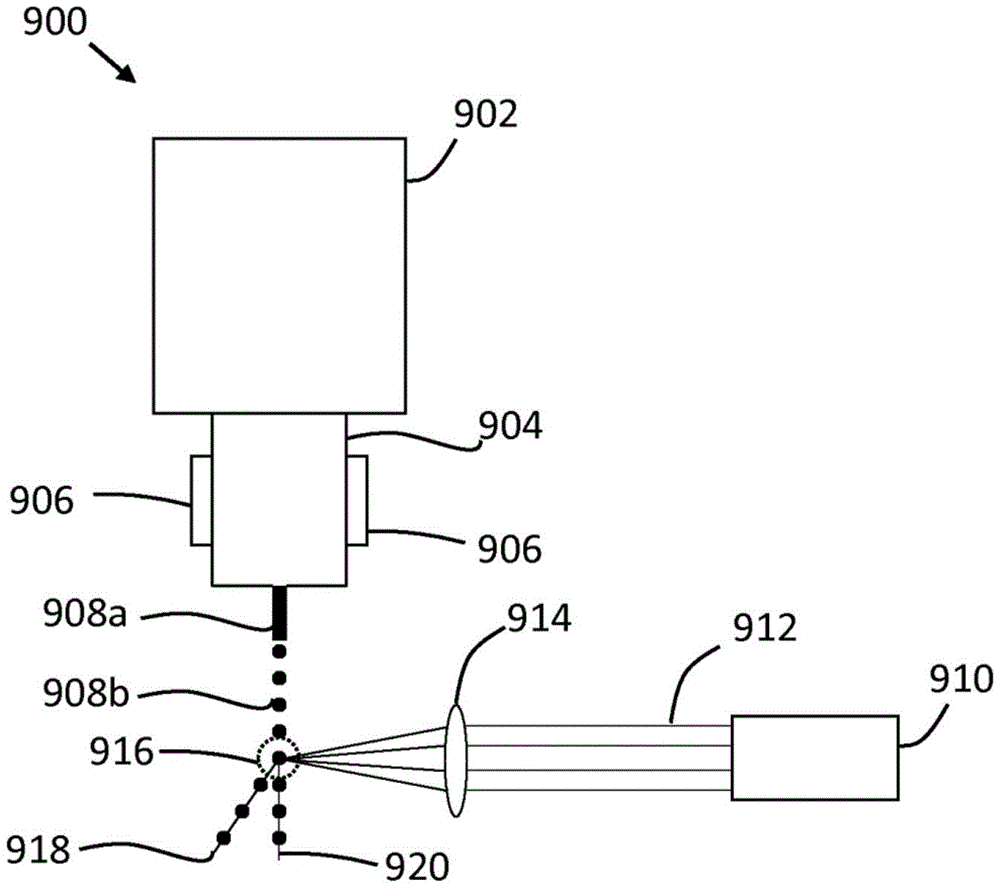
A specific example of a system 900 for displacing material is shown in fig. 9. The system 900 includes a material source 902 for containing a material, which in this example is in liquid form. Material is fed from a material source 902 through a transport module 904. The piezoelectric device 906 applies vibrations to the delivery module 904 at a defined frequency. As the material 908 exits the delivery module 904 in the form of a jet 908a, vibration from the piezoelectric device 906 causes the material to break up or break up into discrete or defined volumetric flows of material, or streams of fragmented material 908 b. The exemplary system 900 also includes a laser source 910, the laser source 910 generating a pulsed laser beam 912. An optical assembly, such as a lens 914, focuses and directs the laser beam to a point or spot such that the laser beam 912 has a defined spot size when the laser beam contacts the fragmented material in the stream of fragmented material 908 b. The laser beam 912 contacts the shredded materials in the shredded materials stream 908b at a location marked 916. Any fragmented material hit by the pulse of the laser beam 912 is caused to be displaced from the stream 908b to follow the trajectory indicated by line 918. Those fragmented materials not hit by the laser beam 912 are not displaced from the stream 908b and therefore continue along the trajectory indicated by the line 920.
As described above, the efficiency of the system 800 or 900 may be improved by using a laser beam from a single laser source, such as laser source 804 or 910, to contact and interact with the fragmented material from multiple streams of fragmented material. In this way, the cost of multiple laser sources can be saved.
To use a laser beam from a single pulsed laser source (such as a pulsed ytterbium fiber laser source) to interact with material from multiple material streams, additional components may be applied. For example, multiple material streams may be provided from multiple nozzles of a printhead of a printing apparatus. Thus, in one example, the printhead may comprise an array of N nozzles, and it may be desirable that the substance from each nozzle will be displaced by a defined distance or in a defined direction. A beam splitter may be used to split a laser beam from a laser source into a plurality of beams. In some examples, the beam splitter may split the laser beam into as many beams as there are material flows. Thus, in the printhead example described above, the beam splitter may split the laser beam into N beams; one for each nozzle in the array of nozzles. The system may further comprise a modulator, or a plurality of modulators arranged in an array, to control the power of the light beams separated by the beam splitter. In some examples, the system may include one modulator for each separate beam. Thus, in the printhead example described above, the system may include N modulators. Various modulators may be used depending on the application of the system. For example, the modulator may include an acousto-optic modulator, a micro-mechanical modulator, an electro-absorption modulator, an optical fiber modulator, and/or a liquid crystal modulator. The system may further comprise an optical fiber to receive the split light beam. In some examples, the system may include one fiber for each separate beam (i.e., N fibers in the print head example above). To efficiently receive multiple laser beams, the optical fibers may be arranged in an array, such as a V-groove array. In some examples, the system may further include a spherical lens to focus the laser beam onto the fragmented material.
In such an example system using a single laser source to displace matter from multiple streams, synchronization between laser pulses and the generation of fragmented material in multiple material streams may result in a high degree of efficiency. This synchronization may be achieved by using equipment such as piezoelectric devices to break up multiple material streams into fragmented/discrete volumes simultaneously and in a synchronized manner. In this way, multiple pieces of material, each from a different material flow, may be created simultaneously. Thus, the separate laser beams may be synchronized with the plurality of fragmented materials to simultaneously displace the plurality of fragmented materials.
Fig. 10 is a simplified schematic diagram of an example of a system 1000 for displacing material. The system 1000 may be used to displace material from multiple material streams using a single laser source. The system 1000 may include components from the system 800 described above. Specifically, the system 1000 includes a material source 802 and a laser source 804. The system 1000 also includes a beam splitter 1002 to split the pulsed laser beam into a plurality of pulsed laser beams. Each of the plurality of pulsed laser beams is aimed to strike a piece of shredded material in a corresponding one of a plurality of streams of shredded material.
The system 1000 may further include an optical modulator 1004 to control a parameter of the pulsed laser beam of the plurality of pulsed laser beams. In some examples, the parameter to be controlled may include the power or energy of the laser beam.
Examples in this disclosure may be provided as a method, system, or apparatus.
The present disclosure is described with reference to flowchart illustrations and/or block diagrams of methods, apparatus, and systems according to examples of the present disclosure. Although the flow diagrams depicted above show a particular order of execution, the order of execution may differ from that depicted. Blocks described in association with one flowchart may be combined with those in another flowchart.
Although the methods, apparatus and related aspects have been described with reference to specific examples, various modifications, alterations, omissions, and substitutions can be made without departing from the spirit of the disclosure. It is therefore intended that the methods, apparatus and related aspects be limited only by the scope of the following claims and equivalents thereof. It should be noted that the above-mentioned examples illustrate rather than limit the disclosure described herein, and that those skilled in the art will be able to design many alternative embodiments without departing from the scope of the appended claims. Features described in connection with one example may be combined with features of another example.
The word "comprising" does not exclude the presence of elements other than those listed in a claim, "a" or "an" does not exclude a plurality, and a single processor or other unit may fulfill the functions of several units recited in the claims.
Features of any dependent claim may be combined with features of any independent or other dependent claim.
Claims (15)
Applications Claiming Priority (1)
| Application Number | Priority Date | Filing Date | Title |
|---|---|---|---|
| PCT/EP2017/065496 WO2018233842A1 (en) | 2017-06-23 | 2017-06-23 | METHOD, APPARATUS AND SYSTEM FOR MOVING MATERIAL WITH A PULSED LASER BEAM |
Publications (2)
| Publication Number | Publication Date |
|---|---|
| CN110709249A CN110709249A (en) | 2020-01-17 |
| CN110709249B true CN110709249B (en) | 2021-08-06 |
Family
ID=59152902
Family Applications (1)
| Application Number | Title | Priority Date | Filing Date |
|---|---|---|---|
| CN201780091094.XA Active CN110709249B (en) | 2017-06-23 | 2017-06-23 | Method, Apparatus and System for Material Displacement Using Pulsed Laser Beams |
Country Status (4)
| Country | Link |
|---|---|
| US (2) | US11104127B2 (en) |
| EP (2) | EP3875274B1 (en) |
| CN (1) | CN110709249B (en) |
| WO (1) | WO2018233842A1 (en) |
Families Citing this family (1)
| Publication number | Priority date | Publication date | Assignee | Title |
|---|---|---|---|---|
| CN112452251B (en) * | 2020-10-27 | 2021-12-14 | 山东大学 | Crescent-shaped and deformed ceramic microparticle, preparation method, application and preparation device thereof |
Family Cites Families (13)
| Publication number | Priority date | Publication date | Assignee | Title |
|---|---|---|---|---|
| JPH02143863A (en) | 1988-11-24 | 1990-06-01 | Nec Home Electron Ltd | Ink-jet printer |
| US7108894B2 (en) * | 1998-09-30 | 2006-09-19 | Optomec Design Company | Direct Write™ System |
| EP1292398B1 (en) | 2000-06-19 | 2006-08-09 | Entegris, Inc. | Process and system for determining acceptability of a fluid dispense |
| DE10157032A1 (en) | 2001-11-21 | 2003-06-12 | Evotec Ag | Sorting particles, especially cells, comprises adjusting the waveband of an electromagnetic beam for selective acceleration into an interceptor |
| US7399401B2 (en) | 2002-10-09 | 2008-07-15 | Abbott Diabetes Care, Inc. | Methods for use in assessing a flow condition of a fluid |
| US6746108B1 (en) * | 2002-11-18 | 2004-06-08 | Eastman Kodak Company | Method and apparatus for printing ink droplets that strike print media substantially perpendicularly |
| DE102007018402A1 (en) * | 2007-04-17 | 2008-10-23 | Panasonic Electric Works Europe Ag | Method for introducing a structure into a surface of a transparent workpiece |
| US9364831B2 (en) * | 2009-08-08 | 2016-06-14 | The Regents Of The University Of California | Pulsed laser triggered high speed microfluidic switch and applications in fluorescent activated cell sorting |
| JP6214896B2 (en) | 2013-03-29 | 2017-10-18 | 株式会社日立産機システム | Inkjet recording system |
| US10157032B2 (en) | 2014-12-04 | 2018-12-18 | Henge Docks Llc | Method for logically positioning multiple display screens |
| US9694423B2 (en) | 2015-04-09 | 2017-07-04 | Siemens Energy, Inc. | Laser additive manufacturing using filler material suspended in a liquid carrier |
| CN104971788B (en) | 2015-07-21 | 2016-07-27 | 武汉大学 | A kind of optofluidic chip utilizing percussion flow and optical scattering power and for sorting the purposes of micro-nano particle |
| CN105618166B (en) | 2015-12-18 | 2017-05-10 | 武汉大学 | A Device for Sorting Metal Nanoparticles Using Fano Interferometric Light Scattering Force |
-
2017
- 2017-06-23 CN CN201780091094.XA patent/CN110709249B/en active Active
- 2017-06-23 US US16/617,167 patent/US11104127B2/en active Active
- 2017-06-23 WO PCT/EP2017/065496 patent/WO2018233842A1/en not_active Ceased
- 2017-06-23 EP EP21166194.7A patent/EP3875274B1/en active Active
- 2017-06-23 EP EP17732429.0A patent/EP3642041B1/en active Active
-
2021
- 2021-07-15 US US17/376,860 patent/US11712752B2/en active Active
Also Published As
| Publication number | Publication date |
|---|---|
| US20200122460A1 (en) | 2020-04-23 |
| US11104127B2 (en) | 2021-08-31 |
| CN110709249A (en) | 2020-01-17 |
| WO2018233842A1 (en) | 2018-12-27 |
| US11712752B2 (en) | 2023-08-01 |
| EP3642041A1 (en) | 2020-04-29 |
| US20210339527A1 (en) | 2021-11-04 |
| EP3875274A1 (en) | 2021-09-08 |
| EP3875274B1 (en) | 2023-11-15 |
| EP3642041B1 (en) | 2021-05-12 |
Similar Documents
| Publication | Publication Date | Title |
|---|---|---|
| CN110337361B (en) | Printhead cleaning system | |
| JP4189964B2 (en) | Sound ejection of fluid using a large F-number focusing element | |
| US10124602B2 (en) | Apparatuses and methods for stable aerosol deposition using an aerodynamic lens system | |
| Dadvand et al. | A collapsing bubble-induced microinjector: an experimental study | |
| JP2018523751A (en) | LIFT emission angle control | |
| JPH0957963A (en) | Method and apparatus for jetting droplet | |
| JPH01108056A (en) | Nozzle for ink jet printer | |
| KR20140112498A (en) | Methods and Systems for Use in Laser Machining | |
| KR20180022671A (en) | Laminated type manufacturing apparatus and method | |
| JP2015214036A (en) | Ink jet recorder | |
| CN111684099A (en) | Laser Induced Forward Transfer (LIFT) Deposition Apparatus and Method | |
| JP2017119358A (en) | Liquid discharge device and liquid discharge method | |
| CN106945278A (en) | Liquid ejection apparatus and liquid ejection method | |
| CN110709249B (en) | Method, Apparatus and System for Material Displacement Using Pulsed Laser Beams | |
| JP2009541093A (en) | Continuous inkjet printing using satellite drop | |
| CN111655458B (en) | Additive manufacturing with nozzles at different sheet widths | |
| TW201618601A (en) | System and method for reducing oscillation of extreme ultraviolet light generation | |
| KR20170096242A (en) | Laser processing apparatus and laser processing method | |
| JP2017119357A (en) | Liquid discharge device and method | |
| CN1616178B (en) | Laser micromachining and methods of same | |
| EP2210659A1 (en) | Effective droplet drying | |
| CN109195804B (en) | Thermal inkjet printhead and method of manufacturing the same | |
| US8079676B2 (en) | System and method for acoustic ejection of drops from a thin layer of fluid | |
| KR100708563B1 (en) | Inkjet Printing Device and Method of Manufacturing Printed Circuit Board Using the Same | |
| Rosales-Cortes et al. | Development of an optical microactuator based on thermocavitation for the drop-on-demand deposition of viscous fluids |
Legal Events
| Date | Code | Title | Description |
|---|---|---|---|
| PB01 | Publication | ||
| PB01 | Publication | ||
| SE01 | Entry into force of request for substantive examination | ||
| SE01 | Entry into force of request for substantive examination | ||
| GR01 | Patent grant | ||
| GR01 | Patent grant |